8G532001 nw adres.pmd - Solv Group
8G532001 nw adres.pmd - Solv Group
8G532001 nw adres.pmd - Solv Group

Create successful ePaper yourself
Turn your PDF publications into a flip-book with our unique Google optimized e-Paper software.
8G.53.20.01/02.07<br />
HELP REFERENCE S-HR
S-HR 15 S-HR 24/24T S-HR 35/35T S-HR 51/51T S-HR 60<br />
Table of contents<br />
page<br />
1 Foreword ........................................................................................................................................ 4<br />
2 Description of the boiler.................................................................................................................. 4<br />
3 Control the boiler ............................................................................................................................ 4<br />
3.1 Boiler pump ......................................................................................................................... 5<br />
3.2 Expansion tank .................................................................................................................... 5<br />
3.3 Room thermostat ................................................................................................................. 5<br />
3.4 Diagram of the various parts of the boiler .............................................................................. 6<br />
4 Technical specifications (up to May 1998) ...................................................................................... 8<br />
4.1 Technical specifications (from May 1998) ....................................................................................... 9<br />
5 Specific components ...................................................................................................................... 10<br />
5.1 The heat exchanger group .................................................................................................... 10<br />
5.2 The burner ............................................................................................................................ 10<br />
5.3 The fan ................................................................................................................................. 11<br />
5.4 The gas valve ....................................................................................................................... 11<br />
5.5 The temperature sensors ..................................................................................................... 12<br />
5.6 The ignition electrode ........................................................................................................... 13<br />
5.7 The water pressure sensor ................................................................................................... 13<br />
5.8 The automatic de-aeration program ...................................................................................... 13<br />
5.9 The water filter ..................................................................................................................... 14<br />
5.10 The boiler pump ................................................................................................................... 14<br />
5.11 The three-port valve .............................................................................................................. 15<br />
5.12 The condense collection device ............................................................................................ 15<br />
5.13 The control unit .................................................................................................................... 16<br />
5.14 The display .......................................................................................................................... 18<br />
6 Settings and information................................................................................................................. 19<br />
6.1 Standby Mode ..................................................................................................................... 19<br />
6.2 Parameter Mode .................................................................................................................. 20<br />
6.3 Info Mode (following code 123) ............................................................................................. 21<br />
6.4 Service Mode (following code 123) ....................................................................................... 22<br />
6.5 Error Mode (following code 123) ........................................................................................... 22<br />
6.6 Green key function ............................................................................................................... 23<br />
6.7 The Brain interface ............................................................................................................... 23<br />
7 Starting the boiler and operating the central heating ....................................................................... 24<br />
7.1 Starting the boiler and functioning of the DHW supply .......................................................... 25<br />
8 Checks and commissioning ........................................................................................................... 26<br />
8.1 Checking for contamination .................................................................................................. 26<br />
8.2 Checking the zero pressure controller .................................................................................. 26<br />
8.3 Checking the CO 2<br />
................................................................................................................ 27<br />
8.4 Maintenance ........................................................................................................................ 27<br />
8.5 Further checks..................................................................................................................... 28<br />
8.6 Frequency of maintenance ................................................................................................... 28<br />
Help reference S-HR page 2
9 Blocks ........................................................................................................................................... 29<br />
9.1 Block ....................................................................................................................... 29<br />
9.2 Block ....................................................................................................................... 30<br />
9.3 Block ....................................................................................................................... 30<br />
9.4 Block ....................................................................................................................... 31<br />
9.5 Block ....................................................................................................................... 31<br />
9.6 Block ....................................................................................................................... 32<br />
9.7 Block ....................................................................................................................... 32<br />
9.8 Block ....................................................................................................................... 33<br />
9.9 Block ....................................................................................................................... 33<br />
10 System lock boiler Errors.............................................................................................................. 34<br />
10.1 Error ........................................................................................................................ 34<br />
10.2 Error ........................................................................................................................ 35<br />
10.3 Error ........................................................................................................................ 36<br />
10.4 Error ........................................................................................................................ 37<br />
10.5 Error ........................................................................................................................ 37<br />
10.6 Error ........................................................................................................................ 38<br />
10.7 Error ........................................................................................................................ 39<br />
10.8 Error ........................................................................................................................ 39<br />
10.9 Error ........................................................................................................................ 40<br />
10.10 Error ........................................................................................................................ 41<br />
10.11 Error ........................................................................................................................ 42<br />
10.12 Error ........................................................................................................................ 43<br />
10.13 Error ........................................................................................................................ 44<br />
10.14 Error ........................................................................................................................ 45<br />
10.15 Error ........................................................................................................................ 46<br />
10.16 Error ........................................................................................................................ 47<br />
10.17 Error ........................................................................................................................ 48<br />
10.18 Error ........................................................................................................................ 49<br />
10.19 Error ........................................................................................................................ 49<br />
10.20 Error ........................................................................................................................ 50<br />
10.21 Error ........................................................................................................................ 51<br />
11 Other errors.................................................................................................................................... 52<br />
11.1 Central heating but no hot water ........................................................................................... 52<br />
11.2 Hot water but no central heating ........................................................................................... 53<br />
11.3 Central heating installation gets hot without being requested ............................................... 54<br />
11.4 Insufficient quantity of hot water ........................................................................................... 55<br />
11.5 Temperature drop of the Combi hot water ............................................................................. 56<br />
11.5.1 Temperature drop of the Solo hot water with the Comfort cylinder......................................... 57<br />
11.6 Radiators do not get hot enough or warming them up takes too long .................................... 58<br />
12 Components of the Blauwe Engel II S-HR boiler and Comfort cylinder ............................................ 59<br />
Help reference S-HR page 3
1 Foreword<br />
This help reference has been put together to make<br />
detecting and rectifying errors easier. In composing this<br />
document every effort has been made to present as much<br />
information as possible and to simulate comparable<br />
situations to attain positive results. Of course, it is<br />
impossible to describe let alone simulate all situations<br />
so that it may be possible that situations occur, which are<br />
not described or are not described in full in this help<br />
reference. It is important for ATAG that it contains this<br />
important information to be able to inform your fellow<br />
fitters in full.<br />
2 Description of the boiler<br />
The ATAG Blauwe Engel is a sealed, condensing and<br />
modulating central heating boiler supplied or not supplied<br />
with integrated hot water supply.<br />
The built-in fan sucks in the combustion air from outside<br />
and is responsible for complete pre-mixing of gas and air.<br />
The gas mix is fed through the ceramic burner, which is<br />
positioned above the heat exchanger. Thanks to the low<br />
flame height, a compact construction is possible. After<br />
the combustion gases have passed the stainless steel<br />
heat exchanger, they are vented outside. The condensation,<br />
which has formed, is drained through the assembled<br />
siphon.<br />
The boiler is approved in accordance with the valid CE<br />
standards and has the CE certificate.<br />
The operating efficiency of the boiler is higher than<br />
98 % at its upper value and 109 % at its lower value. The<br />
radiation, convection and standby losses are very low due<br />
to its compact design.<br />
The emission of harmful substances lies far below the<br />
standard, which is set for boilers with the Gaskeur<br />
Schone Verbranding (Gas Approved Clean Combustion).<br />
The boiler is fitted with an automatic venting program.<br />
This program ensures that for an installation which has<br />
just been filled (up) any available air is removed from the<br />
boiler. In this way, the controller will check the water<br />
pressure and if it is too low will indicate this on the display.<br />
The boiler anticipates the heat requirement of the central<br />
heating installation or the hot water supply. This means<br />
that the boiler will gear its output to the installation and will<br />
start up less often, which means that the boiler will be in<br />
operation for longer and at a low level. It is possible that<br />
the boiler will only need to switch itself on once an hour.<br />
In so doing it seeks to attain maximum attainable comfort<br />
and efficiency.<br />
To be able to anticipate installation sounds, the boiler has<br />
a so-called gradient controller. This controller ensures that<br />
after coming into operation the boiler does not immediately<br />
start burning at full power, but stimulates a gradual<br />
increase in power. If the installation does require full power,<br />
this controller will be regulated to realise this. As a result<br />
a gradual increase in the water temperature is achieved.<br />
If an outside sensor is connected, weather-dependent<br />
control is possible. This means that the controller<br />
measures the outside temperature and the flow water<br />
temperature in the installation.<br />
An boiler with integrated hot water supply is equipped on<br />
the right hand side with a boiler with a thermostatically<br />
controlled hot water temperature which makes sure that<br />
there is a constant hot water temperature of 60°C (factory<br />
setting).<br />
3 Control the boiler<br />
The boiler is fitted with a self-regulating controller called<br />
the Control Tower. This controller takes over a large<br />
proportion of the manual settings, which means that<br />
putting it into operation is greatly simplified.<br />
The relevant status is indicated on the display. It is<br />
possible to read out the status in two ways.<br />
The first method is a simple reading called the Good<br />
status. The boiler will only indicate the indication.<br />
The boiler can usually be in operation during this read-out<br />
without this being visible in any other way. If a message<br />
is necessary, this will be indicated on the display.<br />
The second method is a more technical method which<br />
indicates a more comprehensive read-out, with, amongst<br />
other things, the state in which the boiler is active with the<br />
flow water temperature and the water pressure of the<br />
central heating installation.<br />
The second level is attained from the indication<br />
after the Step key has been pressed for 5 seconds. Return<br />
to the indication takes place in the same way.<br />
For a heat requirement, which arises for the central heating<br />
or hot water, a particular flow water temperature will be<br />
calculated. This calculated water temperature is called the<br />
T-set value. This value becomes active for a room<br />
thermostat making the request, to which the boiler output<br />
will be controlled. For an boiler, which has just been<br />
switched on, the gradient controller of the T-set value is<br />
active. The main objective of this is to prevent the boiler<br />
from coming into operation at full power, which can result<br />
in obtrusive noises and unnecessary temperature peaks<br />
from occurring. For the heat requirement at the hot water<br />
supply, the T-set value is controlled to the central heating<br />
return water temperature. The gradient controller is no<br />
longer active. Depending upon the quantity of sanitary<br />
water, which is taken from the boiler, the central heating<br />
return water temperature will vary according to which the<br />
load on the boiler is controlled.<br />
Help reference S-HR page 4
3.1 Boiler pump<br />
The boiler has a self-regulating and fail-safe control<br />
system for the load and the pump capacity. The<br />
temperature difference between the flow and return water<br />
is thus checked. The boiler pump will be able to supply<br />
the stipulated water displacement at an installation<br />
resistance of up to 20 kPa. If the installation resistance<br />
is higher than the indicated value, the pump will start to<br />
operate at maximum pump capacity and the load will be<br />
adapted until an acceptable temperature difference between<br />
the flow and return water for the controller is<br />
reached. If subsequently the temperature difference<br />
continues to be great, the boiler will switch itself off and<br />
wait until the excessively large temperature difference<br />
between the flow and return temperature has reduced<br />
again.<br />
If an unacceptable temperature difference has been<br />
detected, the controller will repeatedly try to switch on the<br />
water flow. If this is not successful, the boiler will lock up.<br />
The S-HR 60 boiler has a boiler pump, which has a<br />
residual working head for the installation of 12 kPa. This<br />
means that the boiler is normally able to function for<br />
installations which have an installation resistance of up to<br />
12 kPa and for cascade installations.<br />
If the installation resistance is higher than 12 kPa, the<br />
boiler will automatically reduce in power.<br />
If the capacity of the boiler pump is insufficient, an extra<br />
external pump can be installed in series with the boiler.<br />
This external boiler pump can have an electrical<br />
connection to the Control Tower, which means that this<br />
pump will switch at the same times as the boiler pump.<br />
The recorded load of the external boiler pump may be up<br />
to a maximum of 1 Amp (230 V). It is also possible to<br />
select an application with an open distributor. For this,<br />
you should take into consideration the greater secondary<br />
water delivery so that the level of the water temperature<br />
is affected. The boiler is fitted as standard with a water<br />
filter in the return pipe of the boiler.<br />
This prevents any contaminated central heating water<br />
from getting into the boiler. The boiler is also fitted with<br />
an 3 bar internal overflow valve. This is jointly connected<br />
with the condensation drainage to the outlet structure into<br />
the drainage system.<br />
3.2 Expansion tank<br />
All ATAG Blauwe Engel S-HR-T Combi boilers are fitted<br />
with an expansion connection. This connection pipe is<br />
connected between the three-port valve and the boiler<br />
pump. This prevents the expansion water, when operating<br />
from the hot water supply, from being shut off from<br />
the expansion tank, if the thermostatic valves on the<br />
radiators are fully closed. A second expansion tank in the<br />
installation does not represent a problem.<br />
Not all of the ATAG Blauwe Engel S-HR Solo boilers are<br />
fitted with their own expansion tank connection. The<br />
expansion tank should therefore be connected into the<br />
return pipe directly below the boiler.<br />
The ATAG Blauwe Engel S-HR Solo boilers, which are<br />
put in combination with an ATAG Comfort cylinder have<br />
an expansion tank connection incorporated into the<br />
pipework for the ATAG Comfort cylinder, to which the<br />
expansion tank must be connected. If another boiler is<br />
used one should take into account that the expansion<br />
tank is connected between the three-port valve and the<br />
boiler boiler pump.<br />
To ensure that the boiler functions correctly,<br />
it is essential that the expansion tank always<br />
is within range of the expanding central<br />
heating water.<br />
3.3 Room thermostat<br />
The ATAG Brain thermostat and controls should be<br />
connected to the intended connections. All other types or<br />
makes of room thermostats or controls, which are used,<br />
should have a potential-free contact.<br />
When using an on / off thermostat or controller it is possible<br />
that a pre-emptive resistor should be positioned to<br />
prevent excessive swings in temperature. Generally,<br />
mercury thermostats are intended here. This resistance<br />
wire is present in the Control Tower cabinet and should be<br />
fitted to terminals 23 and 27. The pre-emptive resistor in<br />
the room thermostat should be set to 0.11 A.<br />
If all or a large proportion of the radiators are fitted with<br />
thermostatic radiator valves, a pressure difference controller<br />
should be used to prevent flow problems in the<br />
installation.<br />
Help reference S-HR page 5
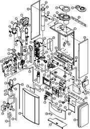
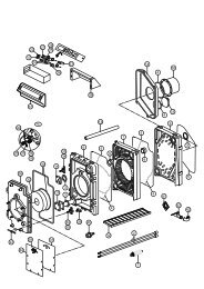
3.4 Diagram of the various parts of the boiler<br />
3 T5<br />
18<br />
5<br />
4<br />
8<br />
7<br />
9<br />
T1<br />
T2<br />
2<br />
1<br />
6<br />
P1<br />
T3<br />
14<br />
10<br />
11<br />
15<br />
17<br />
12 13<br />
16<br />
G A R C E K W<br />
boiler diagram figure 1<br />
G<br />
A<br />
R<br />
C<br />
E<br />
K<br />
W<br />
T1<br />
T2<br />
T3<br />
T5<br />
P1<br />
gas line<br />
flow line CH<br />
return line CH<br />
condense line<br />
expansion vassle line<br />
cold water line<br />
hot water line<br />
flow sensor<br />
return sensor<br />
cylinder sensor<br />
flue gas sensor<br />
water pressure sensor<br />
Help reference S-HR page 6
oiler description figure 2<br />
1 heat exchanger<br />
2 ignition electrode<br />
3 fan<br />
4 silencer<br />
5 gas valve<br />
6 safety valve<br />
7 automatic fan<br />
8 ceramic burner<br />
9 DHW cylinder (S-HR-T)<br />
10 control panel<br />
11 Control Tower<br />
12 water filter return CH<br />
13 three-port valve<br />
14 boilerpump<br />
15 safety valve (S-HR-T)<br />
16 dosing valve (S-HR-T)<br />
17 thermostatic mixing valve (S-HR-T)<br />
18 flue gas discharge<br />
19 combustion air supply<br />
20 air box<br />
21 type plate<br />
Help reference S-HR page 7
4 Technical specifications (up to May 1998)<br />
appliance type<br />
S-HR<br />
15<br />
S-HR<br />
24<br />
S-HR<br />
24T<br />
S-HR<br />
35<br />
S-HR<br />
35T<br />
S-HR<br />
51<br />
S-HR<br />
51T<br />
S-HR<br />
60<br />
load<br />
on upper value<br />
load<br />
on lower value<br />
modulation<br />
modulation<br />
range (capacity 80/60°C)<br />
range (capacity 50/30°C)<br />
kW<br />
15,<br />
0 24,<br />
0 24,<br />
0 35,<br />
0 35,<br />
0 51,<br />
0 51,<br />
0 60, 0<br />
kW<br />
13,<br />
5 21,<br />
6 21,<br />
6 31,<br />
5 31,<br />
5 45,<br />
9 45,<br />
9 54, 0<br />
kW<br />
6,4-13,<br />
3 6,4-21,<br />
2 6,4-21,<br />
2 4,9-30,<br />
9 4,9-30,<br />
9 8,8-45,<br />
0 8,8-45,<br />
0 8,8-52, 9<br />
kW<br />
7-14,<br />
4 7-23,<br />
0 7-23,<br />
0 5,3-33,<br />
6 5,3-33,<br />
6 9,5-48,<br />
7 9,5-48,<br />
7 9,5-57, 2<br />
e fficiency (80/60°C at full load)<br />
% 98<br />
98<br />
98<br />
98<br />
98<br />
98<br />
98<br />
98<br />
e fficiency (50/30°C at full load)<br />
% 107<br />
107<br />
107<br />
107<br />
107<br />
106<br />
106<br />
106<br />
e fficiency in accordance with EN677<br />
% 109<br />
109<br />
109<br />
109<br />
109<br />
109<br />
109<br />
109<br />
Yearly<br />
emission of NOx<br />
Yearly<br />
emission of CO<br />
ppm<br />
12<br />
12<br />
12<br />
12<br />
12<br />
12<br />
12<br />
12<br />
ppm<br />
11<br />
11<br />
11<br />
11<br />
11<br />
11<br />
11<br />
11<br />
CO<br />
2<br />
% 9 9 9 9 9 9,<br />
5 9,<br />
5 9, 5<br />
flue<br />
gas temperature (at 80/60°Cat full load)<br />
flue<br />
gas temperature (at 50/30°C at low load)<br />
burner<br />
control<br />
gas<br />
consumption (at 1013 mbar/0°C) G20<br />
burner<br />
type<br />
current<br />
type<br />
° C 65<br />
65<br />
65<br />
67<br />
67<br />
68<br />
68<br />
68<br />
° C 31<br />
31<br />
31<br />
31<br />
31<br />
31<br />
31<br />
31<br />
stepless modulatio n<br />
m³/<br />
h 1,32<br />
2,10<br />
2,10<br />
3,07<br />
3,07<br />
4,47<br />
4,47<br />
5,26<br />
ceramic<br />
V/Hz<br />
230/50<br />
230/50<br />
230/50<br />
230/50<br />
230/50<br />
230/50<br />
230/50<br />
230/50<br />
maximum electric power recorded<br />
W 122<br />
122<br />
122<br />
145<br />
145<br />
190<br />
190<br />
190<br />
standby<br />
electric power recorded<br />
W 5 5 5 5 5 5 5 5<br />
degree<br />
of protection according to EN60529<br />
IP 40<br />
IP 40<br />
IP 40<br />
IP 40<br />
IP 40<br />
IP 40<br />
IP 40<br />
IP 40<br />
weight<br />
(net)<br />
kg<br />
50<br />
50<br />
73<br />
53<br />
76<br />
63<br />
86<br />
63<br />
water<br />
capacity CH-based<br />
l 3,<br />
5 3,<br />
5 3,<br />
5 5 5 7 7 7<br />
water<br />
capacity DHW-based<br />
l 14<br />
14<br />
13<br />
pump<br />
pump<br />
minimum<br />
maximum<br />
overrun time CH<br />
overrun time DHW<br />
water<br />
pressure<br />
water<br />
pressure<br />
maximum flow water temperature<br />
tap<br />
flow rate at 60°C<br />
tap<br />
flow rate at 45°C<br />
pump<br />
type<br />
available<br />
pump head<br />
min<br />
15<br />
15<br />
15<br />
15<br />
15<br />
15<br />
15<br />
15<br />
min<br />
1 1 1<br />
bar<br />
1 1 1 1 1 1 1 1<br />
bar<br />
3 3 3 3 3 3 3 3<br />
° C 90<br />
90<br />
90<br />
90<br />
90<br />
90<br />
90<br />
90<br />
l/mi<br />
n<br />
6 8,<br />
5<br />
12, 5<br />
l/mi<br />
n<br />
8,<br />
5<br />
12,<br />
5<br />
17, 5<br />
Wilo<br />
ARS<br />
25/70<br />
ARS<br />
25/70<br />
ARS<br />
25/70<br />
ARS<br />
25/70<br />
ARS<br />
25/70<br />
ARS<br />
25/75<br />
ARS<br />
25/75<br />
ARS<br />
25/75<br />
kPa<br />
35<br />
25<br />
25<br />
20<br />
20<br />
20<br />
20<br />
12<br />
expansion<br />
vessel content<br />
l 12<br />
12<br />
expansion<br />
vessel pre-pressure<br />
bar<br />
1 1<br />
boiler specifications table 1<br />
Help reference S-HR page 8
4.1 Technical specifications (from May 1998)<br />
appliance type<br />
S-HR<br />
15<br />
S-HR<br />
24<br />
S-HR<br />
24T<br />
S-HR<br />
35<br />
S-HR<br />
35T<br />
S-HR<br />
51<br />
S-HR<br />
51T<br />
S-HR<br />
60<br />
load<br />
on upper value<br />
load<br />
on lower value<br />
modulation<br />
modulation<br />
range (capacity 80/60°C)<br />
range (capacity 50/30°C)<br />
kW<br />
15,<br />
0 24,<br />
0 24,<br />
0 35,<br />
0 35,<br />
0 51,<br />
0 51,<br />
0 60, 0<br />
kW<br />
13,<br />
5 21,<br />
6 21,<br />
6 31,<br />
5 31,<br />
5 45,<br />
9 45,<br />
9 54, 0<br />
kW<br />
3,5-13,<br />
3 3,5-21,<br />
2 3,5-21,<br />
2 4,9-30,<br />
9 4,9-30,<br />
9 8,8-45,<br />
0 8,8-45,<br />
0 8,8-52, 9<br />
kW<br />
3,9-14,<br />
4 3,9-23,<br />
0 3,9-23,<br />
0 5,3-33,<br />
6 5,3-33,<br />
6 9,5-48,<br />
7 9,5-48,<br />
7 9,5-57, 2<br />
e fficiency (80/60°C at full load)<br />
% 98<br />
98<br />
98<br />
98<br />
98<br />
98<br />
98<br />
98<br />
e fficiency (50/30°C at full load)<br />
% 107<br />
107<br />
107<br />
107<br />
107<br />
106<br />
106<br />
106<br />
e fficiency in accordance with EN677<br />
% 109<br />
109<br />
109<br />
109<br />
109<br />
109<br />
109<br />
109<br />
Yearly<br />
emission of NOx<br />
Yearly<br />
emission of CO<br />
ppm<br />
12<br />
12<br />
12<br />
12<br />
12<br />
12<br />
12<br />
12<br />
ppm<br />
11<br />
11<br />
11<br />
11<br />
11<br />
11<br />
11<br />
11<br />
CO<br />
2<br />
% 9 9 9 9 9 9,<br />
5 9,<br />
5 9, 5<br />
flue<br />
gas temperature (at 80/60°Cat full load)<br />
flue<br />
gas temperature (at 50/30°C at low load)<br />
burner<br />
control<br />
gas<br />
consumption (at 1013 mbar/0°C) G20<br />
burner<br />
type<br />
current<br />
type<br />
° C 65<br />
65<br />
65<br />
67<br />
67<br />
68<br />
68<br />
68<br />
° C 31<br />
31<br />
31<br />
31<br />
31<br />
31<br />
31<br />
31<br />
stepless modulatio n<br />
m³/<br />
h 1,32<br />
2,10<br />
2,10<br />
3,07<br />
3,07<br />
4,47<br />
4,47<br />
5,26<br />
ceramic<br />
foam ceramic<br />
V/Hz<br />
230/50<br />
230/50<br />
230/50<br />
230/50<br />
230/50<br />
230/50<br />
230/50<br />
230/50<br />
maximum electric power recorded<br />
W 122<br />
122<br />
122<br />
145<br />
145<br />
190<br />
190<br />
190<br />
standby<br />
electric power recorded<br />
W 5 5 5 5 5 5 5 5<br />
degree<br />
of protection according to EN60529<br />
IP 40<br />
IP 40<br />
IP 40<br />
IP 40<br />
IP 40<br />
IP 40<br />
IP 40<br />
IP 40<br />
weight<br />
(net)<br />
kg<br />
50<br />
50<br />
73<br />
53<br />
76<br />
63<br />
86<br />
63<br />
water<br />
capacity CH-based<br />
l 3,<br />
5 3,<br />
5 3,<br />
5 5 5 7 7 7<br />
water<br />
capacity DHW-based<br />
l 14<br />
14<br />
13<br />
pump<br />
pump<br />
minimum<br />
maximum<br />
overrun time CH<br />
overrun time DHW<br />
water<br />
pressure<br />
water<br />
pressure<br />
maximum flow water temperature<br />
tap<br />
flow rate at 60°C<br />
tap<br />
flow rate at 45°C<br />
pump<br />
type<br />
available<br />
pump head<br />
min<br />
15<br />
15<br />
15<br />
15<br />
15<br />
15<br />
15<br />
15<br />
min<br />
1 1 1<br />
bar<br />
1 1 1 1 1 1 1 1<br />
bar<br />
3 3 3 3 3 3 3 3<br />
° C 90<br />
90<br />
90<br />
90<br />
90<br />
90<br />
90<br />
90<br />
l/mi<br />
n<br />
6 8,<br />
5<br />
12, 5<br />
l/mi<br />
n<br />
8,<br />
5<br />
12,<br />
5<br />
17, 5<br />
Wilo<br />
ARS<br />
25/70<br />
ARS<br />
25/70<br />
ARS<br />
25/70<br />
ARS<br />
25/70<br />
ARS<br />
25/70<br />
ARS<br />
25/75<br />
ARS<br />
25/75<br />
ARS<br />
25/75<br />
kPa<br />
35<br />
25<br />
25<br />
20<br />
20<br />
20<br />
20<br />
12<br />
expansion<br />
vessel content<br />
l 12<br />
12<br />
expansion<br />
vessel pre-pressure<br />
bar<br />
1 1<br />
boiler specifications table 2<br />
Help reference S-HR page 9
5 Specific components<br />
The following components are specific ATAG parts or<br />
applications and can only be replaced with ATAG parts<br />
when it comes to replacing them.<br />
5.1 The heat exchanger group<br />
The stainless steel heat exchanger is made up of several<br />
components, which go to make up a complete heat<br />
exchanger group.<br />
5.2 The burner<br />
The boilers are dependant upon the power, supplied from<br />
ceramic burner. Due to the different resistances for the<br />
various types of boiler, it is important that each boiler has<br />
its own set of burner bricks, which have been chosen for<br />
the boiler. It is only therefore possible to replace these<br />
burner bricks with those of the same design.<br />
In addition, individual burner bricks have a so-called<br />
profiled side (the side with grooves running the length or<br />
width). This profile side should always be located<br />
upwards as illustrated in the diagrams.<br />
The flame side will be darkly coloured after first use. In<br />
contrast, the foam ceramic burner bricks for the S-HR 51<br />
and 60 are black on the flame side from the factory.<br />
view of heat exchanger group S-HR 35 / S-HR 35T figure 3<br />
The parts belonging to the heat exchanger group are:<br />
- heat exchanger<br />
- baffle plates<br />
- automatic de-aerator<br />
- temperature sensors<br />
- water pressure sensor<br />
- ignition and ionisation electrode<br />
top view of burner bricks S-HR 15 / S-HR 24/24T figure 4<br />
The material design of the heat exchanger is RBS 316 Ti.<br />
The pipes are flat and are subdivided into two diameters.<br />
The outside row of thinner pipes are intended for cooling<br />
the combustion space, whereas the middle pipes are<br />
responsible for the output.<br />
The internal cleaning of the pipes is not necessary and is<br />
not recommended. Neither is it recommended to remove<br />
the aluminium baffle plates from the exchanger.<br />
The pipes can be externally cleaned using<br />
a hard brush (not a steel brush) and water.<br />
top view of burner bricks S-HR 35 / S-HR 35T figure 5<br />
Help reference S-HR page 10
top view of burner bricks S-HR 51/51T / S-HR 60 figure 6<br />
(up to April 1998)<br />
view of van figure 8<br />
When replacing the motor the whole fan, as illustrated,<br />
should be replaced.<br />
Cleaning of the plastic fan impeller is only recommended<br />
using compressed air (max. 6 bar).<br />
5.4 The gas valve<br />
top view of burner bricks S-HR 51/51T / S-HR 60 figure 7<br />
(from April 1998)<br />
The gas valve is the same for all types of ATAG Blauwe<br />
Engel S-HR boilers. They are driven using 24 volts. This<br />
gas valve is adjusted using a so-called zero pressure<br />
adjustment. As a result of making this adjustment, it will<br />
no longer be possible to read the burner pressure.<br />
For more information see chapter 8 "Checking and<br />
commissioning".<br />
The burner bricks can best be cleaned<br />
using compressed air (max. 6 bar and<br />
blow in the opposite direction) and if<br />
applicable using a soft brush. Never use<br />
water to clean the burner stones.<br />
5.3 The fan<br />
The fan is positioned at the top of the heat exchanger.<br />
There are two designs of heat exchanger:<br />
For the types S-HR 15; S-HR 24/24T and S-HR 35/35T<br />
- only 24 volt power supply and control (identifiable by<br />
the individual plug connection)<br />
view of gasblock figure 9<br />
For the types S-HR 51/51T and S-HR 60<br />
- 24 volt control and 230 volt supply voltage (identifiable<br />
by the twin plug connection)<br />
Help reference S-HR page 11
5.5 The temperature sensors<br />
The boilers are fitted with several temperature sensors<br />
(NTC). The following sensors are present:<br />
- T1 flow sensor<br />
- T2 return sensor<br />
- T3 DHW cylinder sensor<br />
- T4 outside temperature sensor (optional)<br />
- T5 flue gas sensor (optional)<br />
The controller independently checks and corrects the<br />
temperature of the flow and return sensor. In a nonburning<br />
situation, these should correspond with one<br />
another.<br />
view of flue gas sensor T5 figure 13<br />
All temperature sensors which are connected to the<br />
boiler are NTC sensors (12 kOhm at 25°C). This means<br />
that if the temperature increases, the resistance will fall.<br />
view of flow sensor T1 figure 10<br />
view of return sensor T2 and DHW cylinder sensor T3 figure 11<br />
view of outside temperature sensor T4 figure 12<br />
Temp<br />
°C<br />
NTC<br />
12 K (12 kW / 25°C)<br />
flow sensor T1<br />
return sensor T2<br />
DHW cylinder sensor T3<br />
outside temperature sensor T4<br />
flue gas sensor T5<br />
-20<br />
98.900<br />
-18<br />
-16<br />
-14<br />
-12<br />
-10<br />
0-8<br />
0-6<br />
0-4<br />
0-2<br />
0-0<br />
002<br />
004<br />
006<br />
008<br />
010<br />
012<br />
014<br />
016<br />
018<br />
020<br />
022<br />
024<br />
025<br />
026<br />
028<br />
030<br />
032<br />
034<br />
036<br />
038<br />
040<br />
045<br />
050<br />
055<br />
060<br />
88.950<br />
80.100<br />
72.200<br />
65.150<br />
58.900<br />
53.300<br />
48.250<br />
43.750<br />
39.750<br />
36.150<br />
32.900<br />
29.950<br />
27.350<br />
24.950<br />
22.800<br />
20.850<br />
19.100<br />
17.500<br />
16.100<br />
14.750<br />
13.600<br />
12.500<br />
12.000<br />
11.500<br />
10.600<br />
09.800<br />
09.100<br />
08.350<br />
07.750<br />
07.200<br />
06.650<br />
05.525<br />
04.600<br />
03.850<br />
03.250<br />
070<br />
02.325<br />
080<br />
01.700<br />
090<br />
01.275<br />
100<br />
0.<br />
0950<br />
recistance table NTC-sensoren table 3<br />
Help reference S-HR page 12
5.6 The ignition electrode<br />
ATAG has combined the ignition electrode, ionisation<br />
electrode and the inspection glass section into one part.<br />
This electrode should only be exchanged if visible wear<br />
and tear can be observed.<br />
It should be replaced as a complete unit and it is advisable<br />
also to replace the packing. When locating the electrode<br />
with the packing remember that the packing should be<br />
fitted correctly.<br />
view of ignition electrode figure 14<br />
5.7 The water pressure sensor<br />
The water pressure sensor is an electronic sensor which<br />
indicates water pressures based upon the resistance.<br />
The water pressure sensor ensures that the boiler<br />
responds to water pressure, which is excessively low or<br />
high.<br />
The water pressure sensor also checks whether the<br />
boiler pump is working properly. This is done using the<br />
pressure difference between a pomp on standby and one<br />
which is running. Make sure therefore when fitting a<br />
second boiler pump that it is connected to connection 4,<br />
5 and 6 of the connecting block in the Control Tower. As<br />
a result, this pump will be electrically switched in parallel<br />
with the boiler pump.<br />
view of water pressure sensor figure 15<br />
The water pressure sensor responds in the event of the<br />
following water pressures:<br />
Water pressure is too low (between 0.0 and 0.3<br />
bar), text remains visible and alternates<br />
with the water pressure designation. The boiler is<br />
put out of operation. The pump comes into<br />
operation if there is any risk of frost.<br />
The installation should be filled up.<br />
Water pressure is too low (between 0.3 and 0.7<br />
bar), text remains visible and alternates<br />
with the water pressure designation. The boiler is<br />
put out of operation. The pump comes into<br />
operation if there is any risk of frost or when the<br />
pump continuous program is active.<br />
The installation should be filled up.<br />
Water pressure is too low (between 0.7 and 1.0<br />
bar), flashing text alternates with the<br />
water pressure designation, 50 % boiler power<br />
possible.<br />
The installation should be filled up.<br />
When a water pressure of 1.5 bar has been<br />
attained, for a short time the display will be<br />
shown alternating with the water pressure<br />
designation to indicate to stop filling. The deaeration<br />
program will then automatically be<br />
started if one of the three program keys is<br />
switched on.<br />
Water pressure is too high (> 3.5 bar), text<br />
remains continuously visible, the boiler is put out<br />
of operation.<br />
The installation pressure should be reduced be<br />
bleeding off water.<br />
The operating pressure of the boiler normally lies between<br />
the minimum 1.0 bar (in its cold state) and the maximum<br />
2.5 bar (in its warm state).<br />
5.8 The automatic de-aeration program<br />
The 15 minute automatic de-aeration program is<br />
independently started if the controller see that the press<br />
is getting high again after it has been filled up. When an<br />
boiler is put into operation for the first time using one of<br />
three program keys, the 15 minute automatic de-aeration<br />
program is also started. appears on the display,<br />
whereby the indicates the automatic de-aeration program<br />
and the figure indicates the flow water temperature<br />
(T1).<br />
If one of the programs had been switched off prior to a<br />
power failure, then the boiler will automatically start the<br />
15 minute de-aeration program. The de-aeration program<br />
can only be interrupted after entering the access code by<br />
briefly pressing the reset key. The de-aeration program<br />
can be started by holding the reset key down for 5<br />
seconds.<br />
Help reference S-HR page 13
5.9 The water filter<br />
All S-HR boilers have a water filter located in the return.<br />
It is not necessary to clean this water filter when<br />
servicing. The boiler will itself indicate if a water filter is<br />
contaminated due to the fact that insufficient flow will be<br />
detected via the boiler.<br />
The central heating installation should be<br />
filled with drinking water.<br />
If after some time the temperature<br />
difference between the flow and the return<br />
water is too great or there are flow<br />
problems or the installation is not hot<br />
enough, the water filter may be blocked.<br />
Put the boiler out of operation, bleed the<br />
boiler and clean the filter.<br />
It is set out in table 4 what the pump yield is at an average<br />
T of 20°C and given a capacity of the boiler pump of<br />
100%. The residual working head of the boiler pump<br />
corresponds with the permissible installation resistance.<br />
If this installation resistance is exceeded, the average T<br />
controller responds to this by setting the boiler pump to<br />
maximum rpm and if necessary to reduce the burner<br />
power. The possible consequence of this is that the<br />
installation will not come up to temperature or not<br />
sufficiently.<br />
If the installation resistance is such that the average T<br />
controller causes the boiler to switch off as a result, a<br />
Block 11 (for central heating) occurs temporarily. After<br />
some time, the controller will try again to start to create<br />
an acceptable average T . If this error occurs 3 times,<br />
a longer Block 11 occurs. If this takes place via the boiler<br />
circuit, this is called Block 12. If this Block occurs it is<br />
recommended to reduce the installation resistance using<br />
a pressure difference controller (see the installation<br />
instructions for the boiler).<br />
7<br />
H(m)<br />
view of the waterfilter figure 16<br />
5.10 The boiler pump<br />
6<br />
5<br />
4<br />
3<br />
max (100 %)<br />
pump index line ARS 25-75<br />
pump index line ARS 25-70<br />
S-HR 24T/35T<br />
S-HR 15/24/35<br />
S-HR 51T<br />
S-HR 51/60<br />
The S-HR boilers have a modulating boiler pump, which<br />
is located in the return pipe of the boiler. There are two<br />
different types of pumps to be distinguished:<br />
The ARS 25/70 type pump appears in the boilers:<br />
- S-HR 15;<br />
- S-HR 24/24T;<br />
- S-HR 35/35T.<br />
The ARS 25/75 type pump appears in the boilers:<br />
- S-HR 51/51T;<br />
- S-HR 60.<br />
2<br />
1<br />
0<br />
min (25%)<br />
0 0,5 1 1,5 2 2,5<br />
Q(m³/h)<br />
pump index line grafic 1<br />
type<br />
of unit<br />
water flow rate<br />
DT<br />
20° C<br />
l/min<br />
l/<br />
h<br />
permissible<br />
installation resistance<br />
kPa<br />
mbar<br />
S-HR<br />
15 9.<br />
9 600<br />
35<br />
350<br />
S-HR<br />
24/24T 15,<br />
1 980<br />
25<br />
250<br />
S-HR<br />
35/35T 22,<br />
1 1324<br />
20<br />
200<br />
S-HR<br />
51/51T 32,<br />
1 1929<br />
20<br />
200<br />
S-HR<br />
60 37,<br />
9 2271<br />
12<br />
120<br />
available water flow on full load table 4<br />
Help reference S-HR page 14
5.11 The three-port valve<br />
All S-HR-T Combi boilers are designed with a sliding<br />
three-port valve. The hot water always has priority and the<br />
controller will always cause the three-port valve to be set<br />
to the hot water supply, whilst hot water is being used.<br />
Depending upon the size of the boiler and the quantity of<br />
hot water, which is bled from the boiler, it is possible, if<br />
the boiler has sufficient power, for the Combi program to<br />
become active. This Combi program ensures that at the<br />
same time heat goes both to the boiler and to the central<br />
heating installation. A detection system in the controller<br />
ensures that the sanitary water in the boiler does not cool<br />
down too much thus preventing a temperature drop. In<br />
this way comfort is increased by also having warm<br />
radiators whilst showering.<br />
The Combi program can only be active if:<br />
- both the boiler and the central heating installation<br />
have a heat requirement;<br />
- the VC6940 type three-port valve is present<br />
- the power has sufficient power<br />
- the temperature difference between the requested<br />
central heating water and the water produced in the<br />
boiler is not greater than 15°C.<br />
There are two different types of three-port valves which<br />
can be distinguished:<br />
- The VC2010 design is an open / close three-port valve<br />
and appears in the S-HR 24T boiler.<br />
- The VC6940 is a modulating three-port valve and<br />
appears in the S-HR 35T and the S-HR 51T boilers.<br />
5.12 The condense collection device<br />
The condensation and overflow water are jointly drained<br />
into a drainage pipe.<br />
Overflow or condensation water is released into the<br />
drainage pipe by the following components:<br />
- the heat exchanger<br />
- the flue gas venting system<br />
- the 3 bar overflow<br />
- the automatic de-aerator<br />
- the inlet combination (S-HR-T)<br />
The drainage of condensation should be connected to the<br />
sewage system by means of an open connection. To<br />
avoid any excess build-up of stench, the connection, to<br />
which the condensation drainage is connected into the<br />
sewage system, must be fitted with a siphon. The siphon<br />
present in the boiler is not intended for this. This namely<br />
should prevent any flue gases from escaping into the<br />
room in which it is set up. The siphon beaker underneath<br />
the condense collection device is sealed by means of an<br />
O-ring assembly. It is not necessary to pack the wire<br />
connection neither is it recommended.<br />
A seal is quickly made by the O-ring, as a<br />
result of which it is neither necessary nor<br />
recommended to tighten the siphon<br />
beaker with force. If necessary, the O-ring<br />
can be greased with acid-free Vaseline<br />
when servicing.<br />
The modulating drive is supplied by the Control Tower.<br />
The drive is stepped.<br />
The three-port valves are always voltage-free in the last<br />
selected state, which means that it never has an automatic<br />
back-flow mechanism (spring). To flow back to the<br />
other position, the three-port valve receives voltage again<br />
(for electrical connections see the connection diagram for<br />
the boiler).<br />
view of the condense collection device figure 18<br />
view of the three-port valve figure 17<br />
Help reference S-HR page 15
5.13 The control unit<br />
All devices have the same ATAG control unit type 1415D.<br />
The group of control unit, display, terminal strip and any<br />
installed interface (which is responsible for communication<br />
between the control unit and the ATAG Brain) is<br />
called the Control Tower. All of these components can be<br />
individually replaced. The power supply for the control unit<br />
is provided by an externally located transformer (behind<br />
the Control Tower).<br />
The memory for the control unit is great, which means<br />
that a large number of settings can be programmed.<br />
Settings which can be boiler-, installation- and even<br />
customer-specific. These settings are stored in the<br />
memory of both the control unit and the display. When<br />
replacing one of these two components, the newly<br />
installed component will be loaded with the available<br />
memory. This procedure can be seen from the<br />
text. It may sometimes occur that the controller requests<br />
a confirmation to this procedure by indicating or<br />
. The confirmation can be given by briefly pressing<br />
the "Store" button. It is then necessary to re-enter the<br />
programmed settings, as they are already stored.<br />
Control units which are replaced, can only be replaced<br />
using ATAG specific components.<br />
view of the control unit figure 19<br />
Differences in parameter settings, which are loaded in the<br />
control unit, mean that the devices are type-specific. The<br />
power for an S-HR 15 is different to that of an S-HR 60.<br />
Which program is loaded in the boiler and which type of<br />
boiler it is, is displayed when the control unit is powered<br />
up. The display first of all indicates the type of device<br />
followed by the software version .<br />
The control unit has its own internal controller. For both<br />
the central heating and the hot water program, for<br />
example, separate temperatures and power settings can<br />
be set.<br />
What is more, the controller makes the boiler fail-safe.<br />
This is achieved thanks to the average T controller. This<br />
controller continuously checks whether there is an<br />
acceptable temperature difference between the flow and<br />
return water. If this is too great, which can be harmful for<br />
the boiler, the pump rpm is automatically increased,<br />
which results in more water being circulated. If this does<br />
not have sufficient effect, the pump will be set to its<br />
maximum rpm, after which , if necessary, the power from<br />
the boiler will be reduced. When an acceptable average<br />
T has once again been measured, the power will attempt<br />
to adopt the old modulation level. This prevents the boiler<br />
from suffering irreparable damage and unnecessary<br />
fouling.<br />
connection block in the Control Tower<br />
main power<br />
supply<br />
230 Volts for<br />
external pump<br />
230 Volts for<br />
external control<br />
230 Volts for Brain<br />
interface<br />
internal or external<br />
three-port valve<br />
motor and DHW<br />
cylinder sensor<br />
ATAG outside<br />
sensor<br />
ATAG Brain<br />
room thermostat<br />
on / off thermostat<br />
or controller<br />
external<br />
safety contact<br />
24 Volts<br />
maximum 100 mA<br />
connection diagram figure 20<br />
Help reference S-HR page 16
Help reference S-HR page 17<br />
electrical connection diagram figure 21
5.14 The display<br />
As indicated, all boilers have the same design display.<br />
The difference is in the programmed software, which<br />
differs per type of boiler. The memory for the software is<br />
present in the control unit and the display. The display<br />
has various push buttons, which have different functions.<br />
What is more, the keys can be divided into so-called user<br />
keys and service keys.<br />
User key functions<br />
The following keys have the following functions in the<br />
"Standby" mode (see chapter 6):<br />
- (central heating) program key, for switching the<br />
heating program on or off;<br />
- (hot water) program key, for switching the hot<br />
water program on or off;<br />
- (pump) program key, circulating the pump<br />
continuously through the central heating installation,<br />
or according to the overrun times of the relevant<br />
programs;<br />
- Mode key, after pressing it briefly, a chapter can be<br />
selected;<br />
- Step key, after pressing it briefly, the water pressure<br />
can be requested. After holding it pressed down for 5<br />
seconds, it switches over from indication to<br />
the technical indication and back again;<br />
- Reset key, after pressing it briefly an error is restored.<br />
Service key functions<br />
The following keys have the following functions in the<br />
other modes (see chapter 6):<br />
- (central heating) key has the + function;<br />
- (hot water) key has the - function;<br />
- (pump) key has the store function, which means<br />
that using this key a modified setting is confirmed, or<br />
an instruction can be confirmed;<br />
- Mode key, after pressing it for 5 seconds the option is<br />
given to enter the access code. In addition, it is<br />
possible to select between the different chapters;<br />
- Step key for scrolling through the chapters;<br />
- Reset key, after pressing it briefly the entered access<br />
code is completed.<br />
After pressing for 5 seconds a complete operational<br />
shutdown occurs, for example, for activating the<br />
automatic de-aeration program.<br />
Completing the automatic de-aeration program is only<br />
possible after the access code has been entered, after<br />
which the program is stopped after briefly pressing the<br />
reset key.<br />
The two chapters "Standby" and "Para" can be accessed<br />
after pressing the mode key.<br />
display<br />
CH progr.<br />
on / off<br />
HW progr.<br />
on / off<br />
pump progr.<br />
on / off<br />
Mode key<br />
Step key<br />
Reset key<br />
view of the display figure 22<br />
Operation indication (in the first display position)<br />
0 No heat requirement<br />
1 Ventilation phase<br />
2 Ignition phase<br />
3 Burner active on central heating<br />
4 Burner active on hot water<br />
5 Fan check<br />
6 Burner off when room thermostat is demanding<br />
7 Pump overrun phase for central heating<br />
8 Pump overrun phase for hot water<br />
9 Burner off because of too high flow water temperature<br />
A Automatic venting programme<br />
Help reference S-HR page 18
6 Settings and information<br />
Settings can be programmed into the Control Tower and<br />
information about the boiler and the controller can be<br />
requested. Overall operation takes place using the keys<br />
present on the boiler in combination with the display.<br />
The structure of the Control Tower can be considered to<br />
be like a book with 5 chapters. Each chapter, which is<br />
selected using the Mode key, has a number of pages and<br />
these are requested using the Step key. The 5 chapters<br />
are displayed after entering the access code and<br />
pressing the Mode key.<br />
Standby mode<br />
Chapter during normal use. The normal operating<br />
functions such as the simple read-out or the<br />
technical with the read-out are displayed.<br />
Parameter mode<br />
Chapter in which settings can be programmed.<br />
Info mode<br />
Chapter in which information can be requested.<br />
Service mode<br />
Chapter in which manual settings can be entered for<br />
servicing purposes.<br />
Error mode<br />
Chapter in which error data can be requested.<br />
ATAG has integrated a number of levels to prevent<br />
"unauthorised" persons from being able to request too<br />
many settings and too much information. The levels can<br />
be accessed using a code. A user only has access to the<br />
"Standby" (operational status) chapter and very limited<br />
access to the "Para" (settings) chapter.<br />
To gain access to the settings at fitter level, first of all the<br />
access code has to be entered. For this, the following<br />
procedures should be executed:<br />
- Press the Mode key for 5 seconds. The text is<br />
briefly displayed, after which a random number<br />
appears on the display<br />
- Using the + or the - key, the code can be<br />
entered.<br />
- After pressing the Store key, the code is confirmed.<br />
In this way access is gained to the fitter level.<br />
6.1 Standby Mode<br />
mode mode mode<br />
mode<br />
mode<br />
step step<br />
2 sec. 5 sec.<br />
step step step<br />
2 sec. 2 sec. 2 sec.<br />
step<br />
5 sec.<br />
Help reference S-HR page 19
6.2 Parameter Mode<br />
step<br />
factory setting<br />
setting range<br />
1<br />
step<br />
maximum flow water temperature CH 85°C<br />
20 tot 90°C<br />
2<br />
step<br />
preference type ch installation 01 01 tot 04<br />
following<br />
code 123<br />
3<br />
step<br />
maximum ch power in kW maximum maximum min to max<br />
following<br />
code 123<br />
4<br />
step<br />
guiding principle for on / off thermostat with<br />
outside sensor*<br />
00<br />
00 = on/off<br />
01 = on/night-time<br />
operation<br />
following<br />
code 123<br />
5<br />
step<br />
K-factor (vertical angle) of the heating line* 2.3 0.2 to 3.5<br />
following<br />
code 123<br />
following<br />
code 123<br />
following<br />
code 123<br />
following<br />
code 123<br />
following<br />
code 123<br />
following<br />
code 123<br />
following<br />
code 123<br />
6<br />
7<br />
10<br />
11<br />
14<br />
15<br />
23<br />
31<br />
36<br />
43<br />
48<br />
49<br />
step<br />
step<br />
step<br />
step<br />
step<br />
step<br />
step<br />
step<br />
step<br />
step<br />
step<br />
exponent (curvature) of the heating line* 1.4 1.1 to 1.4<br />
climatic zone of heating line (lowest outside<br />
temperature)*<br />
fine adjustment of heating for day-time<br />
temperature*<br />
fine adjustment of heating for night-time<br />
temperature*<br />
-10°C -20 to 0°C<br />
00°C -5 to 5°C<br />
00°C -5 to 5°C<br />
gradient speed 07°C 0 to 15 / per minute<br />
booster following night-time drop* 00 00 = no<br />
01 = yes<br />
frost protection temperature - 03°C -20 to 10°C<br />
boiler temperature of external boiler sensor 63°C 40 to 80°C<br />
type of boiler three-port valve 00<br />
00=VC2010, VC8010<br />
and VC8610<br />
01= VC6940<br />
maximum boiler power in kW maximaal min to max<br />
minimum pump capacity CH 25 % 25 to 100 %<br />
maximum pump capacity CH 100 % 40 to 100 %<br />
*no effect for Brain application<br />
Help reference S-HR page 20
6.3 Info Mode (following code 123)<br />
1<br />
4<br />
5<br />
7<br />
8<br />
16<br />
17<br />
18<br />
21<br />
22<br />
23<br />
24<br />
25<br />
26<br />
32<br />
37<br />
46<br />
step<br />
step<br />
step<br />
step<br />
step<br />
step<br />
step<br />
step<br />
step<br />
step<br />
step<br />
step<br />
step<br />
step<br />
step<br />
step<br />
step<br />
read-off value<br />
flow water temperature T1<br />
xx°C<br />
return water temperature T2<br />
xx°C<br />
boiler water temperature T3<br />
xx°C<br />
outside temperature T4<br />
xx°C<br />
flue gas temperature T5<br />
xx°C<br />
current burner power in % xx %<br />
current burner power in kW<br />
xx kW<br />
current burner load in kW<br />
xx kW<br />
total consumption in GJ (value x 30m²) xx GJ<br />
ch consumption in GJ (value x 30m²)<br />
xx GJ<br />
boiler consumption in GJ (value x 30m²) xx GJ<br />
total number of burning hours<br />
xx hours<br />
number of ch burning hours<br />
xx hours<br />
number of boiler burning hours<br />
xx hours<br />
total number of burning hours (day-time counter) xx hours<br />
total number of pump hours ch and boiler xx hours<br />
over how many hours is a service required xx hours<br />
Help reference S-HR page 21
6.4 Service Mode (following code 123)<br />
1<br />
2<br />
3<br />
4<br />
step<br />
step<br />
step<br />
step<br />
boiler with burner manually put into operation<br />
boiler fan manually put into operation<br />
boiler pump manually put into operation<br />
show room stand active (ON), not active (OFF)<br />
6.5 Error Mode (following code 123)<br />
To return to the normal technical read-out for which the water temperature and water pressure is displayed, the<br />
step<br />
step<br />
error number<br />
step<br />
operational status of the boiler during error<br />
step<br />
flow water temperature (T1) during error<br />
step<br />
return water temperature (T2) during error<br />
step<br />
load of the boiler during error<br />
step<br />
step<br />
pump capacity during error<br />
step<br />
step<br />
idem<br />
until<br />
step<br />
step<br />
step<br />
step<br />
idem<br />
idem<br />
until<br />
until<br />
chapter should be called using the Mode key.<br />
After a few seconds the text will be<br />
replaced by the technical read-out. Then the<br />
return to the read-out takes place<br />
automatically after 20 minutes, after not using<br />
any key.<br />
step<br />
step<br />
idem<br />
until<br />
step<br />
idem<br />
until<br />
Help reference S-HR page 22
6.6 Green key function<br />
The "green key function" can be used to activate the<br />
factory settings. The modified settings will be cancelled<br />
as a result. The following procedures will have to be<br />
carried out:<br />
- Using the Mode key make sure that chapter is<br />
on the display.<br />
- then press the Store key. The word is<br />
displayed and the factory settings will once again be<br />
activated.<br />
6.7 The Brain interface<br />
The ATAG Brain and the control unit work on the basis of<br />
a so-called bus structure. This bus structure means that<br />
information can repeatedly be sent via a cable. That is not<br />
only sending a heat request, but for instance also a<br />
particular water temperature being calculated. The bus<br />
structures of the Brain and of the control unit are different<br />
and do not speak the same "language". This is made<br />
possible by the Brain interface. This communication<br />
printed circuit board sends the instructions from the<br />
ATAG Brain to the control unit. This interface is<br />
positioned in the Control Tower on the control unit.<br />
The interface is a plug-in module, which should be<br />
plugged directly into the slot at the bottom of the control<br />
unit.<br />
The interface and therefore also the boiler, have an<br />
address for the ATAG Brain. An address of this kind<br />
ensures that the ATAG Brain knows from which S-HR<br />
boiler a message is coming.<br />
For an boiler located alone this information is superfluous<br />
and the switches should be set so that address 0 is<br />
current. For cascade applications this address selection<br />
is necessary.<br />
<strong>adres</strong>s 0<br />
1<br />
boiler 1<br />
0<br />
<strong>adres</strong>s 1<br />
1<br />
boiler 2<br />
0<br />
<strong>adres</strong>s 2<br />
1<br />
boiler 3<br />
0<br />
<strong>adres</strong>s 3<br />
1<br />
boiler 4<br />
0<br />
<strong>adres</strong>s 4<br />
1<br />
boiler 5<br />
0<br />
<strong>adres</strong>s 5<br />
1<br />
boiler 6<br />
0<br />
<strong>adres</strong>s 6<br />
1<br />
boiler 7<br />
0<br />
<strong>adres</strong>s 7<br />
1<br />
boiler 8<br />
0<br />
address choice selection interface figure 24<br />
view of interface figure 23<br />
The interface should be plugged without power, otherwise<br />
there would be a risk that the control unit is not able to<br />
"find" the interface.<br />
On the bottom of the interface there are two LED’s. These<br />
LED’s flash off and on, this means that information is<br />
being sent between the control unit and the ATAG Brain.<br />
If a lamp is illuminated continuously (a few minutes) this<br />
means that the information has not been received or is not<br />
recognised. Restarting the boiler by means of a power<br />
break will usually rectify such an error.<br />
Help reference S-HR page 23
7 Starting the boiler and operating the central heating<br />
After checking that the boiler is functioning, the best results will come from the technical read-out in "Standby" mode.<br />
Indeed in "Good" mode only the text can be seen which provides insufficient information about the start of the<br />
boiler and its operation.<br />
heat requirement<br />
0<br />
the ATAG Brain or another thermostat is/are making<br />
requests<br />
water temperature<br />
sufficiently low<br />
5<br />
the flow temperature should be below the set temperature,<br />
which is set in Parameter mode 1<br />
fan start<br />
1<br />
the rpm of the fan will be increased and the controller will<br />
check the increased rpm<br />
ignition start load 2<br />
the gas valve is opened and ignition occurs. After 7 seconds<br />
ionisation takes over flame protection.<br />
boiler on 3<br />
the boiler will modulate back after 10 seconds to the last<br />
load. To stabilise ionisation, the boiler will calculate the flow<br />
water temperature for 30 seconds. During this time the<br />
return water temperature will be checked.<br />
After 30 seconds the gradient controller is active, which will<br />
cause the water temperature to rise 3 to 7°C per minute<br />
(depending on the setting).<br />
The water temperature will rise to the water temperature<br />
being calculated to which the boiler will modulate<br />
boiler off 6<br />
when switching over from the water temperature being<br />
calculated at 5°C, the boiler is switched off<br />
the operating indication on the boiler with a room<br />
thermostat other than the Brain, is<br />
0<br />
end of heat requirement 7<br />
boiler will modulate back to the lowest power after which the<br />
boiler will switch off<br />
Help reference S-HR page 24
7.1 Starting the boiler and functioning of the DHW supply<br />
After checking that the boiler is functioning, the best results will come from the technical read-out in "Standby" mode.<br />
Indeed in "Good" mode, that is, only the text can be seen which provides insufficient information about the start<br />
of the boiler and its operation.<br />
heat requirement<br />
0<br />
the boiler sensor or a boiler thermostat is making requests<br />
water temperature<br />
sufficiently low<br />
5<br />
the flow temperature should be below the set temperature,<br />
which is set in Parameter mode 1<br />
fan start<br />
1<br />
the rpm of the fan will be increased and the controller will<br />
check the increased rpm<br />
ignition start load 2<br />
the gas valve is opened and ignition occurs. After 7 seconds<br />
ionisation takes over flame protection<br />
boiler on 4<br />
direct re-modulation of the boiler to a return water<br />
temperature, which is 5°C above the set boiler water<br />
temperature<br />
the power will increase until the water temperature has<br />
been attained at which the boiler will modulate to this<br />
temperature<br />
end of heat requirement 8<br />
boiler will modulate back to the lowest power after which the<br />
boiler will switch off<br />
Help reference S-HR page 25
8 Checks and commissioning<br />
8.1 Checking for contamination<br />
To be able to check the boiler for<br />
contamination over the coming operating<br />
years it is advisable to measure the maximum<br />
air displacement throughout the<br />
boiler when putting the boiler into<br />
operation. This value can be different per<br />
type of boiler.<br />
To be able to measure this value, the following procedures<br />
should be completed:<br />
- enter the access code as set out on page 19 to gain<br />
access to the service chapter;<br />
- Using the Step key select the manual fan setting<br />
without burner action , which will indicate that<br />
the fan is off ;<br />
- connect the hose from the digital pressure gauge to<br />
the uppermost measuring nipple on the gas valve in<br />
accordance with figure 25 (first unscrew it before fitting<br />
the hose);<br />
8.2 Checking the zero pressure controller<br />
The zero pressure controller is factory set.<br />
This should be checked when servicing,<br />
during maintenance and in the event of an<br />
error to the gas valve and fan.<br />
This can be checked using the following procedure:<br />
- make sure that the boiler is in operation and the heat<br />
which it is producing can escape;<br />
- enter the access code as set out on page 19 to gain<br />
access to the service chapter;<br />
- using the Step key select the manual fan setting with<br />
burner action , which will indicate that manual<br />
operation is off .<br />
- connect the hose from the + connection on the digital<br />
pressure gauge to the uppermost measuring nipple on<br />
the gas valve in accordance with figure 25 (first<br />
unscrew it before fitting the hose);<br />
- activate manual operation by briefly pressing the + key;<br />
- increase the fan using the + key to its maximum load,<br />
after which the measure pressure difference must be<br />
between 0 and -4 Pa (SH-R 51/51T and S-HR 60<br />
between -10 and -13 Pa).<br />
- the manual selection is completed by holding the -<br />
key pressed down until the minimum load is<br />
displayed. After pressing this key again the text<br />
is displayed from which it can be deduced that<br />
manual selection is set to off.<br />
When it has been established that the zero pressure<br />
controller is deviating too much, this can be corrected<br />
using the setting screw on the gas valve (see figure 26)<br />
measuring point for air pressure figure 25<br />
- increase the fan using the + key to the maximum rpm;<br />
- measure the pressure difference and note down this<br />
value;<br />
- at the following service on the boiler the value of the air<br />
pressure difference may have dropped by a maximum<br />
of 20 % in relation to the value when the boiler was<br />
commissioned. If this value has dropped by less than<br />
20 % the boiler does not require any maintenance.<br />
zero pressure controller adjusting screw figure 26<br />
Help reference S-HR page 26
8.3 Checking the CO 2<br />
The CO 2<br />
percentage is factor set. This<br />
should be checked when servicing, during<br />
maintenance and in the event of an error.<br />
This can be checked using the following procedure:<br />
- set the boiler into operation using the service chapter<br />
as set out in chapter 8.2;<br />
- place the lance of the CO 2<br />
meter in the place as<br />
illustrated in figure 27;<br />
- the manual selection is completed by holding the - key<br />
pressed down until the minimum load is displayed.<br />
After pressing this key again the text is<br />
displayed from which it can be deduced that manual<br />
selection is set to off.<br />
8.4 Maintenance<br />
If the boiler has to be cleaned, the following procedures<br />
should be carried out on the following components:<br />
The air box<br />
Dirt, which is drawn through the air feed pipe will get down<br />
into the air box. This dirt can be removed using a cloth<br />
together with a simple (non-abrasive) detergent.<br />
Do not use an abrasive when cleaning the air<br />
box, as this causes damaging cracks to the air<br />
box.<br />
The burner and heat exchanger<br />
These components should only be cleaned if it has been<br />
obvious that the maximum number of Pascal is no longer<br />
attained as set out in chapter 8.1.<br />
measuring point for CO2 figure 27<br />
- using the + key set the maximum load;<br />
- The CO 2<br />
percentage at full load should be in<br />
accordance with table 1 and 2 (pages 8/9). The correct<br />
CO 2<br />
percentage can be set using CO 2<br />
the setting<br />
screw (see figure 28).<br />
To be able to inspect the heat exchanger,<br />
the fan boiler should be removed.<br />
The following procedures should be carried out:<br />
- close the gas valve and remove the plug from the wall<br />
socket;<br />
- turn the Control Tower around its left-hand hinge to<br />
face forwards and remove the plastic air box;<br />
- loosen the connection from the gas pipe under the gas<br />
valve;<br />
- remove the electric connection from the gas valve;<br />
- pull out the electric connecting plug from the fan<br />
motor;<br />
- unscrew the front Phillips screw on the black air<br />
damper;<br />
- next turn the two clamping bars one quarter turn and<br />
remove them by pulling them forwards;<br />
- slightly tilt the fan boiler upwards and take it out in front<br />
of the heat exchanger;<br />
- the fan boiler and the air damper can be checked for<br />
dirt and if applicable should be cleaned (keep them<br />
dry!);<br />
- now remove the burner by tilting them upwards and<br />
removing them in the same direction as the fan boiler<br />
for the heat exchanger;<br />
- the burner and the heat exchanger can be cleaned<br />
using a soft brush or compressed air (blow in the<br />
opposite direction);<br />
- if necessary, rinse the heat exchanger with tap water.<br />
CO 2<br />
setting screw figure 28<br />
Help reference S-HR page 27
Reassembling the components is done in the reverse<br />
order.<br />
The following components should be given extra attention<br />
when refitting them:<br />
- make sure that the packing for the burner is correctly<br />
positioned in relation to the heat exchanger;<br />
- make sure that the clamping bars for the fan boiler are<br />
pressed far enough back and that they have been turn<br />
back one quarter turn;<br />
- make sure that the gas connection under the gas valve<br />
has been tightened.<br />
The siphon<br />
To check the siphon for contamination, the following<br />
procedures should be carried out:<br />
- make sure that the boiler is off by taking the plug out<br />
of the wall socket;<br />
- turn the Control Tower around its left-hand hinge to<br />
face forwards;<br />
- undo the siphon beaker by turning in an anticlockwise<br />
direction until it is no longer held in place by<br />
the screw thread;<br />
- remove the condensation tray from the heat<br />
exchanger. To do this, remove the clip from the flue<br />
gas vent at the top of the air box. Slide the flue gas vent<br />
upwards slightly;<br />
- Turn the clamping bars below the heat exchanger one<br />
quarter turn and take them out forwards. Take out the<br />
condensation tray with packing forwards and clean<br />
them.<br />
8.5 Further checks<br />
A check by taking a ionisation measurement.<br />
- The ionisation indicates whether a flame is present.<br />
The measurement is taken by connecting a microammeter<br />
in series with the ionisation wire. The minimum<br />
permissible ionisation is 2µA. The boiler will<br />
otherwise adapt its load when the ionisation reaches<br />
the lower limit of 2µA.<br />
A check by making a visual inspection.<br />
A visual inspection means that a number of components<br />
are viewed and checked to be functioning properly:<br />
- The overflow valve may not show any signs of leakage<br />
traces.<br />
- The siphon should be clean.<br />
- The central heating water filter should only be cleaned<br />
if the boiler pump is set to maximum rpm and as a<br />
result the average T is continually being exceeded.<br />
8.6 Frequency of maintenance<br />
ATAG advises carrying out an inspection every two years<br />
and servicing every four years on the boiler. In so doing,<br />
however, the circumstances should be taken into account<br />
in which the boiler is located. It will be evident from<br />
this whether there have been any deviations from this<br />
advice.<br />
Do not use a pair of pliers or a spanner to<br />
loosen or tighten the siphon beaker<br />
Re-assembly takes place in the reverse order.<br />
- Place the condensation tray with packing (if<br />
applicable a new one) below the heat exchanger. Be<br />
careful to position the packing correctly. Place the<br />
clamping bars and turn them one quarter turn. Press<br />
the flue gas vent back into the condensation tray and<br />
replace the clip.<br />
- Assemble the siphon and make sure that the packing<br />
remains in the correct position. Turn the siphon<br />
beaker so that it is hand-tight, after which it should be<br />
loosened one quarter turn.<br />
Help reference S-HR page 28
9 Blocks<br />
An error, which has been detected, is indicated on the display by a block message. Blocks can be temporary in nature.<br />
The controller will do everything possible to prevent a system lock and temporarily switching off the boiler as a result<br />
of a block. Please see below for a summary of blocks.<br />
Blocks<br />
with a figure on the last 2 characters.<br />
9.1 Block<br />
Block 01<br />
external safety contact broken<br />
external safety<br />
contact is active<br />
rectify error as a result of which contact is<br />
broken<br />
or make interconnection between 24/25<br />
Help reference S-HR page 29
9.2 Block<br />
Block 11<br />
maximum average T of flow and return sensor<br />
for central heating is repeatedly exceeded.<br />
Operation is normally possible for the hot water<br />
supply during the block. The pump continues to<br />
operate at minimum capacity during the block.<br />
check flow<br />
through the<br />
installation<br />
see the installation instructions for the hydraulic<br />
connections to the boiler<br />
possible causes: (radiator) shut-off valves<br />
closed or blocked water filter<br />
9.3 Block<br />
Block 12<br />
maximum average T of flow and return sensor for<br />
hot water is repeatedly exceeded. Operation is<br />
normally possible for the central heating installation<br />
during the block. The pump continues to<br />
operate at minimum capacity during the block.<br />
check flow<br />
through the<br />
boiler<br />
see the installation instructions for the hydraulic<br />
connections to the boiler<br />
possible causes: (radiator) shut-off valves<br />
closed or blocked water filter<br />
Help reference S-HR page 30
9.4 Block<br />
Block 60<br />
incorrect parameter setting for the minimum or<br />
maximum power<br />
execute green key<br />
function<br />
an incorrect setting has been detected. The<br />
factory settings are activated after the "green<br />
key function" is executed:<br />
Make sure that the text can be seen on<br />
the display. Continue to press the Store key<br />
until appears on the display. The factory<br />
settings are now copied and the boiler will come<br />
into operation normally.<br />
9.5 Block<br />
Block 67<br />
a temperature difference has been detected<br />
between the flow and return sensor whilst the<br />
burner is not in operation. After the average T<br />
has disappeared, the block will disappear.<br />
check the<br />
sensors<br />
check the flow and return sensor for the resistance<br />
value and replace the defective sensor<br />
check the installation for any external heat source<br />
and rectify this<br />
Help reference S-HR page 31
9.6 Block<br />
Block 80<br />
maximum flue gas temperature has been<br />
exceeded (if flue gas sensor is present). The<br />
block is not removed until the flue gas<br />
temperature has dropped below the maximum<br />
flue gas temperature.<br />
check temperature<br />
setting<br />
the temperature which has been set is too low<br />
check whether the sensor resistance is correct<br />
and whether it is correctly fitted<br />
9.7 Block<br />
Block 81<br />
flue gas sensor interrupted after it has been<br />
connected to the controller. Burner is blocked<br />
until the flue gas sensor has been reconnected.<br />
check flue gas<br />
sensor<br />
check the flue gas sensor for its resistance<br />
value and whether it is correctly fitted<br />
check the wiring<br />
Help reference S-HR page 32
9.8 Block<br />
Block 82<br />
flue gas sensor has short-circuited, heat request<br />
blocked and pump capacity at minimum<br />
check flue gas<br />
sensor<br />
check the flue gas sensor for its resistance value<br />
check the wiring<br />
9.9 Block<br />
Block 85<br />
check the boiler<br />
pump<br />
no water flow can be detected through the<br />
controller. De-aeration cycle is started. When<br />
water flow is detected during this cycle, the deaeration<br />
cycle is terminated and the burner is<br />
released.<br />
check that the pump is functioning and/or that<br />
the water pressure sensor is working properly<br />
Help reference S-HR page 33
10 System lock boiler Errors<br />
A detected error is indicated on the display by an Error message. Error messages are permanent locks which can only<br />
be removed by pressing the reset key. The controller will make every possible attempt to prevent the lock. Below is<br />
a summary of the Errors.<br />
Error<br />
with one figure on the last 2 characters.<br />
10.1 Error<br />
Error 00<br />
incorrect flame formation<br />
boiler has not been<br />
burning but an<br />
ionisation flow (flame)<br />
has still been detected<br />
check whether the ionisation cable and/or the<br />
electrode are responsible for a possible shortcircuit<br />
in relation to the earth. Remove the<br />
plugs from the ionisation cable connected to<br />
the control unit and to the electrode. Now<br />
using a universal meter take a measurement<br />
between the ionisation connection and the<br />
earth, now refit it part by part until a shortcircuit<br />
takes place.<br />
rectify the short-circuit<br />
and if necessary<br />
replace this part.<br />
Help reference S-HR page 34
10.2 Error<br />
Error 01<br />
24 Volt short-circuit<br />
disconnect voltage<br />
from the<br />
boiler and check<br />
the fuse F2<br />
check the 24 Volt<br />
connection<br />
as a result of a 24 Volt short-circuit inside or<br />
outside the boiler the fuse F2 will have blown.<br />
This fuse is placed in the control unit and can be<br />
seen after the black covering cap is removed.<br />
remove all plugs with 24 Volt connections such<br />
as: fan, pump, any three-port valve and 24 Volt<br />
plug to the connecting block.<br />
check the<br />
disconnected<br />
components for<br />
short-circuiting<br />
switch on power again to the control unit with the<br />
components disconnected. Reconnect the<br />
components, which have been checked and are<br />
working.<br />
rectify the shortcircuit<br />
or replace<br />
the short-circuited<br />
component<br />
Help reference S-HR page 35
10.3 Error<br />
Error 02<br />
no flame formation<br />
check the data<br />
in Error mode<br />
boiler data during error<br />
no temperature<br />
difference between<br />
supply (3) and return (4)<br />
boiler has not been<br />
able to ignite any gas<br />
or has not received<br />
any gas<br />
boiler tries to start 6<br />
times with an increasing<br />
starting load<br />
after the safety time<br />
1 error<br />
2 operational<br />
status<br />
3 flow temp.<br />
4 return temp.<br />
5 kW burner<br />
6 % pump 1 = 00<br />
2 = 02<br />
3 = xx*<br />
4 = xx*<br />
5 = xx*<br />
6 = xx*<br />
*= variable value<br />
due to insufficient<br />
ionisation the burner<br />
has gone out after<br />
ignition<br />
there is a temperature<br />
difference between<br />
supply (3) and return (4)<br />
boiler has gone out<br />
after ignition<br />
check whether:<br />
- the gas valve is open;<br />
- there is power to the<br />
gas valve;<br />
- that the gas valve<br />
opens<br />
the minimum gas<br />
preliminary pressure<br />
during the start must<br />
be a minimum of<br />
17 mbar, check the<br />
24 Volts in the gas<br />
during ignition block’s<br />
open position<br />
the minimum ionisation<br />
flow should<br />
be 4 µA, the CO 2<br />
should be 9 %<br />
ionisation flow,<br />
ionisation cable or the<br />
CO 2<br />
setting<br />
Help reference S-HR page 36
10.4 Error<br />
Error 03<br />
control unit error<br />
software error<br />
control unit<br />
replace the control unit. The controller will<br />
automatically load the program into the new<br />
control unit.<br />
10.5 Error<br />
Error 04<br />
the controller has detected a program<br />
error<br />
reset the boiler<br />
the boiler automatically indicates this message<br />
if during an error read-out the voltage to<br />
the boiler is removed. After the voltage has<br />
once again returned, if the error causing the<br />
interference is no longer present, this message<br />
is given.<br />
rectify the<br />
preceding error<br />
Help reference S-HR page 37
10.6 Error<br />
Error 05<br />
control unit error<br />
check the ribbon<br />
cable between<br />
the control unit<br />
and the display<br />
incorrect data will be detected in case of a poor<br />
connection between the control unit and the<br />
display. If necessary, replace the ribbon cable<br />
between these two components.<br />
the error persists<br />
after reset<br />
control unit software<br />
error<br />
replace the control unit. The controller will<br />
automatically load the program into the new<br />
control unit.<br />
Help reference S-HR page 38
10.7 Error<br />
Error 07<br />
control unit error<br />
software error<br />
control unit<br />
replace the control unit. The controller will<br />
automatically load the program into the new<br />
control unit.<br />
10.8 Error<br />
Error 11<br />
control unit error<br />
check the interface<br />
and the ribbon<br />
cable between the<br />
control unit and the<br />
display<br />
the error persists<br />
after reset<br />
incorrect data will be detected in case of a poor<br />
connection between the control unit and the<br />
display or if the interface is incorrectly<br />
positioned. If necessary, replace the ribbon<br />
cable between these two components.<br />
software error<br />
control unit<br />
replace the control unit. The controller will<br />
automatically load the program into the new<br />
control unit.<br />
Help reference S-HR page 39
10.9 Error<br />
Error 12<br />
short-circuit 24 Volt<br />
remove the voltage<br />
from the boiler and<br />
check fuse F2<br />
due to the 24 volt short-circuit inside or outside<br />
the boiler, fuse F2 has blown. This fuse is<br />
positioned in the control unit and can be seen<br />
when the black covering lid has been removed.<br />
check the 24 Volt<br />
connections<br />
remove all plugs with 24 volt connections such<br />
as: fan, pump, any three-port valve and 24 volt<br />
plug to the connecting block<br />
check the<br />
disconnected parts<br />
for wear and tear<br />
reconnect power to the control unit with the<br />
disconnected parts. Reconnect the parts which<br />
have been checked and are working properly.<br />
rectify the shortcircuit<br />
or replace<br />
the short-circuited<br />
component<br />
Help reference S-HR page 40
10.10 Error<br />
Error 13<br />
control unit error<br />
software error<br />
control unit<br />
replace the control unit. The controller will<br />
automatically load the program into the new<br />
control unit.<br />
Help reference S-HR page 41
10.11 Error<br />
Error 14<br />
flow sensor earth connection<br />
check the data in<br />
Error mode<br />
boiler data during error<br />
1 error<br />
2 operational<br />
status<br />
3 flow temp.<br />
4 return temp.<br />
5 kW burner<br />
6 % pump<br />
a temperature<br />
of - 36 is<br />
displayed at<br />
position 3<br />
1 = 14<br />
2 = 00<br />
3 = -36<br />
4 = xx*<br />
5 = 00<br />
6 = xx*<br />
*= variable values<br />
check the wiring and/or measure the resistance<br />
of the flow sensor. The resistance should be<br />
approx. 12 kOhm at 25°C.<br />
if necessary,<br />
replace the flow<br />
sensor<br />
Help reference S-HR page 42
10.12 Error<br />
Error 19<br />
control unit error<br />
software error<br />
control unit<br />
replace the control unit. The controller will<br />
automatically load the program into the new<br />
control unit.<br />
Help reference S-HR page 43
10.13 Error<br />
Error 28<br />
no signal from the fan<br />
the fan is not<br />
going round<br />
check fuse F3, this fuse is positioned in the<br />
control unit and can be seen once the black<br />
covering lid has been removed<br />
fuse is working<br />
and the error is<br />
repeated<br />
check the wiring to the fan and the control unit<br />
and/or the 24 volt power supply to the fan<br />
wiring and voltage<br />
are OK and error<br />
is repeated<br />
check for any possible contamination, which<br />
might be impeding the fan impeller<br />
if necessary,<br />
replace the fan<br />
Help reference S-HR page 44
10.14 Error<br />
Error 31<br />
internal shut down of flow sensor T1<br />
check the data in<br />
Error mode<br />
boiler data during error<br />
1 error<br />
2 operational<br />
status<br />
3 flow temp.<br />
4 return temp.<br />
5 kW burner<br />
6 % pump 1 = 31<br />
2 = 00<br />
3 = 127<br />
4 = xx*<br />
5 = 00<br />
6 = xx*<br />
*= variable values<br />
check the wiring<br />
check the wiring for the sensor<br />
the wiring is OK<br />
but the error is<br />
repeated<br />
remove the plug from the flow sensor as a result<br />
of which Error 36 occurs<br />
replace the<br />
sensor<br />
Help reference S-HR page 45
10.15 Error<br />
Error 32<br />
shut down of return sensor T2<br />
check the data in<br />
Error mode<br />
boiler data during error<br />
1 error<br />
2 operational<br />
status<br />
3 flow temp.<br />
4 return temp.<br />
5 kW burner<br />
6 % pump 1 = 32<br />
2 = 00<br />
3 = xx*<br />
4 = 127<br />
5 = 00<br />
6 = xx*<br />
check the wiring<br />
*= variable values<br />
check the wiring for the sensor<br />
the wiring is OK<br />
but the error is<br />
repeated<br />
remove the plug from the return sensor as a<br />
result of which Error 37 occurs<br />
replace the<br />
sensor<br />
Help reference S-HR page 46
10.16 Error<br />
Error 36<br />
contact for flow sensor T1 open<br />
check the data in<br />
Error mode<br />
boiler data during error<br />
1 error<br />
2 operational<br />
status<br />
3 flow temp.<br />
4 return temp.<br />
5 kW burner<br />
6 % pump<br />
check the wiring<br />
1 = 31<br />
2 = 00<br />
3 = -36<br />
4 = xx*<br />
5 = 00<br />
6 = xx*<br />
*= variable values<br />
check the wiring for the sensor<br />
the wiring is OK<br />
but the error is<br />
repeated<br />
remove the plug from the flow sensor as a result<br />
of which Error 31 occurs<br />
replace the<br />
sensor<br />
Help reference S-HR page 47
10.17 Error<br />
Error 37<br />
contact for return sensor T2 open<br />
check the data in<br />
Error mode<br />
boiler data during error<br />
1 error<br />
2 operational<br />
status<br />
3 flow temp.<br />
4 return temp.<br />
5 kW burner<br />
6 % pump 1 = 37<br />
2 = 00<br />
3 = xx*<br />
4 = -36<br />
5 = 00<br />
6 = xx*<br />
check the wiring<br />
*= variable values<br />
check the wiring for the sensor to make sure it<br />
is not broken<br />
the wiring is OK<br />
but the error is<br />
repeated<br />
connect the wiring from the return sensor with<br />
one another as a result of which Error 32 occurs<br />
replace the<br />
sensor<br />
Help reference S-HR page 48
10.18 Error<br />
Error 41<br />
control unit error<br />
software error<br />
control unit<br />
replace the control unit. The controller will<br />
automatically load the program into the new<br />
control unit.<br />
10.19 Error<br />
Error 42<br />
control unit error<br />
software error<br />
control unit<br />
replace the control unit. The controller will<br />
automatically load the program into the new<br />
control unit.<br />
Help reference S-HR page 49
10.20 Error<br />
Error 67<br />
no software present<br />
neither the control<br />
unit nor the display<br />
have the correct<br />
software<br />
the control unit have both been newly fitted and<br />
do not have a program. Refit either the display<br />
or the control unit to load the program, this<br />
loading takes place automatically and<br />
appears on the display.<br />
COPY function<br />
does not work and<br />
the error is<br />
repeated<br />
please contact your supplier<br />
Help reference S-HR page 50
10.21 Error<br />
Error 68<br />
no software present<br />
control unit and<br />
display don't have<br />
a programm<br />
there are a new display and a new control unit<br />
installed at the same time. Exchange the parts<br />
and the loading will start automatically and<br />
appears on the display.<br />
Help reference S-HR page 51
11 Other errors<br />
11.1 Central heating but no hot water<br />
central heating<br />
but no hot water<br />
-Key of the hot water<br />
program is not<br />
connected to the<br />
Control Tower<br />
switch on HW program on the Control Tower<br />
boiler sensor or<br />
thermostat defective<br />
replace boiler sensor or thermostat<br />
when using Brain<br />
- check timer times for HW program, if<br />
necessary reset<br />
- Brain does not respond to hw program<br />
- see Brain installation instructions<br />
three-port valve is not<br />
circulating to HW<br />
fuse F2 MCBA defective<br />
check wiring<br />
if necessary replace the three-port valve motor<br />
Help reference S-HR page 52
11.2 Hot water but no central heating<br />
hot water but no<br />
central heating<br />
-Key of the central<br />
heating program is not<br />
connected to the<br />
Control Tower<br />
switch on central heating program<br />
room thermostat (on/<br />
off) is not giving any<br />
instruction to the boiler<br />
check room thermostat<br />
Brain with outside<br />
sensor<br />
outside temperature is higher than 21°C, depending<br />
upon the Eco-temperature set (21°C is the<br />
default). Check Info chapter Step 7 or<br />
temperature is higher than the Eco temperature<br />
set (see Brain installation instructions).<br />
Check timer program and set room temperature<br />
three-port valve is<br />
not circulating to<br />
central heating<br />
position<br />
check wiring, replace the three-port valve motor<br />
Help reference S-HR page 53
11.3 Central heating installation gets hot without being requested<br />
central heating installation gets hot<br />
without being requested<br />
-Key pump<br />
program is on<br />
switch off<br />
dirt in three-port valve<br />
or three-port valve<br />
cartridge is getting<br />
jammed<br />
clean or replace<br />
expansion tank<br />
incorrectly fitted<br />
connect expansion tank between three-port<br />
valve and pump (for Combi boiler or Solo with<br />
Comfort cylinder this pipe connection is present<br />
as standard)<br />
Help reference S-HR page 54
11.4 Insufficient quantity of hot water<br />
insufficient quantity of hot water<br />
hot and cold water<br />
connection to the boiler<br />
mixed up<br />
check left = cold, right = hot<br />
incorrect dosage valve<br />
check for the type and for contamination,<br />
if necessary replace (Combi) and/or clean.<br />
Check the comfort synchronising valve for the<br />
correct setting in accordance with the installation<br />
instructions<br />
in the absence of<br />
positive results<br />
check for lime scale<br />
lime scale in the boiler<br />
if necessary descale or replace<br />
Help reference S-HR page 55
11.5 Temperature drop of the Combi hot water<br />
temperature drop of the<br />
Combi hot water<br />
dosing valve<br />
check dosing valve for the correct type in<br />
accordance with the installation instructions<br />
thermostatic mixing<br />
valve incorrectly set<br />
adjust (by measuring the temperature)<br />
HW power for the<br />
boiler is set too low<br />
check PARA chapter Step No. 43<br />
Help reference S-HR page 56
11.5.1 Temperature drop of the Solo hot water with the Comfort cylinder<br />
temperature drop of the Solo hot<br />
water with the Comfort cylinder<br />
synchronising valve<br />
check the setting in accordance with the<br />
illustrated Comfort cylinder installation<br />
instructions<br />
thermostatic mixing<br />
valve incorrectly set<br />
adjust by measuring the temperature<br />
hot water<br />
temperature too low<br />
check PARA chapter Step No. 31 or Brain is set<br />
too low<br />
hot water power for the<br />
boiler is set too low<br />
check PARA chapter Step No. 43<br />
Help reference S-HR page 57
11.6 Radiators do not get hot enough or warming them up takes too long<br />
radiators do not get hot enough or<br />
warming them up takes too long<br />
check setting of<br />
room thermostat<br />
or Brain<br />
flow water temperature<br />
too low<br />
Check setting PARA chapter Step No. 1 and<br />
increase if necessary<br />
incorrect choice of<br />
installation<br />
PARA chapter Step No. 2 if necessary change<br />
installation resistance<br />
too high (given an<br />
average T > 20K the<br />
boiler decreases the<br />
load)<br />
see installation instructions<br />
check / clean water filter check dimensions of<br />
pipes<br />
if necessary, increase pump rpm Para 48<br />
Help reference S-HR page 58
Notes<br />
Help reference S-HR page 59
Distributor for UK<br />
ATAG Heating UK Ltd.<br />
Unit 3, Beaver Trade Park<br />
Quarry Lane<br />
Chichester<br />
West Sussex PO19 8NY<br />
Phone: 01243 815 770<br />
Fax: 01243 839 596<br />
Email: info@atagheating.co.uk<br />
Internet: www.atagheating.co.uk<br />
Distributor for Ireland<br />
Total Energy Management Ltd.<br />
Unit 9, Ballybritt Industrial Estate,<br />
Monivea Road,<br />
Galway, Ireland.<br />
Tel. (091) 769174<br />
Fax. (091) 769485<br />
Email: info@tem.ie<br />
Internet: www.tem.ie<br />
This updated publication supersedes all previous help references.