NetApp and VMware Virtual Infrastructure 3 Storage Best Practices ...
NetApp and VMware Virtual Infrastructure 3 Storage Best Practices ...
NetApp and VMware Virtual Infrastructure 3 Storage Best Practices ...

You also want an ePaper? Increase the reach of your titles
YUMPU automatically turns print PDFs into web optimized ePapers that Google loves.
NETAPP TECHNICAL REPORT<br />
<strong>NetApp</strong> <strong>and</strong> <strong>VMware</strong> <strong>Virtual</strong> <strong>Infrastructure</strong> 3<br />
<strong>Storage</strong> <strong>Best</strong> <strong>Practices</strong><br />
M. Vaughn Stewart, Michael Slisinger, & Larry Touchette | <strong>NetApp</strong><br />
December 2008 | TR3428 | Version 4.4
TABLE OF CONTENTS<br />
1<br />
2<br />
3<br />
4<br />
5<br />
6<br />
EXECUTIVE SUMMARY ........................................................................................................... 4<br />
VMWARE STORAGE OPTIONS ............................................................................................... 4<br />
2.1 VMFS DATASTORES CONNECTED BY FIBRE CHANNEL OR ISCSI..........................................................5<br />
2.2 NAS DATASTORES CONNECTED OVER ETHERNET..................................................................................6<br />
2.3 RAW DEVICE MAPPINGS WITH FIBRE CHANNEL OR ISCSI ......................................................................7<br />
2.4 DATASTORE COMPARISON TABLE .............................................................................................................8<br />
FAS CONFIGURATION AND SETUP ....................................................................................... 9<br />
3.1 STORAGE SYSTEM CONFIGURATION..........................................................................................................9<br />
VIRTUAL INFRASTRUCTURE 3 CONFIGURATION BASICS............................................... 10<br />
4.1 CONFIGURATION LIMITS AND RECOMMENDATIONS ..............................................................................10<br />
4.2 STORAGE PROVISIONING ...........................................................................................................................17<br />
4.3 NETWORK FILE SYSTEM (NFS) PROVISIONING .......................................................................................19<br />
4.4 STORAGE CONNECTIVITY ...........................................................................................................................23<br />
IP STORAGE NETWORKING BEST PRACTICES................................................................. 34<br />
VMWARE ESX NETWORK CONFIGURATION OPTIONS..................................................... 36<br />
6.1 HIGH AVAILABLE IP STORAGE DESIGN WITH TRADITIONAL ETHERNET SWITCHES ........................36<br />
6.2 ESX NETWORKING WITHOUT ETHERCHANNEL.......................................................................................38<br />
6.3 ESX WITH MULTIPLE VMKERNELS, TRADITIONAL ETHERNET, AND NETAPP NETWORKING WITH<br />
SINGLE MODE VIFS .................................................................................................................................................40<br />
6.4 ESX WITH MULTIPLE VMKERNELS, TRADITIONAL ETHERNET, AND NETAPP NETWORKING WITH<br />
MUTI-LEVEL VIFS.....................................................................................................................................................41<br />
6.5 DATASTORE CONFIGURATION WITH TRADITIONAL ETHERNET...........................................................42<br />
7<br />
8<br />
9<br />
6.6 HIGH AVAILABLE IP STORAGE DESIGN WITH ETHERNET SWITCHES THAT SUPPORT CROSS-<br />
STACK ETHERCHANNEL ........................................................................................................................................43<br />
6.7 ESX NETWORKING AND CROSS-STACK ETHERCHANNEL ....................................................................43<br />
6.8 ESX, CROSS-STACK ETHERCHANNEL, AND NETAPP NETWORKING WITH MULTIMODE VIFS.........45<br />
6.9 DATASTORE CONFIGURATION WITH ETHERCHANNEL..........................................................................46<br />
INCREASING STORAGE UTILIZATION................................................................................. 47<br />
7.1 DATA DEDUPLICATION ................................................................................................................................48<br />
7.2 STORAGE THIN PROVISIONING ..................................................................................................................50<br />
MONITORING AND MANAGEMENT ...................................................................................... 52<br />
8.1 MONITORING STORAGE UTILIZATION WITH NETAPP OPERATIONS MANAGER.................................52<br />
8.2 STORAGE GROWTH MANAGEMENT ..........................................................................................................52<br />
BACKUP AND RECOVERY .................................................................................................... 59<br />
9.1 SNAPSHOT TECHNOLOGIES.......................................................................................................................59<br />
9.2 DATA LAYOUT FOR SNAPSHOT COPIES...................................................................................................59<br />
2
10 SNAPSHOT BACKUPS FOR VMWARE................................................................................. 65<br />
10.1 IMPLEMENTING NETAPP SNAPSHOT BACKUPS FOR VMWARE VIRTUAL INFRASTRUCUTRE .....65<br />
11 SUMMARY............................................................................................................................... 66<br />
12 APPENDIX A: CONFIGURING SYSTEMS FOR SCRIPTED SNAPSHOT BACKUPS.......... 66<br />
12.1 ESX CONFIGURATION FOR NETAPP SNAPSHOT BACKUPS ..............................................................66<br />
12.2 CONFIGURING SSH ON ESX SERVERS AND NETAPP ARRAYS .........................................................66<br />
12.3 RECOVERING VIRTUAL MACHINES FROM A NETAPP SNAPSHOT (VMFS DATASTORE) ...............69<br />
12.4 RECOVERING VIRTUAL MACHINES FROM AN NETAPP SNAPSHOT (NFS DATASTORE) ...............70<br />
12.5 RECOVERING RDM BASED VIRTUAL MACHINES FROM A NETAPP SNAPSHOT .............................71<br />
13 APPENDIX B: EXAMPLE HOT BACKUP SNAPSHOT SCRIPT............................................ 72<br />
14 REFERENCES......................................................................................................................... 74<br />
15 VERSION TRACKING ............................................................................................................. 74<br />
3
1 EXECUTIVE SUMMARY<br />
<strong>NetApp</strong>® technology enables companies to extend their virtual infrastructures to include the benefits of<br />
advanced storage virtualization. <strong>NetApp</strong> provides industry-leading solutions in the areas of data protection;<br />
ease of provisioning; cost-saving storage technologies; virtual machine (VM) backup <strong>and</strong> restore;<br />
instantaneous mass VM cloning for testing, application development, <strong>and</strong> training purposes; <strong>and</strong> simple <strong>and</strong><br />
flexible business continuance options.<br />
This technical report reviews the best practices for implementing <strong>VMware</strong>® <strong>Virtual</strong> <strong>Infrastructure</strong> on <strong>NetApp</strong><br />
fabric-attached storage (FAS) systems. <strong>NetApp</strong> has been providing advanced storage features to <strong>VMware</strong><br />
ESX solutions since the product began shipping in 2001. During that time, <strong>NetApp</strong> has developed<br />
operational guidelines for the FAS systems <strong>and</strong> ESX Server. These techniques have been documented <strong>and</strong><br />
are referred to as best practices. This technical report describes them.<br />
Note: These practices are only recommendations, not requirements. Not following these recommendations<br />
does not affect the support provided to your implementation by <strong>NetApp</strong> <strong>and</strong> <strong>VMware</strong>. Not all<br />
recommendations apply to every scenario. <strong>NetApp</strong> believes that their customers will benefit from thinking<br />
through these recommendations before making any implementation decisions. In addition to this document,<br />
professional services are available through <strong>NetApp</strong>, <strong>VMware</strong>, <strong>and</strong> our joint partners. These services can be<br />
an attractive means to enable optimal virtual storage architecture for your virtual infrastructure.<br />
The target audience for this paper is familiar with concepts pertaining to <strong>VMware</strong> ESX Server 3.5 <strong>and</strong><br />
<strong>NetApp</strong> Data ONTAP® 7.X. For additional information <strong>and</strong> an overview of the unique benefits that are<br />
available when creating a virtual infrastructure on <strong>NetApp</strong> storage, see <strong>NetApp</strong> <strong>and</strong> <strong>VMware</strong> ESX 3.0.<br />
2 VMWARE STORAGE OPTIONS<br />
<strong>VMware</strong> ESX supports three types of configuration when connecting to shared storage arrays: VMFS<br />
Datastores, NAS Datastores, <strong>and</strong> raw device mappings. The following sections review these options <strong>and</strong><br />
summarize the unique characteristics of each storage architecture. It is assumed that customers underst<strong>and</strong><br />
that shared storage is required to enable high-value <strong>VMware</strong> features such as HA, DRS, <strong>and</strong> VMotion.<br />
The goal of the following sections is to provide customers information to consider when designing their<br />
<strong>Virtual</strong> <strong>Infrastructure</strong>.<br />
Note: No deployment is locked into any one of these designs; rather, <strong>VMware</strong> makes it easy to leverage all<br />
of the designs simultaneously.<br />
4
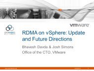
2.1 VMFS DATASTORES CONNECTED BY FIBRE CHANNEL OR ISCSI<br />
<strong>Virtual</strong> Machine File System (VMFS) Datastores are the most common method of deploying storage in<br />
<strong>VMware</strong> environments. VMFS is a clustered file system that allows LUNs to be accessed simultaneously by<br />
multiple ESX Servers running multiple VMs. The strengths of this solution are that it provides high<br />
performance <strong>and</strong> the technology is mature <strong>and</strong> well understood. In addition, VMFS provides the <strong>VMware</strong><br />
administrator with a fair amount of independence from the storage administrator, because once storage has<br />
been provisioned to the ESX Servers, the <strong>VMware</strong> administrator is free to use the storage as needed. Most<br />
data management operations are performed exclusively through <strong>VMware</strong> <strong>Virtual</strong>Center.<br />
The challenges associated with this storage design are focused around performance scaling <strong>and</strong> monitoring<br />
from the storage administrator’s perspective. Because Datastores fill the aggregated I/O dem<strong>and</strong>s of many<br />
VMs, this design doesn’t allow a storage array to identify the I/O load generated by an individual VM. The<br />
<strong>VMware</strong> administrator now has the role of I/O load monitoring <strong>and</strong> management, which has traditionally<br />
been h<strong>and</strong>led by storage administrators. <strong>VMware</strong> <strong>Virtual</strong>Center allows the administrator to collect <strong>and</strong><br />
analyze this data. <strong>NetApp</strong> extends the I/O data from <strong>Virtual</strong>Center by providing a mapping of physical<br />
storage to VMs, including I/O usage <strong>and</strong> physical path management, including VMDK to LUN mapping, with<br />
VMInsight. VMInsight is part of SANscreen ® from <strong>NetApp</strong>. Click here for more information about<br />
SANscreen.<br />
For information about accessing virtual disks stored on a VMFS by using either FC or iSCSI, see the<br />
<strong>VMware</strong> ESX Server 3.5 Configuration Guide.<br />
Figure 1) ESX Cluster connected to a VMFS Datastore via FC or iSCSI.<br />
5
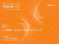
2.2 NAS DATASTORES CONNECTED OVER ETHERNET<br />
Support for storing virtual disks (VMDKs) on a network file system (NFS) was introduced with the release of<br />
<strong>VMware</strong> ESX 3.0. NFS Datastores are gaining in popularity as a method for deploying storage in <strong>VMware</strong><br />
environments. NFS allows volumes to be accessed simultaneously by multiple ESX Servers running multiple<br />
VMs. The strengths of this solution are similar to those of VMFS Datastores, as once storage has been<br />
provisioned to the ESX Servers the <strong>VMware</strong> administrator is free to use the storage as needed. Additional<br />
benefits of NFS Datastores include the lowest per-port costs (when compared to Fibre Channel solutions),<br />
high performance, <strong>and</strong> storage savings provided by <strong>VMware</strong> thin provisioning, which is the default format for<br />
VMDKs created on NFS.<br />
Of the Datastore options available with <strong>VMware</strong>, NFS Datastores provide the easiest means to integrate<br />
<strong>VMware</strong> with <strong>NetApp</strong>’s advanced data management <strong>and</strong> storage virtualization features such as productionuse<br />
data deduplication, array-based thin provisioning, direct access to array-based Snapshot copies, <strong>and</strong><br />
SnapRestore ® .<br />
The largest challenge associated with deploying this storage design is its lack of support with <strong>VMware</strong> Site<br />
Recovery Manager version 1.0. Customers looking for a business continuance solution will have to continue<br />
to use manual DR practices with NFS solutions until a future Site Recovery Manager update.<br />
Figure 2 shows an example of this configuration. Note that the storage layout appears much like that of a<br />
VMFS Datastore, yet each virtual disk file has its own I/O queue directly managed by the <strong>NetApp</strong> FAS<br />
system. For more information about storing VMDK files on NFS, see the <strong>VMware</strong> ESX Server 3.5<br />
Configuration Guide<br />
Figure 2) ESX Cluster connected to a NFS datastore.<br />
6
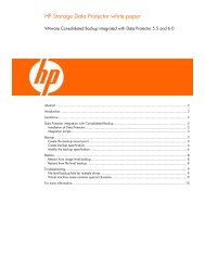
2.3 RAW DEVICE MAPPINGS WITH FIBRE CHANNEL OR ISCSI<br />
Support for raw device mapping (RDM) was introduced in <strong>VMware</strong> ESX Server 2.5. Unlike VMFS <strong>and</strong> NFS<br />
Datastores, which provide storage as a shared, global pool, RDMs provide LUN access directly to individual<br />
virtual machines. In this design, ESX acts as a connection proxy between the VM <strong>and</strong> the storage array. The<br />
core strength of this solution is support for virtual machine <strong>and</strong> physical-to-virtual-machine host-based<br />
clustering, such as Microsoft ® Cluster Server (MSCS). In addition, RDMs provide high individual disk I/O<br />
performance; easy disk performance measurement from a storage array; <strong>and</strong> easy integration with features<br />
of advanced storage systems such as SnapDrive ® , VM granular snapshots, SnapRestore, <strong>and</strong> FlexClone ® .<br />
The challenges of this solution are that <strong>VMware</strong> clusters may have to be limited in size, <strong>and</strong> this design<br />
requires ongoing interaction between storage <strong>and</strong> <strong>VMware</strong> administration teams. Figure 3 shows an<br />
example of this configuration. Note that each virtual disk file has a direct I/O to a dedicated LUN. This<br />
storage model is analogous to providing SAN storage to a physical server, except for the storage controller<br />
b<strong>and</strong>width, which is shared.<br />
RDMs are available in two modes; physical <strong>and</strong> virtual. Both modes support key <strong>VMware</strong> features such as<br />
VMotion, <strong>and</strong> can be used in both HA <strong>and</strong> DRS clusters. The key difference between the two technologies is<br />
the amount of SCSI virtualization that occurs at the VM level. This difference results in some limitations<br />
around MSCS <strong>and</strong> VMsnap use case scenarios. For more information about raw device mappings over<br />
Fibre Channel <strong>and</strong> iSCSI, see the <strong>VMware</strong> ESX Server 3.5 Configuration Guide.<br />
Figure 3) ESX Cluster with VMs connected to RDM LUNs via FC or iSCSI.<br />
7
2.4 DATASTORE COMPARISON TABLE<br />
Differentiating what is available with each type of Datastore <strong>and</strong> storage protocol can require considering<br />
many points. The following table compares the features available with each storage option. A similar chart<br />
for <strong>VMware</strong> is available in the <strong>VMware</strong> ESX Server 3i Configuration Guide<br />
Table 1) Datastore comparison.<br />
Capability/Feature FC iSCSI NFS<br />
Format VMFS or RDM VMFS or RDM <strong>NetApp</strong> WAFL®<br />
Max Datastores or<br />
LUNs<br />
256 256 32<br />
Max Datastore size 64TB 64TB 16TB<br />
Max running VMs per<br />
Datastore<br />
32 32 N/A<br />
Available link speeds 1, 2, 4, 8 Gb 1, 10 Gb 1, 10 Gb<br />
Backup Options<br />
VMDK image access VCB VCB VCB, VIC File Explorer<br />
VMDK file level access VCB, Windows® only VCB, Windows® only VCB or 3 rd party apps<br />
NDMP granularity Full LUN Full LUN Datastore, VMDK<br />
<strong>VMware</strong> Feature Support<br />
VMotion Yes Yes Yes<br />
<strong>Storage</strong> VMotion Yes Yes Experimental<br />
<strong>VMware</strong> HA Yes Yes Yes<br />
DRS Yes Yes Yes<br />
VCB Yes Yes Yes<br />
MSCS support Yes, via RDM Not supported Not supported<br />
Resize Datastore<br />
Yes, via extents<br />
Yes, via extents<br />
Yes, during production<br />
Not recommended in<br />
production<br />
Not recommended in<br />
production<br />
<strong>NetApp</strong> Integration Support<br />
Snapshot copies Yes Yes Yes<br />
SnapMirror® Datastore or RDM Datastore or RDM Datastore or VM<br />
SnapVault® Datastore or RDM Datastore or RDM Datastore or VM<br />
Data Deduplication Yes Yes Yes<br />
Thin provisioning Datastore or RDM Datastore or RDM Datastore<br />
FlexClone Datastore or RDM Datastore or RDM Datastore<br />
MultiStore® No Yes Yes<br />
SANscreen Yes plus VMInsight Yes plus VMInsight Yes<br />
Open Systems<br />
SnapVault<br />
Yes Yes Yes<br />
8
3 FAS CONFIGURATION AND SETUP<br />
3.1 STORAGE SYSTEM CONFIGURATION<br />
RAID DATA PROTECTION<br />
A byproduct of any consolidation effort is increased risk if the consolidation platform fails. As physical<br />
servers are converted to virtual machines <strong>and</strong> multiple VMs are consolidated onto a single physical platform,<br />
the impact of a failure to the single platform could be catastrophic. Fortunately, <strong>VMware</strong> provides multiple<br />
technologies that enhance availability of the virtual infrastructure. These technologies include physical<br />
server clustering via <strong>VMware</strong> HA, application load balancing with DRS, <strong>and</strong> the ability to non-disruptively<br />
move running VMs <strong>and</strong> data sets between physical ESX Servers with VMotion <strong>and</strong> <strong>Storage</strong> VMotion<br />
respectively.<br />
When focusing on storage availability, many levels of redundancy are available for deployments, including<br />
purchasing physical servers with multiple storage interconnects or HBAs, deploying redundant storage<br />
networking <strong>and</strong> network paths, <strong>and</strong> leveraging storage arrays with redundant controllers. A deployed storage<br />
design that meets all of these criteria can be considered to have eliminated all single points of failure.<br />
The reality is that data protection requirements in a virtual infrastructure are greater than those in a<br />
traditional physical server infrastructure. Data protection is a paramount feature of shared storage devices.<br />
<strong>NetApp</strong> RAID-DP ® is an advanced RAID technology that is provided as the default RAID level on all FAS<br />
systems. RAID-DP protects against the simultaneous loss of two drives in a single RAID group. It is very<br />
economical to deploy; the overhead with default RAID groups is a mere 12.5%. This level of resiliency <strong>and</strong><br />
storage efficiency makes data residing on RAID-DP safer than data stored on RAID 5 <strong>and</strong> more cost<br />
effective than RAID 10. <strong>NetApp</strong> recommends using RAID-DP on all RAID groups that store <strong>VMware</strong> data.<br />
AGGREGATES<br />
An aggregate is <strong>NetApp</strong>’s virtualization layer, which abstracts physical disks from logical data sets that are<br />
referred to as flexible volumes. Aggregates are the means by which the total IOPs available to all of the<br />
physical disks are pooled as a resource. This design is well suited to meet the needs of an unpredictable<br />
<strong>and</strong> mixed workload. <strong>NetApp</strong> recommends that whenever possible a small aggregate should be used as the<br />
root aggregate. This aggregate stores the files required for running <strong>and</strong> providing GUI management tools for<br />
the FAS system. The remaining storage should be placed into a small number of large aggregates. The<br />
overall disk I/O from <strong>VMware</strong> environments is traditionally r<strong>and</strong>om by nature, so this storage design gives<br />
optimal performance because a large number of physical spindles are available to service IO requests. On<br />
smaller FAS arrays, it may not be practical to have more than a single aggregate, due to the restricted<br />
number of disk drives on the system. In these cases, it is acceptable to have only a single aggregate.<br />
FLEXIBLE VOLUMES<br />
Flexible volumes contain either LUNs or virtual disk files that are accessed by <strong>VMware</strong> ESX Servers.<br />
<strong>NetApp</strong> recommends a one-to-one alignment of <strong>VMware</strong> Datastores to flexible volumes. This design offers<br />
an easy means to underst<strong>and</strong> the <strong>VMware</strong> data layout when viewing the storage configuration from the FAS<br />
array. This mapping model also makes it easy to implement Snapshot backups <strong>and</strong> SnapMirror replication<br />
policies at the Datastore level, because <strong>NetApp</strong> implements these storage side features at the flexible<br />
volume level.<br />
LUNS<br />
LUNs are units of storage provisioned from a FAS system directly to the ESX Servers. The ESX Server can<br />
access the LUNs in two ways. The first <strong>and</strong> most common method is as storage to hold virtual disk files for<br />
multiple virtual machines. This type of usage is referred to as a VMFS Datastore. The second method is as a<br />
raw device mapping (RDM). With RDM, the ESX Server accesses the LUN, which in turn passes access<br />
directly to a virtual machine for use with its native file system, such as NTFS or EXT3. For more information,<br />
see the <strong>VMware</strong> <strong>Storage</strong>/SAN Compatibility Guide for ESX Server 3.5 <strong>and</strong> ESX Server 3i<br />
9
STORAGE NAMING CONVENTIONS<br />
<strong>NetApp</strong> storage systems allow human or canonical naming conventions. In a well-planned virtual<br />
infrastructure implementation, a descriptive naming convention aids in identification <strong>and</strong> mapping through<br />
the multiple layers of virtualization from storage to the virtual machines. A simple <strong>and</strong> efficient naming<br />
convention also facilitates configuration of replication <strong>and</strong> disaster recovery processes.<br />
Consider the following suggestions:<br />
• FlexVol name: Matches the Datastore name or a combination of the Datastore name <strong>and</strong> the<br />
replication policy; for example, Datstore1 or Datastore1_4hr_mirror.<br />
• LUN name for VMFS: <strong>NetApp</strong> suggests matching the name of the Datastore.<br />
LUN name for RDMs: Should be the host name <strong>and</strong> volume name of the VM; for example, with a<br />
Windows VM, hostname_c_drive.lun; or with a Linux ® VM, hostname_root.lun,<br />
4 VIRTUAL INFRASTRUCTURE 3 CONFIGURATION BASICS<br />
4.1 CONFIGURATION LIMITS AND RECOMMENDATIONS<br />
When sizing storage, you should be aware of the following limits <strong>and</strong> recommendations.<br />
NETAPP VOLUME OPTIONS<br />
<strong>NetApp</strong> flexible volumes should be configured with the snap reserve set to 0 <strong>and</strong> the default Snapshot<br />
schedule disabled. All <strong>NetApp</strong> Snapshot copies must be coordinated with the ESX Servers for data<br />
consistency. <strong>NetApp</strong> Snapshot copies are discussed in section 10.1, “Implementing Snapshot Copies.” To<br />
set the volume options for Snapshot copies to the recommended setting, enter the following comm<strong>and</strong>s in<br />
the FAS system console.<br />
1. Log into the <strong>NetApp</strong> console.<br />
2.<br />
3.<br />
Set the volume Snapshot schedule:<br />
snap sched 0 0 0<br />
Set the volume Snapshot reserve: c<br />
snap reserve 0<br />
RDMS AND VMWARE CLUSTER SIZING<br />
Currently, a <strong>VMware</strong> cluster is limited to a total of 256 LUNs per ESX Server, which for practical purposes<br />
extends this limit to a data center. This limitation typically comes into consideration only with RDM-based<br />
deployments. With RDMs, you must plan for the use of a VFMS datastore to store virtual machine<br />
configuration files. Note that the VMDK definition file associated with RDMs is reported to be the same size<br />
as the LUN. This is the default behavior in the <strong>Virtual</strong>Center; the actual VMDK definition file consumes only<br />
a few megabytes of disk storage (typically between 1 <strong>and</strong> 8 megabytes, the block sizes available with<br />
VMFS).<br />
Based on LUN limits, the following formula can be used to determine the maximum number of ESX nodes<br />
per ESX cluster. Note: this formula implies that all nodes in a cluster are connected to all shared LUNs.<br />
254 / (number of RDMS per VM) / (planned number of VMs per ESX host) = number of ESX nodes in a<br />
data center<br />
For example, if you plan to run 20 VMs per ESX Server <strong>and</strong> want to assign 2 RDMs per VM, the formula is:<br />
254/20/2 = 6.4 rounded up = 7 ESX Servers in the cluster<br />
10
LUN SIZING FOR VMFS DATASTORES<br />
VMFS Datastores offer the simplest method of provisioning storage; however, it’s necessary to balance the<br />
number of Datastores to be managed with the possibility of overloading very large Datastores with too many<br />
VMs. In the latter case, the I/O load must be leveled. <strong>VMware</strong> provides <strong>Storage</strong> VMotion as a means to<br />
redistribute VM storage to alternative Datastores without disruption to the VM. It is common for large VMFS<br />
Datastores to have hit their IO performance limit before their capacity limit has been reached. Advanced<br />
storage technologies like thin provisioning can return provisioned but unused storage back to the FAS<br />
storage pool for reuse.<br />
Unused storage does not include storage that contains data that has been deleted or migrated as part of a<br />
<strong>Storage</strong> VMotion process. Although there is no definitive recommendation, a commonly deployed size for a<br />
VMFS Datastore is somewhere between 300 <strong>and</strong> 700GB. The maximum supported LUN size is 2TB. For<br />
more information, see the <strong>VMware</strong> <strong>Storage</strong>/SAN Compatibility Guide for ESX Server 3.5 <strong>and</strong> ESX Server 3i.<br />
NFS DATASTORE LIMITS<br />
By default, <strong>VMware</strong> ESX allows 8 NFS datastores; this limit can be increased to 32. As <strong>Virtual</strong><br />
<strong>Infrastructure</strong>s tend to exp<strong>and</strong> over time deployments, <strong>NetApp</strong> recommends that you increase this value to<br />
meet your future infrastructure needs <strong>and</strong> ensure system availability.<br />
To make this change, follow these steps from within the <strong>Virtual</strong> <strong>Infrastructure</strong> client. For more information on<br />
this process, including the requirement to reboot the ESX server, please refer to <strong>VMware</strong> KB 2239: NFS<br />
Mounts are Restricted to 8 by Default.<br />
1 Open <strong>Virtual</strong>Center.<br />
2 Select an ESX host.<br />
3 In the right pane, select the Configuration tab.<br />
4 In the Software box, select Advanced Configuration.<br />
5 In the pop-up window, left pane, select NFS.<br />
6 Change the value of NFS.MaxVolumes to 32 (see Figure 4).<br />
7 In the pop-up window, left pane, select Net.<br />
8 Change the value of Net.TcpIpHeapSize to 30.<br />
9 Change the value of Net.TcpIpHeapMax to 120.<br />
10 Repeat the steps for each ESX Server.<br />
11
Figure 4) Increasing the number of NFS Datastores.<br />
ADDITIONAL NFS RECOMMENDATIONS<br />
When deploying VMDKs on NFS, enable the following setting for optimal performance. To make this<br />
change, follow these steps from within the FAS system console.<br />
1 Log in to the <strong>NetApp</strong> console.<br />
2<br />
From the storage appliance console, run<br />
vol options no_atime_update on<br />
3 Repeat step 2 for each NFS volume.<br />
4 From the console, enter options nfs.tcp.recvwindowsize 64240<br />
<strong>VMware</strong> ESX Server provides a snapshot mechanism. The process to delete a <strong>VMware</strong> snapshot (or<br />
commit the VMsnap log files) can encounter an issue where the I/O of a GOS is suspended for an extended<br />
period of time when the Datastores are connected by NFS.<br />
<strong>VMware</strong> snapshots are being used for virtual machines on the NFS Datastores. This usage includes, but is<br />
not limited to <strong>VMware</strong> Snapshots, <strong>Storage</strong> VMotion, Consolidated Backup, <strong>NetApp</strong> SnapManager for <strong>Virtual</strong><br />
<strong>Infrastructure</strong>, etc.<br />
This behavior has been identified by <strong>VMware</strong> as SR195302591. This issue is resolved in ESX 3.5 update 3;<br />
however, additional steps must be completed in order to enable this fix. A patch has been created to<br />
address this issue with systems running ESX 3.5 update 1 or update 2. NOTE: When patch ESX350-<br />
12
200808401-BG is in use, there are conditions where virtual machine may get powered off unexpectedly.<br />
These are:<br />
1. 3rd party clients, such as virtual machine management agents, which use 'read-only' lock on virtual<br />
disk files during the <strong>VMware</strong> snapshot commit process.<br />
2. A user manually creates snapshot on the virtual machine virtual while it is in the process of<br />
committing an existing <strong>VMware</strong> snapshot.<br />
In order to avoid these behaviors, turn off 3rd party clients during the <strong>VMware</strong> snapshot commit process<br />
to avoid the issue described above.<br />
PATCH PROCESS FOR SYSTEMS RUNNING ESX AND ESXI 3.5 UPDATE 3:<br />
1 Using VMotion migrate the running VMs to other ESX nodes<br />
2 Place the ESX server identified in step two into maintenance mode<br />
3 Ensure the advanced configuration option for disabling NFS locks is set to 0<br />
4 Backup the /etc/vmware/config file<br />
5<br />
Insert the following line into the /etc/vmware/config file<br />
prefvmx.consolidateDeleteNFSLocks = “TRUE”<br />
6 Reboot the ESX server<br />
7 After the reboot completes, login <strong>and</strong> exit maintenance mode<br />
8<br />
Migrate a VM back to the patched ESX server & verify the creation of a lock file in the<br />
root directory of this VM. Lock files have the following file extension: .lck<br />
9 If the lock file is created repeat steps 1 thru 7 on each ESX server<br />
10<br />
If the lock file is not created please ensure you followed every step in this process. If a<br />
lock is still not created, the VM ay require to be restarted<br />
The following subset is a single process that streamlines some of the patching process. It requires one to<br />
log into an ESX server via the CLI. It replaces steps 2 thru 6 from the previous process. The following 5<br />
lines must be run from the console of the ESX server as root.<br />
1 vimsh -n -e /hostsvc/maintenance_mode_enter<br />
2 esxcfg-advcfg -s 0 /NFS/LockDisable<br />
3 cp –p /etc/vmware/config /etc/vmware/config.bak<br />
4 echo prefvmx.consolidateDeleteNFSLocks = “TRUE”’ >> /etc/vmware/config<br />
5 reboot<br />
After this process complete steps 7 thru 10 from the process to patch ESX 3.5 update 3 systems.<br />
13
PATCH PROCESS FOR SYSTEMS RUNNING ESX AND ESXI 3.5 UPDATE 1 OR UPDATE 2:<br />
1 Download patch ESX350-200808401-BG<br />
2<br />
Identify an ESX server(s) to apply the patch to <strong>and</strong> ensure the systems the<br />
requirements of the patch<br />
3 Install the patch<br />
4 Using VMotion migrate the running VMs to other ESX nodes<br />
5 Place the ESX server identified in step two into maintenance mode<br />
6 Ensure the advanced configuration option for disabling NFS locks is set to 0<br />
7 Backup the /etc/vmware/config file<br />
8<br />
Insert the following line into the /etc/vmware/config file<br />
prefvmx.consolidateDeleteNFSLocks = “TRUE”<br />
9 Reboot the ESX server<br />
10 After the reboot completes, login <strong>and</strong> exit maintenance mode<br />
11<br />
Migrate a VM back to the patched ESX server & verify the creation of a lock file in the<br />
root directory of this VM. Lock files have the following file extension: .lck<br />
12 If the lock file is created repeat steps 2 thru 10 on each ESX server requiring the patch<br />
13<br />
If the lock file is not created please ensure you followed every step in this process. If a<br />
lock is still not created, the VM ay require to be restarted<br />
The following subset is a single process that streamlines some of the patching process. It requires one to<br />
log into an ESX server via the CLI. It replaces steps 5 thru 9 from the previous process. The following 5<br />
lines must be run from the console of the ESX server as root.<br />
1 vimsh -n -e /hostsvc/maintenance_mode_enter<br />
2 esxcfg-advcfg -s 0 /NFS/LockDisable<br />
3 cp –p /etc/vmware/config /etc/vmware/config.bak<br />
4 echo prefvmx.consolidateDeleteNFSLocks = “TRUE”’ >> /etc/vmware/config<br />
5 reboot<br />
After this process complete steps 10 thru 13 from the process to patch ESX 3.5 update 1 <strong>and</strong> update 2<br />
systems.<br />
CONSIDERATIONS FOR SYSTEMS RUNNING VERSIONS OF ESX OR ESXI PRIOR TO 3.5 UPDATE 1:<br />
If you are using scripts in order to take on disk snapshot backups <strong>and</strong> are unable to upgrade your systems,<br />
then <strong>VMware</strong> <strong>and</strong> <strong>NetApp</strong> recommend that you discontinue the use of the VMsnap process prior to<br />
executing the <strong>NetApp</strong> snapshot.<br />
14
VIRTUAL DISK STARTING PARTITION OFFSETS<br />
<strong>Virtual</strong> machines store their data on virtual disks. As with physical disks, these disks are formatted with a file<br />
system. When formatting a virtual disk, make sure that the file systems of the VMDK, the Datastore, <strong>and</strong> the<br />
storage array are in proper alignment. Misalignment of the VM’s file system can result in degraded<br />
performance. However, even if file systems are not optimally aligned, performance degradation may not be<br />
experienced or reported, based on the I/O load relative to the ability of the storage arrays to serve the I/O,<br />
as well as the overhead for being misaligned. Every storage vendor provides values for optimal block-level<br />
alignment from VM to the array. For details, see the <strong>VMware</strong> publication Recommendations for Aligning<br />
VMFS Partitions.<br />
When aligning the partitions of virtual disks for use with <strong>NetApp</strong> FAS systems, the starting partition offset<br />
must be divisible by 4096. The recommended starting offset value for Windows 2000, 2003, & XP operating<br />
systems is 32768. Windows 2008 & Vista default at 1048576 <strong>and</strong> does not require any adjustments.<br />
To verifying this value run msinfo32, <strong>and</strong> you will typically find that the VM is running with a default starting<br />
offset value of 32256 (see Figure 5). To run msinfo32, select Start > All Programs > Accessories > System<br />
Tools > System Information.<br />
Figure 5) Using system information to identify the starting partition offset.<br />
Correcting the starting offset is best addressed by correcting the template from which new VMs are<br />
provisioned. For currently running VMs that are misaligned, <strong>NetApp</strong> recommends correcting the offset only<br />
of VMs that are experiencing an I/O performance issue. This performance penalty is more noticeable on<br />
systems that are completing a large number of small read <strong>and</strong> write operations. The reason for this<br />
recommendation is that in order to correct the partition offset, a new virtual disk has to be created <strong>and</strong><br />
formatted, <strong>and</strong> the data from the VM has to be migrated from the original disk to the new one. Misaligned<br />
VMs with low I/O requirements do not benefit from these efforts.<br />
15
FORMATTING WITH THE CORRECT STARTING PARTITION OFFSETS<br />
<strong>Virtual</strong> disks can be formatted with the correct offset at the time of creation by simply booting the VM before<br />
installing an operating system <strong>and</strong> manually setting the partition offset. For Windows guest operating<br />
systems, consider using the Windows Preinstall Environment boot CD or alternative tools like Bart’s PE CD.<br />
To set up the starting offset, follow these steps <strong>and</strong> see Figure 6.<br />
1. Boot the VM with the WinPE CD.<br />
2. Select Start > Run <strong>and</strong> enter DISKPART..<br />
3. Enter Select Disk0.<br />
4. Enter Create Partition Primary Align=32.<br />
5. Reboot the VM with WinPE CD.<br />
6. Install the operating system as normal.<br />
Figure 6) Running diskpart to set a proper starting partition offset.<br />
OPTIMIZING WINDOWS FILE SYSTEM FOR OPTIMAL IO PERFORMANCE<br />
If your virtual machine is not acting a file server you may want to consider implementing the following<br />
change to your virtual machines which disables the access time updates process in NTFS. This change will<br />
reduce the amount of IOPs occurring within the file system. To make this change complete the following<br />
steps.<br />
1. Log into a Windows VM<br />
2. Select Start > Run <strong>and</strong> enter CMD<br />
3. Enter fsutil behavior set disablelastaccess 1<br />
16
4.2 STORAGE PROVISIONING<br />
<strong>VMware</strong> <strong>Virtual</strong> <strong>Infrastructure</strong> 3.5 introduced several new storage options. This section covers storage<br />
provisioning for Fibre Channel, iSCSI, <strong>and</strong> NFS.<br />
VMWARE REQUIREMENT FOR FIBRE CHANNEL AND ISCSI<br />
<strong>VMware</strong> has identified a bug which impacts the stability of hosts connect via FC & iSCSI, <strong>and</strong> has released<br />
patch ESX350-200808402-BG, which addresses this bug. At present time, this patch applies to ESX<br />
version 3.5, updates 1 <strong>and</strong> 2 only.<br />
FIBRE CHANNEL AND ISCSI LUN PROVISIONING<br />
When provisioning LUNs for access via FC or iSCSI, the LUNs must be masked so that the appropriate<br />
hosts can connect only to them. With a <strong>NetApp</strong> FAS system, LUN masking is h<strong>and</strong>led by the creation of<br />
initiator groups. <strong>NetApp</strong> recommends creating an igroup for each <strong>VMware</strong> cluster. <strong>NetApp</strong> also recommends<br />
including in the name of the igroup the name of the cluster <strong>and</strong> the protocol type (for example, DC1_FC <strong>and</strong><br />
DC1_iSCSI). This naming convention <strong>and</strong> method simplify the management of igroups by reducing the total<br />
number created. It also means that all ESX Servers in the cluster see each LUN at the same ID. Each<br />
initiator group includes all of the FC worldwide port names (WWPNs) or iSCSI qualified names (IQNs) of the<br />
ESX Servers in the <strong>VMware</strong> cluster.<br />
Note: If a cluster will use both Fibre Channel <strong>and</strong> iSCSI protocols, separate igroups must be created for<br />
Fibre Channel <strong>and</strong> iSCSI.<br />
For assistance in identifying the WWPN or IQN of the ESX Server, select <strong>Storage</strong> Adapters on the<br />
Configuration tab for each ESX Server in <strong>Virtual</strong>Center <strong>and</strong> refer to the SAN Identifier column (see Figure 7).<br />
Figure 7) Identifying WWPN <strong>and</strong> IQN numbers in the <strong>Virtual</strong> <strong>Infrastructure</strong> client.<br />
LUNs can be created by using the <strong>NetApp</strong> LUN Wizard in the FAS system console or by using the<br />
FilerView ® GUI, as shown in the following procedure.<br />
1. Log in to FilerView.<br />
2. Select LUNs.<br />
3. Select Wizard.<br />
4. In the Wizard window, click Next.<br />
5. Enter the path (see Figure 8).<br />
6. Enter the LUN size.<br />
7. Enter the LUN type (for VMFS select <strong>VMware</strong>; for RDM select the VM type).<br />
8. Enter a description <strong>and</strong> click Next.<br />
17
Figure 8) <strong>NetApp</strong> LUN Wizard.<br />
The next step in the LUN Wizard is LUN masking, which is accomplished by assigning an igroup to a LUN.<br />
With the LUN Wizard, you can either assign an existing igroup or create a new igroup.<br />
Important: The ESX Server expects a LUN ID to be the same on every node in an ESX cluster. Therefore<br />
<strong>NetApp</strong> recommends creating a single igroup for each cluster rather than for each ESX Server.<br />
To configure LUN masking on a LUN created in the FilerView GUI, follow these steps.<br />
1. Select Add Group.<br />
2.<br />
3a.<br />
3b.<br />
4.<br />
Select the Use Existing Initiator Group radio button. Click Next <strong>and</strong> proceed to step<br />
3a.<br />
Or<br />
Select the Create a New Initiator Group radio button. Click Next <strong>and</strong> proceed to step<br />
3b.<br />
Select the group from the list <strong>and</strong> either assign a LUN ID or leave the field blank (the<br />
system will assign an ID). Click Next to complete the task.<br />
Supply the igroup parameters, including name, connectivity type (FC or iSCSI), <strong>and</strong><br />
OS type (<strong>VMware</strong>), <strong>and</strong> then click Next (see Figure 9).<br />
For the systems that will connect to this LUN, enter the new SAN identifiers or select<br />
the known identifiers (WWPN or IQN).<br />
5. Click the Add Initiator button.<br />
6. Click Next to complete the task.<br />
18
Figure 9) Assigning an igroup to a LUN.<br />
4.3 NETWORK FILE SYSTEM (NFS) PROVISIONING<br />
To create a file system for use as an NFS Datastore, follow these steps.<br />
1 Open FilerView (http://filer/na_admin).<br />
2 Select Volumes.<br />
3 Select Add to open the Volume Wizard (see Figure 10). Complete the Wizard.<br />
4 From the FilerView menu, select NFS.<br />
5<br />
Select Add Export to open the NFS Export Wizard (see Figure 11). Complete the wizard<br />
for the newly created file system, granting read/write <strong>and</strong> root access to the VMkernel<br />
address of all ESX hosts that will connect to the exported file system.<br />
6 Open <strong>Virtual</strong>Center.<br />
7 Select an ESX host.<br />
8 In the right pane, select the Configuration tab.<br />
9 In the Hardware box, select the <strong>Storage</strong> link.<br />
10<br />
In the upper right corner, click Add <strong>Storage</strong> to open the Add <strong>Storage</strong> Wizard (see Figure<br />
12).<br />
11 Select the Network File System radio button <strong>and</strong> click Next.<br />
12<br />
Enter a name for the storage appliance, export, <strong>and</strong> Datastore, then click Next (see<br />
Figure 13).<br />
13 Click Finish.<br />
19
Figure 10) <strong>NetApp</strong> Volume Wizard.<br />
Figure 11) <strong>NetApp</strong> NFS Export Wizard.<br />
20
Figure 12) <strong>VMware</strong> Add <strong>Storage</strong> Wizard.<br />
21
Figure 13) <strong>VMware</strong> Add <strong>Storage</strong> Wizard NFS configuration.<br />
ESX 3.5 HOST<br />
For optimal availability with NFS Datastores, <strong>NetApp</strong> recommends making the following changes on each<br />
ESX 3.5 host.<br />
1 Open <strong>Virtual</strong>Center.<br />
2 Select an ESX host.<br />
3 In the right pane, select the Configuration tab.<br />
4 In the Software box, select Advanced Configuration.<br />
5 In the pop-up window, left pane, select NFS.<br />
6 Change the value of NFS.HeartbeatFrequency to 12.<br />
7 Change the value of NFS.HeartbeatMaxFailures to 10.<br />
8 Repeat for each ESX Server.<br />
22
ESX 3.0 HOST<br />
For optimal availability with NFS Datastores, <strong>NetApp</strong> recommends making the following changes on each<br />
ESX 3.0.x host.<br />
1 Open <strong>Virtual</strong>Center.<br />
2 Select an ESX host.<br />
3 In the right pane, select the Configuration tab.<br />
4 In the Software box, select Advanced Configuration.<br />
5 In the pop-up window, left pane, select NFS.<br />
6 Change the value of NFS.HeartbeatFrequency to 5 from 9.<br />
7 Change the value of NFS.HeartbeatMaxFailures to 25 from 3.<br />
8 Do not change the value for NFS.HeartbeatTimeout (the default is 5).<br />
9 Repeat for each ESX Server.<br />
4.4 STORAGE CONNECTIVITY<br />
This section covers the available storage options with ESX 3.5 <strong>and</strong> reviews the settings that are specific to<br />
each technology.<br />
FIBRE CHANNEL CONNECTIVITY<br />
The Fibre Channel service is the only storage protocol that is running by default on the ESX Server. <strong>NetApp</strong><br />
recommends that each ESX Server have two FC HBA ports available for storage connectivity, or at a<br />
minimum one FC HBA port <strong>and</strong> an iSCSI (software- or hardware-based) port for storage path redundancy.<br />
To connect to FC LUNs provisioned on a FAS system, follow these steps.<br />
1 Open <strong>Virtual</strong>Center.<br />
2 Select an ESX host.<br />
3 In the right pane, select the Configuration tab.<br />
4 In the Hardware box, select the <strong>Storage</strong> Adapters link.<br />
5 In the upper right corner, select the Rescan link.<br />
6 Repeat steps 1 through 5 for each ESX Server in the cluster.<br />
Selecting Rescan forces the rescanning of all HBAs (FC <strong>and</strong> iSCSI) to discover changes in the storage<br />
available to the ESX Server.<br />
Note: Some FC HBAs require you to scan them twice to detect new LUNs (see <strong>VMware</strong> kb1798). After the<br />
LUNs have been identified, they can be assigned to a virtual machine as raw device mapping or provisioned<br />
to the ESX Server as a datastore.<br />
23
To add a LUN as a Datastore, follow these steps.<br />
1 Open <strong>Virtual</strong>Center.<br />
2 Select an ESX host.<br />
3 In the right pane, select the Configuration tab.<br />
4<br />
In the Hardware box, select the <strong>Storage</strong> link <strong>and</strong> then click Add <strong>Storage</strong> to open the Add<br />
<strong>Storage</strong> Wizard (see Figure 14).<br />
5 Select the Disk/LUN radio button <strong>and</strong> click Next.<br />
6 Select the LUN to use <strong>and</strong> click Next.<br />
7 Enter a name for the Datastore <strong>and</strong> click Next.<br />
8 Select the block size, click Next, <strong>and</strong> click Finish.<br />
Figure 14) <strong>VMware</strong> Add <strong>Storage</strong> wizard.<br />
24
The default block size of a <strong>Virtual</strong> Machine File System is 1MB. This block size supports storing virtual disk<br />
files up to a maximum of 256GB in size. If you plan to store virtual disks larger than 256GB in the datastore,<br />
you must increase the block size to be greater than the default (see Figure 15).<br />
Figure 15) Formatting a LUN with VMFS.<br />
ISCSI/IP SAN CONNECTIVITY<br />
As a best practice <strong>NetApp</strong> recommends separating IP based storage traffic from public IP network traffic by<br />
implementing separate physical network segments or VLAN segments. This design protects the b<strong>and</strong>width<br />
available to the storage network in a similar the manner as SCSI or FC data is not impacted by public IP<br />
traffic.<br />
To create a second network in ESX requires one to create a second vSwitch other than the one used for<br />
virtual machine traffic. To enable IP base storage connectivity, the ESX Server requires a VMkernel port do<br />
be defined on this vSwitch. <strong>NetApp</strong> recommends that each ESX Server should have a service console port<br />
defined on the vSwitch that transmits public <strong>Virtual</strong> Machine traffic <strong>and</strong> on the vSwitch configured for IP<br />
storage traffic. This second service console port adds the redundancy in ESX HA architectures.<br />
An added layer of security can be added to an IP storage network by not allowing the routing of traffic from<br />
public networks with the storage network. If your network is designed in this manner please note that the<br />
service console port on the storage network will only provide redundancy for ESX HA events. It will not<br />
provide ESX management access in the event of complete loss to the service console port on the public<br />
network.<br />
IP storage network, or VMkernel, connectivity can be verified by the use of the vmkping comm<strong>and</strong>. With<br />
iSCSI connected LUNs the syntax to test connectivity is vmkping .<br />
25
To configure the iSCSI connectivity, follow these steps.<br />
1 Open <strong>Virtual</strong>Center.<br />
2 Select an ESX host.<br />
3 In the right pane, select the Configuration tab.<br />
4 In the Hardware box, select Networking.<br />
5<br />
In the upper right corner, click Add Networking to open the Add Network Wizard (see<br />
Figure 16).<br />
6 Select the VMkernel radio button <strong>and</strong> click Next.<br />
7<br />
Either select an existing vSwitch or create a new one.<br />
Note: If a separate iSCSI network does not exist, create a new vSwitch.<br />
8 Click Next.<br />
9<br />
10<br />
Enter the IP address <strong>and</strong> subnet mask, click Next, <strong>and</strong> then click Finish to close the Add<br />
Network Wizard (see Figure 17).<br />
Optional: A default gateway is not required for the VMkernel IP storage network. (see<br />
Figure 17).<br />
11 In the Configuration tab, left pane, select Security Profile.<br />
12 In the right pane, select the Properties link to open the Firewall Properties window.<br />
13<br />
Select the Software iSCSI Client checkbox <strong>and</strong> then click OK to close the Firewall<br />
Properties window (see Figure 18).<br />
14 In the right pane, Hardware box, select <strong>Storage</strong> Adapters.<br />
15<br />
Highlight the iSCSI Adapter <strong>and</strong> click the Properties link in the Details box (see Figure<br />
19).<br />
16 Select the Dynamic Discovery tab in the iSCSI Initiator Properties box.<br />
17<br />
18<br />
Click Add <strong>and</strong> enter the IP address of the iSCSI-enabled interface on the <strong>NetApp</strong> FAS<br />
system (see Figure 20).<br />
For an additional layer of security, select the CHAP tab to configure CHAP<br />
authentication. <strong>NetApp</strong> recommends setting up <strong>and</strong> verifying iSCSI access before<br />
enabling CHAP authentication.<br />
26
Figure 16) Adding a VMkernel port.<br />
27
Figure 17) Configuring a VMkernel port.<br />
28
Figure 18) Configuring the firewall in ESX.<br />
Figure19) Selecting an iSCSI initiator.<br />
29
Figure 20) Configuring iSCSI dynamic discovery.<br />
If you are not ready to use iSCSI for your primary data access, you can consider it for several other uses.<br />
iSCSI can be used to connect to Datastores that store CD-ROM ISO images. Also, it can be used as a<br />
redundant or failover path for a primary Fibre Channel path. If you are using this setup, you must configure<br />
LUN multipathing. See “<strong>NetApp</strong> Fibre Channel Multipathing,” later in this section. In addition by installing<br />
iSCSI HBAs into one’s ESX servers allows these servers to boot from an iSCSI IP SAN (or boot from SAN).<br />
NFS CONNECTIVITY<br />
As a best practice <strong>NetApp</strong> recommends separating IP based storage traffic from public IP network traffic by<br />
implementing separate physical network segments or VLAN segments. This design protects the b<strong>and</strong>width<br />
available to the storage network in a similar the manner as FC connected or SCSI attached data is not<br />
impacted by public IP traffic.<br />
To create a second network in ESX requires one to create a second vSwitch other than the one used for<br />
virtual machine traffic. To enable IP base storage connectivity, the ESX Server requires a VMkernel port do<br />
be defined on this vSwitch. <strong>NetApp</strong> recommends that each ESX Server should have a service console port<br />
defined on the vSwitch that transmits public <strong>Virtual</strong> Machine traffic <strong>and</strong> on the vSwitch configured for IP<br />
storage traffic. This second service console port adds the redundancy in ESX HA architectures.<br />
An added layer of security can be added to an IP storage network by not allowing the routing of traffic from<br />
public networks with the storage network. If your network is designed in this manner please note that the<br />
service console port on the storage network will only provide redundancy for ESX HA events. It will not<br />
provide ESX management access in the event of complete loss to the service console port on the public<br />
network.<br />
IP storage network, or VMkernel, connectivity can be verified by the use of the vmkping comm<strong>and</strong>. With<br />
NFS connected datastores the syntax to test connectivity is vmkping .<br />
30
NETAPP FIBRE CHANNEL MULTIPATHING<br />
<strong>NetApp</strong> clustered FAS systems have an option known as cfmode, which controls the behavior of the<br />
system’s Fibre Channel ports if a cluster failover occurs. If you are deploying a clustered solution that<br />
provides storage for a <strong>VMware</strong> cluster, you must make sure that cfmode is set to either St<strong>and</strong>by or Single<br />
System Image. Single System Image mode is the preferred setting. For a complete list of supported ESX FC<br />
configurations, see the <strong>NetApp</strong> SAN Support Matrix. To verify the current cfmode, follow these steps.<br />
1 Connect to the FAS system console (via either SSH, Telnet, or Console connection).<br />
2 Enter fcp show cfmode.<br />
3 If cfmode needs to be changed, enter FC set cfmode .<br />
St<strong>and</strong>by cfmode may require more switch ports, because the multipathing failover is h<strong>and</strong>led by the FAS<br />
system <strong>and</strong> is implemented with active/inactive ports. Single System Image requires additional multipathing<br />
configuration on the <strong>VMware</strong> server. For more information about the different cfmodes available <strong>and</strong> the<br />
impact of changing a cfmode, see section 8 in the Data ONTAP Block Management Guide.<br />
VMWARE FIBRE CHANNEL AND ISCSI MULTIPATHING<br />
If you have implemented Single System Image cfmode, then you must configure ESX multipathing. When<br />
you are using multipathing, <strong>VMware</strong> requires the default path to be selected for each LUN connected on<br />
each ESX Server. To set the paths, follow these steps.<br />
1 Open <strong>Virtual</strong>Center.<br />
2 Select an ESX Server.<br />
3 In the right pane, select the Configuration tab.<br />
4 In the Hardware box, select <strong>Storage</strong>.<br />
5 In the <strong>Storage</strong> box, highlight the storage <strong>and</strong> select the Properties link (see Figure 21).<br />
6 In the Properties dialog box, click the Manage Paths button.<br />
7<br />
8<br />
Identify the path to set as the primary active path <strong>and</strong> click the Change button (See<br />
Figure 22).<br />
In the Change Path State window, select the path as Preferred <strong>and</strong> Enabled <strong>and</strong> click<br />
OK (See Figure 23).<br />
Figure 21) Selecting a Datastore.<br />
31
Figure 22) <strong>VMware</strong> Manage Paths dialog box.<br />
Figure 23) Setting path preferences.<br />
An alternative method for setting the preferred path for multiple LUNs is available in <strong>Virtual</strong>Center. To set the<br />
path, follow these steps.<br />
1 Open <strong>Virtual</strong>Center.<br />
2 Select an ESX Server.<br />
3 In the right pane, select the Configuration tab.<br />
4 In the Hardware box, select <strong>Storage</strong> Adapters.<br />
5 In the <strong>Storage</strong> Adapters pane, select a host bus adapter.<br />
6 Highlight all of the LUNs to configure.<br />
7 Right-click the highlighted LUNs <strong>and</strong> select Manage Paths (see Figure 24).<br />
8<br />
In the Manage Paths window, set the multipathing policy <strong>and</strong> preferred path for all of the<br />
highlighted LUNs (see Figure 25).<br />
32
Figure 24) Bulk selecting SCSI targets.<br />
Figure 25) Setting a preferred path.<br />
MANAGING MULTIPATHING WITH NETAPP ESX HOST UTILITIES<br />
<strong>NetApp</strong> provides a utility for simplifying the management of ESX nodes on FC SAN. This utility is a collection<br />
of scripts <strong>and</strong> executables that is referred to as the FC ESX Host Utilities for Native OS. <strong>NetApp</strong> highly<br />
recommends using this kit to configure optimal settings for FC HBAs.<br />
One of the components of the Host Utilities is a script called config_mpath. This script reduces the<br />
administrative overhead of managing SAN LUN paths by using the procedures previously described. The<br />
config_mpath script determines the desired primary paths to each of the SAN LUNs on the ESX Server <strong>and</strong><br />
then sets the preferred path for each LUN to use one of the primary paths. Simply running the config_mpath<br />
script once on each ESX Server in the cluster can complete multipathing configuration for large numbers of<br />
LUNs quickly <strong>and</strong> easily. If changes are made to the storage configuration, the script is simply run an<br />
additional time to update the multipathing configuration based on the changes to the environment.<br />
33
Other notable components of the FC ESX Host Utilities for Native OS are the config_hba script, which sets<br />
the HBA timeout settings <strong>and</strong> other system tunables required by the <strong>NetApp</strong> storage device, <strong>and</strong> a collection<br />
of scripts used for gathering system configuration information in the event of a support issue.<br />
For more information about the FC ESX Host Utilities for Native OS, see the <strong>NetApp</strong> SAN/iSAN compatibility<br />
guide<br />
5 IP STORAGE NETWORKING BEST PRACTICES<br />
<strong>NetApp</strong> recommends using dedicated resources for storage traffic whenever possible. With IP storage<br />
networks, this can be achieved with separate physical switches or logically by implementing VLAN segments<br />
for storage I/O on a shared, switched IP infrastructure.<br />
10 GB ETHERNET<br />
<strong>VMware</strong> ESX 3 <strong>and</strong> ESXi 3 introduced support for 10 Gb Ethernet. An advantage of 10 GbE is the ability to<br />
reduce the number of network ports in the infrastructure, especially but not limited to, blade servers. To<br />
verify support for your hardware <strong>and</strong> its use for storage I/O, see the ESX I/O compatibility guide<br />
VLAN IDS<br />
When segmenting network traffic with VLANs, interfaces can either be dedicated to a single VLAN or they<br />
can support multiple VLANs with VLAN tagging.<br />
For systems that have fewer NICs, such as blade servers, VLANs can be very useful. Channeling two NICs<br />
together provides an ESX server with physical link redundancy. By adding multiple VLANs, one can group<br />
common IP traffic onto separate VLANs for optimal performance. It is recommended to group Service<br />
console access with the <strong>Virtual</strong> Machine Network on one VLAN, <strong>and</strong> on a second VLAN the VMkernel<br />
activities of IP <strong>Storage</strong> <strong>and</strong> VMotion should reside.<br />
VLANs <strong>and</strong> VLAN tagging also play a simple but important role in securing an IP storage network. NFS<br />
exports can be restricted to a range of IP addresses that are available only on the IP storage VLAN. <strong>NetApp</strong><br />
storage appliances also allow the restriction of the iSCSI protocol to specific interfaces <strong>and</strong>/or VLAN tags.<br />
These simple configuration settings have an enormous effect on the security <strong>and</strong> availability of IP- based<br />
Datastores. If you are using multiple VLANs over the same interface, make sure that sufficient throughput<br />
can be provided for all traffic.<br />
NETAPP VIRTUAL INTERFACES<br />
A virtual network interface (VIF) is a mechanism that supports aggregation of network interfaces into one<br />
logical interface unit. Once created, a VIF is indistinguishable from a physical network interface. VIFs are<br />
used to provide fault tolerance of the network connection <strong>and</strong> in some cases higher throughput to the<br />
storage device.<br />
Multimode VIFs are compliant with IEEE 802.3ad. In a multimode VIF, all of the physical connections in the<br />
VIF are simultaneously active <strong>and</strong> can carry traffic. This mode requires that all of the interfaces be<br />
connected to a switch that supports trunking or aggregation over multiple port connections. The switch must<br />
be configured to underst<strong>and</strong> that all the port connections share a common MAC address <strong>and</strong> are part of a<br />
single logical interface.<br />
In a single-mode VIF, only one of the physical connections is active at a time. If the storage controller<br />
detects a fault in the active connection, a st<strong>and</strong>by connection is activated. No configuration is necessary on<br />
the switch to use a single-mode VIF, <strong>and</strong> the physical interfaces that make up the VIF do not have to<br />
connect to the same switch. Note that IP load balancing is not supported on single-mode VIFs.<br />
It is also possible to create second-level single or multimode VIFs. By using second-level VIFs it is possible<br />
to take advantage of both the link aggregation features of a multimode VIF <strong>and</strong> the failover capability of a<br />
single-mode VIF. In this configuration, two multimode VIFs are created, each one to a different switch. A<br />
single-mode VIF is then created composed of the two multimode VIFs. In normal operation, traffic flows over<br />
only one of the multimode VIFs; but in the event of an interface or switch failure, the storage controller<br />
moves the network traffic to the other multimode VIF.<br />
34
ETHERNET SWITCH CONNECTIVITY<br />
An IP storage infrastructure provides the flexibility to connect to storage in different ways, depending on the<br />
needs of the environment. A basic architecture can provide a single non-redundant link to a Datastore,<br />
suitable for storing ISO images, various backups, or VM templates. A redundant architecture, suitable for<br />
most production environments, has multiple links, providing failover for switches <strong>and</strong> network interfaces.<br />
Link-aggregated <strong>and</strong> load-balanced environments make use of multiple switches <strong>and</strong> interfaces<br />
simultaneously to provide failover <strong>and</strong> additional overall throughput for the environment.<br />
Some Ethernet switch models support “stacking,” where multiple switches are linked by a high-speed<br />
connection to allow greater b<strong>and</strong>width between individual switches. A subset of the stackable switch models<br />
support “cross-stack Etherchannel” trunks, where interfaces on different physical switches in the stack are<br />
combined into an 802.3ad Etherchannel trunk that spans the stack. The advantage of cross-stack<br />
Etherchannel trunks is that they can eliminate the need for additional passive links that are accessed only<br />
during failure scenarios in some configurations.<br />
All IP storage networking configuration options covered here use multiple switches <strong>and</strong> interfaces to provide<br />
redundancy <strong>and</strong> throughput for production <strong>VMware</strong> environments.<br />
CONFIGURATION OPTIONS FOR PRODUCTION IP STORAGE NETWORKS<br />
One of the challenges of configuring <strong>VMware</strong> ESX networking for IP storage is that the network<br />
configuration should meet these three goals simultaneously:<br />
• Be redundant across switches in a multi switch environment<br />
• Use as many available physical paths as possible<br />
• Be scalable across multiple physical interfaces<br />
35
6 VMWARE ESX NETWORK CONFIGURATION OPTIONS<br />
6.1 HIGH AVAILABLE IP STORAGE DESIGN WITH TRADITIONAL<br />
ETHERNET SWITCHES<br />
INTRODUCING MULTIPLE VMKERNELS PORTS<br />
In order to simultaneously use multiple paths while providing high availability with traditional Ethernet<br />
switches, each ESX server must be configured with a minimum of two VMkernel ports in the same VSwitch.<br />
This VSwitch is configured with a minimum of two network adapters. Each of these VMkernel ports supports<br />
IP traffic on a different subnet. Because the two VMkernel ports are in the same VSwitch they can share the<br />
physical network adapters in that VSwitch.<br />
EXPLAIING ESX SERVER ADAPTER FAILOVER BEHAVIOR<br />
In case of ESX server adapter failure (due to a cable pull or NIC failure), traffic originally running over the<br />
failed adapter is rerouted <strong>and</strong> continues via the second adapter but on the same subnet where it originated.<br />
Both subnets are now active on the surviving physical adapter. Traffic returns to the original adapter when<br />
service to the adapter is restored.<br />
SWITCH FAILURE<br />
Traffic originally running to the failed switch is rerouted <strong>and</strong> continues via the other available adapter,<br />
through the surviving switch, to the <strong>NetApp</strong> storage controller. Traffic returns to the original adapter when<br />
the failed switch is repaired or replaced.<br />
36
Figure 26) ESX vSwitch1 normal mode operation.<br />
Figure 27) ESX vSwitch1 failover mode operation.<br />
SCALABILITY OF ESX SERVER NETWORK CONNECTIONS<br />
Although the configuration shown in the figure above uses two network adapters in each ESX Server, it<br />
could be scaled up to use additional adapters, with another VMkernel port, subnet, <strong>and</strong> IP address added for<br />
each additional adapter.<br />
Another option would be to add a third adapter <strong>and</strong> configure it as an N+1 failover adapter. By not adding<br />
more VMkernel ports or IP addresses, the third adapter could be configured as the first st<strong>and</strong>by port for both<br />
VMkernel ports. In this configuration, if one of the primary physical adapters fails, the third adapter assumes<br />
the failed adapter’s traffic, providing failover capability without reducing the total amount of potential network<br />
b<strong>and</strong>width during a failure.<br />
37
6.2 ESX NETWORKING WITHOUT ETHERCHANNEL<br />
If the switches to be used for IP storage networking do not support cross-stack Etherchannel trunking, then<br />
the task of providing cross-switch redundancy while making active use of multiple paths becomes more<br />
challenging. To accomplish this, each ESX Server must be configured with at least two VMkernel IP storage<br />
ports addressed on different subnets. As with the previous option, multiple Datastore connections to the<br />
storage controller are necessary using different target IP addresses. Without the addition of a second<br />
VMkernel port, the VMkernel would simply route all outgoing requests through the same physical interface,<br />
without making use of additional VMNICs on the vSwitch. In this configuration, each VMkernel port is set<br />
with its IP address on a different subnet. The target storage system is also configured with IP addresses on<br />
each of those subnets, so the use of specific VMNIC interfaces can be controlled.<br />
ADVANTAGES<br />
• Provides two active connections to each storage controller (but only one active path per Datastore).<br />
• Easily scales to more connections.<br />
• <strong>Storage</strong> controller connection load balancing is automatically managed by the Etherchannel IP load<br />
balancing policy. This is a non-Etherchannel solution.<br />
DISADVANTAGE<br />
• Requires the configuration of at least two VMkernel IP storage ports.<br />
In the ESX Server configuration shown in Figure 28, a vSwitch (named vSwitch1) has been created<br />
specifically for IP storage connectivity. Two physical adapters have been configured for this vSwitch (in this<br />
case vmnic1 <strong>and</strong> vmnic2). Each of these adapters is connected to a different physical switch.<br />
Figure 28) ESX Server physical NIC connections with traditional Ethernet.<br />
38
In vSwitch1, two VMkernel ports have been created (VMkernel 1 <strong>and</strong> VMkernel 2). Each VMkernel port has<br />
been configured with an IP address on a different subnet, <strong>and</strong> the NIC Teaming properties of each VMkernel<br />
port have been configured as follows.<br />
• VMkernel 1: IP address set to 192.168.1.101.<br />
• VMkernel 1 Port Properties:<br />
o<br />
Enable the Override vSwitch Failover Order option.<br />
o<br />
Set Active Adapter to vmnic1.<br />
o<br />
Set St<strong>and</strong>by Adapter to vmnic2.<br />
• VMkernel 2: IP address set to 192.168.2.101.<br />
• VMkernel2 Port Properties:<br />
o<br />
Enable the Override vSwitch Failover Order option.<br />
o<br />
Set Active Adapter to vmnic2.<br />
o<br />
Set St<strong>and</strong>by Adapter to vmnic1.<br />
Figure 29) ESX Server VMkernel port properties with traditional Ethernet.<br />
39
6.3 ESX WITH MULTIPLE VMKERNELS, TRADITIONAL ETHERNET, AND<br />
NETAPP NETWORKING WITH SINGLE MODE VIFS<br />
In this configuration, the IP switches to be used do not support cross-stack Etherchannel trunking, so each<br />
storage controller requires four physical network connections. The connection is divided into two single<br />
mode (active/passive) VIFs. Each VIF has a connection to both switches <strong>and</strong> has a single IP address<br />
assigned to it, providing two IP addresses on each controller. The vif favor comm<strong>and</strong> is used to force each<br />
VIF to use the appropriate switch for its active interface. If the environment does not support cross-stack<br />
Etherchannel, this option is preferred because of its simplicity <strong>and</strong> because it does not need special<br />
configuration of the switches.<br />
ADVANTAGES<br />
• No switch side configuration is required.<br />
• Provides two active connections to each storage controller.<br />
• Scales for more connections (requires two physical connections for each active connection).<br />
DISADVANTAGE<br />
• Requires two physical connections for each active network connection.<br />
Figure 30) <strong>Storage</strong> side single-mode VIFs.<br />
40
6.4 ESX WITH MULTIPLE VMKERNELS, TRADITIONAL ETHERNET, AND<br />
NETAPP NETWORKING WITH MUTI-LEVEL VIFS<br />
This configuration is commonly used to provide redundant connections in multi switch <strong>NetApp</strong> environments,<br />
<strong>and</strong> it may be necessary if the physical interfaces are shared by VLAN tagging for other Ethernet storage<br />
protocols in the environment. In this configuration, the IP switches to be used do not support cross-stack<br />
trunking, so each storage controller requires four physical network connections. The connections are divided<br />
into two multimode (active/active) VIFs with IP load balancing enabled, one VIF connected to each of the<br />
two switches. These two VIFs are then combined into one single mode (active/passive) VIF. <strong>NetApp</strong> refers<br />
to this configuration as a second-level VIF. This option also requires multiple IP addresses on the storage<br />
appliance. Multiple IP addresses can be assigned to the single-mode VIF by using IP address aliases or by<br />
using VLAN tagging.<br />
ADVANTAGES<br />
Provides two active connections to each storage controller.<br />
<br />
<br />
Scales for more connections (requires two physical connections for each active connection).<br />
<strong>Storage</strong> controller connection load balancing is automatically managed by the Etherchannel IP load<br />
balancing policy.<br />
DISADVANTAGES<br />
• Some switch side configuration is required.<br />
• Requires two physical connections for each active network connection.<br />
• Some storage traffic will cross the uplink between the two switches.<br />
Figure 31) <strong>Storage</strong> side multimode VIFs.<br />
41
6.5 DATASTORE CONFIGURATION WITH TRADITIONAL ETHERNET<br />
In addition to properly configuring the vSwitches, network adapters, <strong>and</strong> IP addresses, using multiple<br />
physical paths simultaneously on an IP storage network requires connecting to multiple Datastores, making<br />
each connection to a different IP address.<br />
In addition to configuring the ESX Server interfaces as shown in the examples, the <strong>NetApp</strong> storage<br />
controller has been configured with an IP address on each of the subnets used to access Datastores. This is<br />
accomplished by the use of multiple teamed adapters, each with its own IP address or, in some network<br />
configurations, by assigning IP address aliases to the teamed adapters, allowing those adapters to<br />
communicate on all the required subnets.<br />
When connecting a Datastore to the ESX Servers, the administrator configures the connection to use one of<br />
the IP addresses assigned to the <strong>NetApp</strong> storage controller. When using NFS Datastores, this is<br />
accomplished by specifying the IP address when mounting the Datastore.<br />
The figure below show an overview of storage traffic flow when using multiple ESX Servers <strong>and</strong> multiple<br />
Datastores.<br />
Figure 32) Datastore connections with traditional Ethernet.<br />
42
6.6 HIGH AVAILABLE IP STORAGE DESIGN WITH ETHERNET SWITCHES<br />
THAT SUPPORT CROSS-STACK ETHERCHANNEL<br />
Switches supporting cross-stack Etherchannel provide an easier means to implement high availability<br />
designs with ESX. This section will review these options.<br />
6.7 ESX NETWORKING AND CROSS-STACK ETHERCHANNEL<br />
If the switches used for IP storage networking support cross-stack Etherchannel trunking, then each ESX<br />
Server needs one physical connection to each switch in the stack with IP load balancing enabled. One<br />
VMkernel port with one IP address is required. Multiple Datastore connections to the storage controller using<br />
different target IP addresses are necessary to use each of the available physical links.<br />
ADVANTAGES<br />
• Provides two active connections to each storage controller.<br />
• Easily scales to more connections.<br />
• <strong>Storage</strong> controller connection load balancing is automatically managed by the Etherchannel IP load<br />
balancing policy.<br />
• Requires only one VMkernel port for IP storage to make use of multiple physical paths.<br />
DISADVANTAGES<br />
• Requires cross-stack Etherchannel capability on the switches.<br />
• Not all switch vendors or switch models support cross-switch Etherchannel trunks.<br />
In the ESX Server configuration shown in the figure below, a vSwitch (named vSwitch1) has been created<br />
specifically for IP storage connectivity. Two physical adapters have been configured for this vSwitch (in this<br />
case vmnic1 <strong>and</strong> vmnic2). Each of these adapters is connected to a different physical switch <strong>and</strong> the switch<br />
ports are configured into a cross-stack Etherchannel trunk. Note at this time, <strong>VMware</strong> does not support<br />
802.3ad, or dynamic negotiation of Ethernet trunks.<br />
Figure 33) ESX Server physical NIC connections with cross-stack Etherchannel.<br />
43
In vSwitch1, one VMkernel port has been created (VMkernel 1) <strong>and</strong> configured with one IP address, <strong>and</strong> the<br />
NIC Teaming properties of the VMkernel port have been configured as follows:<br />
• VMkernel 1: IP address set to 192.168.1.101.<br />
• VMkernel 1 Port Properties: Load-balancing policy set to “Route based on IP hash.”<br />
Figure 34) ESX Server VMkernel port properties with cross-stack Etherchannel.<br />
44
6.8 ESX, CROSS-STACK ETHERCHANNEL, AND NETAPP NETWORKING<br />
WITH MULTIMODE VIFS<br />
If the switches to be used for IP storage networking support cross-stack Etherchannel trunking, then each<br />
storage controller needs only one physical connection to each switch; the two ports connected to each<br />
storage controller are then combined into one multimode LACP VIF with IP load balancing enabled. Multiple<br />
IP addresses can be assigned to the storage controller by using IP address aliases on the VIF.<br />
ADVANTAGES<br />
Provides multiple active connections to each storage controller.<br />
<br />
<br />
Easily scales to more connections by adding NICs <strong>and</strong> aliases.<br />
<strong>Storage</strong> controller connection load balancing is automatically managed by the Etherchannel IP load<br />
balancing policy.<br />
DISADVANTAGE<br />
• Not all switch vendors or switch models support cross-switch Etherchannel trunks.<br />
Figure 35) <strong>Storage</strong> side multimode VIFs using cross-stack Etherchannel.<br />
45
6.9 DATASTORE CONFIGURATION WITH ETHERCHANNEL<br />
In addition to properly configuring the vSwitches, network adapters, <strong>and</strong> IP addresses, using multiple<br />
physical paths simultaneously on an IP storage network requires connecting to multiple Datastores, making<br />
each connection to a different IP address.<br />
In addition to configuring the ESX Server interfaces as shown in the examples, the <strong>NetApp</strong> storage<br />
controller has been configured with an IP address on each of the subnets used to access Datastores. This is<br />
accomplished by the use of multiple teamed adapters, each with its own IP address or, in some network<br />
configurations, by assigning IP address aliases to the teamed adapters, allowing those adapters to<br />
communicate on all the required subnets.<br />
When connecting a Datastore to the ESX Servers, the administrator configures the connection to use one of<br />
the IP addresses assigned to the <strong>NetApp</strong> storage controller. When using NFS Datastores, this is<br />
accomplished by specifying the IP address when mounting the Datastore.<br />
The figure below show an overview of storage traffic flow when using multiple ESX Servers <strong>and</strong> multiple<br />
Datastores.<br />
Figure 36) Datastore connections with cross-stack Etherchannel.<br />
46
7 INCREASING STORAGE UTILIZATION<br />
<strong>VMware</strong> provides an excellent means to increase the hardware utilization of physical servers. By increasing<br />
hardware utilization, the amount of hardware in a data center can be reduced, lowering the cost of data<br />
center operations. In a typical <strong>VMware</strong> environment, the process of migrating physical servers to virtual<br />
machines does not reduce the amount of data stored or the amount of storage provisioned. By default,<br />
server virtualization does not have any impact on improving storage utilization (<strong>and</strong> in many cases may have<br />
the opposite effect).<br />
By default in ESX 3.5, virtual disks preallocate the storage they require <strong>and</strong> in the background zero out all of<br />
the storage blocks. This type of VMDK format is called a zeroed thick VMDK. <strong>VMware</strong> provides a means to<br />
consume less storage by provisioning VMs with thin-provisioned virtual disks. With this feature, storage is<br />
consumed on dem<strong>and</strong> by the VM. VMDKs, which are created on NFS Datastores, are in the thin format by<br />
default.<br />
Thin-provisioned VMDKs are not available to be created in the <strong>Virtual</strong> <strong>Infrastructure</strong> client with VMFS<br />
Datastores. To implement thin VMDKs with VMFS, you must create a thin-provisioned VMDK file by using<br />
the vmkfstools comm<strong>and</strong> with the –d options switch. By using <strong>VMware</strong> thin-provisioning technology, you<br />
can reduce the amount of storage consumed on a VMFS datastore.<br />
VMDKs that are created as thin-provisioned disks can be converted to traditional zero thick format; however,<br />
you cannot convert an existing zero thick format into the thin-provisioned format, with the single exception of<br />
importing ESX 2.x formatted VMDKs into ESX 3.x.<br />
<strong>NetApp</strong> offers storage virtualization technologies that can enhance the storage savings provided by <strong>VMware</strong><br />
thin provisioning. FAS data deduplication <strong>and</strong> the thin provisioning of VMFS Datastores <strong>and</strong> RDM LUNs<br />
offer considerable storage savings by increasing storage utilization of the FAS array. Both of these<br />
technologies are native to <strong>NetApp</strong> arrays <strong>and</strong> don’t require any configuration considerations or changes to<br />
be implemented with <strong>VMware</strong>.<br />
47
7.1 DATA DEDUPLICATION<br />
One of the most popular <strong>VMware</strong> features is the ability to rapidly deploy new virtual machines from stored<br />
VM templates. A VM template includes a VM configuration file (.vmx) <strong>and</strong> one or more virtual disk files<br />
(.vmdk), which includes an operating system, common applications, <strong>and</strong> patch files or system updates.<br />
Deploying from templates saves administrative time by copying the configuration <strong>and</strong> virtual disk files <strong>and</strong><br />
registering this second copy as an independent VM. By design, this process introduces duplicate data for<br />
each new VM deployed. Figure 37 shows an example of typical storage consumption in a VI3 deployment.<br />
Figure 37) <strong>Storage</strong> consumption with a traditional array.<br />
<strong>NetApp</strong> offers a data deduplication technology called FAS data deduplication. With <strong>NetApp</strong> FAS<br />
deduplication, <strong>VMware</strong> deployments can eliminate the duplicate data in their environment, enabling greater<br />
storage utilization. Deduplication virtualization technology enables multiple virtual machines to share the<br />
same physical blocks in a <strong>NetApp</strong> FAS system in the same manner that VMs share system memory. It can<br />
be seamlessly introduced into a virtual infrastructure without having to make any changes to <strong>VMware</strong><br />
administration, practices, or tasks. Deduplication runs on the <strong>NetApp</strong> FAS system at scheduled intervals <strong>and</strong><br />
does not consume any CPU cycles on the ESX Server. Figure 38 shows an example of the impact of<br />
deduplication on storage consumption in a VI3 deployment.<br />
48
Figure 38) <strong>Storage</strong> consumption after enabling FAS data deduplication.<br />
Deduplication is enabled on a volume, <strong>and</strong> the amount of data deduplication realized is based on the<br />
commonality of the data stored in a deduplication-enabled volume. For the largest storage savings, <strong>NetApp</strong><br />
recommends grouping similar operating systems <strong>and</strong> similar applications into Datastores, which ultimately<br />
reside on a deduplication-enabled volume.<br />
Note: whether one enables data deduplication or not has no impact in terms of the number of VMs which<br />
reside on a datastore. One should size a datastore density as one would without deduplication.<br />
DEDUPLICATION CONSIDERATIONS WITH VMFS AND RDM LUNS<br />
Enabling deduplication when provisioning LUNs produces storage savings. However, the default behavior of<br />
a LUN is to reserve an amount of storage equal to the provisioned LUN. This design means that although<br />
the storage array reduces the amount of capacity consumed, any gains made with deduplication are for the<br />
most part unrecognizable, because the space reserved for LUNs is not reduced.<br />
To recognize the storage savings of deduplication with LUNs, you must enable <strong>NetApp</strong> LUN thin<br />
provisioning. For details, see section 7.2, “<strong>Storage</strong> Thin Provisioning.” In addition, although deduplication<br />
reduces the amount of consumed storage, the <strong>VMware</strong> administrative team does not see this benefit<br />
directly, because their view of the storage is at a LUN layer, <strong>and</strong> LUNs always represent their provisioned<br />
capacity, whether they are traditional or thin provisioned.<br />
DEDUPLICATION CONSIDERATIONS WITH NFS<br />
Unlike with LUNs, when deduplication is enabled with NFS, the storage savings are both immediately<br />
available <strong>and</strong> recognized by the <strong>VMware</strong> administrative team. No special considerations are required for its<br />
usage.<br />
For deduplication best practices, including scheduling <strong>and</strong> performance considerations, see TR 3505,<br />
“<strong>NetApp</strong> FAS Dedupe: Data Deduplication Deployment <strong>and</strong> Implementation Guide.”<br />
49
7.2 STORAGE THIN PROVISIONING<br />
You should be very familiar with traditional storage provisioning <strong>and</strong> with the manner in which storage is<br />
preallocated <strong>and</strong> assigned to a server—or, in the case of <strong>VMware</strong>, a virtual machine. It is also a common<br />
practice for server administrators to overprovision storage in order to avoid running out of storage <strong>and</strong> the<br />
associated application downtime when exp<strong>and</strong>ing the provisioned storage. Although no system can be run<br />
at 100% storage utilization, there are methods of storage virtualization that allow administrators to address<br />
<strong>and</strong> oversubscribe storage in the same manner as with server resources (such as CPU, memory,<br />
networking, <strong>and</strong> so on). This form of storage virtualization is referred to as thin provisioning.<br />
Traditional provisioning preallocates storage; thin provisioning provides storage on dem<strong>and</strong>. The value of<br />
thin-provisioned storage is that storage is treated as a shared resource pool <strong>and</strong> is consumed only as each<br />
individual VM requires it. This sharing increases the total utilization rate of storage by eliminating the unused<br />
but provisioned areas of storage that are associated with traditional storage. The drawback to thin<br />
provisioning <strong>and</strong> oversubscribing storage is that (without the addition of physical storage) if every VM<br />
requires its maximum possible storage at the same time, there will not be enough storage to satisfy the<br />
requests.<br />
NETAPP THIN-PROVISIONING OPTIONS<br />
<strong>NetApp</strong> thin provisioning extends <strong>VMware</strong> thin provisioning for VMDKs <strong>and</strong> allows LUNs that are serving<br />
VMFS Datastores to be provisioned to their total capacity yet consume only as much storage as is required<br />
to store the VMDK files (which can be of either thick or thin format). In addition, LUNs connected as RDMs<br />
can be thin provisioned. To create a thin-provisioned LUN, follow these steps.<br />
1 Open FilerView (http://filer/na_admin).<br />
2 Select LUNs.<br />
3 Select Wizard.<br />
4 In the Wizard window, click Next.<br />
5 Enter the path.<br />
6 Enter the LUN size.<br />
7 Select the LUN type (for VMFS select <strong>VMware</strong>; for RDM select the VM type).<br />
8 Enter a description <strong>and</strong> click Next.<br />
9 Deselect the Space-Reserved checkbox (see Figure 39).<br />
10 Click Next <strong>and</strong> then click Finish.<br />
50
Figure 39) Enabling thin provisioning on a LUN.<br />
<strong>NetApp</strong> recommends that when you enable <strong>NetApp</strong> thin provisioning, you also configure storage<br />
management policies on the volumes that contain the thin-provisioned LUNs. These policies aid in providing<br />
the thin-provisioned LUNs with storage capacity as they require it. The policies include automatic sizing of a<br />
volume, automatic Snapshot deletion, <strong>and</strong> LUN fractional reserve.<br />
Volume Auto Size is a policy-based space management feature in Data ONTAP that allows a volume to<br />
grow in defined increments up to a predefined limit when the volume is nearly full. For <strong>VMware</strong><br />
environments, <strong>NetApp</strong> recommends setting this value to On. Doing so requires setting the maximum volume<br />
<strong>and</strong> increment size options. To enable these options, follow these steps.<br />
1 Log in to <strong>NetApp</strong> console.<br />
2<br />
Set Volume Auto Size Policy: vol autosize [-m [k|m|g|t]] [-i<br />
[k|m|g|t]] on.<br />
Snapshot Auto Delete is a policy-based space-management feature that automatically deletes the oldest<br />
Snapshot copies on a volume when that volume is nearly full. For <strong>VMware</strong> environments, <strong>NetApp</strong><br />
recommends setting this value to delete Snapshot copies at 5% of available space. In addition, you should<br />
set the volume option to have the system attempt to grow the volume before deleting Snapshot copies. To<br />
enable these options, follow these steps.<br />
1 Log in to <strong>NetApp</strong> console.<br />
2<br />
Set Snapshot Auto Delete Policy: snap autodelete commitment try trigger<br />
volume target_free_space 5 delete_order oldest_first.<br />
3 Set Volume Auto Delete Policy: vol options try_first volume_grow.<br />
51
LUN Fractional Reserve is a policy that is required when you use <strong>NetApp</strong> Snapshot copies on volumes that<br />
contain <strong>VMware</strong> LUNs. This policy defines the amount of additional space reserved to guarantee LUN writes<br />
if a volume becomes 100% full. For <strong>VMware</strong> environments where Volume Auto Size <strong>and</strong> Snapshot Auto<br />
Delete are in use <strong>and</strong> you have separated the temp, swap, pagefile, <strong>and</strong> other transient data onto other<br />
LUNs <strong>and</strong> volumes, <strong>NetApp</strong> recommends setting this value to 0%. Otherwise, leave this setting at its default<br />
of 100%. To enable this option, follow these steps.<br />
1 Log in to <strong>NetApp</strong> console.<br />
2<br />
Set Volume Snapshot Fractional Reserve: vol options fractional_reserve<br />
0.<br />
8 MONITORING AND MANAGEMENT<br />
8.1 MONITORING STORAGE UTILIZATION WITH NETAPP OPERATIONS<br />
MANAGER<br />
<strong>NetApp</strong> Operations Manager monitors, manages, <strong>and</strong> generates reports on all of the <strong>NetApp</strong> FAS systems<br />
in an organization. When you are using <strong>NetApp</strong> thin provisioning, <strong>NetApp</strong> recommends deploying<br />
Operations Manager <strong>and</strong> setting up e-mail <strong>and</strong> pager notifications to the appropriate administrators. With<br />
thin-provisioned storage, it is very important to monitor the free space available in storage aggregates.<br />
Proper notification of the available free space means that additional storage can be made available before<br />
the aggregate becomes completely full. For more information about setting up notifications in Operations<br />
Manger, see:<br />
http://now.netapp.com/NOW/knowledge/docs/DFM_win/rel36r1/html/software/opsmgr/monitor5.htm<br />
http://now.netapp.com/NOW/knowledge/docs/DFM_win/rel36r1/html/software/opsmgr/filesys4.htm<br />
8.2 STORAGE GROWTH MANAGEMENT<br />
GROWING VMFS DATASTORES<br />
It is quite easy to increase the storage for a VMFS Datastore; however, this process should be completed<br />
only when all virtual machines stored on the Datastore are shut down. For more information, see the<br />
<strong>VMware</strong> white paper “VMFS Technical Overview <strong>and</strong> <strong>Best</strong> <strong>Practices</strong>.”. To grow a Datastore, follow these<br />
steps.<br />
52
1 Connect to the FAS system console (via either SSH, Telnet, or Console connection).<br />
2 Select LUNs.<br />
3 Select Manage.<br />
4 In the left pane, select the LUN from the list.<br />
5 Enter the new size of the LUN in the Size box <strong>and</strong> click Apply.<br />
6 Open <strong>Virtual</strong>Center.<br />
7 Select an ESX host.<br />
8 Make sure that all VMs on the VMFS Datastore are shut down<br />
9 In the right pane, select the Configuration tab.<br />
10 In the Hardware box, select the <strong>Storage</strong> Adapters link.<br />
11 In the right pane, select the HBAs <strong>and</strong> then select the Rescan link.<br />
12 In the Hardware box, select the <strong>Storage</strong> link.<br />
13 In the right pane right, select the Datastore to grow <strong>and</strong> then select Properties.<br />
14 Click Add Extent.<br />
15<br />
16<br />
Select the LUN <strong>and</strong> click Next, then click Next again. As long as the window shows<br />
free space available on the LUN, you can ignore the warning message (see Figure<br />
40).<br />
Make sure that the Maximize Space checkbox is selected, click Next, <strong>and</strong> then click<br />
Finish.<br />
53
Figure 40) Exp<strong>and</strong>ing a VMFS partition.<br />
For more information about adding VMFS extents, see the <strong>VMware</strong> ESX Server 3i Configuration Guide.<br />
54
GROWING A VIRTUAL DISK (VMDK)<br />
<strong>Virtual</strong> disks can be extended; however, this process requires the virtual machine to be powered off.<br />
Growing the virtual disk is only half of the equation for increasing available storage; you still need to grow<br />
the file system after the VM boots. Root volumes such as C:\ in Windows <strong>and</strong> / in Linux cannot be grown<br />
dynamically or while the system is running. For these volumes, see “Growing Bootable Volumes,” later in<br />
this report. For all other volumes, you can use native operating system tools to grow the volume. To grow a<br />
virtual disk, follow these steps.<br />
1 Open <strong>Virtual</strong>Center.<br />
2 Select a VM <strong>and</strong> shut it down.<br />
3 Right-click the VM <strong>and</strong> select Properties.<br />
4 Select a virtual disk <strong>and</strong> increase its size (see Figure 41)<br />
5 Start the VM.<br />
Figure 41) Increasing the size of a virtual disk.<br />
For more information about extending a virtual disk, see the <strong>VMware</strong> ESX Server 3i Configuration Guide.<br />
55
GROWING A RAW DEVICE MAPPING (RDM)<br />
Growing an RDM has aspects of growing a VMFS <strong>and</strong> a virtual disk. This process requires the virtual<br />
machine to be powered off. To grow RDM base storage, follow these steps.<br />
1 Open <strong>Virtual</strong>Center.<br />
2 Select an ESX host <strong>and</strong> power down the VM.<br />
3 Right-click the VM <strong>and</strong> select Edit Settings to open the Edit Settings window.<br />
4<br />
Highlight the hard disk to be resized <strong>and</strong> click Remove. Select the Remove from <strong>Virtual</strong><br />
Machine radio button <strong>and</strong> select Delete Files from Disk. This action deletes the<br />
Mapping File but does not remove any data from the RDM LUN (see Figure 42).<br />
5 Open FilerView (http://filer/na_admin).<br />
6 Select LUNs.<br />
7 Select Manage.<br />
8 From the list in the left pane, select the LUN.<br />
9 In the Size box, enter the new size of the LUN <strong>and</strong> click Apply.<br />
10 Open <strong>Virtual</strong>Center.<br />
11 In the right pane, select the Configuration tab.<br />
12 In the Hardware box, select the <strong>Storage</strong> Adapters link.<br />
13 In the right pane, select the HBAs <strong>and</strong> select the Rescan link.<br />
14 Right-click the VM <strong>and</strong> select Edit Settings to open the Edit Settings window,<br />
15 Click Add, select Hard Disk, <strong>and</strong> then click Next. (see Figure 43).<br />
16 Select the LUN <strong>and</strong> click Next (see Figure 44).<br />
17 Specify the VMFS Datastore that will store the Mapping file.<br />
18<br />
Start the VM. Remember that although you have grown the LUN, you still need to grow<br />
the file system within it. Follow the guidelines in “Growing a VM File System,” next.<br />
Figure 42) Deleting a VMDK from a VM.<br />
56
Figure 43) Connecting an RDM to a VM.<br />
57
Figure 44) Selecting a LUN to mount as an RDM.<br />
GROWING A FILE SYSTEM WITHIN A GUEST OPERATING SYSTEM (NTFS OR EXT3)<br />
When a virtual disk or RDM has been increased in size, you still need to grow the file system residing on it<br />
after booting the VM. This process can be done live while the system is running, by using native or freely<br />
distributed tools.<br />
1 Remotely connect to the VM.<br />
2 Grow the file system.<br />
3<br />
For Windows VMs, you can use the diskpart utility to grow the file system. For more<br />
information, see http://support.microsoft.com/default.aspx?scid=kb;en-us;300415.<br />
Or<br />
For Linux VMs, you can use ext2resize to grow the file system. For more information,<br />
see http://sourceforge.net/projects/ext2resize.<br />
GROWING BOOTABLE VOLUMES WITHIN A GUEST OPERATING SYSTEM<br />
Root volumes such as C:\ in Windows VMs <strong>and</strong> / in Linux VMs cannot be grown on the fly or while the<br />
system is running. There is a simple way to exp<strong>and</strong> these file systems that does not require the acquisition<br />
of any additional software (except for ext2resize). This process requires the VMDK or LUN, which has been<br />
resized, to be connected to another virtual machine of the same operating system type using the processes<br />
defined earlier. Once the storage is connected, the hosting VM can run the utility to extend the file system.<br />
After extending the file system, this VM is shut down <strong>and</strong> the storage is disconnected. Connect the storage<br />
to the original VM. When you boot, you can verify that the boot partition now has a new size.<br />
58
9 BACKUP AND RECOVERY<br />
9.1 SNAPSHOT TECHNOLOGIES<br />
<strong>VMware</strong> <strong>Virtual</strong> <strong>Infrastructure</strong> 3 introduced the ability to create snapshot copies of virtual machines.<br />
Snapshot technologies allow the creation of point-in-time copies that provide the fastest means to recover a<br />
VM to a previous point in time. <strong>NetApp</strong> has been providing customers with the ability to create Snapshot<br />
copies of their data since 1992, <strong>and</strong> although the basic concept of a snapshot is similar between <strong>NetApp</strong><br />
<strong>and</strong> <strong>VMware</strong>, you should be aware of the differences between the two, <strong>and</strong> when you should use one rather<br />
than the other.<br />
<strong>VMware</strong> snapshots provide simple point-in-time versions of VMs, allowing quick recovery. The benefits of<br />
<strong>VMware</strong> snapshots are that they are easy to create <strong>and</strong> use, because they can be executed <strong>and</strong> scheduled<br />
from within <strong>Virtual</strong>Center. <strong>VMware</strong> suggests that the snapshot technology in ESX should not be leveraged<br />
as a means to back up <strong>Virtual</strong> <strong>Infrastructure</strong>. For more information about native <strong>VMware</strong> snapshots,<br />
including usage guidelines, see the <strong>VMware</strong> Basic System Administration Guide <strong>and</strong> the <strong>VMware</strong><br />
<strong>Storage</strong>/SAN Compatibility Guide for ESX Server 3.5 <strong>and</strong> ESX Server 3i.<br />
<strong>NetApp</strong> Snapshot technology can easily be integrated into <strong>VMware</strong> environments, where it provides crashconsistent<br />
versions of virtual machines for the purpose of full VM recovery, full VM cloning, or site replication<br />
<strong>and</strong> disaster recovery. This is the only snapshot technology that does not have a negative impact on system<br />
performance. <strong>VMware</strong> states that for optimum performance <strong>and</strong> scalability, hardware-based snapshot<br />
technology is preferred over software-based solutions. The shortcoming of this solution is that it is not<br />
managed within <strong>Virtual</strong>Center, requiring external scripting <strong>and</strong>/or scheduling to manage the process. For<br />
details, see the <strong>VMware</strong> Basic System Administration Guide <strong>and</strong> the <strong>VMware</strong> ESX Server 3i Configuration<br />
Guide.<br />
9.2 DATA LAYOUT FOR SNAPSHOT COPIES<br />
When you are implementing either <strong>NetApp</strong> Snapshot copies or SnapMirror, <strong>NetApp</strong> recommends separating<br />
transient <strong>and</strong> temporary data off the virtual disks that will be copied by using Snapshot or SnapMirror.<br />
Because Snapshot copies hold onto storage blocks that are no longer in use, transient <strong>and</strong> temporary data<br />
can consume a large amount of storage in a very short period of time. In addition, if you are replicating your<br />
environment for business continuance or disk-to-disk backup purposes, failure to separate the valuable data<br />
from the transient has a large impact on the amount of data sent at each replication update.<br />
<strong>Virtual</strong> machines should have their swap files, pagefile, <strong>and</strong> user <strong>and</strong> system temp directories moved to<br />
separate virtual disks residing on separate Datastores residing on <strong>NetApp</strong> volumes dedicated to this data<br />
type. In addition, the ESX Servers create a <strong>VMware</strong> swap file for every running VM. These files should also<br />
be moved to a separate Datastore residing on a separate <strong>NetApp</strong> volume, <strong>and</strong> the virtual disks that store<br />
these files should be set as independent disks, which are not affected by <strong>VMware</strong> snapshots. Figure 45<br />
shows this option when configuring a VM.<br />
59
Figure 45) Configuring an independent disk.<br />
For example, if you have a group of VMs that creates a Snapshot copy three times a day <strong>and</strong> a second<br />
group that creates a Snapshot copy once a day, then you need a minimum of four <strong>NetApp</strong> volumes. For<br />
traditional virtual disks residing on VMFS, each volume contains a single LUN; for virtual disks residing on<br />
NFS, each volume has several virtual disk files; <strong>and</strong> for RDMS, each volume contains several RDMformatted<br />
LUNs. The sample Snapshot backup script in the appendix must be configured for each volume<br />
that contains VMs <strong>and</strong> the appropriate Snapshot schedule.<br />
VIRTUAL MACHINE DATA LAYOUT<br />
This section looks at the transient temporary data that is a component of a virtual machine. This example<br />
focuses on a Windows guest operating system, because the requirements to set up this data layout are a bit<br />
more complex than those for other operating systems; however, the same principles apply to other operating<br />
systems. To reduce the time required to create this configuration, you should make a master virtual disk of<br />
this file system <strong>and</strong> clone it with <strong>VMware</strong> virtual disk cloning when you are either creating new virtual<br />
machines or starting virtual machines at a remote site or location in a disaster recovery process.<br />
Following is a registry file example of a simple registry script that sets the pagefile <strong>and</strong> temp area (for both<br />
user <strong>and</strong> system) to the D:\ partition. This script should be executed the first time a new virtual machine is<br />
created. If the D:\ partition does not exist, the systems default values are used. The process of launching<br />
this script can be automated with Microsoft Setup Manager. To use the values in this example, copy the<br />
contents of this section <strong>and</strong> save it as a text file named temp.reg. The Setup Manager has a section where<br />
you can add temp.reg to the run the first time the virtual machine is powered on. For more information<br />
about automating the deployment of cloned Windows servers, see Microsoft Setup Manager.<br />
60
Registry file example script:<br />
Start----------<br />
Windows Registry Editor Version 5.00<br />
[HKEY_LOCAL_MACHINE\SYSTEM\CurrentControlSet\Control\Session Manager\Memory<br />
Management]<br />
"PagingFiles"=hex(7):64,00,3a,00,5c,00,70,00,61,00,67,00,65,00,66,00,69,00,6<br />
c,\<br />
00,65,00,2e,00,73,00,79,00,73,00,20,00,32,00,30,00,34,00,38,00,20,00,32,0<br />
0,\<br />
30,00,34,00,38,00,00,00,00,00<br />
[HKEY_LOCAL_MACHINE\SYSTEM\CurrentControlSet\Control\Session<br />
Manager\Environment]<br />
"TEMP"="D:\\"<br />
"TMP"="D:\\"<br />
[HKEY_CURRENT_USER\Environment]<br />
"TEMP"="D:\\"<br />
"TMP"="D:\\"<br />
[HKEY_USERS\.DEFAULT\Environment]<br />
"TEMP"="D:\\"<br />
"TMP"="D:\\"<br />
End ----------<br />
61
VMWARE SWAP AND LOG FILE DATA LAYOUT<br />
The <strong>VMware</strong> ESX Server creates a swap file <strong>and</strong> logs for every running VM. The sizes of these files are<br />
dynamic; they change in size according to the difference in the amount of physical memory in the server <strong>and</strong><br />
the amount of memory provisioned to running VMs. Because this data is transient in nature, it should be<br />
separated from the valuable VM data when implementing <strong>NetApp</strong> Snap technologies. Figure 46 shows an<br />
example of this data layout.<br />
Figure 46) Optimized data layout with <strong>NetApp</strong> Snap technologies.<br />
A prerequisite to making this change is the creation of either a VMFS or an NFS Datastore to store the swap<br />
files. Because the <strong>VMware</strong> swap file storage requirements are dynamic, <strong>NetApp</strong> suggests creating either a<br />
large thin-provisioned LUN or a FlexVol volume with the Auto Grow feature enabled. Thin-provisioned LUNs<br />
<strong>and</strong> Auto Grow FlexVol volumes provide a large management benefit when storing swap files. This design<br />
removes the need to micromanage the swap space or to reduce the utilization rate of the storage. Consider<br />
the alternative of storing <strong>VMware</strong> swap files on traditional storage arrays. If you undersize the swap space,<br />
the VMs fail to start; conversely, if you oversize the swap space, you have provisioned but unused storage.<br />
62
To configure a Datastore to store the virtual swap files follow these steps (<strong>and</strong> refer to Figure 47).<br />
1 Open <strong>Virtual</strong>Center.<br />
2 Select an ESX Server.<br />
3 In the right pane, select the Configuration tab.<br />
4 In the Software box, select <strong>Virtual</strong> Machine Swapfile Location.<br />
5 In the right pane, select edit.<br />
6 The <strong>Virtual</strong> machine Swapfile Location Wizard will open<br />
7 Select the Datastore which will be the global locaiton<br />
8 Repeat steps 2 through 7 for each ESX Server in the cluster.<br />
9 Existing VMs must be stopped <strong>and</strong> restarted for the Vswap file to be relocated<br />
Figure 47) Configuring a global location for virtual swap files.<br />
63
To configure a Datastore to store the virtual swap files for VMs that have been deployed, follow these steps<br />
(see Figure 48).<br />
1 Open <strong>Virtual</strong>Center.<br />
2 Select either a virtual machine or a VM template<br />
3 If the virtual machine is running, stop it <strong>and</strong> remove it from inventory.<br />
4 Connect to the ESX console (via either SSH, Telnet, or Console connection).<br />
5 Select the path of the .vmx file to edit.<br />
6 Add the line workingDir = /vmfs/volumes/.<br />
9<br />
Add the virtual machine back into inventory <strong>and</strong> restart it (not required if it is a<br />
template).<br />
10 Repeat steps 2 through 9 for each existing virtual machine.<br />
<strong>VMware</strong> has documented that the following options must not reside in the VMX file in order to use a global<br />
Vswap location:<br />
sched.swap.dir<br />
sched.swap.derivedName<br />
Figure 48) Verifying location for virtual swap files in a VM.<br />
64
10 SNAPSHOT BACKUPS FOR VMWARE<br />
10.1 IMPLEMENTING NETAPP SNAPSHOT BACKUPS FOR VMWARE<br />
VIRTUAL INFRASTRUCUTRE<br />
The ability to quickly backup tens of <strong>Virtual</strong> machines without impact to production operations can accelerate<br />
the adoption of <strong>VMware</strong> within an organization. <strong>NetApp</strong> offers a means to do this with SnapManager for<br />
<strong>Virtual</strong> <strong>Infrastructure</strong> (or SMVI). SMVI builds on <strong>NetApp</strong>’s SnapManager portfolio by providing array based<br />
backups which only consume block level changes to each VM, can provide multiple recovery points through<br />
out the day, <strong>and</strong> as the backups are an integrated component within the storage array SMVI provides<br />
recovery times faster than any other means.<br />
Figure 49) Defining backup policies at a datastore level in SnapManager for <strong>Virtual</strong> <strong>Infrastructure</strong>.<br />
65
For more information on SnapManager for <strong>Virtual</strong> <strong>Infrastructure</strong>s please see the <strong>NetApp</strong> technical Library.<br />
For those who would like to implement backup <strong>and</strong> recovery scripts please refer to Appendix A in this<br />
document.<br />
11 SUMMARY<br />
<strong>VMware</strong> <strong>Virtual</strong> <strong>Infrastructure</strong> offers customers several methods of providing storage to virtual machines. All<br />
of these storage methods give customers flexibility in their infrastructure design, which in turn provides cost<br />
savings, increased storage utilization, <strong>and</strong> enhanced data recovery.<br />
This technical report is not intended to be a definitive implementation or solutions guide. Expertise may be<br />
required to solve user-specific deployments. Contact your local <strong>NetApp</strong> representative to make an<br />
appointment to speak with a <strong>NetApp</strong> <strong>VMware</strong> solutions expert.<br />
Comments about this technical report are welcome. Please contact the authors here.<br />
12 APPENDIX A: CONFIGURING SYSTEMS FOR SCRIPTED SNAPSHOT<br />
BACKUPS<br />
12.1 ESX CONFIGURATION FOR NETAPP SNAPSHOT BACKUPS<br />
In a <strong>VMware</strong> <strong>Virtual</strong> <strong>Infrastructure</strong>, the storage provisioned to virtual machines is stored in either virtual disk<br />
files (residing on VMFS or NFS) or in raw device mappings (RDMs). With the introduction of VI3,<br />
administrators can mount storage-created Snapshot copies of VMFS LUNs. With this feature, customers can<br />
now connect to Snapshot copies of both VMFS <strong>and</strong> RDM LUNs from a production ESX Server. To enable<br />
this functionality, follow these steps.<br />
1 Open <strong>Virtual</strong>Center.<br />
2 Select an ESX Server.<br />
3 In the right pane, select the Configuration tab.<br />
4 In the Software box, select Advanced Settings to open the Advanced Settings window.<br />
5 In the left pane, select LVM.<br />
6 In the right pane, enter the value of 1 in the LVM.EnableResignature box.<br />
7 Repeat steps 2 through 6 for each ESX Server in the cluster.<br />
12.2 CONFIGURING SSH ON ESX SERVERS AND NETAPP ARRAYS<br />
The most efficient way to integrate <strong>NetApp</strong> Snapshot copies is to enable the centralized management <strong>and</strong><br />
execution of Snapshot copies. <strong>NetApp</strong> recommends configuring the FAS systems <strong>and</strong> ESX Servers to allow<br />
a single host to remotely execute comm<strong>and</strong>s on both systems. This management host must have an SSH<br />
client installed <strong>and</strong> configured.<br />
66
FAS SYSTEM SSH CONFIGURATION<br />
To configure SSH access on a <strong>NetApp</strong> FAS system, follow these steps.<br />
1 Connect to the FAS system console (via either SSH, Telnet, or Console connection).<br />
2<br />
3<br />
4<br />
5<br />
Execute the following comm<strong>and</strong>s:<br />
secureadmin setup ssh<br />
options ssh.enable on<br />
options ssh2.enable on<br />
Log in to the Linux or <strong>VMware</strong> system that remotely executes comm<strong>and</strong>s on the FAS<br />
system as root.<br />
Add the Triple DES cipher to the list of available SSH ciphers; this is the only cipher<br />
recognized by the <strong>NetApp</strong> FAS system. Edit the /etc/ssh/ssh_config file <strong>and</strong> edit<br />
the Ciphers line to read as follows:<br />
Ciphers aes128-cbc, aes256-cbc, 3des-cbc.<br />
Generate a DSA host key. On a Linux or <strong>VMware</strong> ESX Server, use the following<br />
comm<strong>and</strong>:<br />
ssh-keygen –t dsa –b 1024.<br />
When prompted for the passphrase, do not enter one; instead, press Enter.<br />
The public key is saved to /root/.ssh/id_dsa.pub.<br />
6 Mount the FAS root file system as root.<br />
7<br />
8<br />
Copy only the key information from the public key file to the FAS system’s<br />
/etc/sshd/root/.ssh/authorized_keys file, removing all information except for<br />
the key string preceded by the string ssh-dsa <strong>and</strong> a comment line. See the following<br />
example.<br />
Test the connectivity from the remote host by issuing the version comm<strong>and</strong> on the FAS<br />
system. It should not prompt for a password:<br />
ssh version<br />
<strong>NetApp</strong> Release 7.2: Mon Jul 31 15:51:19 PDT 2006<br />
Example of the key for the remote host:<br />
ssh-dsa AAAAB3NzaC1kc3MAAABhALVbwVyhtAVoaZukcjSTlRb/REO1/ywbQECtAcHijzdzhEJU<br />
z9Qh96HVEwyZDdah+PTxfyitJCerb+1FAnO65v4WMq6jxPVYto6l5Ib5zxfq2I/hhT/6KPziS3LT<br />
ZjKccwAAABUAjkLMwkpiPmg8Unv4fjCsYYhrSL0AAABgF9NsuZxniOOHHr8tmW5RMX+M6VaH/nlJ<br />
UzVXbLiI8+pyCXALQ29Y31uV3SzWTd1VOgjJHgv0GBw8N+rvGSB1r60VqgqgGjSB+ZXAO1Eecbnj<br />
vLnUtf0TVQ75D9auagjOAAAAYEJPx8wi9/CaS3dfKJR/tYy7Ja+MrlD/RCOgr22XQP1ydexsfYQx<br />
enxzExPa/sPfjA45YtcUom+3mieFaQuWHZSNFr8sVJoW3LcF5g/z9Wkf5GwvGGtD/yb6bcsjZ4tj<br />
lw==<br />
67
ESX SYSTEM SSH CONFIGURATION<br />
To configure an ESX Server to accept remote comm<strong>and</strong>s by using SSH, follow these steps.<br />
1 Log in to the ESX console as root.<br />
2<br />
3<br />
4<br />
5<br />
6<br />
Enable the SSH services by running the following comm<strong>and</strong>s:<br />
esxcfg-firewall -e sshServer<br />
esxcfg-firewall -e sshClient<br />
Change to the SSH server configuration directory:<br />
cd /etc/ssh<br />
Edit the configuration file:<br />
vi ssh_config<br />
Change the following line from<br />
PermitRootLogin no<br />
to<br />
PermitRootLogin yes<br />
Restart the SSH service by running the following comm<strong>and</strong>:<br />
service sshd restart<br />
7<br />
8<br />
9<br />
Create the SSH public key:<br />
ssh-keygen -t dsa –b 1024<br />
This comm<strong>and</strong> outputs content similar to the following example. Retain the default<br />
locations, <strong>and</strong> do not use a passphrase.<br />
Change to the .ssh directory:<br />
cd /root/.ssh<br />
Run the following comm<strong>and</strong>s:<br />
cat id_dsa.pub >> authorized_keys<br />
chmod 600 authorized_keys<br />
10 Repeat steps 1 through 9 for each ESX Server in the cluster.<br />
Example output:<br />
Generating public/private dsa key pair.<br />
Enter file in which to save the key (/home/root/.ssh/id_dsa):<br />
Enter passphrase (empty for no passphrase):<br />
Enter same passphrase again:<br />
Your identification has been saved in /home/root/.ssh/id_dsa.<br />
Your public key has been saved in /home/root/.ssh/id_dsa.pub.<br />
The key fingerprint is:<br />
7b:ab:75:32:9e:b6:6c:4b:29:dc:2a:2b:8c:2f:4e:37 root@hostname<br />
Your keys are stored in /root/.ssh.<br />
68
12.3 RECOVERING VIRTUAL MACHINES FROM A NETAPP SNAPSHOT<br />
(VMFS DATASTORE)<br />
<strong>NetApp</strong> Snapshot copies of VMFS Datastores offer a quick method to recover a VM. In summary, this<br />
process powers off the VM, attaches the Snapshot copy VMFS LUN, copies the VMDK from the Snapshot<br />
copy to the production VMFS, <strong>and</strong> powers on the VM. To complete this process, follow these steps.<br />
1 Open <strong>Virtual</strong>Center.<br />
2 Select an ESX host <strong>and</strong> power down the VM.<br />
3 Log in to the ESX console as root.<br />
4<br />
Rename the VMDK files:<br />
mv <br />
5 Connect to the FAS system console (via either SSH, Telnet, or Console connection).<br />
6<br />
Clone the original LUN from a recent Snapshot copy, bring it online, <strong>and</strong> map it. From<br />
the storage appliance console, run:<br />
lun clone create –b <br />
<br />
lun online <br />
lun map <br />
7 Open <strong>Virtual</strong>Center.<br />
8 Select an ESX host.<br />
9 In the right pane, select the Configuration tab.<br />
10 In the Hardware box, select the <strong>Storage</strong> Adapters link.<br />
11<br />
In the upper right corner, select the Rescan link. Scan for both new storage <strong>and</strong> VMFS<br />
Datastores. The Snapshot VMFS Datastore appears.<br />
12 Log in to the ESX console as root.<br />
13<br />
Copy the virtual disks from the Snapshot Datastore to the production VMFS:<br />
cd <br />
cp <br />
14 Open <strong>Virtual</strong>Center.<br />
15 Select the ESX Server <strong>and</strong> start the virtual machine.<br />
16<br />
Validate that the restore is to the correct version. Log in to the VM <strong>and</strong> verify that the<br />
system was restored to the correct point in time.<br />
17 Connect to the FAS system console (via either SSH, Telnet, or Console connection).<br />
18<br />
29<br />
Delete the Snapshot copy LUN:<br />
lun destroy –f <br />
In the upper right corner, select the Rescan link. Scan for both new storage <strong>and</strong> VMFS<br />
Datastores.<br />
69
12.4 RECOVERING VIRTUAL MACHINES FROM AN NETAPP SNAPSHOT<br />
(NFS DATASTORE)<br />
NFS offers a quick method to recover a VM from a Snapshot copy. In summary, this process powers off the<br />
VM, restores the VMDK, <strong>and</strong> powers on the VM. The actual process of recovering a VMDK file can either be<br />
completed on the FAS array or within ESX 3.5. With ESX 3.5 the restore process can also be completed as<br />
a copy operation from within the <strong>Virtual</strong> infrastructure Client’s Data Browser. To complete this process from<br />
the FAS array, follow these steps.<br />
1 Open <strong>Virtual</strong>Center.<br />
2 Select an ESX host <strong>and</strong> power down the VM.<br />
3 Log in to the ESX console as root.<br />
4<br />
Rename the VMDK files:<br />
mv <br />
5 Connect to the FAS system console (via either SSH, Telnet, or Console connection).<br />
6<br />
Restore the VMDK file from a recent Snapshot copy:<br />
snap restore –t file -s <br />
<br />
7 Open <strong>Virtual</strong>Center.<br />
8 Select the ESX <strong>and</strong> start the virtual machine.<br />
9<br />
Validate that the restore is to the correct version. Log in to the VM <strong>and</strong> verify that the<br />
system was restored to the correct point in time.<br />
10 Log in to the ESX console as root.<br />
11<br />
Delete the renamed VMDK files:<br />
rm <br />
70
12.5 RECOVERING RDM BASED VIRTUAL MACHINES FROM A NETAPP<br />
SNAPSHOT<br />
RDMs provide the quickest possible method to recover a VM from a Snapshot copy. In summary, this<br />
process powers off the VM, restores the RDM LUN, <strong>and</strong> powers on the VM. To complete this process, follow<br />
these steps.<br />
1 Open <strong>Virtual</strong>Center.<br />
2 Select an ESX host <strong>and</strong> power down the VM.<br />
3 Connect to the FAS system console (via either SSH, Telnet, or Console connection).<br />
4<br />
5<br />
6<br />
Clone the original LUN from a recent Snapshot copy:<br />
lun clone create –b <br />
<br />
Take the current version of the LUN in use off line:<br />
lun offline <br />
Map the cloned LUN <strong>and</strong> put it on line:<br />
lun online <br />
lun map <br />
7 Open <strong>Virtual</strong>Center.<br />
8 Select an ESX host <strong>and</strong> power on the VM.<br />
9<br />
Validate that the restore is to the correct version. Log in to the VM <strong>and</strong> verify that the<br />
system was restored to the correct point in time.<br />
10 Connect to the FAS system console (via either SSH, Telnet, or Console connection).<br />
11<br />
12<br />
Delete the original LUN <strong>and</strong> split the clone into a whole LUN:<br />
lun destroy –f <br />
lun clone split start <br />
Rename the cloned LUN to the name of the original LUN (optional):<br />
lun mv <br />
71
13 APPENDIX B: EXAMPLE HOT BACKUP SNAPSHOT SCRIPT<br />
This script allows effortless backup of virtual machines at the Datastore level. This means that virtual<br />
machines can be grouped into Datastores based on their Snapshot or SnapMirror backup policies, allowing<br />
multiple recovery point objectives to be met with very little effort. Critical application server virtual machines<br />
can have Snapshot copies automatically created based on a different schedule than second-tier applications<br />
or test <strong>and</strong> development virtual machines. The script even maintains multiple Snapshot versions.<br />
This script provides managed, consistent backups of virtual machines in a <strong>VMware</strong> <strong>Virtual</strong> <strong>Infrastructure</strong> 3<br />
environment leveraging <strong>NetApp</strong> Snapshot technology. It is provided as an example that can easily be<br />
modified to meet the needs of an environment. For samples of advanced scripts built from this example<br />
framework, check out VIBE, located in the <strong>NetApp</strong> Tool Chest.<br />
Backing up VMs with this script completes the following process:<br />
• Will quiesce all of the VMs on a given Datastore.<br />
• Takes a crash-consistent <strong>NetApp</strong> Snapshot copy.<br />
• Applies the Redo logs <strong>and</strong> restores the virtual disk files to a read-write state.<br />
72
Example hot backup Snapshot script:<br />
#!/bin/sh<br />
#<br />
# Example code which takes a snapshot of all VMs using the <strong>VMware</strong><br />
# vmware-cmd facility. It will maintain <strong>and</strong> cycle the last 3 Snapshot copies.<br />
#<br />
# This sample code is provided AS IS, with no support or warranties of any<br />
# kind, including but not limited to warranties of merchantability or<br />
# fitness of any kind, expressed or implied.<br />
#<br />
# 2007 Vaughn Stewart, <strong>NetApp</strong><br />
#<br />
# --------------------------------------------------------------------------<br />
PATH=$PATH:/bin:/usr/bin<br />
# Step 1 Enumerate all VMs on an individual ESX Server, <strong>and</strong> put each VM in hot<br />
backup mode.<br />
for i in `vmware-cmd -l`<br />
do<br />
vmware-cmd $i createsnapshot backup <strong>NetApp</strong> true false<br />
done<br />
# Step 2 Rotate <strong>NetApp</strong> Snapshot copies <strong>and</strong> delete oldest, create new,<br />
maintaining 3.<br />
ssh snap delete vmsnap.3<br />
ssh snap rename vmsnap.2 vmsnap.3<br />
ssh snap rename vmsnap.1 vmsnap.2<br />
ssh snap create vmsnap.1<br />
# Step 3 Bring all VMs out of hot backup mode,<br />
for i in `vmware-cmd -l`<br />
do<br />
vmware-cmd $i removesnapshots<br />
done<br />
73
14 REFERENCES<br />
Total Cost Comparison: IT Decision-Maker Perspectives on EMC <strong>and</strong> <strong>NetApp</strong> <strong>Storage</strong> Solutions in<br />
Enterprise Database Environments<br />
Wikipedia RAID Definitions <strong>and</strong> Explanations<br />
<strong>VMware</strong> Introduction to <strong>Virtual</strong> <strong>Infrastructure</strong><br />
<strong>VMware</strong> ESX Server 3i Configuration Guide<br />
<strong>VMware</strong> <strong>Storage</strong>/SAN Compatibility Guide for ESX Server 3.5 <strong>and</strong> ESX Server 3i.<br />
<strong>VMware</strong> VMworld Conference Sessions Overview<br />
<strong>VMware</strong> Recommendations for Aligning VMFS Partitions<br />
<strong>VMware</strong> Basic System Administration Guide<br />
<strong>NetApp</strong> VMInsight with SANscreen<br />
<strong>NetApp</strong> TR3612: <strong>NetApp</strong> <strong>and</strong> <strong>VMware</strong> <strong>Virtual</strong> Desktop <strong>Infrastructure</strong><br />
<strong>NetApp</strong> TR3515: <strong>NetApp</strong> <strong>and</strong> <strong>VMware</strong> ESX Server 3.0: Building a <strong>Virtual</strong> <strong>Infrastructure</strong> from Server to<br />
<strong>Storage</strong><br />
<strong>NetApp</strong> TR3482: <strong>NetApp</strong> <strong>and</strong> <strong>VMware</strong> ESX Server 2.5.x<br />
<strong>NetApp</strong> TR3001: A <strong>Storage</strong> <strong>NetApp</strong><br />
<strong>NetApp</strong> TR3466: Open Systems SnapVault (OSSV) <strong>Best</strong> <strong>Practices</strong> Guide<br />
<strong>NetApp</strong> TR3347: FlexClone Volumes: A Thorough Introduction<br />
<strong>NetApp</strong> TR3348: Block Management with Data ONTAP 7G: FlexVol, FlexClone, <strong>and</strong> Space Guarantees<br />
<strong>NetApp</strong> TR3446: SnapMirror <strong>Best</strong> <strong>Practices</strong> Guide<br />
RAID-DP: <strong>NetApp</strong> Implementation of RAID Double Parity<br />
15 VERSION TRACKING<br />
Version 1.0 May 2006 Original document<br />
Version 2.0 January 2007 Major revisions supporting VI3<br />
Version 2.1 May 2007 Updated VM Snapshot script <strong>and</strong> instructions<br />
Version 3.0 September 2007 Major revision update<br />
Version 3.1 October 2007 Minor corrections, added NFS snapshot configuration requirement<br />
Version 4.0 March 2008 Major revision update<br />
Version 4.1 July 2008 Minor updates<br />
Version 4.1.1 August 2008 Minor updates<br />
Version 4.2 September 2008 Added <strong>VMware</strong> co-br<strong>and</strong>ing <strong>and</strong> patch ESX350-200808402-BG<br />
Version 4.3 November 2008 Added <strong>VMware</strong> KB 2239 update <strong>and</strong> patch ESX350-200808401-BG<br />
Version 4.4 December 2008 Added support for ESX 3.5 update 3<br />
74
© 2008 <strong>NetApp</strong>. All rights reserved. Specifications are subject to change without notice. <strong>NetApp</strong>, the <strong>NetApp</strong> logo, Go<br />
further, faster, Data ONTAP, FilerView, FlexClone, FlexVol, MultiStore, RAID-DP, SnapMirror for Open Systems,<br />
SANscreen, SnapDrive, SnapMirror, SnapRestore, Snapshot, SnapVault, <strong>and</strong> WAFL are trademarks or registered<br />
trademarks of <strong>NetApp</strong>, Inc. in the United States <strong>and</strong>/or other countries. Linux is a registered trademark of Linus Torvalds.<br />
Microsoft <strong>and</strong> Windows are registered trademarks of Microsoft Corporation. <strong>VMware</strong> <strong>and</strong> VMotion are trademarks or<br />
registered trademarks of <strong>VMware</strong>, Inc. All other br<strong>and</strong>s or products are trademarks or registered trademarks of their<br />
respective holders <strong>and</strong> should be treated as such.<br />
75