catalogue SURGE PROTECTION
catalogue SURGE PROTECTION
catalogue SURGE PROTECTION
Create successful ePaper yourself
Turn your PDF publications into a flip-book with our unique Google optimized e-Paper software.
<strong>catalogue</strong><br />
<strong>SURGE</strong> <strong>PROTECTION</strong>
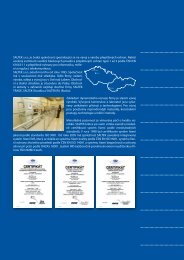
SALTEK, Limited Liability Company, is a Czech company specialized in the development and the<br />
production of surge protective devices (SPD). We offer a wide assortment of lightning current<br />
arresters and surge protections protecting electric and electronic equipment in low voltage<br />
supply mains, a wide range of surge protections for computers, measurement and control and<br />
telecommunication. All products conform to international standards.<br />
SALTEK was established in 1995. The company’s headquarters, Management, Production,<br />
Sales and Development are all based in Ústí nad Labem. Since its establishment, SALTEK has<br />
achieved very good results and high annual turnover growth and we soon became the Czech<br />
market leader. The principle of dynamic company expansion lies in our product development,<br />
using sophisticated materials, design processes, technologies and measuring methods. The<br />
development area and our laboratory are equipped with unique apparatuses and technologies.<br />
Exceptional attention is paid to care for product quality. The Quality Control System according<br />
to ISO 9000 standards was introduced and certified in 1998. In the following year, the company<br />
implemented the Safety Management System and the Environmental Management System. The<br />
company is audited by TÜV NORD Czech, s.r.o., a member of the TÜV NORD Gruppe, on a yearly<br />
basis.<br />
For a long time, SALTEK has maintained a dominant position on the Czech market of surge<br />
protections and also a firm position in Europe. Foreign trade activities are secured by our<br />
subsidiaries, SALTEK TRADE, SALTEK Slovakia and SALTEK RU.<br />
SALTEK organizes regular training for designers, investors and suppliers, where we present our<br />
products as well as new trends in the surge protection field. At such training, we introduce our<br />
partners and clients to our range of surge protections, with the proper method of their design,<br />
installation and use.<br />
The SALTEK Company represents itself at professional exhibitions in the Czech Republic and<br />
abroad. Traditionally, we take part in the most significant Czech trade fair, AMPER, and in the<br />
professional exhibitions ELOSYS and ELEKTROTECHNIKA Ostrava. Since 2000, SALTEK has<br />
exhibited at the international Light & Building Fair in Frankfurt upon Mohan and the Hannover<br />
Messe Fair in Hanover.
SALTEK<br />
Choose from our wide range of surge arresters:<br />
SPD type 1 – lightning current arresters<br />
SPD type 1 and 2 – combined B+C<br />
SPD type 2 – surge arresters<br />
Surge separating inductors<br />
SPD type 3 – surge arresters<br />
SPD type 3 – surge arresters with RFI filter<br />
SPD type 3 – sockets with surge arrester<br />
SPD type 3 – surge arresters to be installed in 19“ racks<br />
Surge arresters for measurement and control, electric security<br />
signalization (ESS), electric fire signalization (EFS), telecommunication<br />
Surge arresters for video circuits and coaxial lines<br />
Lightning current arresters for coaxial lines<br />
Special devices
Lightning and surge protection<br />
Lightning and surge protection<br />
1. Introduction – Legislative<br />
The use of modern sophisticated apparatuses,<br />
equipment, consumer electronics and<br />
control systems places high demands on<br />
their electromagnetic compatibility. Modern<br />
electronic control systems provided with circuits<br />
with a very high integration level are becoming<br />
more and more sensitive to electromagnetic<br />
disturbance and overvoltage. The installation of<br />
surge protections according to effective legal<br />
regulations will reduce the danger of their being<br />
damaged to a minimum.<br />
Conditions for safe operation and function of<br />
electrical equipment for the Czech Republic<br />
are specified in detail in Act 205/2002 and<br />
Ordinance 18/2003.<br />
Technical designs are defined by standards<br />
harmonised with EU standards:<br />
a) Protective bonding to the same potential<br />
including the conductor cross section for the<br />
main and additional bonding is defined by<br />
standards EN 50 310.<br />
b) Lightning protection is specified in the<br />
EN 62 305 collection of new standards,<br />
harmonised with European standards,<br />
whereas EN 62 305 – Section 1 deals with<br />
general principles.<br />
Lightning<br />
protection<br />
level<br />
LPL<br />
Maximum lightning parameter<br />
according to LPL<br />
First short<br />
discharge<br />
Discharge<br />
charge<br />
LPL I 200 kA 100 C<br />
LPL II 150 kA 75 C<br />
LPL III 100 kA 50 C<br />
LPL IV 100 kA 50 C<br />
EN 62 305 – Section 2 – deals with the risk<br />
assessment for buildings or engineering<br />
networks struck by downward lightning.<br />
EN 62 305 – Section 3 – deals with the proposal<br />
for external lightning protection (lightning<br />
conductor).<br />
telephone cable<br />
water pipeline<br />
gas pipeline<br />
main protective bonding bar<br />
Example of main and additional bonding<br />
Lightning protection zones<br />
The standard EN 62305-4 (EN 61312-3) defines<br />
lightning protection zones LPZ in view of the<br />
direct and indirect (electromagnetic pulse – LEMP)<br />
lightning effect:<br />
LPZ 0 A – free area (possibility of a direct<br />
lightning strike, non-attenuated LEMP)<br />
LPZ 0 B – lightning conductor receiver<br />
protection area (direct lightning strike<br />
protection, non-attenuated LEMP)<br />
LPZ 1 – inside a building (direct lightning strike<br />
is eliminated, attenuated LEMP – depending<br />
upon shielding)<br />
LPZ 2 – inside a room – e.g. a server room with<br />
a conductive floor, FeAl floors and wall lining<br />
(further attenuation of LEMP in connection with<br />
a higher shielding level)<br />
LPZ 3 – inside a metal box (e.g. 19“ RACK)<br />
base ground<br />
EN 62 305 – Section 4 – deals with protective<br />
measures resulting in the reduction of failures<br />
of electric and electronic systems inside the<br />
building (zone protection) (also in ČSN IEC 61<br />
312-3).<br />
c) Classification of protections is set forth in<br />
standard EN 61 643-11.<br />
Protections are classified into three basic<br />
categories:<br />
SPD type 1 – lightning current arresters<br />
SPD type 2 – surge protections<br />
SPD type 3 – surge protections<br />
lift<br />
flats<br />
appliances<br />
appliance<br />
d) Classification of low-voltage distributions<br />
into impulse resistance categories, including<br />
specification of the maximum allowed<br />
overvoltage is determined in standard<br />
EN 60 664-1<br />
Nominal impulse resistance voltage of equipment (acc. to EN 60 664-1)<br />
<br />
www.saltek.cz
Lightning and surge protection<br />
2. Connection of protections in TN, TT and IT systems<br />
SPD connection in TN-C system SPD connection in TN-S system SPD connection in TT system SPD connection in IT system<br />
SPD type 1 SPD type 2 SPD type 3<br />
Principle of connection of surge<br />
protections in TN systems<br />
3. Protection dimensioning and their location<br />
Only lightning current arresters are dimensioned (SPD type 1) according to standard EN 62 305. Surge protections SPD type 2 and SPD type 3 are not<br />
dimensioned.<br />
SPD type 1 dimensioning<br />
according to EN 62305<br />
SPD type 1 location: at the boundary of LPZ0 and LPZ1 zones<br />
Building risk category lightning arresters in total<br />
I. up to 200 kA 100 kA<br />
II. up to 150 kA 75 kA<br />
III. up to 100 kA 50 kA<br />
IV. up to 100 kA 50 kA<br />
Application of SALTEK protections SPD type 1<br />
according to EN 62305<br />
SPD type 1 location: at the boundary of LPZ0 and LPZ1 zones<br />
Building risk category lightning arresters in total<br />
I. up to 200 kA 100 kA<br />
The following protections meet the specified conditions:<br />
FLP-A50-1,5<br />
- large industrial plants<br />
- buildings of significant importance<br />
FLP-A35<br />
- technological plants<br />
- office buildings<br />
FLP-A35-0,9<br />
- small technological plants<br />
- office buildings<br />
(if SPD type 1 and 2 is located in one distributor)<br />
Application of SALTEK protections SPD type 2<br />
according to EN 62305<br />
SPD type 2 location: at the boundary of LPZ1 and LPZ2 zones<br />
The following protections meet the specified conditions:<br />
SLP-xxx<br />
- wiring systems of all types<br />
- system type (TN, IT, TT)<br />
- wiring method<br />
-nominal voltage<br />
Application of SALTEK protections SPD type 3<br />
according to EN 62305<br />
SPD type 3 location: at the boundary of LPZ2 and LPZ3 zones<br />
The following protections meet the specified conditions:<br />
DA-275<br />
(mounted on DIN rail)<br />
DA-275 …, CZ …<br />
xxx-OVERDRIVE<br />
- wiring systems of all types (if the device<br />
or a control system is in the distributor)<br />
- wiring systems of all types (sockets with surge<br />
protection are in the closest proximity to the<br />
equipment)<br />
- wiring systems of all types (adaptors for sockets<br />
with surge protection – flexible solution)<br />
Application of SALTEK protections SPD type 1<br />
according to EN 62305<br />
SPD type 1 location: at the boundary of LPZ0 and LPZ1 zones<br />
Building risk category lightning arresters in total<br />
II. up to 150 kA 75 kA<br />
The following protections meet the specified conditions:<br />
FLP-B+C GE<br />
- smaller office buildings<br />
- civic amenity buildings<br />
- residential houses<br />
www.saltek.cz
Lightning and surge protection<br />
4. Principles of positioning and wiring of surge protections and lightning current arresters<br />
Surge protections and lightning current arresters cannot be installed in the distributor at random. You must be aware of the fact that protection should be<br />
placed in closest proximity to the input feed cable in the distributor in order to minimize the inductive loop area, see fig. 1.<br />
Fig. 1 – Examples of protection positioning in the distributor.<br />
overhead, PEN (PE) down overhead, PEN (PE) up underground, PEN (PE) down underground, PEN (PE) up<br />
Another important condition for the wiring of protections is to minimize the impedance of interconnecting conductors. Since the fault current flowing<br />
through the protection has a frequency at which the current does not flow through the whole cross section but pushes towards the conductor surface<br />
(skin effect), it is necessary to use a stranded conductor or a strip conductor for the wiring of protections. Furthermore, the length of the interconnecting<br />
conductors must be as short as possible (the total length of interconnecting conductors must not exceed 0.5 m). The cross section of the interconnecting<br />
conductors should be as large as possible – maximum up to the cross section according to the terminal type.<br />
The cross section of interconnecting conductors is recommended to be larger by at least one sequence number than the PEN (PE) conductor diameter (e.g.<br />
if the PEN conductor diameter is 10 mm 2 , the cross section of the interconnecting conductor should be 16 mm 2 ).<br />
If protections are placed in a circuit fitted with residual current devices (RCD), the protection must be set before the RCD (not in the RCD circuit) to avoid<br />
spontaneous RCD availability due to surge protections or lightning current arresters.<br />
If the RC is placed before the protection, it is necessary to use the delayed RCD type, e.g. S-type or G-type.<br />
5. Example of protection application<br />
SAT-OVERDRIVE<br />
FX<br />
HX<br />
SX<br />
ZX<br />
HX<br />
SX<br />
DL-TLF (ASDL)<br />
FLP-B+C GE DA-275 DF6 CZ-275 A<br />
FLP-B+C GE/3+1<br />
DA-275 DF6<br />
<br />
www.saltek.cz
Lightning and surge protection<br />
Content<br />
FLP-A50-1,5 SPD type 1 – Lightning current arrester 6<br />
FLP-A35 SPD type 1 – Lightning current arrester 7<br />
FLP-A35-0,9 SPD type 1 – Lightning current arrester 8<br />
FLP-A100 N SPD type 1 – Lightning current arrester 9<br />
FLP-B+C GE SPD type 1 – Combined arrester type 1 and 2 10<br />
FLP-B+C GE S SPD type 1 – Combined arrester type 1 and 2 10<br />
FLP-B+C GE/3 SPD type 1 – Combined arrester type 1 and 2 11<br />
FLP-B+C GE/3 S SPD type 1 – Combined arrester type 1 and 2 11<br />
FLP-B+C GE/3+1 SPD type 1 – Combined arrester type 1 and 2 12<br />
FLP-B+C GE/3S+1 SPD type 1 – Combined arrester type 1 and 2 12<br />
FLP-NPE SPD type 1 – Lightning current arrester 13<br />
FLP-275 V SPD type 1 – Lightning current arrester 14<br />
FLP-275 VS SPD type 1 – Lightning current arrester 14<br />
FLP-275 V/0 Spare module 14<br />
FLP-275 V/3 SPD type 1 – Lightning current arrester 15<br />
FLP-275 V/3 S SPD type 1 – Lightning current arrester 15<br />
FLP-275 V/4 SPD type 1 – Lightning current arrester 16<br />
FLP-275 V/4 S SPD type 1 – Lightning current arrester 16<br />
SLP-075 V SPD type 2 – Surge arrester 17<br />
SLP-130 V SPD type 2 – Surge arrester 17<br />
SLP-275 V SPD type 2 – Surge arrester 17<br />
SLP-385 V SPD type 2 – Surge arrester 17<br />
SLP-440 V SPD type 2 – Surge arrester 17<br />
SLP-550 V SPD type 2 – Surge arrester 17<br />
SLP-075 VS SPD type 2 – Surge arrester 18<br />
SLP-130 VS SPD type 2 – Surge arrester 18<br />
SLP-275 VS SPD type 2 – Surge arrester 18<br />
SLP-385 VS SPD type 2 – Surge arrester 18<br />
SLP-440 VS SPD type 2 – Surge arrester 18<br />
SLP-550 VS SPD type 2 – Surge arrester 18<br />
SLP-275 V/3 SPD type 2 – Surge arrester 19<br />
SLP-275 V/3S SPD type 2 – Surge arrester 19<br />
SLP-275 V/4 SPD type 2 – Surge arrester 20<br />
SLP-275 V/4S SPD type 2 – Surge arrester 20<br />
SLP-275 V/1+1 SPD type 2 – Surge arrester 21<br />
SLP-275 V/1S+1 SPD type 2 – Surge arrester 21<br />
SLP-275 V/3+1 SPD type 2 – Surge arrester 22<br />
SLP-275 V/3S+1 SPD type 2 – Surge arrester 22<br />
SLP-075 V/0 Spare module 23<br />
SLP-130 V/0 Spare module 23<br />
SLP-275 V/0 Spare module 23<br />
SLP-385 V/0 Spare module 23<br />
SLP-440 V/0 Spare module 23<br />
SLP-550 V/0 Spare module 23<br />
SLP-NPE V/0 Spare module 23<br />
SLP-330 GE V SPD type 2 - Surge arrester with suppressed leakage current 24<br />
SLP-330 GE VS SPD type 2 - Surge arrester with suppressed leakage current 24<br />
SLP-330 GE V/1+1 SPD type 2 - Surge arrester with suppressed leakage current 25<br />
SLP-330 GE V/1S+1 SPD type 2 - Surge arrester with suppressed leakage current 25<br />
SLP-330 GE V/3+1 SPD type 2 - Surge arrester with suppressed leakage current 26<br />
SLP-330 GE V/3S+1 SPD type 2 - Surge arrester with suppressed leakage current 26<br />
SLP-075 VB SPD type 2 – Surge arrester 27<br />
SLP-130 VB SPD type 2 – Surge arrester 27<br />
SLP-275 VB SPD type 2 – Surge arrester 27<br />
SLP-075 VBS SPD type 2 – Surge arrester 28<br />
SLP-130 VBS SPD type 2 – Surge arrester 28<br />
SLP-275 VBS SPD type 2 – Surge arrester 28<br />
SLP-075 VB/0 Spare module 29<br />
SLP-130 VB/0 Spare module 29<br />
SLP-275 VB/0 Spare module 29<br />
SLP-330 GE V/0 Spare module 29<br />
RTO-16 Surge separating inductor 30<br />
RTO-35 Surge separating inductor 30<br />
RTO-63 Surge separating inductor 30<br />
DA-275 V/1+1 SPD type 3 – Surge arrester 31<br />
DA-275 V/1S+1 SPD type 3 – Surge arrester 31<br />
DA-275 V/3+1 SPD type 3 – Surge arrester 32<br />
DA-275 V/3S+1 SPD type 3 – Surge arrester 32<br />
DA-275 V/0 Spare module 33<br />
DA-NPE V/0 Spare module 33<br />
DA-130 DJ SPD type 3 – Surge arrester 34<br />
DA-275 DJ SPD type 3 – Surge arrester 34<br />
DA-275 DF 2 SPD type 3 – Surge arrester with RFI filter 35<br />
DA-275 DF 6 SPD type 3 – Surge arrester with RFI filter 35<br />
DA-275 DF 2 S SPD type 3 – Surge arrester with RFI filter 36<br />
DA-275 DF 6 S SPD type 3 – Surge arrester with RFI filter 36<br />
DA-275 DF 10 SPD type 3 – Surge arrester with RFI filter 37<br />
DA-275 DF 16 SPD type 3 – Surge arrester with RFI filter 37<br />
DA-275 DF 10 S SPD type 3 – Surge arrester with RFI filter 38<br />
DA-275 DF 16 S SPD type 3 – Surge arrester with RFI filter 38<br />
DA-275 DFI 1 SPD type 3 – Surge arrester with RFI filter 39<br />
DA-275 DFI 6 SPD type 3 – Surge arrester with RFI filter 40<br />
DA-275 DFI 10 SPD type 3 – Surge arrester with RFI filter 41<br />
DA-275 DFI 16 SPD type 3 – Surge arrester with RFI filter 41<br />
DA-400 DF 16 SPD type 3 – Surge arrester with RFI filter 42<br />
DA-400 DF 16 S SPD type 3 – Surge arrester with RFI filter 42<br />
DA-275 BFG SPD type 3 – Surge arrester with RFI filter 43<br />
CZ-275 A SPD type 3 – Surge arrester 44<br />
CZ-275 S SPD type 3 – Surge arrester 45<br />
NM-275 A SPD type 3 – Surge arrester 46<br />
NM-275 O SPD type 3 – Surge arrester 47<br />
DA-275 PP1 SPD type 3 – Socket with surge protection 48<br />
PA-OVERDRIVE X16 SPD type 3 – Surge arrester 49<br />
PA-OVERDRIVE F6 SPD type 3 – Surge arrester with RFI filter 49<br />
PA-OVERDRIVE F16 SPD type 3 – Surge arrester with RFI filter 49<br />
FAX-OVERDRIVE X16 SPD type 3 – Surge arrester 50<br />
FAX-OVERDRIVE F6 SPD type 3 – Surge arrester with RFI filter 50<br />
FAX-OVERDRIVE F16 SPD type 3 – Surge arrester with RFI filter 50<br />
ISDN-OVERDRIVE X16 SPD type 3 – Surge arrester 51<br />
TV-OVERDRIVE X16 SPD type 3 – Surge arrester 52<br />
TV-OVERDRIVE F6 SPD type 3 – Surge arrester with RFI filter 52<br />
SAT-OVERDRIVE X16 SPD type 3 – Surge arrester 53<br />
SAT-OVERDRIVE F6 SPD type 3 – Surge arrester with RFI filter 53<br />
NET-OVERDRIVE X16 SPD type 3 – Surge arrester 54<br />
NET-OVERDRIVE F6 SPD type 3 – Surge arrester with RFI filter 54<br />
P-PROTECTOR F8 SPD type 3 – Surge arrester with RFI filter 55<br />
RACK-PROTECTOR X8 SPD type 3 – Surge arrester into 19“ racks 56<br />
RACK-PROTECTOR F8 SPD type 3 – Surge arrester with RFI filter into 19“ racks 56<br />
RACK-PROTECTOR VF7 SPD type 3 – Surge arrester with RFI filter and a switch<br />
56<br />
into 19“ racks<br />
RACK-PROTECTOR UPS X6 SPD type 3 – Surge arrester into 19“ racks 57<br />
RACK-PROTECTOR UPS F6 SPD type 3 – Surge arrester with RFI filter into 19“ racks 57<br />
RACK-PROTECTOR<br />
EURO X12<br />
SPD type 3 – Surge arrester into 19“ racks 58<br />
www.saltek.cz
Lightning Current Arresters<br />
FLP-A50-1,5<br />
SPD type 1 – lightning current arrester<br />
Encapsulated high-performance spark gap<br />
To be installed in low-voltage distributions at the boundary of<br />
LPZ 0 A and LPZ 1 zones to prevent overvoltage effects induced<br />
during direct or indirect lightning strikes in the most demanding<br />
applications in the heavy and chemicals industry, power stations,<br />
etc. It is perfectly coordinated with SPD type 2 – SLP-385 (V) even<br />
without the use of separating inductors.<br />
Dimension drawing<br />
Basic circuit diagram<br />
Technical data<br />
FLP-A50-1,5<br />
Nominal voltage U n 400 V AC<br />
Maximum operating voltage U c 440 V AC<br />
Nominal discharge current (8/20 μs) I n 50 kA<br />
Lightning impulse current (10/350 μs) I imp 50 kA<br />
Voltage protection level U p 1,5 kV<br />
Response time t a 100 ns<br />
Ability to independently switch off the following current I fi 50 kA<br />
Maximum overcurrent protection<br />
250 A gL/gG<br />
Degree of protection IP 20<br />
Range of operating temperatures - 40 °C … + 80 °C<br />
Mounting on<br />
DIN rail 35 mm<br />
Cross-section of connected conductors<br />
Solid min/max ISO: 10/50 mm 2 ; AWG: 8/1<br />
Stranded min/max ISO: 10/35 mm 2 ; AWG: 8/2<br />
Stripping length of the supply conductor<br />
14 mm<br />
Tightening torque<br />
max. 4 Nm<br />
Fault indication<br />
no<br />
Remote indication<br />
no<br />
Meets the requirements of standard EN 61 643-11<br />
Ordering number 8595090529194<br />
<br />
www.saltek.cz
Lightning Current Arresters<br />
FLP-A35<br />
SPD type 1 – lightning current arrester<br />
Encapsulated high-performance spark gap<br />
To be installed in low-voltage distributions at the boundary of<br />
LPZ 0 A and LPZ 1 zones to prevent overvoltage effects induced<br />
during direct or indirect lightning strikes. Installation of the<br />
separating inductor or observance of accurate distance secures<br />
coordination with SPD type 2 (SLP-275 V).<br />
Dimension drawing<br />
Basic circuit diagram<br />
Technical data<br />
FLP-A35<br />
Nominal voltage U n 230 V AC<br />
Maximum operating voltage U c 440 V AC<br />
Nominal discharge current (8/20 μs) I n 35 kA<br />
Lightning impulse current (10/350 μs) I imp 35 kA<br />
Voltage protection level U p 4 kV<br />
Response time t a 100 ns<br />
Ability to independently switch off the following current I fi 3 kA / 260 V AC<br />
Maximum overcurrent protection<br />
125 A gL/gG<br />
Degree of protection IP 20<br />
Range of operating temperatures - 40 °C … + 80 °C<br />
Mounting on<br />
DIN rail 35 mm<br />
Cross-section of connected conductors<br />
Solid min/max ISO: 10/50 mm 2 ; AWG: 8/1<br />
Stranded min/max ISO: 10/35 mm 2 ; AWG: 8/2<br />
Stripping length of the supply conductor<br />
14 mm<br />
Tightening torque<br />
max. 4,5 Nm<br />
Fault indication<br />
no<br />
Remote indication<br />
no<br />
Meets the requirements of standard EN 61 643-11<br />
Ordering number 8595090518822<br />
www.saltek.cz
Lightning Current Arresters<br />
FLP-A35-0,9<br />
SPD type 1 – lightning current arrester<br />
Encapsulated high-performance spark gap<br />
To be installed in low-voltage distributions at the boundary of<br />
LPZ 0 A and LPZ 1 zones to prevent overvoltage effects induced<br />
during direct or indirect lightning strikes. It is installed in the<br />
distributor directly before SPD type 2 (SLP-275 V) without the<br />
need for the use of a separating inductor.<br />
Dimension drawing<br />
Basic circuit diagram<br />
Technical data<br />
FLP-A35-0,9<br />
Nominal voltage U n 230 V AC<br />
Maximum operating voltage U c 260 V AC<br />
Nominal discharge current (8/20 μs) I n 35 kA<br />
Lightning impulse current (10/350 μs) I imp 35 kA<br />
Voltage protection level U p 0,9 kV<br />
Response time t a
Lightning Current Arresters<br />
FLP-A100 N<br />
SPD type 1 – lightning current arrester<br />
Spark gap for N-PE<br />
To be installed in low-voltage distributions at the boundary of<br />
LPZ 0 A and LPZ 1 zones to prevent overvoltage effects induced<br />
during direct or indirect lightning strikes for the connection of<br />
SPD type 1 in the mode 3+1 and 1+1.<br />
Dimension drawing<br />
Basic circuit diagram<br />
Technical data<br />
FLP-A100 N<br />
Maximum operating voltage U c 260 V AC<br />
Nominal discharge current (8/20 μs) I n 50 kA<br />
Lightning impulse current (10/350 μs) I imp 100 kA<br />
Voltage protection level U p 4 kV<br />
Response time t a 100 ns<br />
Ability to independently switch off the following current I fi 350 A/260 V AC<br />
Degree of protection IP 20<br />
Range of operating temperatures - 40 °C … + 80 °C<br />
Mounting on<br />
DIN rail 35 mm<br />
Cross-section of connected conductors<br />
Solid min/max ISO: 10/50 mm 2 ; AWG: 8/1<br />
Stranded min/max ISO: 10/35 mm 2 ; AWG: 8/2<br />
Stripping length of the supply conductor<br />
14 mm<br />
Tightening torque<br />
max. 4 Nm<br />
Fault indication<br />
no<br />
Remote indication<br />
no<br />
Meets the requirements of standard EN 61 643-11<br />
Ordering number 8595090521860<br />
www.saltek.cz
Lightning Current Arresters<br />
FLP-B+C GE<br />
FLP-B+C GE S<br />
SPD type 1 – combined arrester type 1 and 2<br />
Visual fault signalling<br />
Highly efficient varistor lightning current arrester to be installed<br />
in low-voltage distributions at the boundary of LPZ 0 A –LPZ<br />
1 zones and higher, to prevent overvoltage effects induced<br />
during direct or indirect lightning strikes. It is particularly<br />
suitable for residential houses and small buildings with<br />
a low-voltage cable terminal or for secondary switchboards in<br />
large building. Optional remote status signalling (S).<br />
Dimension drawing<br />
Basic circuit diagram<br />
connection of signalization<br />
terminal<br />
Technical data<br />
FLP-B+C GE<br />
Nominal voltage U n 230 V AC<br />
Maximum operating voltage U c 330 V AC<br />
Nominal discharge current (8/20 μs) I n 30 kA<br />
Lightning impulse current (10/350 μs) I imp 20 kA<br />
Voltage protection level (t < 2 μs) U p 1,5 kV<br />
Voltage protection level (t > 2 μs) U p 0,8 kV<br />
Response time t a 100 ns<br />
Ability to independently switch off the following current I fi no following current<br />
Short-circuit proof at maximum overcurrent protection<br />
25 kA rms<br />
Maximum overcurrent protection<br />
250 A gL/gG<br />
Degree of protection IP 20<br />
Range of operating temperatures - 40 °C … + 80 °C<br />
Mounting on<br />
DIN rail 35 mm<br />
Cross-section of connected conductors<br />
Solid min/max ISO: 10/50 mm 2 ; AWG: 8/1<br />
Stranded min/max ISO: 10/35 mm 2 ; AWG: 8/2<br />
Stripping length of the supply conductor<br />
14 mm<br />
Tightening torque<br />
max. 4 Nm<br />
Fault indication<br />
red indication field<br />
Remote indication – S design<br />
potential-free change-over contact<br />
Remote indication contacts<br />
250 V / 0,5 A AC, 250 V / 0,1 A DC<br />
Cross-section of remote indication conductors max. 1,5 mm 2<br />
Meets the requirements of standard EN 61 643-11<br />
Ordering number<br />
FLP-B+C GE 8595090529545<br />
FLP-B+C GE S 8595090529576<br />
10 www.saltek.cz
Lightning Current Arresters<br />
FLP-B+C GE/3<br />
FLP-B+C GE/3 S<br />
SPD type 1 – combined arrester type 1 and 2<br />
Visual fault signalling<br />
Highly efficient, 3-pole varistor lightning current arrester to be<br />
installed in low-voltage distributions at the boundary of<br />
LPZ 0 A –LPZ 1 zones and higher to prevent overvoltage<br />
effects induced during direct or indirect lightning strikes. It is<br />
particularly suitable for residential houses and small buildings<br />
with a low-voltage cable terminal or for secondary switchboards<br />
in large buildings. Optional remote status signalling (S).<br />
Dimension drawing<br />
Basic circuit diagram<br />
Technical data<br />
FLP-B+C GE/3<br />
Nominal voltage U n 230 V AC<br />
Maximum operating voltage U c 330 V AC<br />
Nominal discharge current (8/20 μs)/pole I n 30 kA<br />
Lightning impulse current (10/350 μs)/pole I imp 20 kA<br />
Voltage protection level (t < 2 μs) U p 1,5 kV<br />
Voltage protection level (t > 2 μs) U p 0,8 kV<br />
Response time t a 100 ns<br />
Ability to independently switch off the following current I fi no following current<br />
Short-circuit proof at maximum overcurrent protection<br />
25 kA rms<br />
Maximum overcurrent protection<br />
250 A gL/gG<br />
Degree of protection IP 20<br />
Range of operating temperatures - 40 °C … + 80 °C<br />
Mounting on<br />
DIN rail 35 mm<br />
Cross-section of connected conductors<br />
Solid min/max ISO: 10/50 mm 2 ; AWG: 8/1<br />
Stranded min/max ISO: 10/35 mm 2 ; AWG: 8/2<br />
Stripping length of the supply conductor<br />
14 mm<br />
Tightening torque<br />
max. 4 Nm<br />
Fault indication<br />
red indication field<br />
Remote indication – S design<br />
potential-free change-over contact<br />
Remote indication contacts<br />
250 V / 0,5 A AC, 250 V / 0,1 A DC<br />
Cross-section of remote indication conductors max. 1,5 mm 2<br />
Meets the requirements of standard EN 61 643-11<br />
Ordering number<br />
FLP-B+C GE/3 8595090530299<br />
FLP-B+C GE/3 S 8595090529262<br />
connection of signalization terminal<br />
www.saltek.cz<br />
11
Lightning Current Arresters<br />
FLP-B+C GE/3+1<br />
FLP-B+C GE/3S+1<br />
SPD type 1 – combined arrester type 1 and 2<br />
Visual fault signalling<br />
The combination of a highly efficient, 3-pole varistor lightning<br />
current arrester and an encapsulated high-performance spark<br />
gap connected in the mode 3+1 for installation in low-voltage<br />
distributions at the boundary of LPZ 0 A –LPZ 1 zones and higher<br />
to prevent overvoltage effects induced during direct or indirect<br />
lightning strikes. It is particularly suitable for residential houses<br />
and small buildings with a low-voltage cable terminal or to<br />
secondary switchboards in large buildings. Optional remote<br />
status signalling (S).<br />
Dimension drawing<br />
Basic circuit diagram<br />
Technical data<br />
L-N<br />
N-PE<br />
Nominal voltage U n 230 V AC —<br />
Maximum operating voltage U c 330 V AC 300 V AC<br />
Nominal discharge current (8/20 μs)/pole I n 30 kA 60 kA<br />
Lightning impulse current (10/350 μs)/pole I imp 20 kA 80 kA<br />
Voltage protection level (t < 2 μs) U p 1,5 kV —<br />
Voltage protection level (t > 2 μs) U p 0,8 kV —<br />
Voltage protection level U p — 1,5 kV<br />
Response time t a 100 ns 100 ns<br />
Ability to independently switch off the following current I fi no following current 100 A / 260 V AC<br />
Short-circuit proof at maximum overcurrent protection 25 kA rms —<br />
Maximum overcurrent protection 250 A gL/gG —<br />
Degree of protection IP 20 IP 20<br />
Range of operating temperatures - 40 °C … + 80 °C - 40 °C … + 80 °C<br />
Mounting on DIN rail 35 mm DIN rail 35 mm<br />
Cross-section of connected conductors<br />
Solid min/max ISO: 10/50 mm 2 ; AWG: 8/1 ISO: 10/50 mm 2 ; AWG: 8/1<br />
Stranded min/max ISO: 10/35 mm 2 ; AWG: 8/2 ISO: 10/35 mm 2 ; AWG: 8/2<br />
Stripping length of the supply conductor 14 mm 14 mm<br />
Tightening torque max. 4 Nm max. 4 Nm<br />
Fault indication red indication field no<br />
Remote indication – S design potential-free change-over contact —<br />
Remote indication contacts 250 V / 0,5 A AC, 250 V / 0,1 A DC —<br />
Cross-section of remote indication conductors max. 1,5 mm 2 —<br />
Meets the requirements of standard EN 61 643-11 EN 61 643-11<br />
Ordering number<br />
FLP-B+C GE/3+1 8595090530282<br />
FLP-B+C GE/3S+1 8595090530367<br />
connection of signalization terminal<br />
12 www.saltek.cz
Lightning Current Arresters<br />
FLP-NPE<br />
SPD type 1 – lightning current arrester<br />
N-PE module<br />
To be installed in low-voltage distributions at the boundary of<br />
LPZ 0 A –LPZ 1 zones and higher to prevent overvoltage effects induced<br />
during direct or indirect lightning strikes for the connection of<br />
SPD type 1 in the mode 3+1 and 1+1.<br />
Dimension drawing<br />
Basic circuit diagram<br />
Technical data<br />
FLP-NPE<br />
Maximum operating voltage U c 300 V AC<br />
Nominal discharge current (8/20 μs) I n 60 kA<br />
Lightning impulse current (10/350 μs) I imp 80 kA<br />
Voltage protection level U p 1,5 kV<br />
Response time t a 100 ns<br />
Ability to independently switch off the following current I fi 100 A / 260 V AC<br />
Short-circuit proof at maximum overcurrent protection —<br />
Maximum overcurrent protection —<br />
Degree of protection IP 20<br />
Range of operating temperatures - 40 °C … + 80 °C<br />
Mounting on<br />
DIN rail 35 mm<br />
Cross-section of connected conductors<br />
Solid min/max ISO: 10/50 mm 2 ; AWG: 8/1<br />
Stranded min/max ISO: 10/35 mm 2 ; AWG: 8/2<br />
Stripping length of the supply conductor<br />
14 mm<br />
Tightening torque<br />
max. 4 Nm<br />
Fault indication<br />
no<br />
Meets the requirements of standard EN 61 643-11<br />
Ordering number 8595090530022<br />
www.saltek.cz<br />
13
Lightning Current Arresters<br />
FLP-275 V<br />
FLP-275 VS<br />
SPD type 1 – lightning current arrester<br />
Replaceable varistor module, visual fault signalling<br />
Varistor lightning current arrester to be installed in low-voltage<br />
distributions at the boundary of LPZ 0 B –LPZ 1 zones and higher<br />
to prevent overvoltage effects induced during a lightning strike<br />
and to prevent switching overvoltage.<br />
Optional remote status signalling (S).<br />
Dimension drawing<br />
Basic circuit diagram<br />
connection of signalization<br />
terminal<br />
Technical data<br />
FLP-275 V<br />
Nominal voltage U n 230 V AC<br />
Maximum operating voltage U c 275 V AC / 350 V DC<br />
Nominal discharge current (8/20 μs) I n 30 kA<br />
Lightning impulse current (10/350 μs) I imp 7 kA<br />
Voltage protection level U p 1,2 kV<br />
Response time t a 25 ns<br />
Short-circuit proof at maximum overcurrent protection<br />
35 kA rms<br />
Maximum overcurrent protection<br />
125 A gL/gG<br />
Degree of protection IP 20<br />
Range of operating temperatures - 40 °C … + 80 °C<br />
Mounting on<br />
DIN rail 35 mm<br />
Cross-section of connected conductors<br />
Solid min/max ISO: 10/50 mm 2 ; AWG: 8/1<br />
Stranded min/max ISO: 10/35 mm 2 ; AWG: 8/2<br />
Stripping length of the supply conductor<br />
14 mm<br />
Tightening torque<br />
max. 4 Nm<br />
Fault indication<br />
red indication field<br />
Remote indication – S design<br />
potential-free change-over contact<br />
Remote indication contacts<br />
250 V / 0,5 A AC, 250 V / 0,1 A DC<br />
Cross-section of remote indication conductors max. 1,5 mm 2<br />
Meets the requirements of standard EN 61 643-11<br />
Ordering number<br />
FLP-275 V 8595090516200<br />
FLP-275 VS 8595090516217<br />
Accessories<br />
FLP-275 V/0<br />
Spare module<br />
Ordering number: 8595090523697<br />
14 www.saltek.cz
Lightning Current Arresters<br />
FLP-275 V/3<br />
FLP-275 V/3 S<br />
SPD type 1 – lightning current arrester<br />
Replaceable varistor module, visual fault signalling<br />
3-pole varistor lightning current arrester to be installed in<br />
low-voltage distributions at the boundary of LPZ 0 B –LPZ 1<br />
zones and higher to prevent overvoltage effects induced during<br />
a lightning strike and to prevent switching overvoltage.<br />
Optional remote status signalling (S).<br />
Dimension drawing<br />
Basic circuit diagram<br />
connection of<br />
signalization terminal<br />
Technical data<br />
FLP-275 V/3<br />
Nominal voltage U n 230 V AC<br />
Maximum operating voltage U c 275 V AC / 350 V DC<br />
Nominal discharge current (8/20 μs)/pole I n 30 kA<br />
Lightning impulse current (10/350 μs)/pole I imp 7 kA<br />
Voltage protection level U p 1,2 kV<br />
Response time t a 25 ns<br />
Short-circuit proof at maximum overcurrent protection<br />
35 kA rms<br />
Maximum overcurrent protection<br />
125 A gL/gG<br />
Degree of protection IP 20<br />
Range of operating temperatures - 40 °C … + 80 °C<br />
Mounting on<br />
DIN rail 35 mm<br />
Cross-section of connected conductors<br />
Solid min/max ISO: 10/50 mm 2 ; AWG: 8/1<br />
Stranded min/max ISO: 10/35 mm 2 ; AWG: 8/2<br />
Stripping length of the supply conductor<br />
14 mm<br />
Tightening torque<br />
max. 4 Nm<br />
Fault indication<br />
red indication field<br />
Remote indication – S design<br />
potential-free change-over contact<br />
Remote indication contacts<br />
250 V / 0,5 A AC, 250 V / 0,1 A DC<br />
Cross-section of remote indication conductors max. 1,5 mm 2<br />
Meets the requirements of standard EN 61 643-11<br />
Ordering number<br />
FLP-275 V/3 8595090517757<br />
FLP-275 V/3 S 8595090517771<br />
www.saltek.cz<br />
15
Lightning Current Arresters<br />
FLP-275 V/4<br />
FLP-275 V/4 S<br />
SPD type 1 – lightning current arrester<br />
Replaceable varistor module, visual fault signalling<br />
4-pole varistor lightning current arrester to be installed in<br />
low-voltage distributions at the boundary of LPZ 0 B –LPZ 1<br />
zones and higher to prevent overvoltage effects induced<br />
during a lightning strike and to prevent switching overvoltage.<br />
Optional remote status signalling (S).<br />
Dimension drawing<br />
Basic circuit diagram<br />
connection of<br />
signalization terminal<br />
Technical data<br />
FLP-275 V/4<br />
Nominal voltage U n 230 V AC<br />
Maximum operating voltage U c 275 V AC / 350 V DC<br />
Nominal discharge current (8/20 μs)/pole I n 30 kA<br />
Lightning impulse current (10/350 μs)/pole I imp 7 kA<br />
Voltage protection level U p 1,2 kV<br />
Response time t a 25 ns<br />
Short-circuit proof at maximum overcurrent protection<br />
35 kA rms<br />
Maximum overcurrent protection<br />
125 A gL/gG<br />
Degree of protection IP 20<br />
Range of operating temperatures - 40 °C … + 80 °C<br />
Mounting on<br />
DIN rail 35 mm<br />
Cross-section of connected conductors<br />
Solid min/max ISO: 10/50 mm 2 ; AWG: 8/1<br />
Stranded min/max ISO: 10/35 mm 2 ; AWG: 8/2<br />
Stripping length of the supply conductor<br />
14 mm<br />
Tightening torque<br />
max. 4 Nm<br />
Fault indication<br />
red indication field<br />
Remote indication – S design<br />
potential-free change-over contact<br />
Remote indication contacts<br />
250 V / 0,5 A AC, 250 V / 0,1 A DC<br />
Cross-section of remote indication conductors max. 1,5 mm 2<br />
Meets the requirements of standard EN 61 643-11<br />
Ordering number<br />
FLP-275 V/4 8595090517788<br />
FLP-275 V/4 S 8595090517795<br />
16 www.saltek.cz
Surge Arresters<br />
SLP-075 V<br />
SLP-130 V<br />
SLP-275 V<br />
SLP-385 V<br />
SLP-440 V<br />
SLP-550 V<br />
SPD type 2 – surge arrester<br />
Replaceable varistor module,<br />
visual fault signalling<br />
Varistor surge protection to be<br />
installed in low-voltage distributions<br />
at the boundary of LPZ 1 and LPZ 2<br />
zones to protect the distributions and<br />
equipment against overvoltage effects<br />
induced during a lightning strike and<br />
to prevent switching overvoltage.<br />
Dimension drawing<br />
Basic circuit diagram<br />
Technical data<br />
SLP-075 V SLP-130 V SLP-275 V SLP-385 V SLP-440 V SLP-550 V<br />
Nominal voltage U n 60 V AC 110 V AC 230 V AC — 400 V AC 500 V AC<br />
Maximum operating voltage U c 75 V AC / 100 V DC 130 V AC / 170 V DC 275 V AC / 350 V DC 385 V AC / 500 V DC 440 V AC / 585 V DC 550 V AC / 745 V DC<br />
Nominal discharge current (8/20 μs) I n 10 kA 15 kA 20 kA 20 kA 20 kA 15 kA<br />
Maximum discharge current (8/20 μs) I max 40 kA 40 kA 40 kA 40 kA 40 kA 40 kA<br />
Voltage protection level @ I = 5 kA (8/20 μs) U p 0,3 kV 0,45 kV 0,9 kV 1,3 kV 1,5 kV 1,8 kV<br />
Voltage protection level U p 0,4 kV 0,6 kV 1,2 kV 1,8 kV 1,9 kV 2,2 kV<br />
Response time t a 25 ns 25 ns 25 ns 25 ns 25 ns 25 ns<br />
Short-circuit proof at maximum overcurrent protection 35 kA rms 35 kA rms 35 kA rms 35 kA rms 35 kA rms 35 kA rms<br />
Maximum overcurrent protection 125 A gL/gG 125 A gL/gG 125 A gL/gG 125 A gL/gG 125 A gL/gG 125 A gL/gG<br />
Degree of protection IP 20<br />
Range of operating temperatures - 40 °C … + 80 °C<br />
Mounting on<br />
DIN rail 35 mm<br />
Cross-section of connected conductors<br />
Solid min/max ISO: 10/50 mm 2 ; AWG: 8/1<br />
Stranded min/max ISO: 10/35 mm 2 ; AWG: 8/2<br />
Stripping length of the supply conductor<br />
14 mm<br />
Tightening torque<br />
max. 4 Nm<br />
Fault indication<br />
red indication field<br />
Meets the requirements of standard EN 61 643-11<br />
Ordering number 8595090518150 8595090518167 8595090516170 8595090519553 8595090518174 8595090517184<br />
www.saltek.cz<br />
17
Surge Arresters<br />
SLP-075 VS<br />
SLP-130 VS<br />
SLP-275 VS<br />
SLP-385 VS<br />
SLP-440 VS<br />
SLP-550 VS<br />
SPD type 2 – surge arrester<br />
Replaceable varistor module,<br />
visual fault signalling<br />
Varistor surge protection to be<br />
installed in low-voltage distributions<br />
at the boundary of LPZ 1 and LPZ 2<br />
zones to protect the distributions and<br />
equipment against overvoltage effects<br />
induced during a lightning strike and<br />
to prevent switching overvoltage.<br />
Remote status signalling (S).<br />
Dimension drawing<br />
Basic circuit diagram<br />
Technical data<br />
SLP-075 VS SLP-130 VS SLP-275 VS SLP-385 VS SLP-440 VS SLP-550 VS<br />
Nominal voltage U n 60 V AC 110 V AC 230 V AC — 400 V AC 500 V AC<br />
Maximum operating voltage U c 75 V AC / 100 V DC 130 V AC / 170 V DC 275 V AC / 350 V DC 385 V AC / 500 V DC 440 V AC / 585 V DC 550 V AC / 745 V DC<br />
Nominal discharge current (8/20 μs) I n 10 kA 15 kA 20 kA 20 kA 20 kA 15 kA<br />
Maximum discharge current (8/20 μs) I max 40 kA 40 kA 40 kA 40 kA 40 kA 40 kA<br />
Voltage protection level @ I = 5 kA (8/20 μs) U p 0,3 kV 0,45 kV 0,9 kV 1,3 kV 1,5 kV 1,8 kV<br />
Voltage protection level U p 0,4 kV 0,6 kV 1,2 kV 1,8 kV 1,9 kV 2,2 kV<br />
Response time t a 25 ns 25 ns 25 ns 25 ns 25 ns 25 ns<br />
Short-circuit proof at maximum overcurrent protection 35 kA rms 35 kA rms 35 kA rms 35 kA rms 35 kA rms 35 kA rms<br />
Maximum overcurrent protection 125 A gL/gG 125 A gL/gG 125 A gL/gG 125 A gL/gG 125 A gL/gG 125 A gL/gG<br />
Degree of protection IP 20<br />
Range of operating temperatures - 40 °C … + 80 °C<br />
Mounting on<br />
DIN rail 35 mm<br />
Cross-section of connected conductors<br />
Solid min/max ISO: 10/50 mm 2 ; AWG: 8/1<br />
Stranded min/max ISO: 10/35 mm 2 ; AWG: 8/2<br />
Stripping length of the supply conductor<br />
14 mm<br />
Tightening torque<br />
max. 4 Nm<br />
Fault indication<br />
red indication field<br />
Remote indication<br />
potential-free change-over contact<br />
Remote indication contacts<br />
250 V / 0,5 A AC, 250 V / 0,1 A DC<br />
Cross-section of remote indication conductors max. 1,5 mm 2<br />
Meets the requirements of standard EN 61 643-11<br />
Ordering number 8595090518235 8595090518242 8595090516187 8595090527718 8595090518259 8595090518266<br />
18 www.saltek.cz
Surge Arresters<br />
SLP-275 V/3<br />
SLP-275 V/3S<br />
SPD type 2 – surge arrester<br />
Replaceable varistor module, visual fault signalling<br />
3-pole varistor surge protection to be installed in low-voltage<br />
distributions at the boundary of LPZ 1 and LPZ 2 zones to<br />
protect the distributions and equipment against overvoltage<br />
effects induced during a lightning strike and to prevent<br />
switching overvoltage. Optional remote status signalling (S).<br />
Dimension drawing<br />
Basic circuit diagram<br />
connection of<br />
signalization terminal<br />
Technical data<br />
SLP-275 V/3<br />
Nominal voltage U n 230 V AC<br />
Maximum operating voltage U c 275 V AC / 350 V DC<br />
Nominal discharge current (8/20 μs)/pole I n 20 kA<br />
Maximum discharge current (8/20 μs)/pole I max 40 kA<br />
Voltage protection level @ I = 5 kA (8/20 μs) U p 0,9 kV<br />
Voltage protection level U p 1,2 kV<br />
Response time t a 25 ns<br />
Short-circuit proof at maximum overcurrent protection<br />
35 kA rms<br />
Maximum overcurrent protection<br />
125 A gL/gG<br />
Degree of protection IP 20<br />
Range of operating temperatures - 40 °C … + 80 °C<br />
Mounting on<br />
DIN rail 35 mm<br />
Cross-section of connected conductors<br />
Solid min/max ISO: 10/50 mm 2 ; AWG: 8/1<br />
Stranded min/max ISO: 10/35 mm 2 ; AWG: 8/2<br />
Stripping length of the supply conductor<br />
14 mm<br />
Tightening torque<br />
max. 4 Nm<br />
Fault indication<br />
red indication field<br />
Remote indication – S design<br />
potential-free change-over contact<br />
Remote indication contacts<br />
250 V / 0,5 A AC, 250 V / 0,1 A DC<br />
Cross-section of remote indication conductors max. 1,5 mm 2<br />
Meets the requirements of standard EN 61 643-11<br />
Ordering number<br />
SLP-275 V/3 8595090517603<br />
SLP-275 V/3S 8595090517610<br />
www.saltek.cz<br />
19
Surge Arresters<br />
SLP-275 V/4<br />
SLP-275 V/4S<br />
SPD type 2 – surge arrester<br />
Replaceable varistor module, visual fault signalling<br />
4-pole varistor surge protection to be installed in low-voltage<br />
distributions at the boundary of LPZ 1 and LPZ 2 zones to<br />
protect the distributions and equipment against overvoltage<br />
effects induced during a lightning strike and to prevent<br />
switching overvoltage. Optional remote status signalling (S).<br />
Dimension drawing<br />
Basic circuit diagram<br />
connection of<br />
signalization<br />
terminal<br />
Technical data<br />
SLP-275 V/4<br />
Nominal voltage U n 230 V AC<br />
Maximum operating voltage U c 275 V AC / 350 V DC<br />
Nominal discharge current (8/20 μs)/pole I n 20 kA<br />
Maximum discharge current (8/20 μs)/pole I max 40 kA<br />
Voltage protection level @ I = 5 kA (8/20 μs) U p 0,9 kV<br />
Voltage protection level U p 1,2 kV<br />
Response time t a 25 ns<br />
Short-circuit proof at maximum overcurrent protection<br />
35 kA rms<br />
Maximum overcurrent protection<br />
125 A gL/gG<br />
Degree of protection IP 20<br />
Range of operating temperatures - 40 °C … + 80 °C<br />
Mounting on<br />
DIN rail 35 mm<br />
Cross-section of connected conductors<br />
Solid min/max ISO: 10/50 mm 2 ; AWG: 8/1<br />
Stranded min/max ISO: 10/35 mm 2 ; AWG: 8/2<br />
Stripping length of the supply conductor<br />
14 mm<br />
Tightening torque<br />
max. 4 Nm<br />
Fault indication<br />
red indication field<br />
Remote indication – s design<br />
potential-free change-over contact<br />
Remote indication contacts<br />
250 V / 0,5 A AC, 250 V / 0,1 A DC<br />
Cross-section of remote indication conductors max. 1,5 mm 2<br />
Meets the requirements of standard EN 61 643-11<br />
Ordering number<br />
SLP-275 V/4 8595090517221<br />
SLP-275 V/4S 8595090517634<br />
20 www.saltek.cz
Surge Arresters<br />
SLP-275 V/1+1<br />
SLP-275 V/1S+1<br />
SPD type 2 – surge arrester<br />
Replaceable module, visual fault signalling<br />
Combination of varistor surge protection and an encapsulated<br />
spark gap connected in the mode 1+1. To be installed in lowvoltage<br />
distributions at the boundary of LPZ 1 and LPZ 2 zones<br />
to protect distributions and equipment against the overvoltage<br />
effects induced during a lightning strike and to prevent<br />
switching overvoltage. Optional remote status signalling (S).<br />
Dimension drawing<br />
Basic circuit diagram<br />
connection of<br />
signalization terminal<br />
Technical data<br />
L-N<br />
N-PE<br />
Nominal voltage U n 230 V AC —<br />
Maximum operating voltage U c 275 V AC / 350 V DC 300 V AC<br />
Nominal discharge current (8/20 μs) I n 20 kA 20 kA<br />
Maximum discharge current (8/20 μs) I max 40 kA 40 kA<br />
Voltage protection level @ I = 5 kA (8/20 μs) U p 0,9 kV —<br />
Voltage protection level U p 1,2 kV 1,5 kV<br />
Response time t a 25 ns 100 ns<br />
Short-circuit proof at maximum overcurrent protection 35 kA rms —<br />
Maximum overcurrent protection 125 A gL/gG —<br />
Degree of protection IP 20 IP 20<br />
Range of operating temperatures - 40 °C … + 80 °C - 40 °C … + 80 °C<br />
Mounting on DIN rail 35 mm DIN rail 35 mm<br />
Cross-section of connected conductors<br />
Solid min/max ISO: 10/50 mm 2 ; AWG: 8/1 ISO: 10/50 mm 2 ; AWG: 8/1<br />
Stranded min/max ISO: 10/35 mm 2 ; AWG: 8/2 ISO: 10/35 mm 2 ; AWG: 8/2<br />
Stripping length of the supply conductor 14 mm 14 mm<br />
Tightening torque max. 4 Nm max. 4 Nm<br />
Fault indication red indication field no<br />
Remote indication – S design potential-free change-over contact —<br />
Remote indication contacts 250 V / 0,5 A AC, 250 V / 0,1 A DC —<br />
Cross-section of remote indication conductors max. 1,5 mm 2 —<br />
Meets the requirements of standard EN 61 643-11 EN 61 643-11<br />
Ordering number<br />
SLP-275 V/1+1 8595090519485<br />
SLP-275 V/1S+1 8595090524915<br />
www.saltek.cz<br />
21
Surge Arresters<br />
SLP-275 V/3+1<br />
SLP-275 V/3S+1<br />
SPD type 2 – surge arrester<br />
Replaceable module, visual fault signalling<br />
Combination of 3-pole varistor surge protection and an<br />
encapsulated spark gap connected in the mode 3+1. To be<br />
installed in low-voltage distributions at the boundary of LPZ 1<br />
and LPZ 2 zones to protect distributions and equipment against<br />
the overvoltage effects induced during a lightning strike and<br />
to prevent switching overvoltage. Optional remote status<br />
signalling (S).<br />
Dimension drawing<br />
Basic circuit diagram<br />
connection of<br />
signalization<br />
terminal<br />
Technical data<br />
L-N<br />
N-PE<br />
Nominal voltage U n 230 V AC —<br />
Maximum operating voltage U c 275 V AC / 350 V DC 300 V AC<br />
Nominal discharge current (8/20 μs)/pole I n 20 kA 20 kA<br />
Maximum discharge current (8/20 μs)/pole I max 40 kA 40 kA<br />
Voltage protection level @ I = 5 kA (8/20 μs) U p 0,9 kV —<br />
Voltage protection level U p 1,2 kV 1,5 kV<br />
Response time t a 25 ns 100 ns<br />
Short-circuit proof at maximum overcurrent protection 35 kA rms —<br />
Maximum overcurrent protection 125 A gL/gG —<br />
Degree of protection IP 20 IP 20<br />
Range of operating temperatures - 40 °C … + 80 °C - 40 °C … + 80 °C<br />
Mounting on DIN rail 35 mm DIN rail 35 mm<br />
Cross-section of connected conductors<br />
Solid min/max ISO: 10/50 mm 2 ; AWG: 8/1 ISO: 10/50 mm 2 ; AWG: 8/1<br />
Stranded min/max ISO: 10/35 mm 2 ; AWG: 8/2 ISO: 10/35 mm 2 ; AWG: 8/2<br />
Stripping length of the supply conductor 14 mm 14 mm<br />
Tightening torque max. 4 Nm max. 4 Nm<br />
Fault indication red indication field no<br />
Remote indication – S design potential-free change-over contact —<br />
Remote indication contacts 250 V / 0,5 A AC, 250 V / 0,1 A DC —<br />
Cross-section of remote indication conductors max. 1,5 mm 2 —<br />
Meets the requirements of standard EN 61 643-11 EN 61 643-11<br />
Ordering number<br />
SLP-275 V/3+1 8595090519461<br />
SLP-275 V/3S+1 8595090520023<br />
22 www.saltek.cz
Surge Arresters<br />
SLP-075 V/0<br />
SLP-130 V/0<br />
SLP-275 V/0<br />
SLP-385 V/0<br />
SLP-440 V/0<br />
SLP-550 V/0<br />
SLP-NPE V/0<br />
Accessories<br />
Spare modules<br />
Dimension drawing<br />
Basic circuit diagram<br />
SLP-XXX V/0 SLP-NPE V/0<br />
Type<br />
Ordering number<br />
SLP-075 V/0 859509518112<br />
SLP-130 V/0 859509518129<br />
SLP-275 V/0 859509523680<br />
SLP-385 V/0 859509519508<br />
SLP-440 V/0 859509518136<br />
SLP-550 V/0 859509517191<br />
SLP-NPE V/0 859509530039<br />
www.saltek.cz<br />
23
Lightning Current Arresters<br />
SLP-330 GE V<br />
SLP-330 GE VS<br />
SPD type 2 – surge arrester<br />
with suppressed leakage current<br />
Replaceable varistor module, visual fault signalling<br />
Efficient varistor connected in series with an encapsulated spark gap. To be<br />
installed in IT and TT networks, networks with a motor generator backup and DC<br />
supply networks, at the boundary of LPZ 1–LPZ 2 zones and higher. It is designed<br />
exclusively to prevent the effects of overvoltage induced during lightning strike<br />
and to prevent switching overvoltage. It does not affect the activity of earthleakage<br />
relays or the RCD function. The little amount of leakage current does not<br />
increase for the duration of the service life; protective elements are not subject to<br />
ageing. Optional remote status signalling (S).<br />
Dimension drawing<br />
Basic circuit diagram<br />
connection of<br />
signalization terminal<br />
Technical data<br />
SLP-330 GE V<br />
Maximum operating voltage U c 330 V AC<br />
Nominal discharge current (8/20 μs) I n 20 kA<br />
Maximum discharge current (8/20 μs) I max 40 kA<br />
Voltage protection level (t < 2 μs) U p 1,5 kV<br />
Voltage protection level (t > 2 μs) U p 800 V<br />
Response time t a 100 ns<br />
Short-circuit proof at maximum overcurrent protection<br />
35 kA rms<br />
Maximum overcurrent protection<br />
125 A gL/gG<br />
Degree of protection IP 20<br />
Range of operating temperatures - 40 °C … + 80 °C<br />
Mounting on<br />
DIN rail 35 mm<br />
Cross-section of connected conductors<br />
Solid min/max ISO: 10/50 mm 2 ; AWG: 8/1<br />
Stranded min/max ISO: 10/35 mm 2 ; AWG: 8/2<br />
Stripping length of the supply conductor<br />
14 mm<br />
Tightening torque<br />
max. 4 Nm<br />
Fault indication<br />
red indication field<br />
Remote indication – S design<br />
potential-free change-over contact<br />
Remote indication contacts<br />
250 V / 0,5 A AC, 250 V / 0,1 A DC<br />
Cross-section of remote indication conductors max. 1,5 mm 2<br />
Meets the requirements of standard EN 61643-11<br />
Ordering number<br />
SLP-330 GE V 8595090530596<br />
SLP-330 GE VS 8595090530602<br />
24 www.saltek.cz
Lightning Current Arresters<br />
SLP-330 GE V/1+1<br />
SLP-330 GE V/1S+1<br />
SPD type 2 – surge arrester<br />
with suppressed leakage current<br />
Replaceable module, visual fault signalling<br />
Combination of surge protection type 2 and an encapsulated spark gap connected<br />
in the mode 1+1. To be installed in IT and TT networks, networks with a motor<br />
generator backup and DC supply networks, at the boundary of LPZ 1–LPZ 2 zones<br />
and higher. It is designed exclusively to prevent the effects of overvoltage induced<br />
during lightning strike and to prevent switching overvoltage. It does not affect the<br />
activity of earth-leakage relays or the RCD function. The little amount of leakage<br />
current does not increase for the duration of the service life; protective elements are<br />
not subject to ageing. Optional remote status signalling (S).<br />
Dimension drawing<br />
Basic circuit diagram<br />
connection of<br />
signalization terminal<br />
Technical data<br />
L-N<br />
N-PE<br />
Maximum operating voltage U c 330 V AC 300 V AC<br />
Nominal discharge current (8/20 μs) I n 20 kA 20 kA<br />
Maximum discharge current (8/20 μs) I max 40 kA 40 kA<br />
Voltage protection level (t < 2 μs) U p 1,5 kV —<br />
Voltage protection level (t > 2 μs) U p 800 V —<br />
Voltage protection level U p — 1,5 kV<br />
Response time t a 100 ns 100 ns<br />
Short-circuit proof at maximum overcurrent protection 35 kA rms —<br />
Maximum overcurrent protection 125 A gL/gG —<br />
Degree of protection IP 20 IP 20<br />
Range of operating temperatures - 40 °C … + 80 °C - 40 °C … + 80 °C<br />
Mounting on DIN rail 35 mm DIN rail 35 mm<br />
Cross-section of connected conductors<br />
Solid min/max ISO: 10/50 mm 2 ; AWG: 8/1 ISO: 10/50 mm 2 ; AWG: 8/1<br />
Stranded min/max ISO: 10/35 mm 2 ; AWG: 8/2 ISO: 10/35 mm 2 ; AWG: 8/2<br />
Stripping length of the supply conductor 14 mm 14 mm<br />
Tightening torque max. 4 Nm max. 4 Nm<br />
Fault indication red indication field red indication field<br />
Remote indication – S design potential-free change-over contact potential-free change-over contact<br />
Remote indication contacts 250 V / 0,5 A AC, 250 V / 0,1 A DC 250 V / 0,5 A AC, 250 V / 0,1 A DC<br />
Cross-section of remote indication conductors max. 1,5 mm 2 max. 1,5 mm 2<br />
Meets the requirements of standard EN 61643-11 EN 61643-11<br />
Ordering number<br />
SLP-330 GE V/1+1 8595090530619<br />
SLP-330 GE V/1S+1 8595090530633<br />
www.saltek.cz<br />
25
Lightning Current Arresters<br />
SLP-330 GE V/3+1<br />
SLP-330 GE V/3S+1<br />
SPD type 2 – surge arrester<br />
with suppressed leakage current<br />
Replaceable module, visual fault signalling<br />
Combination of a 3-pole protection type 2 and an encapsulated spark gap<br />
connected in the mode 3+1. To be installed in IT and TT networks, networks with a<br />
motor generator backup and DC supply networks, at the boundary of LPZ 1–LPZ 2<br />
zones and higher. It is designed exclusively to prevent the effects of overvoltage<br />
induced during lightning strike and to prevent switching overvoltage. It does not<br />
affect the activity of earth-leakage relays or the RCD function. The little amount<br />
of leakage current does not increase for the duration of the service life; protective<br />
elements are not subject to ageing. Optional remote status signalling (S).<br />
Dimension drawing<br />
Basic circuit diagram<br />
connection of<br />
signalization<br />
terminal<br />
Technical data<br />
L-N<br />
N-PE<br />
Maximum operating voltage U c 330 V AC 300 V AC<br />
Nominal discharge current (8/20 μs)/pole I n 20 kA 20 kA<br />
Maximum discharge current (8/20 μs)/pole I max 40 kA 40 kA<br />
Voltage protection level (t < 2 μs) U p 1,5 kV —<br />
Voltage protection level (t > 2 μs) U p 800 V —<br />
Voltage protection level U p — 1,5 kV<br />
Response time t a 100 ns 100 ns<br />
Short-circuit proof at maximum overcurrent protection 35 kA rms —<br />
Maximum overcurrent protection 125 A gL/gG —<br />
Degree of protection IP 20 IP 20<br />
Range of operating temperatures - 40 °C … + 80 °C - 40 °C … + 80 °C<br />
Mounting on DIN rail 35 mm DIN rail 35 mm<br />
Cross-section of connected conductors<br />
Solid min/max ISO: 10/50 mm 2 ; AWG: 8/1 ISO: 10/50 mm 2 ; AWG: 8/1<br />
Stranded min/max ISO: 10/35 mm 2 ; AWG: 8/2 ISO: 10/35 mm 2 ; AWG: 8/2<br />
Stripping length of the supply conductor 14 mm 14 mm<br />
Tightening torque max. 4 Nm max. 4 Nm<br />
Fault indication red indication field red indication field<br />
Remote indication – S design potential-free change-over contact —<br />
Remote indication contacts 250 V / 0,5 A AC, 250 V / 0,1 A DC —<br />
Cross-section of remote indication conductors max. 1,5 mm 2 —<br />
Meets the requirements of standard EN 61643-11 EN 61643-11<br />
Ordering number<br />
SLP-330 GE V/3+1 8595090530626<br />
SLP-330 GE V/3S+1 8595090530640<br />
26 www.saltek.cz
Surge Arresters<br />
SLP-075 VB<br />
SLP-130 VB<br />
SLP-275 VB<br />
SPD type 2 – surge arrester<br />
Replaceable module, visual fault signalling<br />
Efficient varistor connected in series with an encapsulated spark gap. To be installed<br />
in low-voltage distributions at the boundary of LPZ 1 and LPZ 2 zones. Designed to<br />
protect distributions and equipment against the overvoltage effects induced during<br />
a lightning strike and to prevent switching overvoltage in areas with higher storm<br />
activity or to protect measuring circuits as a 1st protection level. In idle state it has<br />
very little leakage current, which remains stable for the duration of the service life;<br />
protective elements are not subject to ageing.<br />
Dimension drawing<br />
Basic circuit diagram<br />
Technical data<br />
SLP-075 VB SLP-130 VB SLP-275 VB<br />
Nominal voltage U n 65 V AC 110 V AC 230 V AC<br />
Maximum operating voltage U c 75 V AC / 100 V DC 130 V AC / 170 V DC 275 V AC / 350 V DC<br />
Nominal discharge current (8/20 μs) I n 15 kA 20 kA 20 kA<br />
Maximum discharge current (8/20 μs) I max 25 kA 25 kA 25 kA<br />
Voltage protection level @ I = 5 kA (8/20 μs) U p 0,3 kV 0,5 kV 0,9 kV<br />
Voltage protection level U p 0,6 kV 0,7 kV 1,2 kV<br />
Response time t a 100 ns 100 ns 100 ns<br />
Short-circuit proof at maximum overcurrent protection 35 kA rms 35 kA rms 35 kA rms<br />
Maximum overcurrent protection 125 A gL/gG 125 A gL/gG 125 A gL/gG<br />
Degree of protection IP 20 IP 20 IP 20<br />
Range of operating temperatures - 40 °C … + 80 °C - 40 °C … + 80 °C - 40 °C … + 80 °C<br />
Mounting on DIN rail 35 mm DIN rail 35 mm DIN rail 35 mm<br />
Cross-section of connected conductors<br />
Solid min/max ISO: 10/50 mm 2 ; AWG: 8/1 ISO: 10/50 mm 2 ; AWG: 8/1 ISO: 10/50 mm 2 ; AWG: 8/1<br />
Stranded min/max ISO: 10/35 mm 2 ; AWG: 8/2 ISO: 10/35 mm 2 ; AWG: 8/2 ISO: 10/35 mm 2 ; AWG: 8/2<br />
Stripping length of the supply conductor 14 mm 14 mm 14 mm<br />
Tightening torque max. 4 Nm max. 4 Nm max. 4 Nm<br />
Fault indication red indication field red indication field red indication field<br />
Meets the requirements of standard EN 61 643-11 EN 61 643-11 EN 61 643-11<br />
Ordering number 8595090521556 8595090521822 8595090519447<br />
www.saltek.cz<br />
27
Surge Arresters<br />
SLP-075 VBS<br />
SLP-130 VBS<br />
SLP-275 VBS<br />
SPD type 2 – surge arrester<br />
Replaceable module, visual fault signalling<br />
Efficient varistor connected in series with an encapsulated spark gap. To be installed<br />
in low-voltage distributions at the boundary of LPZ 1 and LPZ 2 zones. Designed to<br />
protect distributions and equipment against the overvoltage effects induced during<br />
a lightning strike and to prevent switching overvoltage in areas with higher storm<br />
activity or to protect measuring circuits as a 1st protection level. In idle state it has<br />
very little leakage current, which remains stable for the duration of the service life;<br />
protective elements are not subject to ageing. Remote status signalling (S).<br />
Dimension drawing<br />
Basic circuit diagram<br />
Technical data<br />
SLP-075 VBS SLP-130 VBS SLP-275 VBS<br />
Nominal voltage U n 65 V AC 110 V AC 230 V AC<br />
Maximum operating voltage U c 75 V AC / 100 V DC 130 V AC / 170 V DC 275 V AC / 350 V DC<br />
Nominal discharge current (8/20 μs) I n 15 kA 20 kA 20 kA<br />
Maximum discharge current (8/20 μs) I max 25 kA 25 kA 25 kA<br />
Voltage protection level @ I = 5 kA (8/20 μs) U p 0,3 kV 0,5 kV 0,9 kV<br />
Voltage protection level U p 0,6 kV 0,7 kV 1,2 kV<br />
Response time t a 100 ns 100 ns 100 ns<br />
Short-circuit proof at maximum overcurrent protection 35 kA rms 35 kA rms 35 kA rms<br />
Maximum overcurrent protection 125 A gL/gG 125 A gL/gG 125 A gL/gG<br />
Degree of protection IP 20 IP 20 IP 20<br />
Range of operating temperatures - 40 °C … + 80 °C - 40 °C … + 80 °C - 40 °C … + 80 °C<br />
Mounting on DIN rail 35 mm DIN rail 35 mm DIN rail 35 mm<br />
Cross-section of connected conductors<br />
Solid min/max ISO: 10/50 mm 2 ; AWG: 8/1 ISO: 10/50 mm 2 ; AWG: 8/1 ISO: 10/50 mm 2 ; AWG: 8/1<br />
Stranded min/max ISO: 10/35 mm 2 ; AWG: 8/2 ISO: 10/35 mm 2 ; AWG: 8/2 ISO: 10/35 mm 2 ; AWG: 8/2<br />
Stripping length of the supply conductor 14 mm 14 mm 14 mm<br />
Tightening torque max. 4 Nm max. 4 Nm max. 4 Nm<br />
Fault indication red indication field red indication field red indication field<br />
Remote indication – S design potential-free change-over contact potential-free change-over contact potential-free change-over contact<br />
Remote indication contacts 250 V / 0,5 A AC, 250 V / 0,1 A DC 250 V / 0,5 A AC, 250 V / 0,1 A DC 250 V / 0,5 A AC, 250 V / 0,1 A DC<br />
Cross-section of remote indication conductors max. 1,5 mm 2 max. 1,5 mm 2 max. 1,5 mm 2<br />
Meets the requirements of standard EN 61 643-11 EN 61 643-11 EN 61 643-11<br />
Ordering number 8595090521563 8595090529965 8595090519454<br />
28 www.saltek.cz
Surge Arresters<br />
SLP-075 VB/0<br />
SLP-130 VB/0<br />
SLP-275 VB/0<br />
SLP-330 GE V/0<br />
Accessories<br />
Spare modules<br />
Dimension drawing<br />
Basic circuit diagram<br />
Type<br />
Ordering number<br />
SLP-075 VB/0 859509521549<br />
SLP-130 VB/0 859509526674<br />
SLP-275 VB/0 859509519430<br />
SLP-330 GE V/0 859509530558<br />
www.saltek.cz<br />
29
Surge separating inductors<br />
RTO-16<br />
RTO-35<br />
RTO-63<br />
Surge separating inductor<br />
Coupling impedance to secure proper coordination of<br />
activities of SPD type 1 and 2 or type 2 and 3.<br />
Dimension drawing<br />
Basic circuit diagram<br />
RTO-16 RTO-35 RTO-63<br />
Technical data<br />
RTO-16 RTO-35 RTO-63<br />
Nominal voltage U n 500 V AC 500 V AC 500 V AC<br />
Frequency f 50 Hz / 60 Hz 50 Hz / 60 Hz 50 Hz / 60 Hz<br />
Nominal load current I L 16 A 35 A 63 A<br />
Inductivity L 10 μH 10 μH 10 μH<br />
Power loss at I L 1,28 W 3 W 8 W<br />
Resistance (DC) 5 mΩ 2,5 mΩ 2 mΩ<br />
Maximum overcurrent protection 16 A gL/gG or jistič 16 A 35 A gL/gG or jistič 35 A 63 A gL/gG or jistič 63 A<br />
Degree of protection IP 20 IP 20 IP 20<br />
Range of operating temperatures - 40°C ... + 80°C - 40°C ... + 80°C - 40°C ... + 80°C<br />
Mounting on DIN rail 35 mm DIN rail 35 mm DIN rail 35 mm<br />
Cross-section of connected conductors<br />
Solid min/max ISO: 10/50 mm 2 ; AWG: 8/1 ISO: 10/50 mm 2 ; AWG: 8/1 ISO: 10/50 mm 2 ; AWG: 8/1<br />
Stranded min/max ISO: 10/35 mm 2 ; AWG: 8/2 ISO: 10/35 mm 2 ; AWG: 8/2 ISO: 10/35 mm 2 ; AWG: 8/2<br />
Stripping length of the supply conductor 14 mm 14 mm 14 mm<br />
Tightening torque max. 4 Nm max. 4 Nm max. 4 Nm<br />
Meets the requirements of standard EN 61 643-11 EN 61 643-11 EN 61 643-11<br />
Ordering number 859509514329 859509514336 859509514343<br />
30<br />
www.saltek.cz
www.saltek.cz<br />
EN 2007/04<br />
Manufacture<br />
and headquarter<br />
SALTEK s.r.o.<br />
Drážďanská 85<br />
400 07 Ústí nad Labem<br />
Czech Republic<br />
Tel.: +420 475 655 511<br />
Fax: +420 475 622 213<br />
GSM: +420 602 413 437<br />
E-mail: info@saltek.cz<br />
Sales office<br />
and technical support<br />
SALTEK TRADE, s.r.o.<br />
Arkalycká 833/1<br />
149 00 Praha 4<br />
Czech Republic<br />
Tel.: +420 272 942 470<br />
Fax: +420 267 913 411<br />
GSM: +420 724 082 375<br />
E-mail: info@saltek.cz


