Operation and Maintenance Manual - gForce Chilled ... - Data Aire
Operation and Maintenance Manual - gForce Chilled ... - Data Aire
Operation and Maintenance Manual - gForce Chilled ... - Data Aire

You also want an ePaper? Increase the reach of your titles
YUMPU automatically turns print PDFs into web optimized ePapers that Google loves.
<strong>Operation</strong> <strong>and</strong> <strong>Maintenance</strong> <strong>Manual</strong><br />
<strong>Chilled</strong> Water 7 - 211 kW
CONGRATULATIONS ON THE SELECTION OF A DATA AIRE PRECISION<br />
ENVIRONMENTAL CONTROL SYSTEM. PROPER INSTALLATION, OPERATION<br />
AND MAINTENANCE OF THIS EQUIPMENT WILL ENSURE YEARS OF OPTIMAL<br />
PERFORMANCE.<br />
This manual is intended to assist trained service personnel by providing<br />
necessary guidelines for this particular equipment. Service to <strong>Data</strong> <strong>Aire</strong> units<br />
should be done by qualified individuals with an adequate background in areas<br />
such as HVAC, electrical, plumbing <strong>and</strong> electronics, as applicable.<br />
Service performed by unauthorized or unqualified technicians may void<br />
manufacturers’ warranties <strong>and</strong> could result in property damage <strong>and</strong>/or personal<br />
injury.<br />
Special care should be given to those area where these symbols appear.<br />
<strong>Data</strong> <strong>Aire</strong>, Inc. reserves the right to make design changes for the purposes<br />
of product improvement, or to withdraw any design without notice.<br />
2
Table of Contents<br />
1.0 INSTALLATION .................................................................................................. 5<br />
1.1 Room Considerations ............................................................................................ 5<br />
1.2 Inspection .............................................................................................................. 5<br />
1.3 Rigging .................................................................................................................. 5<br />
1.4 Locating the Unit ................................................................................................... 6<br />
1.4.1 Downfl ow Units...................................................................................................... 6<br />
1.4.2 Upfl ow Units .......................................................................................................... 7<br />
1.5 Paperwork ............................................................................................................. 7<br />
1.6 Storage .................................................................................................................. 7<br />
2.0 PIPING ................................................................................................................ 8<br />
2.1 <strong>Chilled</strong> Water Piping .............................................................................................. 8<br />
2.1.1 Connection sizes, <strong>Chilled</strong> Water unit ..................................................................... 8<br />
2.2 <strong>Chilled</strong> Water Valve Ratings .................................................................................. 8<br />
2.2.1 3-Way <strong>Chilled</strong> Water Valves ................................................................................... 9<br />
2.2.2 2-Way <strong>Chilled</strong> Water Valves ................................................................................... 9<br />
2.3 Condensate Drain Piping ...................................................................................... 9<br />
2.4 Humidifi er Piping ................................................................................................. 10<br />
2.4.1 Steam Generator Humidifi er ................................................................................ 10<br />
2.4.2 Dry Steam Humidifi er ........................................................................................... 10<br />
2.5 Leak Testing ........................................................................................................ 10<br />
3.0 ELECTRICAL CONNECTIONS .........................................................................11<br />
3.1 Electrical Service. ................................................................................................11<br />
3.2 Nameplate Ratings ...............................................................................................11<br />
3.3 Grounding.............................................................................................................11<br />
3.4 Voltage Tolerance .................................................................................................11<br />
3.5 Remote Shutdown ................................................................................................11<br />
3.6 Remote Alarm Contacts .......................................................................................11<br />
3.7 Remote Sensors.................................................................................................. 12<br />
3.8 Condensate Pumps ............................................................................................. 12<br />
3.9 Condensate Probe .............................................................................................. 12<br />
3.10 Water Sensing Cable .......................................................................................... 12<br />
4.0 CONTROLS ....................................................................................................... 13<br />
4.1 DAP III Microprocessor Control Panel ................................................................. 13<br />
4.2 Wiring Diagrams .................................................................................................. 13<br />
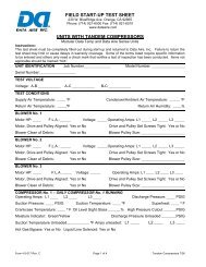
5.0 Electronically Commutated Motors (EC Motors)<br />
5.1 Start-up with EC motors/Plug fans ...................................................................... 13<br />
5.2 Testing ................................................................................................................. 14<br />
5.3 Protective Feature ............................................................................................... 14<br />
5.4 <strong>Maintenance</strong> ........................................................................................................ 14<br />
3
Table of Contents, cont’d<br />
6.0 REGULAR MAINTENANCE ITEMS .................................................................. 15<br />
6.1 Filters ................................................................................................................... 15<br />
6.2 Humidifi er Canisters ............................................................................................ 15<br />
6.3 Fuses ................................................................................................................... 15<br />
6.4 Heating Elements ................................................................................................ 15<br />
7.0 WARRANTY ....................................................................................................... 16<br />
8.0 CONTACT DATA AIRE ...................................................................................... 17<br />
MONTHLY MAINTENANCE INSPECTION CHECKLIST .................................... 19<br />
QUARTERLY MAINTENANCE INSPECTION CHECKLIST ............................... 20<br />
INDEX ................................................................................................................. 21<br />
4
1.0 INSTALLATION<br />
There is no intent on the part of <strong>Data</strong> <strong>Aire</strong>, Inc. to defi ne local codes or statutes which<br />
may supercede common trade practices. The manufacturer assumes no responsibility<br />
for their interpretation. Consult local building codes <strong>and</strong> the National Electrical Code for<br />
special installation requirements.<br />
1.1 Room Considerations<br />
Precision air conditioning equipment is designed to control spaces within close tolerances<br />
of temperature <strong>and</strong> humidity. However, the room must be built with a proper vapor barrier. A fi lm<br />
of polyethylene is often used on walls <strong>and</strong> ceilings. Walls <strong>and</strong> fl oors must also be painted with a<br />
vapor-seal paint. Failure to provide a vapor barrier can compromise space conditions.<br />
Introduction of outside air into the space should be minimized. Outside air in excess of 5% of<br />
the total circulated air volume can have a signifi cant effect on the overall space conditions <strong>and</strong> result<br />
in poor space control.<br />
1.2 Inspection<br />
This <strong>Data</strong> <strong>Aire</strong> unit has been factory run-tested <strong>and</strong> has gone through a comprehensive<br />
inspection prior to its packaging <strong>and</strong> shipment to ensure that it arrives in excellent condition. However,<br />
shipping damage can occur <strong>and</strong> a visual inspection of the outer crating immediately upon delivery<br />
should be performed.<br />
Note any external damage or other transportation damage on the freight carrier’s forms. Inspect<br />
the unit itself for internal damage. A claim should be fi led with the shipping company if the equipment<br />
is damaged or incomplete.<br />
Loose items such as remote control panels, disconnect switch h<strong>and</strong>les, spare belts <strong>and</strong><br />
spare fi lters are packed inside the unit. Refer to the yellow shipping tag located on the unit door for<br />
details.<br />
1.3 Rigging<br />
Freight damage claims are the responsibility of the purchaser. Action to recover losses<br />
should be fi led immediately. Please notify factory personnel of any claims.<br />
Move the unit in its upright position to the installation site. It is recommended that the unit<br />
be protected from damage to the decorative doors during any storage or moving. Removal of the<br />
decorative doors is easily accomplished <strong>and</strong> may be done when moving equipment.<br />
The shipping skid should be left in place if the unit is being moved with a forklift. If the unit is<br />
being lifted, use spreader bars to prevent damage to the doors <strong>and</strong> panels.<br />
The unit has 3/4” holes in the shipping skid to which casters with 3/4” stems can be attached.<br />
This allows easy movement down halls, into elevators <strong>and</strong> through doorways. If clearance is a<br />
5
problem the casters may be inserted directly into the bottom of the 1” tubular steel corner posts at<br />
the bottom of the unit.<br />
Warning: Improper lifting or moving of equipment may result in damage to decorative<br />
doors, panels or frame members.<br />
1.4 Locating the Unit<br />
When installing the unit, sufficient space must be allowed for airflow clearance, wiring, plumbing,<br />
<strong>and</strong> service access. It is recommended that each side <strong>and</strong> front have a clearance of at least 36” to<br />
allow the doors to swing open <strong>and</strong> for servicing the unit.<br />
The doors on some sides may not require as much service clearance. Refer to the particular<br />
unit component breakdown drawings for assistance. Rear clearance is not required, but 1” to 2” of<br />
clearance is suggested.<br />
For the best air distribution, the unit should be centered against the longest wall, as close to<br />
the heat load as possible, unless the unit is ducted. The unit should not be placed near any corner<br />
of the room or at the end of a long, narrow room. Multiple units should be evenly spaced, as far<br />
apart as possible.<br />
Note to Installing Contractor: Condensation formation <strong>and</strong> frequent humidifi er fl ushing<br />
are normal functions of this equipment. Proper drain connections must be made to<br />
ensure proper removal. Unit will require water connections for condensate removal <strong>and</strong><br />
possibly for humidifier makeup water, chilled water <strong>and</strong>/or hot water. Installation of units<br />
above equipment that could sustain water damage should be avoided.<br />
1.4.1 Downflow Units<br />
Downfl ow units will typically sit on an elevated fl ooring system known as a raised fl oor. The<br />
unit discharges air downward which pressurizes the raised fl oor <strong>and</strong> channels upward through<br />
perforated fl oor tiles. Location <strong>and</strong> quantity of perforated tiles will dictate proper air distribution. If<br />
the raised fl oor is strong enough to support the unit <strong>and</strong> local codes permit, the unit can be placed<br />
directly on top with cutouts made for the discharge openings.<br />
There may be additional support required in the form of adjustable jackst<strong>and</strong>s. These are<br />
adjustable, threaded leveling rods which support the unit in each of the corners <strong>and</strong> in the center on<br />
longer length units. Tighten the locknuts provided with each jackst<strong>and</strong>. The baseplate can rest on<br />
the fl oor or on vibration isolation pads.<br />
Floorst<strong>and</strong>s are also a way of supporting the unit. These are ordered to the height of the fl oor<br />
with leveling rods to allow adjustment. The fl oorst<strong>and</strong> has lips in each corner to align with the unit<br />
which is placed on top. It is recommended that the unit frame be bolted or screwed to the fl oorst<strong>and</strong><br />
from below. Local building codes may dictate this procedure. After installation, the raised fl oor is<br />
typically built around the unit.<br />
The raised floor serves as the distribution plenum for air on downflow units. Cables, piping,<br />
wiring raceways, inadequate floor height <strong>and</strong> any other restrictions can inhibit proper airflow.<br />
Care should be taken to avoid restrictions.<br />
6
1.4.2 Upflow Units<br />
Upfl ow units will typically be supported by vibration isolation pads <strong>and</strong>/or fl oorst<strong>and</strong>s which<br />
<strong>and</strong> may also include leveling screws. An air discharge plenum may be factory provided which ships<br />
loose <strong>and</strong> must be attached at the top of the unit frame.<br />
Alternately, an air distribution plenum must be fi eld fabricated with supply grilles to distribute<br />
the air. Units are shipped with a drive package to overcome external static pressure. Adjustments<br />
to the blower speed may be required to adjust to actual conditions.<br />
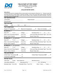
1.5 Paperwork<br />
Each <strong>Data</strong> <strong>Aire</strong> unit ships with a start-up sheet that should be completed during installation. Also<br />
included in the paperwork is a warranty/information packet that provides important wiring diagrams,<br />
specifi c component literature, warranty registrations cards <strong>and</strong> other valuable paperwork, including<br />
a copy of this Installation/<strong>Operation</strong> <strong>and</strong> <strong>Maintenance</strong> manual.<br />
A yellow tag is attached to the outside decorative door to indicate articles that may have been<br />
packaged <strong>and</strong> shipped loose within the unit cabinet. Typically this would be jackst<strong>and</strong>s, condensate<br />
pumps <strong>and</strong> other loose components that are not factory mounted.<br />
1.6 Storage<br />
Your <strong>Data</strong> <strong>Aire</strong> equipment comes ready for immediate installation. In some instances in may be<br />
necessary to store the equipment for a period of time. If you must store the equipment it should<br />
be done in a dry area, out of the weather, protected from damage by other equipment in storage or<br />
transportation equipment, never stacked, <strong>and</strong> avoid frequent relocation.<br />
If equipment is stored for longer than 30 days special precautions must be taken to avoid coil damage.<br />
All coils should be charged <strong>and</strong> sealed with a low pressure (1-25 psig) inert gas, such as nitrogen.<br />
This prevents contaminates from entering the coils; then when the seal is broken at installation, the<br />
rush of escaping gas verifies the coil is still leak free. If coils are not charged <strong>and</strong> sealed condensation<br />
mixes with air pollutants forming a weak acid <strong>and</strong> over time can cause pin hole leaks to develop in<br />
the coil tubes.<br />
When equipment is installed after storage caution should be taken to inspect <strong>and</strong> replace, if required,<br />
rubber hoses <strong>and</strong> belts. All moving parts, such as blowers <strong>and</strong> motors, should be h<strong>and</strong> tested to<br />
ensure that they are free <strong>and</strong> clear prior to start-up. Finally, verify that all lubrication is fresh <strong>and</strong><br />
full.<br />
It is the responsibility of the installing contractor to return the start-up sheet <strong>and</strong> warranty<br />
registration card to <strong>Data</strong> <strong>Aire</strong> for proper activation of the unit warranty. Failure to do so<br />
may cause delays <strong>and</strong> in some cases void the warranty.<br />
7
2.0 PIPING<br />
2.1 <strong>Chilled</strong> Water Unit Piping<br />
The required fi eld installed water pipe sizes may or may not be the same as the connection<br />
sizes at the unit. This will depend on the length of pipe <strong>and</strong> the calculated pressure drop of peripheral<br />
components.<br />
Shutoff valves should be installed within a few feet of the inlet <strong>and</strong> outlet connections of the<br />
unit to allow the unit to be isolated for service. A fi ll valve with a hose bib connection should also be<br />
used on the supply line or return line at the unit to allow the unit to be drained.<br />
Water temperature <strong>and</strong> worst-case room temperature <strong>and</strong> humidity conditions should be used<br />
to determine whether external piping should be insulated. Typical water temperature is 45° F which<br />
is usually cold enough to cause pipes to sweat.<br />
Field pipe connections are typically made at the bottom of the unit. Punching holes in the back<br />
panel <strong>and</strong> making a 90° turn out the back of the unit is also acceptable. In some cases provisions<br />
have been made to route the pipes out the right or left side or out the top of the unit. Openings should<br />
not be made in the hinged decorative doors as this could prevent the door from swinging open.<br />
St<strong>and</strong>ard chilled water units have a 3-way chilled water valve. An option for a 2-way valve<br />
is also available. In either case the water connections to the unit should be made so there is a<br />
counterfl ow between the water <strong>and</strong> air. Field water pipe connections are labelled but the counterfl ow<br />
should also be verifi ed before making fi eld connections.<br />
One of the most common problems in a chilled water system is the presence of air in the chilled<br />
water loop. Air vents must be installed in various locations in the piping system to purge the air.<br />
2.1.1 Connection sizes, <strong>Chilled</strong> Water units<br />
Water In <strong>and</strong> Out<br />
Water In <strong>and</strong> Out<br />
Evaporator Model Connections, OD Evaporator Model Connections, OD<br />
GFCx007 1 1/8” GFCx053 1 5/8”<br />
GFCx011 1 1/8” GFCx063 2 1/8”<br />
GFCx014 1 1/8” GFCx077 2 1/8”<br />
GFCx018 1 1/8” GFCx091 2 1/8”<br />
GFCx025 1 1/8” GFCx106 2 1/8”<br />
GFCx032 1 1/8” GFCx158 2 5/8”<br />
GFCx039 1 5/8” GFCx176 2 5/8”<br />
X = D-Downfl ow, U-Upfl ow GFCx211 3 1/8”<br />
2.2 <strong>Chilled</strong> Water Valve Ratings<br />
All chilled water valves used on g-Force series models 025 to 176 kW use chilled water valves<br />
that are rated at 400 psi operating pressure. The chart on the next page gives the valve size <strong>and</strong> Cv<br />
rating on 3-way valves for all unit models. The same information plus maximum close off pressure<br />
for optional 2-way valves is also indicated<br />
8
2.2.1 3-Way <strong>Chilled</strong> Water Valves<br />
Unit Model Valve Size Valve CV<br />
GFCx025 1” 10.0<br />
GFCx032 1” 10.0<br />
GFCx039 1-1/4” 10.0<br />
GFCx046 1-1/2” 19.0<br />
GFCx053 1-1/2” 19.0<br />
GFCx063 2” 46.0<br />
GFCx077 2” 46.0<br />
GFCx091 2” 46.0<br />
GFCx106 2” 46.0<br />
GFCx141 2” 46.0<br />
GFCx158 2” 46.0<br />
GFCx176 2” 46.0<br />
GFCx211 2” 83.0<br />
2.2.2 2-Way <strong>Chilled</strong> Water Valves<br />
Close-off<br />
Unit Model Valve Size Valve CV Pressure, psi<br />
GFCx025 1” 10.0 200<br />
GFCx032 1” 10.0 200<br />
GFCx039 1 1/4” 10.0 200<br />
GFCx046 1 1/2” 19.0 200<br />
GFCx053 1 1/2” 19.0 200<br />
GFCx063 2” 46.0 200<br />
GFCx077 2” 46.0 200<br />
GFCx091 2” 46.0 200<br />
GFCx106 2” 46.0 200<br />
GFCx141 2” 46.0 200<br />
GFCx158 2” 46.0 200<br />
GFCx176 2” 46.0 200<br />
GFCx211 2” 85.0 100<br />
2.3 Condensate Drain Piping<br />
Every indoor unit has a 3/4” copper stub provided for condensate removal. A union is<br />
recommended at the fi eld connection which will permit easy disconnection from the unit for<br />
cleaning.<br />
A trap should be built into the drain line to prevent air from backing up into the unit. Drain lines<br />
should be pitched downward not less than 1/4” for each ten feet of horizontal run. Do not reduce the<br />
size of the drain line.<br />
Some applications have no convenient means of allowing a gravity drain. In this case, a<br />
condensate pump can be used. These come either factory mounted or shipped loose. Factory<br />
mounted condensate pumps do not require a separate power source.<br />
9
Condensate pumps shipped loose (or field provided) typically require a dedicated 110 volt power<br />
source. Field pipe connections must be made to the pump discharge connection. A check valve must<br />
be installed to prevent short cycling. See also condensate pump electrical requirements in Section 3.9.<br />
2.4 Humidifier Piping<br />
2.4.1 Steam Generator Humidifier<br />
The st<strong>and</strong>ard humidifier on <strong>Data</strong> <strong>Aire</strong> systems is a steam generator type with a disposable cylinder.<br />
The humidifier makeup water should be brought to the humidifier through the field connection opening<br />
using 1/4” copper tubing. A compression fi tting is provided at the humidifi er.<br />
A shutoff valve should be provided outside the air conditioner to allow disconnection for service.<br />
An in-line water pressure regulator <strong>and</strong> strainer should be installed. Water pressure should be set<br />
between 20 <strong>and</strong> 50 PSI.<br />
The humidifi er has a drain at the bottom which is factory piped to the main condensate drain line.<br />
The dispersion tube also has a drain line. No additional fi eld piping is required.<br />
2.4.2 Dry Steam Humidifier<br />
The optional dry steam type humidifi er requires a strainer on the inlet steam line. An outlet<br />
connection with a fi eld-provided steam trap is also required. Steam pressure is typically 10-15 psi.<br />
2.5 Leak Testing<br />
No installation is complete until the entire system has been thoroughly checked for leaks. This<br />
includes water lines, fl are fi ttings, pressure controls, <strong>and</strong> Shrader fi ttings.<br />
Check all humidifi er water makeup lines, condensate lines, condensate pumps, chilled water<br />
lines.<br />
Tightening of fi ttings <strong>and</strong> valves is the responsibility of the installing contractor.<br />
10
3.0 ELECTRICAL CONNECTIONS<br />
Before proceeding with the electrical connections, make certain that the volts, hertz, <strong>and</strong><br />
phase correspond to that specified on the unit electrical nameplate. Use copper conductors<br />
only.<br />
3.1 Electrical Service<br />
Check to be sure the service provided by the utility is suffi cient to h<strong>and</strong>le the additional load<br />
imposed by this equipment.<br />
3.2 Nameplate Ratings<br />
Refer to the unit electrical nameplate for equipment electrical requirements. Minimum circuit<br />
ampacity, (MCA) also known as wire sizing amps, will dictate the minimum required wire gauge.<br />
Maximum Overcurrent Protection (MOP) device amps will dictate the maximum circuit breaker or<br />
fuse size.<br />
3.3 Grounding<br />
The unit cabinet must have an uninterrupted true earth ground. An electrical ground wire of<br />
adequate size must be connected to the ground lug provided inside the main electrical box.<br />
3.4 Voltage Tolerance<br />
The supply voltage to the unit must be within 10% of the voltage indicated on the unit electrical<br />
nameplate. Phase to phase imbalance must not exceed 3%. The local utility company should be<br />
contacted for correction of improper line voltage. Deviation from voltage ratings can cause premature<br />
failures <strong>and</strong> possibly void unit warranties.<br />
Check the wiring connections in the unit control panel to ensure they are tight. Screw<br />
terminals may become loose in transit. Tightening of wiring connections is the responsibility<br />
of the installing contractor.<br />
3.5 Remote Shutdown<br />
Every <strong>Data</strong> <strong>Aire</strong> chilled water unit has remote shutdown contacts. These are intended for a field<br />
supplied dry contact or switch to be wired across two terminals. When the contact or switch opens,<br />
the control circuit power is interrupted <strong>and</strong> the unit shuts down, including the control panel. The control<br />
circuit is 24 VAC <strong>and</strong> the field provided contact or switch should have a minimum rating of 10 amps.<br />
The remote shutdown contacts are always terminals #1 <strong>and</strong> #2 on the terminal block designated<br />
TB1. The unit will ship with a factory wired metal jumper clip that connects terminal #1 to terminal<br />
#2. Remove this clip prior to installing the fi eld wires.<br />
3.6 Remote Alarm Contacts<br />
The DAP III, microprocessor control panel provides a remote alarm output contact that can be<br />
fi eld accessed on terminals #11 <strong>and</strong> #13 of terminal block TB1. This is a Normally Open, Close on<br />
Alarm, dry contact, intended to be used in a control circuit not exceeding 5 amps at 24 VAC.<br />
This programmable output contact will close on a failure <strong>and</strong> remain closed until the alarm is no longer<br />
present. Three additional alarm output contacts come with the optional relay module. The terminal<br />
designations for these alarm output contact pairs are #40 <strong>and</strong> #42; #43 <strong>and</strong> #45; <strong>and</strong> #48 <strong>and</strong> #50.<br />
11
3.7 Remote Sensors<br />
Remote sensors are optional. Although existing unit mounted sensors can be removed for remote<br />
mounting, the remote sensor option provides a more convenient means of fi eld installation. This is<br />
because the sensors are already connected to a predetermined length of cable <strong>and</strong> come mounted<br />
in a remote sensor enclosure. The temperature <strong>and</strong> humidity sensors require a total of fi ve wires,<br />
these should be a twisted, shielded cable.<br />
3.8 Condensate Pumps<br />
Condensate pumps which ship loose normally require a separate source of 110 volt power. Always<br />
check the pump power requirements before connecting power. Condensate pumps are available in<br />
other voltages.<br />
Condensate pumps may also come unit mounted <strong>and</strong> powered. While no outside power source<br />
is required, fi eld piping is still a requirement.<br />
Condensate pumps are wired to display a “High Condensate Water Level” alarm. The wiring for<br />
this must be done in the fi eld on pumps that ship loose. Factory mounted pumps come pre-wired.<br />
3.9 Condensate Probe<br />
A condensate probe for sensing underfl oor water is included with this unit. This comes in a plastic<br />
bag, with about 15 feet of coiled-up wire. The probe is a fl at plate that is typically placed below the<br />
unit in a location where water is likely to accumulate.<br />
Place the probe fl at on the fl oor on top of a thin layer of non-conductive silicone. Secure the<br />
attached wires where necessary. A longer length of wire may be used if required.<br />
Note: Failure to uncoil the length of wire attached to the condensate probe can result<br />
in a nuisance water-detected alarm. If the probe is not going to be used it should be<br />
disconnected.<br />
3.10 Water Sensing Cable<br />
Another option for water sensing is the Water Detection Cable. This is a long cable that can<br />
sense moisture anywhere along its length. It is typically placed below the unit in a rectangular pattern<br />
that matches the perimeter of the unit.<br />
12
4.0 CONTROLS<br />
4.1 DAP III Microprocessor Control Panel<br />
The st<strong>and</strong>ard controls on all g-Force Series equipment is the DAP III microprocessor control panel.<br />
This state-of-the-art control panel has a separate manual that goes into extensive detail regarding<br />
functions, features, programming, <strong>and</strong> troubleshooting.<br />
The DAP III microprocessor control panel has an entire manual dedicated to its use <strong>and</strong><br />
operation. This manual must be referenced to complete a thorough unit installation.<br />
Start-up is not complete until the DAP III control panel settings are established.<br />
4.2 Wiring Diagrams<br />
Every <strong>Data</strong> <strong>Aire</strong> unit comes with a wiring diagram. These diagrams are ‘ladder’- type schematics<br />
intended for service personnel. The intent is to allow the technician to underst<strong>and</strong> the wiring details<br />
associated with the electrical components <strong>and</strong> how they interface with the DAP III control panel as<br />
well as peripheral equipment.<br />
<strong>Data</strong> <strong>Aire</strong>’s chilled water unit wiring diagrams will have a drawing number which starts out with<br />
the three letter designation, “GFC”. An example of a typical diagram, GFC-S-813, is shown on page<br />
18.<br />
5.0 ELECTRONICALLY COMMUTATED MOTORS (EC MOTORS)<br />
Electronically Commutated (EC) motors with “Plug fan” are st<strong>and</strong>ard on all g-Force units.<br />
Note: The plug fan modules are powered by high voltage input line power (i.e.<br />
208-230V/3PH/60HZ or 460V/3PH/60HZ) <strong>and</strong> speed is set from 10V DC control signal<br />
from the unit’s microprocessor controller - <strong>Data</strong> Alarm Processor-III (DAP-III).<br />
Fan speed is factory set based on order.<br />
Fan speed can be changed in 1% increments through the unit’s microprocessor control (DAP-III).<br />
See the DAP-III operation manual (Menu Group 3, Sub-Menu 3-17) for details <strong>and</strong> recommended<br />
settings.<br />
5.1 START-UP WITH EC MOTORS/PLUG FANS<br />
Using the DAP-III manual switch operation will not bring the fans to full speed. Enabling the<br />
BLOWER manual mode switch inside on controller engages the contactors powering the high voltage<br />
to the plug fans but sets the control signal to 0V.<br />
Enabling any other manual mode switch will likewise disable all control outputs from the DAP-III<br />
panel resulting in full manual mode operation <strong>and</strong> setting the plug fans to 0V.<br />
13
5.2 TESTING<br />
To test the plug fan modules in manual mode, wire a 9 volt battery across the plug fan control<br />
signal (Analog Module Output 1). Be certain to disconnect both terminals ( + <strong>and</strong> - ) from the Analog<br />
Module. This will enable the fan control signal at approximately 90%. The fans will spin at near full<br />
speed if there contactors are enabled.<br />
5.3 PROTECTIVE FEATURES<br />
EC motors have built-in protective features that include the following:<br />
Over-Temperature protection of the (motor) electronics,<br />
Over-Temperature protection of the motor,<br />
Locked rotor protection,<br />
Phase failure detection,<br />
Under-voltage detection,<br />
Short-circuit protection.<br />
If any of the conditions exist, the motor stops electronically <strong>and</strong> an alarm (NO AIRFLOW) will be<br />
energized <strong>and</strong> displayed on the unit’s microprocessor screen. The motor will start up automatically.<br />
To reset, the power supply has to be switched OFF for a minimum of twenty seconds.<br />
If for any reason the rotor is blocked, the motor will electronically switch off. Before looking<br />
for any blockage make certain to power don the unit. Once the blockage is cleared the<br />
motor will automatically restart when powered on.<br />
EC motors have under voltage protection. If the power supply voltage falls below ˜150 VAC/3Φ<br />
(for 230 volt motors) or ˜290 VAC/3Φ (for 460 volt motors) for a minimum of fi ve (5) seconds, the<br />
motor will automatically switch off <strong>and</strong> an alarm (NO AIRFLOW) will be energized <strong>and</strong> displayed. If<br />
the power supply voltage returns to the correct values, the motor will automatically restart.<br />
Note: The unit’s control panel (DAP-III) has a time delay before the NO AIRFLOW<br />
alarm is energized. It is adjustable from 5 to 180 seconds (in 5 second increments). On<br />
sites where a voltage problem is known to exist, the delay can be adjusted to eliminate<br />
“nuisance” alarms until the problem is corrected. See Menu Group 4 (ALARMS), Sub-<br />
Menu 4-24 (NO AIR FLOW ALARM TIME DELAY) in the DAP-III operation manual.<br />
5.4 MAINTENANCE<br />
<strong>Maintenance</strong> is not required on EC motor/plug fan modules. The motors are sealed, have<br />
maintenance free ball bearings <strong>and</strong> permanent lubrication. The only acceptable service is replacement.<br />
14
6.0 REGULAR MAINTENANCE ITEMS<br />
6.1 Filters<br />
Filters should be checked on a regular basis <strong>and</strong> changed when they become dirty. This will<br />
ensure effi cient operation of the unit. Although the unit has a dirty fi lter alarm, this should not be<br />
relied on as the only determinant for replacing fi lters. A maladjusted fi lter differential pressure switch<br />
may not give a proper indication of a clogged fi lter.<br />
To check the fi lter differential pressure switch for proper adjustment, temporarily cover about<br />
75% of the return air opening using heavy cardboard or similar material. The alarm should energize<br />
when 75% of the air is blocked, simulating dirty fi lters. If the alarm energizes prematurely or does not<br />
energize at all, the pressure switch should be adjusted. Doors must remain closed when determining<br />
if an adjustment is necessary.<br />
Spare fi lters should be kept in stock as these tend to be a frequently replaced maintenance item.<br />
Filters may require changing as often as monthly. Note also that construction dust on new installations<br />
will quickly clog new fi lters.<br />
Filters that require changing can restrict airfl ow <strong>and</strong> create problems such as poor air<br />
distribution.<br />
6.2 Humidifier Canisters<br />
Steam generator type humidifi er is st<strong>and</strong>ard on g-Force Series of equipment. There is no<br />
maintenance required other than to replace the canister as required. This frequency will depend on<br />
usage <strong>and</strong> water type. A set of manufacturer’s instructions for the humidifi er is sent as part of the<br />
paperwork placed inside the unit when it ships.<br />
6.3 Fuses<br />
Fuses may occasionally require changing especially with installations where the voltage is not<br />
consistent. Drops in voltage can create brief periods of high amp draw, causing fuses to blow. Always<br />
replace fuses with those of the equivalent rating with regard to: 1) amperage, 2) voltage, <strong>and</strong> 3)<br />
speed. For instance motors are inductive loads which require time delay fuses. Electric reheat <strong>and</strong><br />
humidifi ers are resistive loads requiring fast acting fuses.<br />
6.4 Heating Elements<br />
Heating elements do not normally require maintenance. However sometimes they may accumulate<br />
a fi lm of dust or dirt when unused for extended periods of time. When energized, the burning debris<br />
can create smoke or unpleasant odor. To help avoid this, periodic cleaning is recommended.<br />
15
7.0 Warranty Policy<br />
Seller warrants its equipment to Buyer to be free from defects in material <strong>and</strong> workmanship for a<br />
period of eighteen (18) months from date of shipment, as long as equipment is utilized under normal<br />
conditions <strong>and</strong> service <strong>and</strong> is properly installed; however, the warranty shall not be applicable to any<br />
of the following items: refrigerant, belts, fi lters, humidifi er, heaters not regularly cleaned, light bulbs,<br />
<strong>and</strong> any other items either consumed or worn out by normal wear <strong>and</strong> tear, or by conditions beyond<br />
Seller’s control, including (without limitation as to generally) polluted or contaminated air or water.<br />
The Seller’s obligation under this warranty is limited solely to the repair or replacement, at Seller’s<br />
options, of any part or parts thereof which shall, within eighteen (18) months from date of shipment<br />
of the equipment to the original purchaser be returned to the factory, transportation charges prepaid,<br />
which upon examination shall disclose to the Seller’s satisfaction to have been defective under<br />
normal use <strong>and</strong> service. This agreement to repair or replace defective parts is expressly in lieu of all<br />
other warranties, expressed or implied <strong>and</strong> all other obligations or liabilities on the part of Seller <strong>and</strong><br />
Seller neither assumes nor authorizes any other person to assume for it any liability or obligation in<br />
connection with the sales or service of its equipment, except said repair or replacement of defective<br />
parts set forth above.<br />
This warranty does not include any labor charges for work done outside of the factory for replacement<br />
of parts, adjustments, repairs, or any other work. Seller’s liability does not include any resulting<br />
damage to persons, property, equipment, goods or merch<strong>and</strong>ise arising out of any defect in or failure<br />
of any equipment of its manufacture <strong>and</strong> Buyer hereby waives any claim against Seller arising out<br />
of such claim. This warranty shall not cover the repair or replacement of any equipment which has<br />
been repaired or altered outside of the factory in any way or which has been subject to negligence,<br />
misuse, or abuse, or to pressures in excess of stated limits.<br />
This warranty applies only to the original purchaser of the equipment <strong>and</strong> does not extend, expressly or<br />
by implication, to the third parties or others without the specific written approval <strong>and</strong> acknowledgment<br />
of Seller. Buyer’s exclusive remedy <strong>and</strong> Seller’s maximum liability for any <strong>and</strong> all loss, injury, damage,<br />
costs, or expense arising from any defect covered by this warranty shall be limited to the repair or<br />
replacement, but not the installation of any defective material, F.O.B., Seller’s plant; provided however,<br />
that Seller shall not be required to replace any part or component (a) which can be repaired, or (b)<br />
unless Buyer has given Seller immediate written notice that replacement or repair. In addition, Seller<br />
shall not be liable for any cost or expense of replacement or repair contracted for by Buyer with<br />
any third person, unless, <strong>and</strong> then only to the extent that Seller authorizes in writing, such costs or<br />
expense.<br />
Seller shall not be liable for any direct, indirect incidental, consequential, or other form of loss, injury,<br />
damage, cost, or expense, whether caused by delay, failure, or performance, breach of warranty,<br />
or by any cause whatsoever.<br />
Seller’s obligation under this warranty shall be void if Buyer fails: (a) without legal justifi cation to pay<br />
Seller, when due, the full purchase price for the equipment sold hereunder; or (b) to have the equipment<br />
sold hereunder installed, maintained, <strong>and</strong> serviced by competent personnel <strong>and</strong> in accordance with<br />
Seller’s instructions.<br />
16
8.0 Contact <strong>Data</strong> <strong>Aire</strong><br />
Address:<br />
<strong>Data</strong> <strong>Aire</strong> Inc.<br />
230 W. BlueRidge Avenue<br />
Orange, CA 92865<br />
Phone<br />
714-921-6000<br />
800-347-AIRE (2473)<br />
Toll Free<br />
Fax:<br />
714-921-6010 Main<br />
714-921-6011 Engineering<br />
714-921-6022 Part Sales<br />
E-mail:<br />
service@dataaire.com<br />
tech_support@dataaire.com<br />
engineering@dataaire.com<br />
sales@dataaire.com<br />
Service<br />
Technical Support<br />
Engineering<br />
Sales<br />
Web site:<br />
www.dataaire.com<br />
Job information:<br />
Model Number: G__ __ __ __ __ __ __ - __ __<br />
Serial Number: __ __ __ __ - __ __ __ __ - __<br />
Job number: _______________________________________<br />
Date installed: ___ / ___ / 201___<br />
Installing Contractor: ________________________________<br />
17
<strong>Data</strong> <strong>Aire</strong>, Inc.<br />
Monthly <strong>Maintenance</strong> Inspection Checklist<br />
Model No. __________________ Serial No. ____________________<br />
Prepared by: _______________ Date: ___ / ___/ 201__<br />
Air Filters<br />
___ Check for restricted air fl ow<br />
Electrical Panel<br />
___ Check contactor operation<br />
___ DAPIII control panel operations<br />
Air Distribution Section<br />
___ Check for restriction in grille(s)<br />
Equipment Runtimes<br />
Blower<br />
_________ hrs<br />
Condensate Drain <strong>and</strong> Pump (if applicable) Reheat No. 1<br />
_________ hrs<br />
___ Check for water leaks<br />
Reheat No. 2<br />
_________ hrs<br />
___ Check for restricted air fl ow<br />
Reheat No. 3<br />
_________ hrs<br />
___ Pump operation<br />
Humidifi er<br />
_________ hrs<br />
Dehumidifi cation _________ hrs<br />
Steam Generating Humidifier<br />
<strong>Chilled</strong> Water Cooling _________ hrs<br />
___ Check canister for deposits <strong>and</strong> water level<br />
___ Check condition of steam hose <strong>and</strong> clamps ___ Reset all to read zero runtimes<br />
Infrared Humidifier (if applicable)<br />
___ Check humidifi er lamps<br />
Temperature/Humidity set at: ___° ___% RH<br />
___ Check pan for mineral deposits<br />
Notes: _______________________________________________________________________<br />
______________________________________________________________________________<br />
______________________________________________________________________________<br />
______________________________________________________________________________<br />
______________________________________________________________________________<br />
______________________________________________________________________________<br />
______________________________________________________________________________<br />
______________________________________________________________________________<br />
______________________________________________________________________________<br />
______________________________________________________________________________<br />
______________________________________________________________________________<br />
______________________________________________________________________________<br />
______________________________________________________________________________<br />
19
<strong>Data</strong> <strong>Aire</strong>, Inc.<br />
Quarterly <strong>Maintenance</strong> Inspection Checklist<br />
Model No. _______________________ Serial No. ___________________________<br />
Prepared by: _____________________ Date: ___ / ___/ 200__<br />
Air Filters<br />
____ Check for restricted air fl ow<br />
____ Check fi lter differential switch<br />
____ Wipe fi lter rack section clean<br />
Air Distribution Section<br />
____ Check for restriction in grille(s)<br />
Condensate Drain <strong>and</strong> Pump (if applicable)<br />
____ Check for water leaks <strong>and</strong> restricted fl ow<br />
____ Pump operation<br />
Steam Generating Humidifier<br />
____ Check canister for deposits <strong>and</strong> water level<br />
____ Check condition of steam hose <strong>and</strong> clamps<br />
____ Check drain <strong>and</strong> fi ll valve for deposits<br />
Infrared Humidifier (if applicable)<br />
____ Check humidifi er lamps<br />
____ Check pan for mineral deposits<br />
____ Check high limit switch operation<br />
____ Check drain timer operation<br />
____ Check drain valve operation<br />
Reheat<br />
____ Check reheat element(s) for dust<br />
____ Check high limit switch operation<br />
Electrical Panel<br />
____ Check fuses<br />
____ Check contactor operation<br />
____ Check all electrical connections<br />
____ Check operation sequence<br />
DAPIII control panel operations<br />
____ Check calibration of temperature sensor (7-1*)<br />
____ Check calibration of humidity sensor (7-2*)<br />
____ Check calibration of discharge air sensor (7-3*)<br />
____ Check calibration of chilled water temperature<br />
sensor (7-4*)<br />
* DAP III group 7 submenus. Options 7-3 <strong>and</strong> 7-4 are optional<br />
<strong>and</strong> may not be installed in all units<br />
Equipment Runtimes<br />
Blower<br />
____________ hrs<br />
Reheat No. 1 ____________ hrs<br />
Reheat No. 2 ____________ hrs<br />
Reheat No. 3 ____________ hrs<br />
Humidifi er<br />
____________ hrs<br />
Dehumidifi cation ____________ hrs<br />
<strong>Chilled</strong> Water Cooling ____________ hrs<br />
____Reset all to read zero runtimes<br />
Temperature/Humidity set at: _____° _____% RH<br />
Notes: ______________________________________________________________________________________<br />
_____________________________________________________________________________________________<br />
_____________________________________________________________________________________________<br />
_____________________________________________________________________________________________<br />
_____________________________________________________________________________________________<br />
_____________________________________________________________________________________________<br />
_____________________________________________________________________________________________<br />
_____________________________________________________________________________________________<br />
_____________________________________________________________________________________________<br />
_____________________________________________________________________________________________<br />
_____________________________________________________________________________________________<br />
_____________________________________________________________________________________________<br />
_____________________________________________________________________________________________<br />
_____________________________________________________________________________________________<br />
_____________________________________________________________________________________________<br />
20
- A -<br />
Air Filters ............................................. 14<br />
- C -<br />
Cable, Water Sensing ......................... 12<br />
Condensate Cable .............................. 12<br />
Condensate Probe ............................. 12<br />
Condensate Pumps .......................... 12<br />
Contact <strong>Data</strong> <strong>Aire</strong> ................................ 17<br />
Controls ............................................... 13<br />
DAP III Control Panel ..................... 13<br />
Wiring Diagrams ....................... 13, 18<br />
- D -<br />
DAP III Control Panel .......................... 13<br />
Differential Pressure Switch ................ 15<br />
- E -<br />
Electrical .............................................. 11<br />
Electronically Commutated Motors ..... 13<br />
- F -<br />
Field Piping ........................................... 8<br />
Condensate ...................................... 9<br />
Dry Steam Humidifi er ..................... 10<br />
Steam Generator Humidifi er .......... 10<br />
Field Wiring ......................................... 11<br />
Remote Alarm Contacts ................. 11<br />
Remote Sensors ............................ 12<br />
Remote Shutdown.......................... 12<br />
Filter<br />
Air ................................................... 15<br />
Floorst<strong>and</strong>s ........................................... 6<br />
Fuses .................................................. 15<br />
- G -<br />
Grounding ........................................ 11<br />
- H -<br />
Heat<br />
Electric ........................................... 15<br />
Reheat Elements............................ 15<br />
Humidifi er ...................................... 10, 15<br />
Canister .......................................... 15<br />
Dry Steam Humidifi er ..................... 10<br />
Steam Generator Humidifi er .... 10, 15<br />
INDEX<br />
- I -<br />
Inspection .............................................. 5<br />
Installation ..........................................5-7<br />
- J -<br />
Jackst<strong>and</strong>s ...........................................6<br />
- L -<br />
Leak Testing .......................................10<br />
Locating ................................................6<br />
- M -<br />
<strong>Maintenance</strong> .......................................15<br />
Filters ............................................15<br />
Fuses ...........................................15<br />
Heating Elements ..........................15<br />
Humidifi er Canisters ......................15<br />
- P -<br />
Paperwork ............................................7<br />
Piping See Field Piping<br />
Plug Fans ...........................................13<br />
Probe, Condensate ............................12<br />
- R -<br />
Reheat<br />
Elements .......................................15<br />
Electric ..........................................15<br />
Remote<br />
Alarm Contacts..............................11<br />
Sensors .........................................11<br />
Remote Shutdown.........................11<br />
Rigging .................................................5<br />
- V -<br />
Valves<br />
2-Way <strong>Chilled</strong> Water Valve ..............9<br />
3-Way <strong>Chilled</strong> Water Valve ..............9<br />
Humidifi er Makeup Water ..............10<br />
Voltage ...............................................11<br />
- W -<br />
Warranty .............................................16<br />
Water Sensing Cable .........................12<br />
Water Sensing Probe .........................12<br />
Wiring .................................................11<br />
21
Notes<br />
______________________________________________________________________________________<br />
______________________________________________________________________________________<br />
______________________________________________________________________________________<br />
______________________________________________________________________________________<br />
______________________________________________________________________________________<br />
______________________________________________________________________________________<br />
______________________________________________________________________________________<br />
______________________________________________________________________________________<br />
______________________________________________________________________________________<br />
______________________________________________________________________________________<br />
______________________________________________________________________________________<br />
______________________________________________________________________________________<br />
______________________________________________________________________________________<br />
______________________________________________________________________________________<br />
______________________________________________________________________________________<br />
______________________________________________________________________________________<br />
______________________________________________________________________________________<br />
______________________________________________________________________________________<br />
______________________________________________________________________________________<br />
______________________________________________________________________________________<br />
______________________________________________________________________________________<br />
______________________________________________________________________________________<br />
______________________________________________________________________________________<br />
______________________________________________________________________________________<br />
22
Notes<br />
______________________________________________________________________________________<br />
______________________________________________________________________________________<br />
______________________________________________________________________________________<br />
______________________________________________________________________________________<br />
______________________________________________________________________________________<br />
______________________________________________________________________________________<br />
______________________________________________________________________________________<br />
______________________________________________________________________________________<br />
______________________________________________________________________________________<br />
______________________________________________________________________________________<br />
______________________________________________________________________________________<br />
______________________________________________________________________________________<br />
______________________________________________________________________________________<br />
______________________________________________________________________________________<br />
______________________________________________________________________________________<br />
______________________________________________________________________________________<br />
______________________________________________________________________________________<br />
______________________________________________________________________________________<br />
______________________________________________________________________________________<br />
______________________________________________________________________________________<br />
______________________________________________________________________________________<br />
______________________________________________________________________________________<br />
______________________________________________________________________________________<br />
______________________________________________________________________________________<br />
23
230 W. BlueRidge Avenue<br />
Orange, CA 92865<br />
800-347-2473<br />
www.dataaire.com<br />
e-mail: sales@dataaire.com<br />
A Member of the CS Group of Companies<br />
© 2010 <strong>Data</strong> <strong>Aire</strong>, Inc.<br />
<strong>Data</strong> <strong>Aire</strong>, Inc. reserves the right to make design changes for the purpose of product improvement or to withdraw any design without notice.<br />
gFCWIOM-0310 Rev. B