MIXO - Ilme SpA
MIXO - Ilme SpA
MIXO - Ilme SpA

Create successful ePaper yourself
Turn your PDF publications into a flip-book with our unique Google optimized e-Paper software.
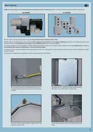
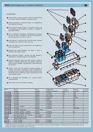
<strong>MIXO</strong> modular units for multipole connectors<br />
Application<br />
<strong>MIXO</strong><br />
The <strong>MIXO</strong> series is a system of modular units for special<br />
applications that uses the traditional ILME enclosures.<br />
Each enclosure can house different types of connections such<br />
as, for example: electric signals and contacts for the conduction<br />
of compressed air and liquids with pressure values of up to 8<br />
bars.<br />
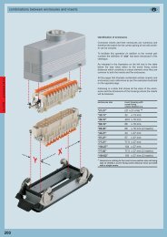
The inserts are arranged side by side to form a single compact<br />
block which is inserted into metallic frames with mandatory<br />
housings. Once the modules have been inserted and locked<br />
with the special tabs, the connector can then be inserted into the<br />
enclosure.<br />
The modular structure system makes it easy to access a series<br />
of contacts inserted in the frame (e.g., for substitution, checks or<br />
the addition of signals with new inserts for needs not foreseen<br />
during the initial installation) without having to disassemble the<br />
entire connector.<br />
The use of standard die-cast alluminium enclosures with degree<br />
of protection IP65 provides the possibility of innumerable<br />
applications.<br />
The <strong>MIXO</strong> series may be used with 5 different frame sizes.<br />
The following table lists the frames and the metallic enclosures<br />
that may be used.<br />
frames<br />
one or two-lever<br />
metallic enclosures<br />
CX 01 T size “49.16”<br />
CX 02 TM/TF size “44.27”<br />
CX 03 TM/TF size “57.27”<br />
CX 04 TM/TF size “77.27”<br />
CX 06 TM/TF size “104.27”<br />
CX 04 TM/TF (x 2) size “77.62”<br />
CX 06 TM/TF (x 2) size “104.62”<br />
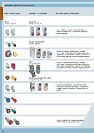
In addition, the <strong>MIXO</strong> series can be used with the COB series<br />
panel supports<br />
frames<br />
CX 02 TM/TF<br />
CX 03 TM/TF<br />
CX 04 TM/TF<br />
CX 06 TM/TF<br />
panel supports<br />
part No.<br />
fixed: COB 06 BC and COB TCQ<br />
mobile: COB TSF, COB TSFS and COB 06 CMS<br />
fixed: COB 10 BC and COB TCQ<br />
mobile: COB TSF, COB TSFS and COB 10 CMS<br />
fixed: COB 16 BC and COB TCQ<br />
mobile: COB TSF, COB TSFS and COB 16 CMS<br />
fixed: COB 24 BC and COB TCQ<br />
mobile: COB TSF, COB TSFS and COB 24 CMS<br />
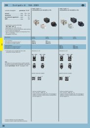
The <strong>MIXO</strong> series currently includes 6 different types of inserts.<br />
The field of application is provided in the table at the bottom of<br />
the next page.<br />
156
<strong>MIXO</strong> modular units for multipole connectors<br />
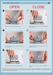
Characteristics<br />
electric contacts in silver-plated or gold-plated brass with<br />
connections to the conductors via crimping, spring clamp or<br />
axial screw.<br />
<br />
pneumatic contacts in plastic with insertion tube connection<br />
modular inserts of identical size with insertion system for<br />
forming the complete module and frame lock tab.<br />
inserts in self-extinguishing thermoplastic material, reinforced<br />
with glass fibre, UL 94-V0 approved, with a working<br />
temperature range of -40 °C to +125 °C.<br />
inserts in conformance with the requirements of the<br />
EN 61984 standard and certified and marked with the UL,<br />
CSA, CCC, GL, GOST marks.<br />
inserts with asymmetric guide rails to prevent incorrect<br />
coupling.<br />
position of contacts identified with numbers or codes on both<br />
sides of every insert.<br />
<br />
<br />
<br />
<strong>MIXO</strong><br />
male/female module carrier frames with mandatory housings<br />
and polarity, in die-cast zinc alloy.<br />
module lock tab, may be divided according to the number of<br />
modules used; guarantees a perfect stability of the modules<br />
during wiring and coupling/uncoupling of the connectors.<br />
asymmetric earth contacts (two for frame) with wide contact<br />
surface to prevent incorrect coupling; when two or more<br />
identical connectors of the <strong>MIXO</strong> series are used, coded pins<br />
prevent incorrect coupling (see pages 429, 430 and 431).<br />
captive frame fastening screws, with flexible spring washer.<br />
dummy module for unused frame slots.<br />
<br />
<br />
<br />
<br />
<br />
<br />
<br />
<br />
<br />
157
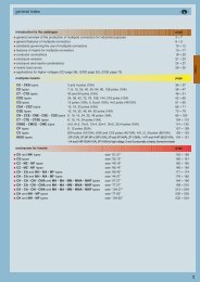
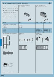
<strong>MIXO</strong> modular units for multipole connectors<br />
<strong>MIXO</strong><br />
inserts contact signal connectors and rated rated No. of frame<br />
type type tubes connections current A voltage V slots<br />
CX 01 YF/M main electric crimp 200 1000 2<br />
CX 01 YPEF/M PE --- crimp 200 --- 2<br />
CX 02 GF/M main electric crimp 100 1000 2<br />
CX 02 7F/M main electric crimp 70 1000 1<br />
CX 02 4AF/M main electric axial screw 40 1000 1<br />
CX 02 4BF/M main electric axial screw 40 1000 1<br />
CX 03 4F/M main electric crimp 40 400/690 1<br />
CX 03 4BF/BM main electric crimp 40 500 1<br />
CX 3/4 XDF/M main electric crimp 40/10 830 1<br />
CX 04 XF/M main electric crimp 40 830 1<br />
CX 05 SF/M main electric spring 16 400 1<br />
CX 06 CF/M main electric crimp 16 500 1<br />
CX 08 CF/M main electric crimp 16 400 1<br />
CX 20 CF/M main electric crimp 16 500 2<br />
CX 12 DF/M main / auxiliary electric crimp 10 250 1<br />
CX 17 DF/M main / auxiliary electric crimp 10 160 1<br />
CX 25 IF/M main / auxiliary elettrico crimp 4 50 1<br />
CX 02 HF/M main electric crimp 16 2900/5000 2<br />
CX 02 BF/M seat for two shielded connectors (see CX 04 B, CX 01 B, CX 01 BC, CX 08 B) 2<br />
CX 01 BCF/M main / auxiliary + shield electric crimp 16 50 ---<br />
CX 01 BF/M main / auxiliary + shield electric crimp 10 50 ---<br />
CX 04 BF/M main / auxiliary + shield electric crimp 10 50 ---<br />
CX 08 BF/M main / auxiliary + shield electric crimp 5 50 ---<br />
CX 03 P pneumatic Ø 1.6 - 3.0 - 4.0 mm gas / liquid ** push-in --- --- 1<br />
CX 02 P pneumatic Ø 6.0 mm gas / liquid ** push-in --- --- 1<br />
CX FM none (dummy module) --- --- --- --- 1<br />
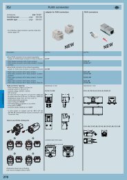
CX 01 JF/M RJ45 + auxiliary electric crimp 10 250 2<br />
CX 02 JF/M RJ45 + auxiliary electric crimp 10 250 3<br />
CX 01 UF/M USB electric --- --- --- 1<br />
CX 01 9VF/M D-SUB electric crimp 5 50 1<br />
CX 04 LF/M POF / MOST / coaxial optic / electric crimp / solder --- --- 1<br />
** Warning: For obvious reasons of safety, the VDE standard does not permit electric contacts to be present within the same connector group together with contacts for the<br />
transmission of liquids. In addition, the use of pneumatic air contacts requires an appropriate filtering and dehydration system to prevent dangerous condensation.<br />
Contacts may be used for pressure values of up to a maximum of 8 bar/116 psi.<br />
158
main features<br />
<strong>MIXO</strong> CX..Y 200A version modular inserts.<br />
The <strong>MIXO</strong> series has been enhanced with a new insert, suitable for currents up to 200A and with new, CY series crimp contacts featuring several<br />
benefits over conventional screw or axial screw contacts:<br />
• More resistant to mechanical stresses such as vibrations, shock and cable loads<br />
• More corrosion resistant (gas tight)<br />
• Quicker to connect and ensuring more consistent results (regardless of the operators “force”)<br />
• The connector is electrically more efficient (reduced voltage drop)<br />
This innovative insert design following the same concepts of the <strong>MIXO</strong> 100A CX..G model, patented by ILME, ensures a quicker fitting and removal of<br />
crimped contacts.<br />
The four provided keys firmly fasten the contact holder and; once the insert is joined to other inserts (and it is installed in the correspondind <strong>MIXO</strong> frame)<br />
the connection is totally secure and extremely resistant, even under the most severe stresses such as vibration and shock.<br />
The contacts can be removed without any special tool, using a simple screwdriver.<br />
The crimping operation can be carried out quickly and efficiently with the CYPZ hand operated hydraulic pliers, which is pre-fitted with the suitable locator.<br />
Suitable crimp dies available on request.<br />
<strong>MIXO</strong><br />
code inserts (<strong>MIXO</strong> series)<br />
No. of poles<br />
rated current 1)<br />
CX..Y<br />
main contact 1<br />
auxiliary contacts --<br />
200A<br />
1) Please check the insert load curves to establish the<br />
actual maximum operating current according to the<br />
ambient temperature.<br />
2) Certifications shown in brackets are currently being<br />
applied for.<br />
rated voltage<br />
1000V<br />
EN 61984 rated impulse 8kV<br />
pollution degree 3<br />
withstand voltage<br />
pollution degree 3<br />
UL/CSA certification rated voltage (a.c../d.c.) 600V<br />
certifications 2)<br />
contact resistance<br />
insulation resistance<br />
(cUL), (CSA), (CCC), (GL)<br />
≤ 0.2 mΩ<br />
≥ 10 GΩ<br />
ambient temperature limit min -40<br />
(°C) max +125<br />
degree of protection with enclosures (according to version) IP65, IP66, IP67, IP68, IP69K<br />
without enclosures<br />
IP20<br />
conductor connections *<br />
crimp<br />
mm 2 16, 25, 35, 50, 70<br />
conductor cross-section<br />
AWG 6, 4, 2, 1, 2/0<br />
stripping lenght mm 15<br />
mechanical endurance (rating cycles)<br />
≥500<br />
* max external conductor Ø = 16 mm<br />
<br />
159
<strong>MIXO</strong> modular units 1 pole 200A - 1000V<br />
the modular inserts must be installed in suitable<br />
frames which are then mounted in traditional<br />
housings * or COB panel support<br />
modular units,<br />
crimp connections<br />
200A silver plated crimp contacts<br />
heat shrink tube<br />
frames for modular units * ............ page: 195<br />
* enclosures: housings or high construction hoods<br />
<strong>MIXO</strong><br />
NEW<br />
description part No. part No.<br />
without contacts (to be ordered separately)<br />
- female inserts for female contacts CX 01 YF<br />
- male inserts for female contacts CX 01 YM<br />
200A female crimp contacts<br />
16 mm 2 AWG 6 one groove (back side) CYFA 16<br />
25 mm 2 AWG 4 with no grooves CYFA 25<br />
35 mm 2 AWG 2 one groove CYFA 35<br />
50 mm 2 AWG 1 two grooves CYFA 50<br />
70 mm 2 AWG 2/0 with no grooves CYFA 70<br />
200A male crimp contacts<br />
16 mm 2 AWG 6 one groove (back side) CYMA 16<br />
25 mm 2 AWG 4 with no grooves CYMA 25<br />
35 mm 2 AWG 2 one groove CYMA 35<br />
50 mm 2 AWG 1 two grooves CYMA 50<br />
70 mm 2 AWG 2/0 with no grooves CYMA 70<br />
heat shrink tube for CYFA/CYMA 16 contacts or for<br />
conductor with total external Ø < 10 mm<br />
CR TT<br />
silver plated<br />
- characteristics according to EN 61984:<br />
200A 1000V 8kV 3<br />
200A 920/1600V 8kV 2<br />
- certifications: (cUL - UL for USA and Canada),<br />
(CSA), (CCC), (GL); the certifications shown in<br />
brackets are being applied for<br />
- rated voltage according to UL/CSA: 600V<br />
- insulation resistance: ≥ 10 GΩ<br />
- ambient temperature limit: -40 °C ... +125 °C<br />
- are made of self-extinguishing thermoplastic resin UL 94 V0<br />
- mechanical life: ≥ 500 cycles<br />
- contact resistance: ≤ 0,2 mΩ<br />
- for maximum current load, see the following load<br />
curves inserts, for more information see page 499<br />
dimensions in mm<br />
34 29.4<br />
52.3<br />
M<br />
F<br />
dimensions in mm<br />
CYF and CYM<br />
ø A<br />
40<br />
ø 20<br />
ø 9.5<br />
ø 20<br />
38<br />
CYF and CYM contacts<br />
conductor conductor conductor<br />
section slot stripping<br />
ø A lenght<br />
(mm 2 ) (mm) (mm)<br />
16 6.1 15<br />
25 7.0 15<br />
35 8.2 15<br />
50 9.8 15<br />
70 11.8 15<br />
diagramme CX 01 Y - 1 pôle (<strong>MIXO</strong> 200A)<br />
200<br />
190<br />
180<br />
50 mm 2 70 mm 2<br />
57.8<br />
ø A<br />
170<br />
160<br />
CR TT<br />
150<br />
courant d’exercice (A)<br />
140<br />
130<br />
120<br />
110<br />
100<br />
90<br />
80<br />
70<br />
60<br />
50<br />
25 mm 2 35 mm 2<br />
contacts side (front view)<br />
side with reference arrow ▲<br />
F<br />
M<br />
heat shrink tube<br />
40<br />
30<br />
20<br />
10<br />
0<br />
0 10 20 30 40 50 60 70 80 90 100 110 120 130<br />
température ambiante (°C)<br />
dimensions shown are not binding<br />
and may be changed without notice<br />
- 2 frame slots<br />
YES<br />
90/100 °C<br />
NO<br />
160
<strong>MIXO</strong> modular units 1 PE pole 200A<br />
the modular inserts must be installed in suitable<br />
frames which are then mounted in traditional<br />
housings * or COB panel support<br />
modular units,<br />
crimp connections<br />
PE module for earth termination<br />
200A silver plated crimp contacts<br />
frames for modular units * ............ page: 195<br />
* enclosures: housings or high construction hoods<br />
NEW<br />
<strong>MIXO</strong><br />
description part No. part No.<br />
without contacts (to be ordered separately)<br />
- PE female inserts for female contacts CX 01 YPEF<br />
- PE male inserts for female contacts CX 01 YPEM<br />
200A female crimp contacts<br />
16 mm 2 AWG 6 one groove (back side) CYFA 16<br />
25 mm 2 AWG 4 with no grooves CYFA 25<br />
35 mm 2 AWG 2 one groove CYFA 35<br />
50 mm 2 AWG 1 two grooves CYFA 50<br />
70 mm 2 AWG 2/0 with no grooves CYFA 70<br />
200A male crimp contacts<br />
16 mm 2 AWG 6 one groove (back side) CYMA 16<br />
25 mm 2 AWG 4 with no grooves CYMA 25<br />
35 mm 2 AWG 2 one groove CYMA 35<br />
50 mm 2 AWG 1 two grooves CYMA 50<br />
70 mm 2 AWG 2/0 with no grooves CYMA 70<br />
silver plated<br />
- certifications: (cUL - UL for USA and Canada),<br />
(CSA), (CCC), (GL); the certifications shown in<br />
brackets are being applied for<br />
- ambient temperature limit: -40 °C ... +125 °C<br />
- are made of self-extinguishing thermoplastic resin<br />
UL 94 V0<br />
dimensions in mm<br />
34 29.4<br />
M<br />
dimensions in mm<br />
CYF and CYM<br />
ø A<br />
42<br />
40<br />
ø 20<br />
CX 01 YPE<br />
ø 9.5<br />
F<br />
ø 20<br />
38<br />
49<br />
ø A<br />
1 2 3 contacts side (front view) 4<br />
side with reference arrow ▲<br />
F<br />
3 4<br />
M<br />
CYF and CYM contacts<br />
conductor conductor slot conductor<br />
section ø A stripping lenght<br />
(mm 2 ) (mm) (mm)<br />
16 6.1 15<br />
25 7.0 15<br />
35 8.2 15<br />
50 9.8 15<br />
70 11.8 15<br />
- 2 frame slots<br />
dimensions shown are not binding<br />
and may be changed without notice<br />
161
main features<br />
<strong>MIXO</strong> CX..G 100A version modular inserts.<br />
The <strong>MIXO</strong> series has been enhanced with a new insert, suitable for currents up to 100A and with new, CG series crimp contacts featuring several<br />
benefits over conventional screw contacts as they are:<br />
• More resistant to mechanical stresses such as vibrations and cable loads<br />
• More corrosion resistant (gas tight)<br />
• Quicker to connect and ensuring more consistent results (regardless of the operators “force”)<br />
• The connector is electrically more efficient (reduced voltage drop)<br />
This innovative insert design, patented by ILME, ensures a quicker fitting and removal of crimped contacts.<br />
<strong>MIXO</strong><br />
The plates provided firmly fasten the contact holder and, once the insert is mated to other inserts and is inserted in the <strong>MIXO</strong> frame, the connection is totally<br />
secure and extremely resistant, even to the most severe stresses such as vibrations.<br />
The contacts can be removed without having to use any special tools but by simply using a screwdriver.<br />
The crimping operation can be carried out quickly and effectively thanks to the CGPZ hydraulically operated pliers provided which, on request, can be<br />
supplied with the required locator and dies.<br />
<br />
162
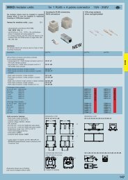
<strong>MIXO</strong> modular units 2 poles 100A - 1000V<br />
the modular inserts must be installed in suitable<br />
frames which in turn are installed in traditional<br />
housings * or COB panel support<br />
modular units,<br />
crimp connections<br />
100A silver plated crimp contacts,<br />
PE adapter<br />
frames for modular units * ............ page: 195<br />
* enclosures: bulkhead mounting housings, high<br />
construction housings or high construction hoods<br />
<strong>MIXO</strong><br />
description part No. part No.<br />
without contacts (to be ordered separately)<br />
- female inserts for female contacts ** CX 02 GF<br />
- male inserts for female contacts ** CX 02 GM<br />
100A female crimp contacts<br />
16 mm 2 AWG 6 - 5 CGFA 16<br />
25 mm 2 AWG 4 - 3 CGFA 25<br />
35 mm 2 AWG 2 CGFA 35<br />
100A male crimp contacts<br />
16 mm 2 AWG 6 - 5 CGMA 16<br />
25 mm 2 AWG 4 - 3 CGMA 25<br />
35 mm 2 AWG 2 CGMA 35<br />
silver plated<br />
cable earthing adapter 16 mm 2 (AWG 6 - 5) CGT 16<br />
** on request, version with pole 3/4 numbering,<br />
references: CX 02 GFN, CX 02 GMN<br />
dimensions in mm<br />
34 29.4<br />
dimensions in mm<br />
CGF and CGM CGT 16<br />
ø A<br />
ø 5.5<br />
- characteristics according to EN 61984:<br />
100A 1000V 8kV 3<br />
100A 920/1600V 8kV 2<br />
- certifications: cUL (UL for USA and Canada), CCC,<br />
GL, GOST<br />
- rated voltage according to UL/CSA: 600V<br />
- insulation resistance: ≥ 10 GΩ<br />
- ambient temperature limit: -40 °C ... +125 °C<br />
- are made of self-extinguishing thermoplastic resin UL<br />
94 V0<br />
- mechanical life: ≥ 500 cycles<br />
- contact resistance: ≤ 0.3 mΩ<br />
- for contact crimping instructions, please see the<br />
crimping tool section (100A contacts, CGF and CGM<br />
series) on page 476<br />
- for maximum current load, see the following load<br />
curves inserts, for more information see page 499<br />
49<br />
51<br />
M<br />
F<br />
15.5<br />
ø C<br />
ø 8<br />
37<br />
39.5<br />
8<br />
ø 4.6<br />
15<br />
26<br />
15.5<br />
working current (A)<br />
140<br />
120<br />
100<br />
80<br />
60<br />
40<br />
diagram CX 02 poles (<strong>MIXO</strong> 100A)<br />
contacts side (front view)<br />
side with reference arrow ▲<br />
F<br />
M<br />
ø C<br />
ø B<br />
CGF and CGM contacts<br />
conductor conductor slot conductor<br />
section ø A ø B ø C stripping lenght<br />
(mm 2 ) (mm) (mm) (mm) (mm)<br />
16 5.5 5.5 13 15<br />
25 7.0 7.0 13 15<br />
35 7.9 8.2 12.5 15<br />
20<br />
0<br />
0 10 20 30 40 50 60 70 80 90 100 110 120 130<br />
ambient temperature (°C)<br />
dimensions shown are not binding<br />
and may be changed without notice<br />
- footprint 2 modules<br />
How to use the PE adapter (CGT 16):<br />
1) Strip 15 mm of flexible PE protective cable<br />
2) Crimp the cable on the CGT 16 adapter by using the<br />
CGPZ pliers with the CGD 16 C matrix<br />
3) Fix the adapter tip in the larger earth terminal<br />
(6 mm 2 ) of frames CX...TM/TF<br />
4) To be used with bulkhead mounting housings or<br />
high construction hoods<br />
5) Cannot be used with T-TYPE series<br />
163
<strong>MIXO</strong> modular units 2 poles 70A - 1000V<br />
the modular inserts must be installed in suitable<br />
frames which in turn are installed in traditional<br />
housings * or COB panel support<br />
modular units,<br />
crimp connections<br />
70A silver plated crimp contacts<br />
frames for modular units * .... page: 194 - 195<br />
* enclosures: bulkhead mounting housings, high<br />
construction housings or high construction hoods<br />
<strong>MIXO</strong><br />
NEW<br />
description part No. part No.<br />
NEW<br />
without contacts (to be ordered separately)<br />
- female inserts for female contacts CX 02 7F<br />
- male inserts for female contacts CX 02 7M<br />
70A female crimp contacts<br />
10 mm 2 AWG 8 - 7 CX7FA 10<br />
16 mm 2 AWG 6 - 5 CX7FA 16<br />
25 mm 2 AWG 4 - 3 CX7FA 25<br />
70A male crimp contacts<br />
10 mm 2 AWG 8 - 7 CX7MA 10<br />
16 mm 2 AWG 6 - 5 CX7MA 16<br />
25 mm 2 AWG 4 - 3 CX7MA 25<br />
- characteristics according to EN 61984:<br />
70A 1000V 8kV 3<br />
70A 1600V 12kV 2<br />
- insulation resistance: ≥ 10 GΩ<br />
- ambient temperature limit: -40 °C ... +125 °C<br />
- are made of self-extinguishing thermoplastic resin UL<br />
94 V0<br />
- mechanical life: ≥ 500 cycles<br />
- for contact crimping instructions, please see the<br />
crimping tool section (70A contacts, CX7F and CX7M<br />
series) on page 474<br />
- C7ES removal tool<br />
dimensions in mm<br />
34 14.7<br />
49.5<br />
M<br />
dimensions in mm<br />
ø 11.5<br />
ø A<br />
15.5<br />
silver plated<br />
35.5<br />
ø 6<br />
F<br />
32.5<br />
51<br />
15.5<br />
ø A<br />
ø 11.5<br />
contacts side (front view)<br />
side with reference arrow ▲<br />
F<br />
M<br />
contacts CX7F and CX7M<br />
conductor conductor slot conductor<br />
section ø A stripping lenght<br />
(mm 2 ) (mm) (mm)<br />
10 4.3 15<br />
16 5.5 15<br />
25 7.0 15<br />
- footprint 1 module<br />
dimensions shown are not binding<br />
and may be changed without notice<br />
164
<strong>MIXO</strong> modular units 2 poles 40A - 1000V<br />
the modular inserts must be installed in suitable<br />
frames which in turn are installed in traditional<br />
housings or COB panel support<br />
modular units,<br />
modular units,<br />
screw terminal connection<br />
screw terminal connection<br />
2.5 ÷ 8 mm 2 6 ÷ 10 mm 2<br />
frames for modular units ....... page: 194 - 195<br />
- characteristics according to EN 61984:<br />
40A 1000V 8kV 3<br />
40A 1600V 12kV 2<br />
- UL, CSA, GOST certified<br />
- rated voltage according to UL/CSA: 600V<br />
- insulation resistance: ≥ 10 GΩ<br />
- ambient temperature limit: -40 °C ... +125 °C<br />
- are made of self-extinguishing thermoplastic resin UL 94 V0<br />
- mechanical life: ≥ 500 cycles<br />
- contact resistance: ≤ 0.5 mΩ<br />
<strong>MIXO</strong><br />
description part No. part No.<br />
- female inserts with female contacts CX 02 4AF<br />
- male inserts with female contacts CX 02 4AM<br />
- female inserts with female contacts CX 02 4BF<br />
- male inserts with female contacts CX 02 4BM<br />
- for maximum current load, see the following<br />
load curves inserts, for more information<br />
see page 500<br />
diagramme CX 02 4A/B pôles<br />
70<br />
dimensions in mm<br />
34 14.7<br />
M<br />
dimensions in mm<br />
34 14.7<br />
M<br />
60<br />
courant d’exercice (A)<br />
50<br />
40<br />
30<br />
20<br />
39.5<br />
F<br />
39.5<br />
F<br />
10<br />
40<br />
40<br />
0<br />
0 10 20 30 40 50 60 70 80 90 100 110 120 130<br />
température ambiante (°C)<br />
● use flexible cables with sections from 2.5 to 10 mm 2<br />
or extra flexible cables with sections from<br />
2.5 to 6 mm 2<br />
● do not twist the cables<br />
● fully insert the braids in the rear section of the contact<br />
contacts side (front view)<br />
side with reference arrow ▲<br />
F<br />
M<br />
contacts side (front view)<br />
side with reference arrow ▲<br />
F<br />
M<br />
conductor conductor tightening<br />
section stripping lenght torque<br />
(mm 2 ) (mm) (Nm)<br />
2.5 5 +1 1.5<br />
4 5 +1 1.5<br />
6 8 +1 2<br />
10 8 +1 2<br />
● insert a 2 mm hexagonal key in the front section of<br />
the contact and tighten by keeping the cable held<br />
down in position<br />
● a 2 mm hexagonal key can be supplied on request,<br />
reference CX AS<br />
- inserts for Ø 4mm cables, section:<br />
2.5-8 mm 2 - AWG 14-8<br />
- footprint 1 module<br />
- inserts for Ø 4.8 mm cables, section:<br />
6-10 mm 2 - AWG 10-8<br />
- footprint 1 module<br />
dimensions shown are not binding and may be changed without notice<br />
165
main features<br />
<strong>MIXO</strong> CX 3/4 XD modular connectors<br />
<strong>MIXO</strong><br />
CX 3/4 XD connectors have the following characteristics:<br />
- 3 slots for CX crimped contacts (40A max) for power circuits<br />
- 4 slots for CD crimped contacts (10A max) for signal circuits<br />
Their key characteristic lies in the fact that they guarantee maximum safety even in case of accidental contact with fingers (IPXXB or IP2X).<br />
Safety is guaranteed as standard on female contacts, but also on male contacts. This feature is important as it ensures full compliance with the recent<br />
safety standard EN 60204-1, concerning electric equipment fitted on machines and in particular with the requirements of Article 6.2.4 concerning<br />
protection against residual voltage.<br />
Live parts having a residual voltage greater than 60V after the supply has been disconnected shall be discharged to 60V or less within a time period of<br />
5 s after disconnection of the supply voltage provided that this rate of discharge does not interfere with the proper functioning of the equipment. Exempted<br />
from this requirement are components having a stored charge of 60 µC or less. Where this specified rate of discharge would interfere with the proper<br />
functioning of the equipment, a durable warning notice drawing attention to the hazard and stating the delay required before the enclosure may be opened<br />
shall be displayed at an easily visible location on or immediately adjacent to the enclosure containing the capacitances.<br />
In the case of plugs or similar devices, the withdrawal of which results in the exposure of conductors (for example pins), the discharge time shall<br />
not exceed 1 s, otherwise such conductors shall be protected against direct contact to at least an IP2X or IPXXB. If neither a discharge time of<br />
1 s nor a protection of at least IP2X or IPXXB can be achieved (for example in the case of removable collectors on conductor wires, conductors bars, or<br />
slip-ring assemblies, see 12.7.4), additional switching devices or an appropriate warning device (for example a warning notice in accordance with 16.1)<br />
shall be applied.<br />
The IP2X or IPXXB protection offered by CX 3/4 XDM modules fitted with CX and CD contacts ensures greater design flexibility as it enables, for<br />
example, connectors to be used for drives of electric motors (frequency converters) and in all applications where voltage could be present on both sides<br />
of the connector (for example power circuits in loop configuration, opening, circuits of battery-chargers).<br />
Thanks to the enhanced insulation, the rated voltage of the module is equivalent to 830V, in compliance with standards EN 61984 and EN 60664-1, with<br />
an impulse withstand voltage of 8 kV for pollution degree 3 even between signal contacts.<br />
code inserts (<strong>MIXO</strong> series)<br />
No. of poles<br />
main contacts 3<br />
auxiliary contacts 4<br />
CX..XD<br />
1) Please check the insert load curves to establish the<br />
actual maximum operating current according to the<br />
ambient temperature.<br />
2) Certifications shown in brackets are currently being<br />
applied for.<br />
rated current 1) main contacts 40A<br />
auxiliary contacts<br />
10A<br />
rated voltage<br />
830V<br />
EN 61984 rated impulse 8kV<br />
pollution degree 3<br />
withstand voltage<br />
pollution degree 3<br />
UL/CSA certification rated voltage (a.c../d.c.) 600V<br />
certifications 2)<br />
(cUL), (CSA), (CCC), (GL)<br />
contact resistance<br />
insulation resistance<br />
main contacts<br />
auxiliary contacts<br />
≤ 0.3 mΩ<br />
≤ 3 mΩ<br />
≥ 10 GΩ<br />
ambient temperature limit min -40<br />
(°C) max +125<br />
degree of protection with enclosures IP65, IP66, IP67, IP68, IP69K<br />
(according to type)<br />
without enclosures<br />
IP20, also on male contacts<br />
conductor connections<br />
conductor cross-section<br />
main contacts<br />
conductor cross-section<br />
auxiliary contacts<br />
crimp<br />
mm 2 1.5÷6<br />
AWG 16÷10<br />
mm 2 0.14÷2.5<br />
AWG 26÷14<br />
stripping lenght mm 9 (1.5÷2.5 mm 2 )<br />
main contacts 9.6 (4÷6 mm 2 )<br />
stripping lenght mm 8 (0.14÷1.5 mm 2 )<br />
auxiliary contacts 6 (2.5 mm 2 )<br />
mechanical endurance (rating cycles)<br />
≥500<br />
166
<strong>MIXO</strong> modular units 3 poles (40A - 830V) + 4 poles (10A - 830V)<br />
the modular inserts must be installed in suitable<br />
frames which are then mounted in traditional<br />
housings or COB panel support<br />
frames for modular units ....... page: 194 - 195<br />
modular units,<br />
crimp connections<br />
40A and 10A crimp contacts<br />
silver and gold plated<br />
40A<br />
- male and female contacts to test of contact with fingers<br />
- for contact crimping, see the crimp tool section (40A<br />
contacts CXF, CXM series and 10A contacts CDF,<br />
CDM series) on pages 466, 468, 470, 480, 482, 484,<br />
486<br />
NEW<br />
10A<br />
<strong>MIXO</strong><br />
description part No. part No. part No.<br />
without contacts (to be ordered separately)<br />
- female inserts for female contacts CX 3/4 XDF<br />
- male inserts for male contacts CX 3/4 XDM<br />
40A female crimp contacts<br />
1.5 mm 2 AWG 16 CXFA 1.5<br />
2.5 mm 2 AWG 14 CXFA 2.5<br />
4 mm 2 AWG 12 CXFA 4.0<br />
6 mm 2 AWG 10 CXFA 6.0<br />
40A male crimp contacts<br />
1.5 mm 2 AWG 16 CXMA 1.5<br />
2.5 mm 2 AWG 14 CXMA 2.5<br />
4 mm 2 AWG 12 CXMA 4.0<br />
6 mm 2 AWG 10 CXMA 6.0<br />
10A female contacts<br />
0.14-0.37 mm 2 AWG 26-22 identification No. 1 CDFA 0.3 CDFD 0.3<br />
0.5 mm 2 AWG 20 identification No. 2 CDFA 0.5 CDFD 0.5<br />
0.75 mm 2 AWG 18 identification No. CDFA 0.7 CDFD 0.7<br />
1 mm 2 AWG 18 identification No. 3 CDFA 1.0 CDFD 1.0<br />
1.5 mm 2 AWG 16 identification No. 4 CDFA 1.5 CDFD 1.5<br />
2.5 mm 2 AWG 14 identification No. 5 CDFA 2.5 CDFD 2.5<br />
10A male contacts<br />
0.14-0.37 mm 2 AWG 26-22 identification No. 1 CDMA 0.3 CDMD 0.3<br />
0.5 mm 2 AWG 20 identification No. 2 CDMA 0.5 CDMD 0.5<br />
0.75 mm 2 AWG 18 identification No. CDMA 0.7 CDMD 0.7<br />
1 mm 2 AWG 18 identification No. 3 CDMA 1.0 CDMD 1.0<br />
1.5 mm 2 AWG 16 identification No. 4 CDMA 1.5 CDMD 1.5<br />
2.5 mm 2 AWG 14 identification No. 5 CDMA 2.5 CDMD 2.5<br />
- characteristics according to EN 61984:<br />
3 poles 40A 830V 8kV 3<br />
4 poles 10A 830V 8kV 3<br />
- certifications: (cUL - UL for USA and Canada),<br />
(CSA), (CCC), (GL); the certifications shown in<br />
brackets are being applied for<br />
- rated voltage according to UL/CSA: 600V<br />
- insulation resistance: ≥ 10 GΩ<br />
- ambient temperature limit: -40 °C ... +125 °C<br />
- are made of self-extinguishing thermoplastic resin<br />
UL 94 V0<br />
- mechanical life: ≥ 500 cycles<br />
- contact resistance: ≤ 0.3 mΩ (3 poles)<br />
≤ 3 mΩ (4 poles)<br />
- for maximum current load, see the following load<br />
curves inserts, for more information see page 500<br />
working current (A)<br />
diagram CX 3/4 poles<br />
50<br />
40<br />
35<br />
30<br />
25<br />
20<br />
15<br />
10<br />
5<br />
4,0 mm 2 6,0 mm 2<br />
0<br />
0 10 20 30 40 50 60 70 80 90 100 110 120 130<br />
ambient temperature (°C)<br />
dimensions in mm<br />
contacts side (front view)<br />
- 1 frame slot<br />
11<br />
13<br />
dimensions shown are not binding and may be changed without notice<br />
12<br />
34 14.7<br />
side with reference arrow ▲<br />
11<br />
12<br />
14<br />
1<br />
13<br />
2<br />
14<br />
3<br />
F<br />
1<br />
2<br />
3<br />
13<br />
13<br />
11<br />
14 12<br />
11<br />
14 12<br />
M<br />
44.3<br />
39<br />
M<br />
F<br />
CXF and CXM<br />
ø A<br />
ø 6<br />
B<br />
29<br />
ø 4<br />
B<br />
23.5<br />
ø 6<br />
ø A<br />
silver plated<br />
silver plated<br />
dimensions in mm<br />
ø 3.5<br />
CDF and CDM<br />
B<br />
ø A<br />
ø 3.2<br />
25<br />
ø 1.6<br />
B<br />
21.6<br />
ø A<br />
gold plated<br />
CDF and CDM contacts<br />
conductor conductor conductors<br />
section<br />
mm 2 slot<br />
ø A (mm)<br />
stripping length<br />
B (mm)<br />
0.14÷0.37 0.9 8<br />
0.5 1.1 8<br />
0.75 1.3 8<br />
1.0 1.45 8<br />
1.5<br />
2.5<br />
1.8<br />
2.2<br />
8<br />
6<br />
CXF and CXM contacts<br />
conductor conductor conductors<br />
section<br />
mm 2 slot<br />
ø A (mm)<br />
stripping length<br />
B (mm)<br />
1.5 1.8 9<br />
2.5 2.2 9<br />
4<br />
6<br />
2.85<br />
3.5<br />
9.6<br />
9.6<br />
167
<strong>MIXO</strong> modular units 3 poles 40A - 400/690V<br />
the modular inserts must be installed in suitable<br />
frames which in turn are installed in traditional<br />
housings or COB panel support<br />
modular units,<br />
crimp connections<br />
40A crimp contacts<br />
silver plated<br />
frames for modular units ....... page: 194 - 195<br />
<strong>MIXO</strong><br />
description part No. part No.<br />
without contacts (to be ordered separately)<br />
- female inserts for female contacts CX 03 4F *<br />
- male inserts for male contacts CX 03 4M *<br />
40A female crimp contacts<br />
1.5 mm 2 AWG 16 CXFA 1.5<br />
2.5 mm 2 AWG 14 CXFA 2.5<br />
4 mm 2 AWG 12 CXFA 4.0<br />
6 mm 2 AWG 10 CXFA 6.0<br />
40A male crimp contacts<br />
1.5 mm 2 AWG 16 CXMA 1.5<br />
2.5 mm 2 AWG 14 CXMA 2.5<br />
4 mm 2 AWG 12 CXMA 4.0<br />
6 mm 2 AWG 10 CXMA 6.0<br />
silver plated<br />
* cable diameter up to 5 mm dimensions in mm dimensions in mm<br />
- characteristics according to EN 61984:<br />
40A 400/690V 6kV 3<br />
- UL, CSA, GOST certified<br />
- rated voltage according to UL/CSA: 600V<br />
- insulation resistance: ≥ 10 GΩ<br />
- ambient temperature limit: -40 °C ... +125 °C<br />
- are made of self-extinguishing thermoplastic resin<br />
UL 94 V0<br />
- mechanical life: ≥ 500 cycles<br />
- contact resistance: ≤ 0.3 mΩ<br />
- for contact crimping instructions, please see the<br />
crimping tool section (40A contacts, CXF and CXM<br />
series) on pages 468, 470 and 486<br />
- for maximum current load, see the following load<br />
curves inserts, for more information see page 500<br />
34 14.7<br />
M<br />
39.5<br />
F<br />
40<br />
ø A<br />
ø 6<br />
B<br />
29.1<br />
ø 4<br />
23.5<br />
diagram CX 03 poles<br />
50<br />
B<br />
ø 6<br />
40<br />
ø A<br />
working current (A)<br />
35<br />
30<br />
25<br />
20<br />
15<br />
10<br />
5<br />
2,5 mm 2 4,0 mm 2 6,0 mm 2<br />
contacts side (front view)<br />
side with reference arrow ▲<br />
1<br />
F<br />
2<br />
3<br />
1<br />
1<br />
M<br />
3<br />
1<br />
2<br />
CXF and CXM contacts<br />
conductor conductor conductors<br />
section slot stripping length<br />
mm 2 ø A (mm) B (mm)<br />
1.5 1.8 9<br />
2.5 2.2 9<br />
4 2.85 9.6<br />
6 3.5 9.6<br />
0<br />
0 10 20 30 40 50 60 70 80 90 100 110 120 130<br />
ambient temperature (°C)<br />
3<br />
2<br />
3<br />
2<br />
- footprint 1 module<br />
dimensions shown are not binding<br />
and may be changed without notice<br />
168
<strong>MIXO</strong> modular units 3 poles 40A - 500V<br />
the modular inserts must be installed in suitable<br />
frames which in turn are installed in traditional<br />
housings or COB panel support<br />
modular units,<br />
crimp connections<br />
40A crimp contacts<br />
silver plated<br />
frames for modular units ....... page: 194 - 195<br />
NEW<br />
description part No. part No.<br />
<strong>MIXO</strong><br />
without contacts (to be ordered separately)<br />
- female inserts for female contacts CX 03 4BF *<br />
- male inserts for male contacts CX 03 4BM *<br />
40A female crimp contacts<br />
1.5 mm 2 AWG 16 CXFA 1.5<br />
2.5 mm 2 AWG 14 CXFA 2.5<br />
4 mm 2 AWG 12 CXFA 4.0<br />
6 mm 2 AWG 10 CXFA 6.0<br />
10 mm 2 AWG 8 CXFA 10<br />
40A male crimp contacts<br />
1.5 mm 2 AWG 16 CXMA 1.5<br />
2.5 mm 2 AWG 14 CXMA 2.5<br />
4 mm 2 AWG 12 CXMA 4.0<br />
6 mm 2 AWG 10 CXMA 6.0<br />
10 mm 2 AWG 8 CXMA 10<br />
silver plated<br />
* cable diameter up to 7.5 mm<br />
contact section up to 10 mm 2<br />
dimensions in mm<br />
34 14.7<br />
dimensions in mm<br />
ø A<br />
ø 6<br />
- characteristics according to EN 61984:<br />
40A 500V 6kV 3<br />
- certifications: (UL), (CSA), (GOST); the certifications<br />
shown in brackets are being applied for<br />
- insulation resistance: ≥ 10 GΩ<br />
- ambient temperature limit: -40 °C ... +125 °C<br />
- are made of self-extinguishing thermoplastic resin<br />
UL 94 V0<br />
- mechanical life: ≥ 500 cycles<br />
- contact resistance: ≤ 0.3 mΩ<br />
- for contact crimping instructions (1.5 ÷ 10 mm 2 ),<br />
please see the crimping tool section (40A contacts,<br />
CXF and CXM series) on pages 468, 470 and 486<br />
- for maximum current load, see the following load<br />
curves inserts, for more information see page 500<br />
M<br />
43.5<br />
F<br />
44<br />
B<br />
29.1<br />
ø 4<br />
23.5<br />
B<br />
ø 6<br />
diagram CX 03 4B poles<br />
50<br />
ø A<br />
working current (A)<br />
40<br />
35<br />
30<br />
25<br />
20<br />
15<br />
2,5 mm 2<br />
4,0 mm 2 6,0 mm 2 10 mm 2<br />
contacts side (front view)<br />
side with reference arrow ▲<br />
1<br />
F<br />
2<br />
3<br />
1<br />
1<br />
2<br />
2<br />
3<br />
3<br />
M<br />
3<br />
1<br />
2<br />
CXF and CXM contacts<br />
conductor conductor conductors<br />
section slot stripping length<br />
mm 2 ø A (mm) B (mm)<br />
1.5 1.8 9<br />
2.5 2.2 9<br />
4 2.85 9.6<br />
6 3.5 9.6<br />
10 4.3 15<br />
10<br />
5<br />
0<br />
0 10 20 30 40 50 60 70 80 90 100 110 120 130<br />
ambient temperature (°C)<br />
- footprint 1 module<br />
dimensions shown are not binding<br />
and may be changed without notice<br />
169
main features<br />
<strong>MIXO</strong> CX 4 X modular connectors<br />
The new CX 04 X inserts have the same dimensions of CX 03 4F/M inserts, but have 4 seats for crimp contacts series CX (40A max) used in power circuits.<br />
Thanks to the enhanced insulation, the rated voltage of the module is equivalent to 830V, in compliance with standards EN 61984 and EN 60664-1, with<br />
an impulse withstand voltage of 8 kV for pollution degree 3 even between signal contacts..<br />
Their key characteristic lies in the fact that they guarantee maximum safety even in case of accidental contact with fingers (IPXXB or IP2X).<br />
Safety is guaranteed as standard on female contacts, but also on male contacts.<br />
This feature is important as it ensures full compliance with the recent safety standard EN 60204-1, concerning electric equipment fitted on machines and<br />
in particular with the requirements of Article 6.2.4 concerning protection against residual voltage:<br />
<strong>MIXO</strong><br />
Live parts having a residual voltage greater than 60V after the supply has been disconnected shall be discharged to 60V or less within a time period of<br />
5 s after disconnection of the supply voltage provided that this rate of discharge does not interfere with the proper functioning of the equipment.<br />
Exempted from this requirement are components having a stored charge of 60 µC or less.<br />
Where this specified rate of discharge would interfere with the proper functioning of the equipment, a durable warning notice drawing attention to the<br />
hazard and stating the delay required before the enclosure may be opened shall be displayed at an easily visible location on or immediately adjacent to<br />
the enclosure containing the capacitances.<br />
In the case of plugs or similar devices, the withdrawal of which results in the exposure of conductors (for example pins), the discharge time shall<br />
not exceed 1 s, otherwise such conductors shall be protected against direct contact to at least an IP2X or IPXXB. If neither a discharge time of<br />
1 s nor a protection of at least IP2X or IPXXB can be achieved (for example in the case of removable collectors on conductor wires, conductors bars, or<br />
slip-ring assemblies, see 12.7.4), additional switching devices or an appropriate warning device (for example a warning notice in accordance with 16.1)<br />
shall be applied.<br />
The IP2X or IPXXB protection offered by CX 04 XM modules fitted with CX contacts ensures greater design flexibility as it enables, for example, connectors to<br />
be used for drives of electric motors (frequency converters) and in all applications where voltage could be present on both sides of the connector (for<br />
example power circuits in loop configuration, opening, circuits of battery-chargers).<br />
NOTE<br />
Female inserts are supplied with two red lock tabs that must be used to assemble the inserts on the frame instead of the grey ones supplied with the frame.<br />
code inserts (<strong>MIXO</strong> series)<br />
No. of poles main contacts 4<br />
CX..X<br />
1) Please check the insert load curves to establish the<br />
actual maximum operating current according to the<br />
ambient temperature.<br />
2) Certifications shown in brackets are currently being<br />
applied for.<br />
rated current 1)<br />
40A<br />
rated voltage<br />
830V<br />
EN 61984 rated impulse 8kV<br />
pollution degree 3<br />
withstand voltage<br />
pollution degree 3<br />
UL/CSA certification rated voltage (a.c../d.c.) 600V<br />
certifications 2)<br />
(cUL), (CSA), (CCC), (GL)<br />
contact resistance<br />
insulated resistance<br />
≤ 0,3 mΩ<br />
≥ 10 GΩ<br />
ambient temperature min -40<br />
limit (°C) max +125<br />
degree of protection with enclosures IP65, IP66, IP67, IP68, IP69K<br />
(according to type)<br />
conductor connections<br />
without enclosures<br />
conductor cross-section mm 2 1.5÷6<br />
main contacts<br />
IP20 also on male contacts<br />
crimp<br />
stripping lenght mm 9 (1.5÷2.5 mm 2 )<br />
main contacts 9.6 (4÷6 mm 2 )<br />
mechanical endurance (rating cycles) ≥ 500<br />
170
<strong>MIXO</strong> modular units 4 poles 40A - 830V<br />
the modular inserts must be installed in suitable<br />
frames which are then mounted in traditional<br />
housings or COB panel support<br />
modular units,<br />
crimp connections<br />
40A crimp contacts<br />
silver plated<br />
frames for modular units ....... page: 194 - 195<br />
NEW<br />
<strong>MIXO</strong><br />
description part No. part No.<br />
without contacts (to be ordered separately)<br />
- female inserts for female contacts CX 04 XF<br />
- male inserts for male contacts CX 04 XM<br />
40A female crimp contacts<br />
1.5 mm 2 AWG 16 CXFA 1.5<br />
2.5 mm 2 AWG 14 CXFA 2.5<br />
4 mm 2 AWG 12 CXFA 4.0<br />
6 mm 2 AWG 10 CXFA 6.0<br />
40A male crimp contacts<br />
1.5 mm 2 AWG 16 CXMA 1.5<br />
2.5 mm 2 AWG 14 CXMA 2.5<br />
4 mm 2 AWG 12 CXMA 4.0<br />
6 mm 2 AWG 10 CXMA 6.0<br />
silver plated<br />
- characteristics according to EN 61984:<br />
40A 830V 8kV 3<br />
40A 1000V 8kV 2<br />
- certifications: cUL (UL for USA and Canada), (CSA),<br />
(CCC), (GL); the certifications shown in brackets are<br />
being applied for<br />
- rated voltage according to UL/CSA: 600V<br />
- insulation resistance: ≥ 10 GΩ<br />
- ambient temperature limit: -40 °C ... +125 °C<br />
- are made of self-extinguishing thermoplastic resin UL<br />
94 V0<br />
- mechanical life: ≥ 500 cycles<br />
- contact resistance: ≤ 0.3 mΩ<br />
- for contact crimping instructions, please see the<br />
crimping tool section (40A contacts, CXF and CXM<br />
series) on pages 468, 470 and 486<br />
- male and female contacts to test of contact with fingers<br />
- for maximum current load, see the following load<br />
curves inserts, for more information see page 500<br />
dimensions in mm<br />
34 14.7<br />
46.8<br />
42.9<br />
M<br />
F<br />
dimensions in mm<br />
ø A<br />
ø 6<br />
B<br />
29.1<br />
ø 4<br />
23.5<br />
B<br />
working current (A)<br />
diagram CX 04 poles<br />
50<br />
40<br />
6,0 mm 2<br />
35<br />
30<br />
25<br />
20<br />
4,0 mm 2<br />
15<br />
contacts side (front view)<br />
side with reference arrow ▲<br />
F<br />
M<br />
1<br />
1<br />
2<br />
2<br />
3<br />
3<br />
4<br />
4<br />
- 1 frame slot<br />
4<br />
4<br />
ø 6<br />
ø A<br />
CXF and CXM contacts<br />
conductor conductor conductor<br />
section slot stripping lenght<br />
mm 2 ø A (mm) B (mm)<br />
1.5 1.8 9<br />
2.5 2.2 9<br />
4 2.85 9.6<br />
6 3.5 9.6<br />
10<br />
5<br />
0<br />
0 10 20 30 40 50 60 70 80 90 100 110 120 130<br />
ambient temperature (°C)<br />
dimensions shown are not binding<br />
and may be changed without notice<br />
Female inserts are supplied with two red lock tabs<br />
that must be used instead of those supplied with the<br />
frames.<br />
171
<strong>MIXO</strong> modular units 6 poles 16A - 500V<br />
the modular inserts must be installed in suitable<br />
frames which in turn are installed in traditional<br />
housings or COB panel support<br />
modular units,<br />
crimp connections<br />
16A crimp contacts<br />
normal or for advanced opening<br />
silver and gold plated<br />
frames for modular units ....... page: 194 - 195<br />
<strong>MIXO</strong><br />
description part No. part No. part No.<br />
without contacts (to be ordered separately)<br />
- female inserts for female contacts CX 06 CF<br />
- male inserts for female contacts CX 06 CM<br />
16A female contacts<br />
0.14-0.37 mm 2 AWG 26-22 three grooves CCFA 0.3 CCFD 0.3<br />
0.5 mm 2 AWG 20 with no grooves CCFA 0.5 CCFD 0.5<br />
0.75 mm 2 AWG 18 one groove (back side) CCFA 0.7 CCFD 0.7<br />
1 mm 2 AWG 18 one groove CCFA 1.0 CCFD 1.0<br />
1.5 mm 2 AWG 16 two grooves CCFA 1.5 CCFD 1.5<br />
2.5 mm 2 AWG 14 three grooves CCFA 2.5 CCFD 2.5<br />
3 mm 2 AWG 12 one wide groove CCFA 3.0 CCFD 3.0<br />
4 mm 2 AWG 12 with no grooves CCFA 4.0 CCFD 4.0<br />
silver plated<br />
gold plated<br />
16A male contacts<br />
0.14-0.37 mm 2 AWG 26-22 three grooves CCMA 0.3 CCMD 0.3<br />
0.5 mm 2 AWG 20 with no grooves CCMA 0.5 CCMD 0.5<br />
0.75 mm 2 AWG 18 one groove (back side) CCMA 0.7 CCMD 0.7<br />
1 mm 2 AWG 18 one groove CCMA 1.0 CCMD 1.0<br />
1.5 mm 2 AWG 16 two grooves CCMA 1.5 CCMD 1.5<br />
2.5 mm 2 AWG 14 three grooves CCMA 2.5 CCMD 2.5<br />
3 mm 2 AWG 12 one wide groove CCMA 3.0 CCMD 3.0<br />
4 mm 2 AWG 12 with no grooves CCMA 4.0 CCMD 4.0<br />
16A male crimp contacts for advanced opening<br />
0.5 mm 2 AWG 20 with no grooves CC 0.5 AN<br />
0.75 mm 2 AWG 18 one groove (back side) CC 0.7 AN<br />
1 mm 2 AWG 18 one groove CC 1.0 AN<br />
1.5 mm 2 AWG 16 two grooves CC 1.5 AN<br />
2.5 mm 2 AWG 14 three grooves CC 2.5 AN<br />
- characteristics according to EN 61984:<br />
16A 500V 6kV 3<br />
16A 400/690V 6kV 2<br />
- UL, CSA, CCC, GL, GOST certified<br />
- rated voltage according to UL/CSA: 600V<br />
- insulation resistance: ≥ 10 GΩ<br />
- ambient temperature limit: -40 °C ... +125 °C<br />
- are made of self-extinguishing thermoplastic resin UL 94 V0<br />
- mechanical life: ≥ 500 cycles<br />
- contact resistance: ≤ 1 mΩ<br />
- for contact crimping instructions, please see the<br />
crimping tool section (16A contacts, CCF, CCM and<br />
CC...AN series) on pages 466, 470, 480, 482, 484, 486<br />
- for maximum current load, see the following<br />
load curves inserts, for more information see<br />
page 500<br />
dimensions in mm<br />
34 14.7<br />
34<br />
M<br />
F<br />
dimensions in mm<br />
CCF and CCM<br />
7.5<br />
ø 2.5<br />
ø A<br />
ø 4.5<br />
25<br />
CC...AN<br />
7.5<br />
ø 2.5<br />
ø A<br />
ø 4.5<br />
22.8<br />
diagram CX 06 poles<br />
20<br />
36<br />
22.2<br />
working current (A)<br />
172<br />
16<br />
14<br />
12<br />
10<br />
8<br />
6<br />
4<br />
2<br />
2,5 mm 2<br />
1,5 mm 2 4,0 mm 2<br />
0<br />
0 10 20 30 40 50 60 70 80 90 100 110 120 130<br />
ambient temperature (°C)<br />
contacts side (front view)<br />
side with reference arrow ▲<br />
- footprint 1 module<br />
dimensions shown are not binding and may be changed without notice<br />
3<br />
1<br />
2<br />
4<br />
5<br />
6<br />
F<br />
2<br />
4<br />
6<br />
1<br />
3<br />
5<br />
M<br />
7.5<br />
ø 4.5<br />
ø A<br />
CCF, CCM and CC..AN contacts<br />
conductor conductor conductors<br />
section slot stripping<br />
length<br />
mm 2 ø A (mm) (mm)<br />
0.14-0.37 0.9 7.5<br />
0.5 1.1 7.5<br />
0.75 1.3 7.5<br />
1.0 1.45 7.5<br />
1.5 1.8 7.5<br />
2.5 2.2 7.5<br />
3 2.55 7.5<br />
4 2.85 7.5
<strong>MIXO</strong> modular units 8 poles 16A - 400V<br />
the modular inserts must be installed in suitable<br />
frames which in turn are installed in traditional<br />
housings or COB panel support<br />
modular units,<br />
crimp connections<br />
16A crimp contacts<br />
normal or for advanced opening<br />
silver and gold plated<br />
frames for modular units ....... page: 194 - 195<br />
<strong>MIXO</strong><br />
description part No. part No. part No.<br />
without contacts (to be ordered separately)<br />
- female inserts for female contacts CX 08 CF<br />
- male inserts for female contacts CX 08 CM<br />
16A female contacts<br />
0.14-0.37 mm 2 AWG 26-22 three grooves CCFA 0.3 CCFD 0.3<br />
0.5 mm 2 AWG 20 with no grooves CCFA 0.5 CCFD 0.5<br />
0.75 mm 2 AWG 18 one groove (back side) CCFA 0.7 CCFD 0.7<br />
1 mm 2 AWG 18 one groove CCFA 1.0 CCFD 1.0<br />
1.5 mm 2 AWG 16 two grooves CCFA 1.5 CCFD 1.5<br />
2.5 mm 2 AWG 14 three grooves CCFA 2.5 CCFD 2.5<br />
3 mm 2 AWG 12 one wide groove CCFA 3.0 CCFD 3.0<br />
4 mm 2 AWG 12 with no grooves CCFA 4.0 CCFD 4.0<br />
silver plated<br />
gold plated<br />
16A male contacts<br />
0.14-0.37 mm 2 AWG 26-22 three grooves CCMA 0.3 CCMD 0.3<br />
0.5 mm 2 AWG 20 with no grooves CCMA 0.5 CCMD 0.5<br />
0.75 mm 2 AWG 18 one groove (back side) CCMA 0.7 CCMD 0.7<br />
1 mm 2 AWG 18 one groove CCMA 1.0 CCMD 1.0<br />
1.5 mm 2 AWG 16 two grooves CCMA 1.5 CCMD 1.5<br />
2.5 mm 2 AWG 14 three grooves CCMA 2.5 CCMD 2.5<br />
3 mm 2 AWG 12 one wide groove CCMA 3.0 CCMD 3.0<br />
4 mm 2 AWG 12 with no grooves CCMA 4.0 CCMD 4.0<br />
16A male crimp contacts for advanced opening<br />
0.5 mm 2 AWG 20 with no grooves CC 0.5 AN<br />
0.75 mm 2 AWG 18 one groove (back side) CC 0.7 AN<br />
1 mm 2 AWG 18 one groove CC 1.0 AN<br />
1.5 mm 2 AWG 16 two grooves CC 1.5 AN<br />
2.5 mm 2 AWG 14 three grooves CC 2.5 AN<br />
- characteristics according to EN 61984:<br />
16A 400V 6kV 3<br />
16A 400/690V 6kV 2<br />
- UL, CSA, CCC, GOST certified<br />
- rated voltage according to UL/CSA: 600V<br />
- insulation resistance: ≥ 10 GΩ<br />
- ambient temperature limit: -40 °C ... +125 °C<br />
- are made of self-extinguishing thermoplastic resin UL 94 V0<br />
- mechanical life: ≥ 500 cycles<br />
- contact resistance: ≤ 1 mΩ<br />
- for contact crimping instructions, please see the<br />
crimping tool section (16A contacts, CCF, CCM and<br />
CC...AN series) on pages 466, 470, 480, 482, 484, 486<br />
- for maximum current load, see the following<br />
load curves inserts, for more information see<br />
page 500<br />
dimensions in mm<br />
34 14.7<br />
34<br />
M<br />
F<br />
dimensions in mm<br />
CCF and CCM<br />
7.5<br />
ø 2.5<br />
ø A<br />
ø 4.5<br />
25<br />
CC...AN<br />
7.5<br />
ø 2.5<br />
ø A<br />
ø 4.5<br />
22.8<br />
diagram CX 08 poles<br />
36<br />
22.2<br />
working current (A)<br />
16<br />
14<br />
12<br />
10<br />
8<br />
6<br />
4<br />
2<br />
1,5 mm 2<br />
2,5 mm 2<br />
0<br />
0 10 20 30 40 50 60 70 80 90 100 110 120 130<br />
ambient temperature (°C)<br />
contacts side (front view)<br />
side with reference arrow ▲<br />
F<br />
- footprint 1 module<br />
M<br />
7.5<br />
ø 4.5<br />
ø A<br />
CCF, CCM and CC..AN contacts<br />
conductor conductor conductors<br />
section slot stripping<br />
length<br />
mm 2 ø A (mm) (mm)<br />
0.14-0.37 0.9 7.5<br />
0.5 1.1 7.5<br />
0.75 1.3 7.5<br />
1.0 1.45 7.5<br />
1.5 1.8 7.5<br />
2.5 2.2 7.5<br />
3 2.55 7.5<br />
4 2.85 7.5<br />
dimensions shown are not binding and may be changed without notice<br />
173
<strong>MIXO</strong> modular units 20 poles 16A - 500V<br />
the modular inserts must be installed in suitable<br />
frames which in turn are installed in traditional<br />
housings or COB panel support<br />
modular units,<br />
crimp connections<br />
16A crimp contacts<br />
normal or for advanced opening<br />
silver and gold plated<br />
frames for modular units ............... page: 195<br />
<strong>MIXO</strong><br />
* on request, version with 3 fastened CX 20 CF/CM<br />
inserts with poles numbered from 1 – 60<br />
references: CX 60 CF, CX 60 CM<br />
description part No. part No. part No.<br />
without contacts (to be ordered separately)<br />
- female inserts for female contacts * CX 20 CF<br />
- male inserts for female contacts * CX 20 CM<br />
16A female contacts<br />
0.14-0.37 mm 2 AWG 26-22 three grooves CCFA 0.3 CCFD 0.3<br />
0.5 mm 2 AWG 20 with no grooves CCFA 0.5 CCFD 0.5<br />
0.75 mm 2 AWG 18 one groove (back side) CCFA 0.7 CCFD 0.7<br />
1 mm 2 AWG 18 one groove CCFA 1.0 CCFD 1.0<br />
1.5 mm 2 AWG 16 two grooves CCFA 1.5 CCFD 1.5<br />
2.5 mm 2 AWG 14 three grooves CCFA 2.5 CCFD 2.5<br />
3 mm 2 AWG 12 one wide groove CCFA 3.0 CCFD 3.0<br />
4 mm 2 AWG 12 with no grooves CCFA 4.0 CCFD 4.0<br />
silver plated<br />
gold plated<br />
16A male contacts<br />
0.14-0.37 mm 2 AWG 26-22 three grooves CCMA 0.3 CCMD 0.3<br />
0.5 mm 2 AWG 20 with no grooves CCMA 0.5 CCMD 0.5<br />
0.75 mm 2 AWG 18 one groove (back side) CCMA 0.7 CCMD 0.7<br />
1 mm 2 AWG 18 one groove CCMA 1.0 CCMD 1.0<br />
1.5 mm 2 AWG 16 two grooves CCMA 1.5 CCMD 1.5<br />
2.5 mm 2 AWG 14 three grooves CCMA 2.5 CCMD 2.5<br />
3 mm 2 AWG 12 one wide groove CCMA 3.0 CCMD 3.0<br />
4 mm 2 AWG 12 with no grooves CCMA 4.0 CCMD 4.0<br />
16A male crimp contacts for advanced opening<br />
0.5 mm 2 AWG 20 with no grooves CC 0.5 AN<br />
0.75 mm 2 AWG 18 one groove (back side) CC 0.7 AN<br />
1 mm 2 AWG 18 one groove CC 1.0 AN<br />
1.5 mm 2 AWG 16 two grooves CC 1.5 AN<br />
2.5 mm 2 AWG 14 three grooves CC 2.5 AN<br />
- characteristics according to EN 61984:<br />
16A 500V 6kV 3<br />
16A 830V 8kV 2<br />
- certifications: cUL (UL for USA and Canada), CSA, GOST<br />
- rated voltage according to UL/CSA: 600V<br />
- insulation resistance: ≥ 10 GΩ<br />
- ambient temperature limit: -40 °C ... +125 °C<br />
- are made of self-extinguishing thermoplastic resin UL 94 V0<br />
- mechanical life: ≥ 500 cycles<br />
- contact resistance: ≤ 1 mΩ<br />
- for contact crimping instructions, please see the<br />
crimping tool section (16A contacts, CCF, CCM and<br />
CC...AN series) on pages 466, 470, 480, 482, 484, 486<br />
- for maximum current load, see the following<br />
load curves inserts, for more information see<br />
page 500<br />
20<br />
diagram CX 20 poles<br />
dimensions in mm<br />
34 29,4<br />
38<br />
40<br />
M<br />
F<br />
dimensions in mm<br />
CCF and CCM<br />
7.5<br />
ø 2.5<br />
ø A<br />
ø 4.5<br />
25<br />
22.2<br />
CC...AN<br />
7.5<br />
ø 2.5<br />
ø A<br />
ø 4.5<br />
22.8<br />
working current (A)<br />
16<br />
14<br />
12<br />
10<br />
8<br />
6<br />
4<br />
2<br />
2,5 mm 2<br />
1,5 mm 2 4,0 mm 2<br />
0<br />
0 10 20 30 40 50 60 70 80 90 100 110 120 130<br />
ambient temperature (°C)<br />
contacts side (front view)<br />
side with reference arrow ▲<br />
F<br />
- footprint 2 modules<br />
17 9<br />
20<br />
17 9<br />
12<br />
1<br />
4<br />
1<br />
M<br />
7.5<br />
ø 4.5<br />
ø A<br />
CCF, CCM and CC..AN contacts<br />
conductor conductor conductors<br />
section slot stripping<br />
length<br />
mm 2 ø A (mm) (mm)<br />
0.14-0.37 0.9 7.5<br />
0.5 1.1 7.5<br />
0.75 1.3 7.5<br />
1.0 1.45 7.5<br />
1.5 1.8 7.5<br />
2.5 2.2 7.5<br />
3 2.55 7.5<br />
4 2.85 7.5<br />
dimensions shown are not binding and may be changed without notice<br />
174<br />
20<br />
12<br />
4
<strong>MIXO</strong> modular units 5 poles 16A - 400V<br />
the modular inserts must be installed in suitable<br />
frames which in turn are installed in traditional<br />
housings or COB panel support<br />
modular units,<br />
spring connection<br />
frames for modular units ....... page: 194 - 195<br />
<strong>MIXO</strong><br />
description<br />
part No.<br />
- female inserts with female contacts CX 05 SF<br />
- male inserts with male contacts CX 05 SM<br />
- characteristics according to EN 61984:<br />
16A 400V 6kV 3<br />
16A 500V 6kV 2<br />
- UL, CSA, CCC, GL, GOST certified<br />
- rated voltage according to UL/CSA: 600V<br />
- insulation resistance: ≥ 10 GΩ<br />
- ambient temperature limit: -40 °C ... +125 °C<br />
- are made of self-extinguishing thermoplastic resin<br />
UL 94 V0<br />
- mechanical life: ≥ 500 cycles<br />
- contact resistance: ≤ 3 mΩ<br />
- for maximum current load, see the following<br />
load curves inserts, for more information see<br />
page 500<br />
dimensions in mm<br />
34 14.7<br />
37.2<br />
M<br />
F<br />
diagram CX 05 poles<br />
20<br />
37.2<br />
16<br />
2,5 mm 2<br />
working current (A)<br />
14<br />
12<br />
10<br />
8<br />
6<br />
1,5 mm 2<br />
contacts side (front view)<br />
side with reference arrow ▲<br />
F<br />
M<br />
4<br />
2<br />
0<br />
0 10 20 30 40 50 60 70 80 90 100 110 120 130<br />
ambient temperature (°C)<br />
- inserts for section conductors:<br />
0.14 - 2.5 mm 2 - AWG 26 - 14<br />
- conductors stripping lenght: 9...11 mm<br />
- footprint 1 module<br />
connection with spring terminal<br />
<br />
<br />
3.5x0,5 mm<br />
<br />
<br />
dimensions shown are not binding<br />
and may be changed without notice<br />
175
<strong>MIXO</strong> modular units HT 2 poles 16A - 2900/5000V<br />
the modular inserts must be installed in suitable<br />
frames which in turn are installed in traditional<br />
housings * or COB panel support<br />
frames for modular units * ............ page: 195<br />
* enclosures: bulkhead mounting housings, high<br />
construction housings or high construction hoods<br />
high voltage modular units,<br />
crimp connections<br />
contact holder removal tool<br />
16A crimp contacts<br />
silver and gold plated<br />
<strong>MIXO</strong><br />
- characteristics according to EN 61984 **:<br />
16A 2900/5000V 15kV 3<br />
** used for guidance as applicable<br />
- insulation resistance: ≥ 10 GΩ<br />
- ambient temperature limit: -40 °C ... +125 °C<br />
- are made of self-extinguishing thermoplastic resin UL 94 V0<br />
- mechanical life: ≥ 500 cycles<br />
- contact resistance: ≤ 1 mΩ<br />
- for contact crimping, see the crimp tool section<br />
(16A CCF and CCM series contacts) on pages 466,<br />
470, 480, 482, 484, 486<br />
description part No. part No. part No.<br />
without contacts (to be ordered separately)<br />
- female inserts high voltage for female contacts CX 02 HF<br />
- male inserts high voltage for male contacts CX 02 HM<br />
contact holder removal tool<br />
CHES<br />
16A female contacts<br />
0.14-0.37 mm 2 AWG 26-22 three grooves CCFA 0.3 CCFD 0.3<br />
0.5 mm 2 AWG 20 with no grooves CCFA 0.5 CCFD 0.5<br />
0.75 mm 2 AWG 18 one groove (back side) CCFA 0.7 CCFD 0.7<br />
1 mm 2 AWG 18 one groove CCFA 1.0 CCFD 1.0<br />
1.5 mm 2 AWG 16 two grooves CCFA 1.5 CCFD 1.5<br />
2.5 mm 2 AWG 14 three grooves CCFA 2.5 CCFD 2.5<br />
3 mm 2 AWG 12 one wide groove CCFA 3.0 CCFD 3.0<br />
4 mm 2 AWG 12 with no grooves CCFA 4.0 CCFD 4.0<br />
silver plated<br />
gold plated<br />
16A male contacts<br />
0.14-0.37 mm 2 AWG 26-22 three grooves CCMA 0.3 CCMD 0.3<br />
0.5 mm 2 AWG 20 with no grooves CCMA 0.5 CCMD 0.5<br />
0.75 mm 2 AWG 18 one groove (back side) CCMA 0.7 CCMD 0.7<br />
1 mm 2 AWG 18 one groove CCMA 1.0 CCMD 1.0<br />
1.5 mm 2 AWG 16 two grooves CCMA 1.5 CCMD 1.5<br />
2.5 mm 2 AWG 14 three grooves CCMA 2.5 CCMD 2.5<br />
3 mm 2 AWG 12 one wide groove CCMA 3.0 CCMD 3.0<br />
4 mm 2 AWG 12 with no grooves CCMA 4.0 CCMD 4.0<br />
How to use the <strong>MIXO</strong> HT module dimensions in mm dimensions in mm<br />
Wiring and assembly:<br />
1) Strip the wire by 9.5 mm length and insert it into the<br />
contact holder<br />
CONTACT HOLDER<br />
CCF<br />
CCM<br />
9,5<br />
2) Crimp series CC contact (16A max) on the stripped<br />
wire<br />
CRIMP<br />
34 29.4<br />
36<br />
M<br />
7.5<br />
ø 2.5<br />
ø A<br />
ø 4.5<br />
25<br />
3) Insert the contact holder into the module<br />
F<br />
22.2<br />
8 max<br />
37<br />
7.5<br />
ø 4.5<br />
ø A<br />
Heat shrinking tubes to be applied on the rear side of<br />
the module and over the contact holder are furnished<br />
together with the product<br />
Removal:<br />
1) Remove the contact holder by means of the proper<br />
tool CHES<br />
CABLE<br />
dimensions shown are not binding<br />
and may be changed without notice<br />
CHES<br />
contacts side (front view)<br />
side with reference arrow ▲<br />
F<br />
- footprint 2 modules<br />
M<br />
CCF and CCM contacts<br />
conductor conductor conductors<br />
section slot stripping<br />
length<br />
mm 2 ø A (mm) (mm)<br />
0.14-0.37 0.9 7.5<br />
0.5 1.1 7.5<br />
0.75 1.3 7.5<br />
1.0 1.45 7.5<br />
1.5 1.8 7.5<br />
2.5 2.2 7.5<br />
3 2.55 7.5<br />
4 2.85 7.5<br />
176
<strong>MIXO</strong> modular units 12 poles 10A - 250V<br />
the modular inserts must be installed in suitable<br />
frames which in turn are installed in traditional<br />
housings or COB panel support<br />
modular units,<br />
crimp connections<br />
10A crimp contacts<br />
silver and gold plated<br />
frames for modular units ....... page: 194 - 195<br />
<strong>MIXO</strong><br />
description part No. part No. part No.<br />
without contacts (to be ordered separately)<br />
- female inserts for female contacts CX 12 DF<br />
- male inserts for female contacts CX 12 DM<br />
10A female crimp contacts<br />
0.14-0.37 mm 2 AWG 26-22 CDFA 0.3 CDFD 0.3<br />
0.5 mm 2 AWG 20 CDFA 0.5 CDFD 0.5<br />
0.75 mm 2 AWG 18 CDFA 0.7 CDFD 0.7<br />
1 mm 2 AWG 18 CDFA 1.0 CDFD 1.0<br />
1.5 mm 2 AWG 16 CDFA 1.5 CDFD 1.5<br />
2.5 mm 2 AWG 14 CDFA 2.5 CDFD 2.5<br />
10A male crimp contacts<br />
0.14-0.37 mm 2 AWG 26-22 CDMA 0.3 CDMD 0.3<br />
0.5 mm 2 AWG 20 CDMA 0.5 CDMD 0.5<br />
0.75 mm 2 AWG 18 CDMA 0.7 CDMD 0.7<br />
1 mm 2 AWG 18 CDMA 1.0 CDMD 1.0<br />
1.5 mm 2 AWG 16 CDMA 1.5 CDMD 1.5<br />
2.5 mm 2 AWG 14 CDMA 2.5 CDMD 2.5<br />
- characteristics according to EN 61984:<br />
10A 160V 2,5kV 3<br />
10A 250V 4kV 2<br />
- UL, CSA, CCC, GL, GOST certified<br />
- rated voltage according to UL/CSA: 600V<br />
- insulation resistance: ≥ 10 GΩ<br />
- ambient temperature limit: -40 °C ... +125 °C<br />
- are made of self-extinguishing thermoplastic resin<br />
UL 94 V0<br />
- mechanical life: ≥ 500 cycles<br />
- contact resistance: ≤ 3 mΩ<br />
- PCBs interface, see article CIF 2.4<br />
- for contact crimping, see the crimp tool section (10A<br />
contacts, CDF and CDM series) on pages 466, 470,<br />
480, 482, 484, 486<br />
- for maximum current load, see the following<br />
load curves inserts, for more information see<br />
page 500<br />
dimensions in mm<br />
34 14.7<br />
34<br />
34<br />
M<br />
F<br />
silver plated<br />
dimensions in mm<br />
B<br />
ø 1.6<br />
B<br />
ø A<br />
ø 3.2<br />
25<br />
21.6<br />
gold plated<br />
15<br />
diagram CX 12 poles<br />
ø 3.5<br />
ø A<br />
14<br />
working current (A)<br />
12<br />
1,5 mm 2<br />
10<br />
9<br />
8<br />
7<br />
6<br />
5<br />
1,0 mm 2<br />
4<br />
3<br />
2<br />
1<br />
0<br />
0 10 20 30 40 50 60 70 80 90 100 110 120 130<br />
contacts side (front view)<br />
side with reference arrow ▲<br />
F<br />
1<br />
7<br />
7<br />
1<br />
2<br />
8<br />
8<br />
2<br />
3<br />
9<br />
9<br />
3<br />
4<br />
10<br />
10<br />
4<br />
5<br />
11<br />
11<br />
5<br />
6<br />
12<br />
12<br />
6<br />
- footprint 1 module<br />
M<br />
CDF and CDM contacts<br />
conductor conductor conductors<br />
section slot stripping length<br />
mm 2 ø A (mm) B (mm)<br />
0.14-0.37 0.9 8<br />
0.5 1.1 8<br />
0.75 1.3 8<br />
1.0 1.45 8<br />
1.5 1.8 8<br />
2.5 2.2 6<br />
ambient temperature (°C)<br />
dimensions shown are not binding<br />
and may be changed without notice<br />
177
<strong>MIXO</strong> modular units 17 poles 10A - 160V<br />
the modular inserts must be installed in suitable<br />
frames which are then mounted in traditional<br />
housings or COB panel support<br />
modular units,<br />
crimp connections<br />
10A crimp contacts<br />
silver and gold plated<br />
frames for modular units ....... page: 194 - 195<br />
<strong>MIXO</strong><br />
NEW<br />
description part No. part No. part No.<br />
without contacts (to be ordered separately)<br />
- female inserts for female contacts CX 17 DF<br />
- male inserts for male contacts CX 17 DM<br />
10A female contacts<br />
0.14-0.37 mm 2 AWG 26-22 identification No. 1 CDFA 0.3 CDFD 0.3<br />
0.5 mm 2 AWG 20 identification No. 2 CDFA 0.5 CDFD 0.5<br />
0.75 mm 2 AWG 18 identification No. CDFA 0.7 CDFD 0.7<br />
1 mm 2 AWG 18 identification No. 3 CDFA 1.0 CDFD 1.0<br />
1.5 mm 2 AWG 16 identification No. 4 CDFA 1.5 CDFD 1.5<br />
2.5 mm 2 AWG 14 identification No. 5 CDFA 2.5 CDFD 2.5<br />
10A male contacts<br />
0.14-0.37 mm 2 AWG 26-22 identification No. 1 CDMA 0.3 CDMD 0.3<br />
0.5 mm 2 AWG 20 identification No. 2 CDMA 0.5 CDMD 0.5<br />
0.75 mm 2 AWG 18 identification No. CDMA 0.7 CDMD 0.7<br />
1 mm 2 AWG 18 identification No. 3 CDMA 1.0 CDMD 1.0<br />
1.5 mm 2 AWG 16 identification No. 4 CDMA 1.5 CDMD 1.5<br />
2.5 mm 2 AWG 14 identification No. 5 CDMA 2.5 CDMD 2.5<br />
- characteristics according to EN 61984:<br />
10A 160V 2,5kV 3<br />
10A 250V 4kV 2<br />
- certifications: (UL), (CSA), (CCC); the certifications<br />
shown in brackets are being applied for<br />
- rated voltage according to UL/CSA: 600V<br />
- insulation resistance: ≥ 10 GΩ<br />
- ambient temperature limit: -40 °C ... +125 °C<br />
- are made of self-extinguishing thermoplastic resin<br />
UL 94 V0<br />
- mechanical life: ≥ 500 cycles<br />
- contact resistance: ≤ 3 mΩ<br />
- for contact crimping, see the crimp tool section (10A<br />
contacts, CDF and CDM series) on pages 466, 470,<br />
480, 482, 484, 486<br />
- for maximum current load, see the following<br />
load curves inserts, for more information see<br />
page 500<br />
15<br />
14<br />
diagram CX 17 poles<br />
dimensions in mm<br />
34 14.7<br />
35.3<br />
35.2<br />
M<br />
F<br />
silver plated<br />
dimensions in mm<br />
B<br />
ø 1.6<br />
B<br />
ø A<br />
ø 3.2<br />
25<br />
21.6<br />
ø 3.5<br />
ø A<br />
gold plated<br />
12<br />
contacts side (front view)<br />
working current (A)<br />
10<br />
9<br />
8<br />
7<br />
6<br />
5<br />
4<br />
3<br />
2<br />
1,0 mm 2 1,5 mm 2<br />
1<br />
0<br />
0 10 20 30 40 50 60 70 80 90 100 110 120 130<br />
side with reference arrow ▲<br />
1<br />
6<br />
F<br />
12 12 1<br />
6<br />
M<br />
CDF and CDM contacts<br />
conductor conductor conductors<br />
section slot stripping length<br />
mm 2 ø A (mm) B (mm)<br />
0.14-0.37 0.9 8<br />
0.5 1.1 8<br />
0.75 1.3 8<br />
1.0 1.45 8<br />
1.5 1.8 8<br />
2.5 2.2 6<br />
ambient temperature (°C)<br />
- 1 frame slot<br />
dimensions shown are not binding<br />
and may be changed without notice<br />
178
<strong>MIXO</strong> modular units 25 poles 4A - 50V<br />
the modular inserts must be installed in suitable<br />
frames which are then mounted in traditional<br />
housings or COB panel support<br />
modular units,<br />
crimp connections<br />
crimp contacts<br />
gold plated<br />
frames for modular units ....... page: 194 - 195<br />
- we recommend the use of CRF / CRM code pins<br />
NEW<br />
description part No. part No.<br />
<strong>MIXO</strong><br />
without contacts (to be ordered separately)<br />
- female inserts for female contacts CX 25 IF<br />
- male inserts for male contacts CX 25 IM<br />
4A female crimp contacts<br />
0.08-0.21 mm 2 AWG 28-24 CIFD 0.2<br />
0.13-0.33 mm 2 AWG 26-22 CIFD 0.3<br />
0.33-0.52 mm 2 AWG 22-20 CIFD 0.5<br />
4A male crimp contacts<br />
0.08-0.21 mm 2 AWG 28-24 CIMD 0.2<br />
0.13-0.33 mm 2 AWG 26-22 CIMD 0.3<br />
0.33-0.52 mm 2 AWG 22-20 CIMD 0.5<br />
- characteristics according to EN 61984:<br />
4A 50V 0.8kV 3<br />
4A 160V 2.5kV 2<br />
- insulation resistance: ≥ 10 GΩ<br />
- ambient temperature limit: -40 °C ... +125 °C<br />
- are made of self-extinguishing thermoplastic resin<br />
UL 94 V0<br />
- mechanical life: ≥ 500 cycles<br />
- for crimp contacts CI series using:<br />
CIPZ D crimping tool<br />
CITP D turret head<br />
CIES insertion / removal tool<br />
dimensions in mm<br />
34 14.7<br />
33.7<br />
M<br />
F<br />
gold plated<br />
dimensions in mm<br />
ø A<br />
ø 1.66<br />
4<br />
ø 1<br />
14.8<br />
30.3<br />
14.4<br />
4<br />
ø 1.66<br />
contacts side (front view)<br />
ø A<br />
side with reference arrow ▲<br />
F<br />
9<br />
9<br />
18<br />
18<br />
1 10<br />
10 1<br />
19<br />
19<br />
2 11<br />
11 2<br />
20<br />
20<br />
3 12<br />
12 3<br />
21<br />
21<br />
4 13<br />
13 4<br />
22<br />
22<br />
5 14<br />
14 5<br />
23<br />
23<br />
6 15<br />
15 6<br />
24<br />
24<br />
7 16<br />
16 7<br />
25<br />
25 8<br />
17<br />
17<br />
M<br />
CIF, CIM contacts<br />
conductor conductor conductors<br />
section slot stripping length<br />
mm 2 ø A (mm) (mm)<br />
0.08-0.21 0.64 4<br />
0.13-0.33 0.90 4<br />
0.33-0.52 1.12 4<br />
- 1 frame slot<br />
dimensions shown are not binding<br />
and may be changed without notice<br />
179
<strong>MIXO</strong> modular units 1 or 4 poles + shield (each connector) 10A - 50V<br />
the modular inserts must be installed in suitable<br />
frames which in turn are installed in traditional<br />
housings or COB panel support<br />
frames for modular units ............... page: 195<br />
seat for shielded connectors<br />
metal adaptor<br />
shielded connectors<br />
10A crimp contacts, silver or gold plated<br />
<strong>MIXO</strong><br />
- characteristics according to EN 61984:<br />
10A 50V 0,8kV 3<br />
- UL, CSA, CCC (no CX 01 B), GOST certified<br />
- rated voltage according to UL/CSA: 50V<br />
- insulation resistance: ≥ 10 GΩ<br />
- ambient temperature limit:<br />
-40 °C ... +70 °C (CX 01 B and CX 04 B)<br />
- are made of self-extinguishing thermoplastic resin UL 94 V0<br />
- mechanical life: ≥ 500 cycles<br />
- contact resistance: ≤ 3 mΩ (no CX 02 B)<br />
- coaxial connector CX 01 B cables with a typical<br />
impedance of 75 Ω (atténuation see page 501)<br />
- CX 04 B multiaxial connector for STP cables with 2 pairs and<br />
terminations compliant with EN 50173-1 Cat. 5 (100 MHz),<br />
compatible with 4-wire field bus protocols<br />
- extraction tool for BUS shielded connectors from<br />
<strong>MIXO</strong> BUS insert part No. CX BES see page 440<br />
description part No. part No. part No.<br />
seat for two shielded connectors<br />
- female insert, two seats for BUS connectors CX 02 BF<br />
- male insert, two seats for BUS connectors CX 02 BM<br />
shielded BUS multi axial connectors, 4 poles + shield<br />
- female insert, four contact seats + shield CX 04 BF<br />
- male insert, four contact seats + shield CX 04 BM<br />
shielded BUS coaxial connectors, 1 pole + shield<br />
- female insert, one contact seats + shield CX 01 BF<br />
- male insert, one contact seats + shield CX 01 BM<br />
metal adaptor (optional)<br />
10A female crimp contacts<br />
0.14-0.37 mm 2 AWG 26-22 CDFA 0.3 CDFD 0.3<br />
0.5 mm 2 AWG 20 CDFA 0.5 CDFD 0.5<br />
0.75 mm 2 AWG 18 CDFA 0.7 CDFD 0.7<br />
1 mm 2 AWG 18 CDFA 1.0 CDFD 1.0<br />
1.5 mm 2 AWG 16 CDFA 1.5 CDFD 1.5<br />
2.5 mm 2 AWG 14 CDFA 2.5 CDFD 2.5<br />
10A male crimp contacts<br />
0.14-0.37 mm 2 AWG 26-22 CDMA 0.3 CDMD 0.3<br />
0.5 mm 2 AWG 20 CDMA 0.5 CDMD 0.5<br />
0.75 mm 2 AWG 18 CDMA 0.7 CDMD 0.7<br />
1 mm 2 AWG 18 CDMA 1.0 CDMD 1.0<br />
1.5 mm 2 AWG 16 CDMA 1.5 CDMD 1.5<br />
2.5 mm 2 AWG 14 CDMA 2.5 CDMD 2.5<br />
Note:<br />
The shielded connectors have their shield insulated<br />
from the enclosure’s earthing point.<br />
If you wish to earth-connect the shield, install on the<br />
panel an anchorage for shielded cables CR..ST (see<br />
page 425) or the CR GND metal adaptor..<br />
Use of the CR GND metal adaptor<br />
CR GND<br />
dimensions in mm<br />
CX 02 BF, CX 02 BM<br />
34 29.4<br />
34<br />
M<br />
CX 04 BF, CX 04 BM<br />
6÷9.5 3÷6<br />
2 cable clamps included<br />
in the package<br />
silver plated<br />
gold plated<br />
46.5 46<br />
Ø 15.5 Ø 15.5<br />
F<br />
CX 01 BF, CX 01 BM<br />
34<br />
46,5 46<br />
<br />
contacts side (front view)<br />
side with reference arrow ▲<br />
F<br />
M<br />
6÷9.5 3÷6<br />
2 cable clamps included<br />
in the package<br />
Ø 15.5 Ø 15.5<br />
<br />
<br />
- footprint 2 modules<br />
CR GND<br />
4.6<br />
19<br />
- conductors stripping length see page 178<br />
- crimp contacts dimensions (CDF and CDM) see page 178<br />
- for contact crimping, see the crimp tool section (10A contacts,<br />
CDF and CDM series) on pages 466, 470, 480, 482, 484,<br />
486<br />
dimensions shown are not binding<br />
and may be changed without notice<br />
23<br />
180
<strong>MIXO</strong> modular units 8 poles + shield (each connector) 5A - 50V<br />
the modular inserts must be installed in suitable<br />
frames which are then mounted in traditional<br />
housings or COB panel support<br />
frames for modular units ............... page: 195<br />
seat for shielded connectors<br />
metal adaptor<br />
shielded connectors<br />
5A crimp contacts, gold plated<br />
- characteristics according to EN 61984:<br />
5A 50V 0,8kV 3<br />
- UL, CSA, CCC, GOST certified<br />
- rated voltage according to UL/CSA: 50V<br />
- insulation resistance: ≥ 10 GΩ<br />
- ambient temperature limit: -40 °C ... +70 °C (CX 08 B)<br />
- are made of self-extinguishing thermoplastic resin UL 94 V0<br />
- mechanical life: ≥ 500 cycles<br />
- maximum Ø of the insulator: 2.4 mm<br />
- for crimp 5A contacts CI series using:<br />
CIPZ D crimping tool<br />
CITP D turret head<br />
CIES insertion / removal tool<br />
- extraction tool for BUS shielded connectors from<br />
<strong>MIXO</strong> BUS insert part No. CX BES see page 440<br />
description part No. part No.<br />
NEW<br />
<strong>MIXO</strong><br />
seat for two shielded connectors<br />
- female insert, two seats for BUS connectors CX 02 BF<br />
- male insert, two seats for BUS connectors CX 02 BM<br />
shielded BUS multi axial connectors, 8 poles + shield<br />
- female insert, eight contact seats + shield CX 08 BF<br />
- male insert, eight contact seats + shield CX 08 BM<br />
metal adaptor (optional)<br />
5A female crimp contacts<br />
0.08-0.21 mm 2 AWG 24-28 CIFD 0.2<br />
0.13-0.33 mm 2 AWG 26÷20 CIFD 0.3<br />
0.33-0.52 mm 2 AWG 20-22 CIFD 0.5<br />
5A male crimp contacts<br />
0.08-0.21 mm 2 AWG 24-28 CIMD 0.2<br />
0.13-0.33 mm 2 AWG 26÷20 CIMD 0.3<br />
0.33-0.52 mm 2 AWG 20-22 CIMD 0.5<br />
Note:<br />
The shielded connectors have their shield insulated<br />
from the enclosure’s earthing point.<br />
If you wish to earth-connect the shield, install on<br />
the panel an anchorage for shielded cables CR..ST<br />
(see page 425) or the CR GND metal adaptor.<br />
Use of the CR GND metal adaptor<br />
CR GND<br />
dimensions in mm<br />
CX 02 BF, CX 02 BM<br />
34 29.4<br />
34<br />
M<br />
CX 08 BF, CX 08 BM<br />
6÷9.5 3÷6<br />
2 cable clamps included<br />
in the package<br />
gold plated<br />
M<br />
F<br />
46.5 46<br />
Ø 15.5 Ø 15.5<br />
<br />
contacts side (front view)<br />
side with reference arrow ▲<br />
34<br />
F<br />
CIF and CIM<br />
ø A<br />
ø 1.66<br />
4<br />
14.8<br />
ø 1<br />
CIF, CIM contacts<br />
conductor conductor conductors<br />
section slot stripping<br />
length<br />
mm 2 ø A (mm) (mm)<br />
0,08-0,21 0,64 4<br />
0,13-0,33 0,90 4<br />
0,33-0,52 1,12 4<br />
F<br />
M<br />
14.4<br />
<br />
<br />
- 2 frame slots<br />
CR GND<br />
4<br />
ø 1.66<br />
ø A<br />
4.6<br />
19<br />
13<br />
4<br />
dimensions shown are not binding<br />
and may be changed without notice<br />
23<br />
24<br />
181
<strong>MIXO</strong> modular units 1 pole + shield (each connector) 16A - 50V<br />
the modular inserts must be installed in suitable<br />
frames which are then mounted in traditional<br />
housings or COB panel support<br />
frames for modular units ............... page: 195<br />
seat for shielded connectors<br />
metal adaptor<br />
shielded connectors<br />
16A crimp contacts, silver or gold plated<br />
<strong>MIXO</strong><br />
- characteristics according to EN 61984:<br />
16A 50V 0,8kV 3<br />
- UL, CSA, CCC, GOST certified<br />
- rated voltage according to UL/CSA: 50V<br />
- insulation resistance: ≥ 10 GΩ<br />
- ambient temperature limit: -40 °C ... +70 °C (CX 01 BC)<br />
- are made of self-extinguishing thermoplastic resin UL 94 V0<br />
- mechanical life: ≥ 500 cycles<br />
- contact resistance: ≤ 1 mΩ (no CX 02 B)<br />
- CX 01 BC shielded connector for cable with a typical<br />
impedance of 50 Ω (atténuation see page 501)<br />
- for contact crimping instructions, please see the<br />
crimping tool section (16A contacts, CCF and CCM<br />
series) on pages 466, 470, 480, 482, 484, 486<br />
- extraction tool for BUS shielded connectors from<br />
<strong>MIXO</strong> BUS insert part No. CX BES see page 440<br />
description part No. part No. part No.<br />
NEW<br />
seat for two shielded connectors<br />
- female insert, two seats for BUS connectors CX 02 BF<br />
- male insert, two seats for BUS connectors CX 02 BM<br />
shielded BUS coaxial connectors, 1 pole + shield<br />
- female insert, one contact seats + shield CX 01 BCF<br />
- male insert, one contact seats + shield CX 01 BCM<br />
metal adaptor (optional)<br />
CR GND<br />
16A female contacts<br />
0.14-0.37 mm 2 AWG 26-22 three grooves CCFA 0.3 CCFD 0.3<br />
0.5 mm 2 AWG 20 with no grooves CCFA 0.5 CCFD 0.5<br />
0.75 mm 2 AWG 18 one groove (back side) CCFA 0.7 CCFD 0.7<br />
1 mm 2 AWG 18 one groove CCFA 1.0 CCFD 1.0<br />
1.5 mm 2 AWG 16 two grooves CCFA 1.5 CCFD 1.5<br />
2.5 mm 2 AWG 14 three grooves CCFA 2.5 CCFD 2.5<br />
3 mm 2 AWG 12 one wide groove CCFA 3.0 CCFD 3.0<br />
4 mm 2 AWG 12 with no grooves CCFA 4.0 CCFD 4.0<br />
16A male contacts<br />
0.14-0.37 mm 2 AWG 26-22 three grooves CCMA 0.3 CCMD 0.3<br />
0.5 mm 2 AWG 20 with no grooves CCMA 0.5 CCMD 0.5<br />
0.75 mm 2 AWG 18 one groove (back side) CCMA 0.7 CCMD 0.7<br />
1 mm 2 AWG 18 one groove CCMA 1.0 CCMD 1.0<br />
1.5 mm 2 AWG 16 two grooves CCMA 1.5 CCMD 1.5<br />
2.5 mm 2 AWG 14 three grooves CCMA 2.5 CCMD 2.5<br />
3 mm 2 AWG 12 one wide groove CCMA 3.0 CCMD 3.0<br />
4 mm 2 AWG 12 with no grooves CCMA 4.0 CCMD 4.0<br />
silver plated<br />
gold plated<br />
Note:<br />
The shielded connectors have their shield insulated<br />
from the enclosure’s earthing point.<br />
If you wish to earth-connect the shield, install on<br />
the panel an anchorage for shielded cables CR..ST<br />
(see page 425) or the CR GND metal adaptor.<br />
dimensions in mm<br />
CX 02 BF, CX 02 BM<br />
34 29.4<br />
34<br />
M<br />
CX 01 BCF, CX 01 BCM<br />
M<br />
F<br />
46.5 46<br />
Use of the CR GND metal adaptor<br />
<br />
contacts side (front view)<br />
side with reference arrow ▲<br />
F<br />
M<br />
34<br />
F<br />
6÷9.5 3÷6<br />
2 cable clamps included<br />
in the package<br />
CCF and CCM<br />
7.5<br />
ø 2.5<br />
ø A<br />
ø 4.5<br />
25<br />
Ø 15.5 Ø 15.5<br />
CCF and CCM contacts<br />
conductor conductor conductors<br />
section slot stripping length<br />
mm 2 ø A (mm) (mm)<br />
0.14-0.37 0.9 7.5<br />
0.5 1.1 7.5<br />
0.75 1.3 7.5<br />
1.0 1.45 7.5<br />
1.5 1.8 7.5<br />
2.5 2.2 7.5<br />
3 2.55 7.5<br />
4 2.85 7.5<br />
<br />
<br />
dimensions shown are not binding<br />
and may be changed without notice<br />
- 2 frame slots<br />
CR GND<br />
4.6<br />
19<br />
23<br />
7.5<br />
22.2<br />
ø 4.5<br />
ø A<br />
27<br />
13<br />
7,5<br />
182
<strong>MIXO</strong> modular units for 1 RJ45 + 4 poles connector 10A - 250V<br />
the modular inserts must be installed in suitable<br />
frames which are then mounted in traditional<br />
housings or COB panel support<br />
frames for modular units ............... page: 195<br />
housing for RJ45 connectors,<br />
RJ45 connectors<br />
10A crimp contacts<br />
silver and gold plated<br />
- characteristics according to EN 61984:<br />
10A 250V 4kV 3<br />
- cUL (UL for USA and Canada) CSA, GOST certified<br />
- insulation resistance: ≥ 10 GΩ<br />
- are made of self-extinguishing thermoplastic resin<br />
UL 94 V0<br />
- mechanical life: ≥ 500 cycles<br />
- contact resistance: ≤ 3 mΩ<br />
- for contact crimping, see the crimp tool section (10A<br />
contacts, CDF and CDM series) on pages 466, 470,<br />
480, 482, 484, 486<br />
WARNING: ,the female inserts can only be used on<br />
high or flush mounting enclosures<br />
description part No. part No. part No.<br />
<strong>MIXO</strong><br />
without RJ45 connector and without contacts<br />
(to be ordered separately)<br />
- socket inserts for 1 RJ45 female connector and for 4 CX 01 JF<br />
10A (CDF) female contacts<br />
- plug inserts for 1 RJ45 male connector and for 4 CX 01 JM<br />
10A (CDM) male contacts<br />
- RJ45 female connector, 8 data contacts CX 8 JF *<br />
- RJ45 female connector, 8 data contacts / 2 power CX 8/2 JF *<br />
contacts<br />
- RJ45 male connector, 4 data contacts CX 4 JM<br />
- RJ45 male connector, 4 data contacts / 2 power CX 4/2 JM<br />
contacts<br />
- RJ45 male connector, 6 data contacts / 2 power contacts CX 6/2 JM<br />
- RJ45 male connector, 8 data contacts CX 8 JM<br />
- RJ45 male connector, 4 data contacts cat. 5 e CX 4E JM<br />
10A female crimp contacts<br />
0.14-0.37 mm 2 AWG 26-22 CDFA 0.3 CDFD 0.3<br />
0.5 mm 2 AWG 20 CDFA 0.5 CDFD 0.5<br />
0.75 mm 2 AWG 18 CDFA 0.7 CDFD 0.7<br />
1 mm 2 AWG 18 CDFA 1.0 CDFD 1.0<br />
1.5 mm 2 AWG 16 CDFA 1.5 CDFD 1.5<br />
2.5 mm 2 AWG 14 CDFA 2.5 CDFD 2.5<br />
10A male crimp contacts<br />
0.14-0.37 mm 2 AWG 26-22 CDMA 0.3 CDMD 0.3<br />
0.5 mm 2 AWG 20 CDMA 0.5 CDMD 0.5<br />
0.75 mm 2 AWG 18 CDMA 0.7 CDMD 0.7<br />
1 mm 2 AWG 18 CDMA 1.0 CDMD 1.0<br />
1.5 mm 2 AWG 16 CDMA 1.5 CDMD 1.5<br />
2.5 mm 2 AWG 14 CDMA 2.5 CDMD 2.5<br />
silver plated<br />
gold plated<br />
* 4 pole version on request, part No. CX 4 JF and<br />
CX 4/2 JF with “crossover” link<br />
dimensions in mm<br />
CX 01 JF, CX 01 JM<br />
34 29.4<br />
dimensions in mm<br />
CX 4 JF, CX 4/2 JF, CX 8 JF, CX 8/2 JF<br />
RJ45 connector features:<br />
- RJ45 insert, Class 5 Ethernet<br />
- nominal current: 2.1A at 70 °C<br />
- nominal voltage: 50VDC / 35VAC<br />
- IDC terminal:<br />
for 0.22 mm 2 - 0.24 mm 2 (AWG 24) data cables<br />
for 0.34 mm 2 - 0.38 mm 2 (AWG 22) power cables<br />
- temperature range: from -40°C to 120 °C<br />
- nickel plated brass screening<br />
- crimp pliers: CJPZY<br />
- screened cable stripper: CJST<br />
33.5<br />
35.5<br />
M<br />
F<br />
crimp contacts dimensions (CDF and CDM) see page 178<br />
contacts side (front view)<br />
side with reference arrow ▲<br />
F<br />
M<br />
CX 4 JM, CX 4/2 JM, CX 6/2 JM, CX 8 JM, CX 4E JM<br />
20 11.7<br />
dimensions shown are not binding<br />
and may be changed without notice<br />
- footprint 2 modules<br />
183
<strong>MIXO</strong> modular units for 2 RJ45 + 8 poles connector 10A - 250V<br />
the modular inserts must be installed in suitable<br />
frames which are then mounted in traditional<br />
housings or COB panel support<br />
frames for modular units ............... page: 195<br />
housing for RJ45 connectors,<br />
RJ45 connectors<br />
10A crimp contacts<br />
silver and gold plated<br />
<strong>MIXO</strong><br />
- characteristics according to EN 61984:<br />
10A 250V 4kV 3<br />
- cUL (UL for USA and Canada) CSA, GOST certified<br />
- insulation resistance: ≥ 10 GΩ<br />
- are made of self-extinguishing thermoplastic resin<br />
UL 94 V0<br />
- mechanical life: ≥ 500 cycles<br />
- contact resistance: ≤ 3 mΩ<br />
- for contact crimping, see the crimp tool section (10A<br />
contacts, CDF and CDM series) on pages 466, 470,<br />
480, 482, 484, 486<br />
WARNING: the female inserts can only be used on<br />
high or flush mounting enclosures<br />
description part No. part No. part No.<br />
without RJ45 connector and without contacts<br />
(to be ordered separately)<br />
- socket inserts for 2 RJ45 female connectors and for 8 CX 02 JF<br />
10A (CDF) female contacts<br />
- plug inserts for 2 RJ45 male connectors and for 8 CX 02 JM<br />
10A (CDM) male contacts<br />
- RJ45 female connector, 8 data contacts CX 8 JF *<br />
- RJ45 female connector, 8 data contacts / 2 power CX 8/2 JF *<br />
contacts<br />
- RJ45 male connector, 4 data contacts CX 4 JM<br />
- RJ45 male connector, 4 data contacts / 2 power CX 4/2 JM<br />
contacts<br />
- RJ45 male connector, 6 data contacts / 2 power contacts CX 6/2 JM<br />
- RJ45 male connector, 8 data contacts CX 8 JM<br />
- RJ45 male connector, 4 data contacts cat. 5 e CX 4E JM<br />
10A female crimp contacts<br />
0.14-0.37 mm 2 AWG 26-22 CDFA 0.3 CDFD 0.3<br />
0.5 mm 2 AWG 20 CDFA 0.5 CDFD 0.5<br />
0.75 mm 2 AWG 18 CDFA 0.7 CDFD 0.7<br />
1 mm 2 AWG 18 CDFA 1.0 CDFD 1.0<br />
1.5 mm 2 AWG 16 CDFA 1.5 CDFD 1.5<br />
2.5 mm 2 AWG 14 CDFA 2.5 CDFD 2.5<br />
10A male crimp contacts<br />
0.14-0.37 mm 2 AWG 26-22 CDMA 0.3 CDMD 0.3<br />
0.5 mm 2 AWG 20 CDMA 0.5 CDMD 0.5<br />
0.75 mm 2 AWG 18 CDMA 0.7 CDMD 0.7<br />
1 mm 2 AWG 18 CDMA 1.0 CDMD 1.0<br />
1.5 mm 2 AWG 16 CDMA 1.5 CDMD 1.5<br />
2.5 mm 2 AWG 14 CDMA 2.5 CDMD 2.5<br />
* 4 pole version on request, part No. CX 4 JF and<br />
CX 4/2 JF with “crossover” link<br />
dimensions in mm<br />
CX 02 JF, CX 02 JM<br />
34 44.1<br />
silver plated<br />
dimensions in mm<br />
CX 4 JF, CX 4/2 JF, CX 8 JF, CX 8/2 JF<br />
gold plated<br />
RJ45 connector features:<br />
- RJ45 insert, Class 5 Ethernet<br />
- nominal current: 2.1A at 70 °C<br />
- nominal voltage: 50VDC / 35VAC<br />
- IDC terminal:<br />
for 0.22 mm 2 - 0.24 mm 2 (AWG 24) data cables<br />
for 0.34 mm 2 - 0.38 mm 2 (AWG 22) power cables<br />
- temperature range: from -40°C to 120 °C<br />
- nickel plated brass screening<br />
- crimp pliers: CJPZY<br />
- screened cable stripper: CJST<br />
M<br />
33.5<br />
F<br />
35.5<br />
crimp contacts dimensions (CDF and CDM) see page 178<br />
contacts side (front view)<br />
side with reference arrow ▲<br />
CX 4 JM, CX 4/2 JM, CX 6/2 JM, CX 8 JM, CX 4E JM<br />
20 11.7<br />
F<br />
M<br />
dimensions shown are not binding<br />
and may be changed without notice<br />
- footprint 3 modules<br />
184
<strong>MIXO</strong> modular units<br />
the modular inserts must be installed in suitable<br />
frames which are then mounted in traditional<br />
housings or COB panel support<br />
for 1 USB connector<br />
housing for USB male connectors,<br />
USB female - female connectors<br />
patch cable USB<br />
frames for modular units ....... page: 194 - 195<br />
WARNING<br />
enclosures: bulkhead mounting housings, high<br />
construction housings or high construction hoods<br />
NEW<br />
description part No. part No.<br />
NEW<br />
<strong>MIXO</strong><br />
- female insert with USB female - female connector CX 01 UF<br />
- male insert without USB male connector (patch cable CX 01 UM<br />
to be ordered separately)<br />
patch cable USB-A / USB-A, 2 m **<br />
CW 2 UAM<br />
** 5 m on request<br />
dimensions in mm<br />
dimensions in mm<br />
USB connector features:<br />
- USB-A / USB-A Hi-Speed - 2.0 insert<br />
- temperature range: from -25 °C to +80 °C<br />
34<br />
M<br />
16 max<br />
8 max<br />
4 1<br />
FIXING<br />
44<br />
<br />
USB A-M<br />
<br />
51<br />
F<br />
2000<br />
REOPENING<br />
<br />
<br />
Ã<br />
contacts side (front view)<br />
side with reference arrow ▲<br />
F<br />
M<br />
4 4<br />
USB A-M<br />
<br />
1 1<br />
1<br />
4<br />
- 1 frame slot<br />
1<br />
2<br />
3<br />
4<br />
SHIELD<br />
1<br />
2<br />
3<br />
4<br />
SHIELD<br />
dimensions shown are not binding<br />
and may be changed without notice<br />
185
9<br />
8<br />
7<br />
6<br />
5<br />
4<br />
3<br />
2<br />
1<br />
5<br />
4<br />
3<br />
2<br />
1<br />
9<br />
8<br />
7<br />
6<br />
<strong>MIXO</strong> modular units for 9-pole crimp D-SUB connector<br />
the modular inserts must be installed in suitable<br />
frames which are then mounted in traditional<br />
housings * or COB panel support<br />
frames for modular units * ..... page:194 - 195<br />
* enclosures: housings or high construction hoods<br />
module adapter for 1 D-SUB connector<br />
5A crimp contacts for D-SUB, gold plated<br />
<strong>MIXO</strong><br />
- characteristics according to EN 61984:<br />
5A 50V 0,8kV 3<br />
- certifications: (UL), (CSA), (CCC); the certifications<br />
shown in brackets are being applied for<br />
- for crimp 5A contacts CI series using:<br />
CIPZ D crimping tool<br />
CIVTP D turret head<br />
CIVES insertion / removal tool<br />
NEW<br />
description part No. part No.<br />
seat for 1 D-SUB connector and shield<br />
(included)<br />
- female insert with connector CX 01 9VF<br />
- male insert with connector CX 01 9VM<br />
5A female crimp contacts<br />
0.08-0.13 mm 2 AWG 28-26 CIVFD 0.1<br />
0.20-0.52 mm 2 AWG 24-20 CIVFD 0.5<br />
5A male crimp contacts<br />
0.08-0.13 mm 2 AWG 28-26 CIVMD 0.1<br />
0.20-0.52 mm 2 AWG 24-20 CIVMD 0.5<br />
gold plated<br />
we recommend the use of CRF CX / CRM CX code<br />
pins<br />
Required material:<br />
- Seat for 1 D-SUB connector<br />
(without connector and shield):<br />
dimensions in mm<br />
CX 01 9VF, CX 01 9VM<br />
34 14.7<br />
M<br />
dimensions in mm<br />
CIVF and CIVM<br />
ø A<br />
CX 01 VM (for male connector)<br />
CX 01 VF (for female connector)<br />
4.2<br />
Can also be used with 15-pole D-SUB Hi-Density<br />
connectors.<br />
For further information, please contact I.L.M.E. <strong>SpA</strong>.<br />
47.7<br />
14<br />
ø 1<br />
F<br />
47.7<br />
13.6<br />
- Special version with cable contacts<br />
section 0.32-0.82 mm 2 AWG 22-18<br />
CIVFD 0.8 female<br />
CIVMD 0.8 male<br />
MAX ø 7.1<br />
4.2<br />
ø A<br />
contacts side (front view)<br />
side with reference arrow ▲<br />
- CR CX VS shield for CX 01 VM/VF inserts<br />
F<br />
M<br />
CIVF and CIVM contacts<br />
conductor conductor conductors<br />
section slot stripping length<br />
mm 2 ø A (mm) (mm)<br />
0.08÷0.13 0.63 4<br />
0.20÷0.52 1.14 4<br />
dimensions shown are not binding<br />
and may be changed without notice<br />
- footprint 1 module<br />
186
<strong>MIXO</strong> modular units for 9-pole crimp D-SUB connector<br />
1<br />
2<br />
3<br />
10<br />
4<br />
27<br />
4<br />
5<br />
6<br />
<strong>MIXO</strong><br />
7 8<br />
9-pole female CRIMP D-SUB connector (can be used with CX 01 VF)<br />
6.3 0<br />
-0,25<br />
30.8 ±0,4<br />
6 7 8 9<br />
12.5 ±0,4<br />
1 2 3 4 5<br />
3.1 ±0,1<br />
0.8 +0,2<br />
25 ±0,15 0<br />
10.8<br />
9-pole male CRIMP D-SUB connector (can be used with CX 01 VM)<br />
12.5 ±0,4<br />
3.1 ±0,1<br />
25 ±0,15 0.8 +0,2<br />
5 4 3 2 1<br />
6 0<br />
30.8 ±0,4<br />
-0,3<br />
9 8 7 6<br />
9.2 +0,2<br />
0<br />
10.8<br />
8 0<br />
-0,2<br />
dimensions in mm<br />
187
<strong>MIXO</strong> modular inserts for multipole connectors<br />
<strong>MIXO</strong> inserts for multipole connectors for fibre optic and coaxial contacts.<br />
LWL contacts according to CECC 78 001-801 (former DIN 41 626 part 3) for 1 / 2.2 mm POF (Polymer Optical Fibre) and 1.5 / 2.3 MOST<br />
(Media Oriented System Transport) optical fibre.<br />
Coaxial contacts (DIN 41 626) 50 ohm and 75 ohm.<br />
The new <strong>MIXO</strong> insert allows the use of contacts for fibre optic and contacts for coaxial<br />
cables.<br />
To protect against EMC-problems (electromagnetic interference) and for the realization of<br />
galvanic separations on BUS applications of PROFINET/Ethernet fields, solutions with optical<br />
fibres are recommended.<br />
Fibre optic connectors are many industrial applications, particularly, modern railway vehicles,<br />
converters, wind energy, naval equipments and robots.<br />
<strong>MIXO</strong><br />
The new connectors can be used in applications from -40 °C up to +85°C even in case of<br />
frequent temperature variability.<br />
The inserts can be mounted in CX .. TF/TM frames and in the relative enclosures for industrial<br />
applications to achieve IP65/66/67/68/69K degree of protection (according to the required<br />
versions). The realization of mixed connectors electrical/optical are also possible.<br />
These new inserts have the same features as the standard <strong>MIXO</strong> series with easy<br />
module fixing system.<br />
On request we may provide also POF (Ø 2.2 mm external diameter, Ø 1.0 mm fibre) and<br />
MOST-POF (Ø 2,3 mm external diameter, Ø 1.0 mm fibre) contacts for use at higher<br />
temperatures and high temperature variations.<br />
For further optical fibre versions, please contact us.<br />
To assemble the contacts it is needed to cut and strip the cable, to crimp the contact (even<br />
gluing is possible) and then to grind the fibre tip protruding from the contact.<br />
In the same <strong>MIXO</strong> insert it is also possible to use coaxial connectors for 50 ohm (RG 316/U,<br />
RG 174/U and RG 188 A/U) and 75 ohm (RG 179 B/U, RG 187 A/U and TZC 75 101) cables.<br />
To remove both male and female contacts please use the correct extraction tool.<br />
CECC 78 001-801 contacts<br />
(DIN 41 626, part 3)<br />
Mixo insert<br />
for 4 optical fibre contacts<br />
DIN 41 626 contacts<br />
188
<strong>MIXO</strong> modular units for POF and MOST contacts DIN 41626<br />
the modular inserts must be installed in suitable<br />
frames which are then mounted in traditional<br />
housings or COB panel support<br />
modular units,<br />
crimp connections<br />
POF / MOST crimp contacts<br />
frames for modular units ....... page: 194 - 195<br />
NEW<br />
description part No. part No.<br />
NEW<br />
<strong>MIXO</strong><br />
without contacts (to be ordered separately)<br />
- female inserts for female contacts CX 04 LF<br />
- male inserts for male contacts CX 04 LM<br />
female contacts POF * 1.0 mm<br />
male contacts POF * 1.0 mm<br />
female contacts MOST ** 1/1.5 mm<br />
male contacts MOST ** 1/1.5 mm<br />
CX PLF<br />
CX PLM<br />
CX MLF<br />
CX MLM<br />
* POF = POLYMER OPTICAL FIBRE dimensions in mm dimensions in mm<br />
** MOST = MEDIA ORIENTED SYSTEM TRANSPORT<br />
CX 04 LF / LM<br />
34 14.7<br />
ø 3<br />
- ambient temperature limit: -40 °C ... +85 °C<br />
- inserts are made of self-extinguishing thermoplastic<br />
resin UL 94 V0<br />
- mechanical life: ≥ 500 cycles<br />
- max external diameter: 2.2 mm (POF)<br />
2.3 mm (MOST)<br />
- polymer fibre diameter: 1.0 mm (POF)<br />
1/1.5 mm (MOST)<br />
- attenuation: < 2.5 dB<br />
- to crimp contacts CX PLF / PLM and CX MLF / MLM<br />
please use tool CLPZ R (see the crimping tool<br />
section on page 488)<br />
34.3<br />
34<br />
M<br />
F<br />
21.7<br />
26.2<br />
10<br />
9.8<br />
ø 6<br />
ø 4.6<br />
M (CX PLM / MLM)<br />
F (CX PLF / MLF)<br />
We recommend to use CLASS enclosures with two<br />
levers or V-Type enclosures (with one or two levers)<br />
that provides a higher coupling depth due to the higher<br />
locking force they produce. We further suggest the use<br />
of code pins CRF CX / CRM CX.<br />
ø 6<br />
contacts side (front view)<br />
side with reference arrow ▲<br />
cable stripping for fibre optic<br />
min. 12 mm<br />
1<br />
F<br />
1<br />
M<br />
male contact<br />
2<br />
2<br />
3<br />
3<br />
4<br />
4<br />
min. 15 mm<br />
- 1 frame slot<br />
female contact<br />
dimensions shown are not binding<br />
and may be changed without notice<br />
189
<strong>MIXO</strong> modular units for coaxial contacts DIN 41626<br />
the modular inserts must be installed in suitable<br />
frames which are then mounted in traditional<br />
housings or COB panel support<br />
modular units,<br />
crimp / solder connections<br />
crimp / solder coaxial contacts<br />
frames for modular units ....... page: 194 - 195<br />
<strong>MIXO</strong><br />
NEW<br />
description part No. part No.<br />
NEW<br />
without contacts (to be ordered separately)<br />
- female inserts for female contacts CX 04 LF<br />
- male inserts for male contacts CX 04 LM<br />
female coaxial contacts 50Ω<br />
male coaxial contacts 50Ω<br />
female coaxial contacts 75Ω<br />
male coaxial contacts 75Ω<br />
CX 50 F<br />
CX 50 M<br />
CX 75 F<br />
CX 75 M<br />
- inserts are made of self-extinguishing thermoplastic<br />
resin UL 94 V0<br />
- mechanical life: ≥ 500 cycles<br />
- in accordance with standard DIN 41625 part 2<br />
- finishing: contact surfaces and body gold plated, back<br />
end and ferrule nickel plated<br />
- frequency range: ≤ 2 GHz<br />
- reflection coefficient: ≤ 0.1<br />
- rated voltage: 50V<br />
- rated current: 1.5A<br />
- to crimp contacts CX 50 M/F, CX 75 M/F use tool<br />
COPZ (see the crimping tool section on page 490)<br />
dimensions in mm<br />
CX 04 LF / LM<br />
34 14.7<br />
34.3<br />
M<br />
dimensions in mm<br />
ø 3.8<br />
ø 5.8<br />
23.8<br />
9.35<br />
M (CX 50 M / CX 75 M )<br />
ø 4.75<br />
F<br />
ø 4.15<br />
34<br />
9.65<br />
F (CX 50 F / CX 75 F )<br />
23.8<br />
ø 5.8<br />
ø 3.8<br />
contacts side (front view)<br />
side with reference arrow ▲<br />
conductor stripping<br />
7<br />
2.5 ± 0.2<br />
F<br />
M<br />
1<br />
2<br />
2<br />
1<br />
5<br />
3<br />
3<br />
4<br />
4<br />
- 1 frame slot<br />
coaxial for cables ø external part No.<br />
contacts<br />
50Ω RG 316/U 2,49 ±0,1 CX 50 F<br />
RG 174/U 2,79 ±0,127 CX 50 M<br />
RG 188 A/U 2,79 max<br />
75Ω RG 179 B/U 2,54 ±0,127 CX 75 F<br />
RG 187 A/U 2,79 max<br />
CX 75 M<br />
TZC 75 101 2,79 max<br />
dimensions shown are not binding<br />
and may be changed without notice<br />
190
<strong>MIXO</strong> modular units<br />
the modular inserts must be installed in suitable<br />
frames which are then mounted in traditional<br />
housings or COB panel support<br />
for pneumatic contacts<br />
modular units with 2 or 3 seats<br />
pneumatic contacts<br />
with or without closing valve<br />
frames for modular units ....... page: 194 - 195<br />
- UL, CSA, CCC, GL, GOST certified<br />
- are made of self-extinguishing thermoplastic resin<br />
UL 94 V0<br />
- mechanical life: ≥ 500 cycles<br />
<strong>MIXO</strong><br />
description part No. part No.<br />
without contacts (to be ordered separately)<br />
- inserts with 3 housings for tube Ø 1.6 ÷ 4.0 CX 03 P<br />
- inserts with 2 housings for tube Ø 6.0 CX 02 P<br />
female contacts without closing valve<br />
- for tubes with internal ø 1.6 mm CX 1.6 PF<br />
- for tubes with internal ø 3 mm CX 3.0 PF<br />
- for tubes with internal ø 4 mm CX 4.0 PF<br />
- for tubes with internal ø 6 mm CX 6.0 PF<br />
male contacts without closing valve<br />
- for tubes with internal ø 1.6 mm CX 1.6 PM<br />
- for tubes with internal ø 3 mm CX 3.0 PM<br />
- for tubes with internal ø 4 mm CX 4.0 PM<br />
- for tubes with internal ø 6 mm CX 6.0 PM<br />
female contacts with closing valve<br />
- for tubes with internal ø 1.6 mm CX 1.6 VC<br />
- for tubes with internal ø 3 mm CX 3.0 VC<br />
- for tubes with internal ø 4 mm CX 4.0 VC<br />
- for tubes with internal ø 6 mm CX 6.0 VC<br />
male contacts<br />
(use contacts without closing valve)<br />
Warnings:<br />
1) Please note that the VDE-Directives do not allow the<br />
combination of electrical and liquid connections<br />
within the same connector for clear safety reasons.<br />
2) CRM/F CX (page 430) code pins and guides must<br />
be used for pneumatic contacts modules.<br />
These pins also provide coding if pneumatic contacts<br />
modules are used exclusively.<br />
dimensions in mm<br />
34 14.7<br />
M/F<br />
27.5<br />
dimensions in mm<br />
CX 1.6 PF/M<br />
19<br />
CX 3.0 PF/M<br />
20.3<br />
ø 6.25<br />
ø 6.25<br />
Use of units for pneumatic contacts<br />
contacts side (front view)<br />
23<br />
25.4<br />
● identical male and female modular units<br />
● pneumatic contacts for pressure values up to 8 bar,<br />
for use with clean and dry compressed air<br />
● contacts for gas and liquids on request (see Warnings)<br />
● use of tubes with Ø 1.6 - 3 - 4 and 6 mm, and<br />
possible replacement of tubes with assembled units<br />
● possibility of using tubes with different diameters in<br />
the same modular unit<br />
● female contacts with or without closing valve<br />
● working temperature range - 40 °C ÷ + 80 °C<br />
side with reference arrow ▲<br />
CX 03 P<br />
CX 02 P<br />
1<br />
2<br />
3<br />
M/F<br />
1<br />
2<br />
M/F<br />
ø 8.25<br />
CX 4.0 PF/M<br />
23.9<br />
CX 6.0 PF/M<br />
ø 8.4<br />
25<br />
- footprint 1 module<br />
ø 6.25<br />
ø 9.5<br />
23.9<br />
26<br />
ø 8.4<br />
dimensions shown are not binding<br />
and may be changed without notice<br />
ø 11.5<br />
191
<strong>MIXO</strong> modular units<br />
the modular units inserts must be installed in<br />
suitable frames which in turn are installed in<br />
traditional housings or COB panel support.<br />
Alternatively, individual modules with a width of<br />
14.7, can be installed in plastic supports.<br />
accessory<br />
dummy module<br />
frames for modular units ....... page: 194 - 195<br />
<strong>MIXO</strong><br />
UNDER DEVELOPMENT<br />
description<br />
part No.<br />
dummy module for unused frame seats<br />
CX FM<br />
dimensions in mm<br />
34 14.7<br />
M/F<br />
20<br />
- footprint 1 module<br />
dimensions shown are not binding<br />
and may be changed without notice<br />
192
<strong>MIXO</strong> modular units<br />
guide to select the frames<br />
1) Calculate the number of frame slots taken up by the required inserts<br />
frame slot 1, 2 or 3 modules<br />
1 size: 1 frame slot<br />
No. of frame<br />
slots<br />
CX 02 4AF/M 1<br />
CX 02 4BF/M 1<br />
CX 03 4F/M 1<br />
CX 03 4BF/M 1<br />
CX 3/4 XDF/M 1<br />
CX 04 XF/M 1<br />
CX 05 SF/M 1<br />
CX 06 CF/M 1<br />
CX 08 CF/M 1<br />
CX 12 DF/M 1<br />
CX 17 DF/M 1<br />
CX 25 IF/M 1<br />
CX 03 P 1<br />
CX 02 P 1<br />
CX FM 1<br />
CX 01 UF/M 1<br />
CX 04 LF/M 1<br />
CX 01 9VF/M 1<br />
CX 02 7F/M 1<br />
<strong>MIXO</strong><br />
1 2 size: 2 frame slots<br />
No. of frame<br />
slots<br />
CX 01 YF/M 2<br />
CX 01 YPEF/M 2<br />
CX 02 GF/M 2<br />
CX 20 CF/M 2<br />
CX 02 HF/M 2<br />
CX 02 BF/M 2<br />
CX 01 JF/M 2<br />
1 2 3 size: 3 frame slots<br />
No. of frame<br />
slots<br />
CX 02 JF/M 3<br />
2) Select the right frame according to the number of required modules<br />
available 1, 2, 3, 4 and 6 modules<br />
CX 01 T CX 02 TF/TM CX 03 TF/TM<br />
1<br />
1 2<br />
1 2 3<br />
1 module 2 modules<br />
3 modules<br />
CX 04 TF/TM<br />
CX 06 TF/TM<br />
1 2 3 4<br />
1 2 3 4 5 6<br />
4 modules 6 modules<br />
Fill the unused frame slots by using CX FM dummy module<br />
193
<strong>MIXO</strong><br />
frames for modular units<br />
enclosures:<br />
size “49.16”<br />
page:<br />
frames for modular units<br />
C-TYPE IP65/IP66 .......................... 208 - 210<br />
aggressive environments ...................... 326<br />
EMC ........................................................ 346<br />
panel supports:<br />
page:<br />
COB + adaptor .............................. 410 - 412<br />
<strong>MIXO</strong><br />
description<br />
part No.<br />
for CZ enclosures, size 49.16<br />
● die-cast zinc alloy frames<br />
● with VDE ground contacts<br />
● possibility of mounting female and male modular<br />
units on the same frame<br />
● polarisation on frames<br />
● code pins CR..CX<br />
CX 01 T<br />
dimensions in mm<br />
49.5 16<br />
22.3 *)<br />
*) distance for electric contacts: max 24 mm<br />
distance for pneumatic contacts: max 23.5 mm<br />
- small earth terminal for cables from 1-2,5 mm 2 , AWG 18-14<br />
dimensions shown are not binding<br />
and may be changed without notice<br />
194
<strong>MIXO</strong><br />
frames for modular units<br />
enclosures:<br />
page:<br />
C-TYPE IP65/IP66 .......................... 218 - 248<br />
C7 IP67 stainless steel lever ......... 254 - 257<br />
V-TYPE IP65/IP66<br />
stainless steel lever ...................... 260 - 275<br />
T-TYPE IP65 insulating ................. 282 - 285<br />
JEI zinc-plated steel lever ............ 288 - 295<br />
BIG hoods ...................................... 304 - 319<br />
aggressive environments ............. 329 - 334<br />
EMC ................................................ 348 - 351<br />
central lever ................................... 360 - 368<br />
IP68 ................................................ 374 - 389<br />
panel supports:<br />
page:<br />
COB ................................................ 410 - 411<br />
frames for modular units with<br />
lock-in tabs<br />
<strong>MIXO</strong><br />
description part No. part No.<br />
frames for modular units type for hoods type for housings for housings size<br />
(module lock-in tabs included)<br />
- for 2 modular units CX 02 TM CX 02 TF 44.27<br />
- for 3 modular units CX 03 TM CX 03 TF 57.27<br />
- for 4 modular units CX 04 TM CX 04 TF 77.27 and 77.62<br />
- for 6 modular units CX 06 TM CX 06 TF 104.27 and 104.62<br />
lock-in tabs for modular units<br />
(6 units) dividable CX CFM<br />
polarisation of frames with relative identification letters<br />
and couplings<br />
frame for hoods 1) frames for housings 1)<br />
dimensions in mm<br />
A 27<br />
● die-cast zinc alloy frames<br />
● with VDE ground contacts<br />
● possibility of mounting female and male modular units<br />
on the same frame<br />
● frames supplied with lock-in tab to attach units<br />
● polarisation on frames<br />
● code pins CR..CX<br />
part No. A (mm) for housings size<br />
CX 02 TM / TF 44 44.27<br />
CX 03 TM / TF 57 57.27<br />
CX 04 TM / TF 77.5 77.27 and 77.62<br />
CX 06 TM / TF 104 104.27 and 104.62<br />
- large earth terminal for cables from 4-6 mm 2 , AWG 12-10<br />
- small earth terminal for cables from 1-2,5 mm 2 , AWG 18-14<br />
Warning<br />
the module support frames are marked:<br />
- with upper-case letters A-B, A-C, A-D and A-F<br />
(for use in hoods)<br />
- with lower-case letters a-b, a-c, a-d and a-f<br />
(for use in housings)<br />
Positioning the modules in the frames according to the<br />
respective letters is ensuring the specular assembly of<br />
modules, for which the hood will be coupled correctly to<br />
the housing.<br />
position of modules (contact side view)<br />
side with reference arrow ▲<br />
frames for hoods<br />
frames for housings<br />
19.5 2)<br />
side with reference arrow ▲<br />
1) the frames can be used either in hoods or housings,<br />
for a correct coupling please use both frame types<br />
(one with upper-case letters and the other with<br />
lower-case letters)<br />
2) distance for electric and fibre optic contacts:<br />
max 21 mm<br />
distance for pneumatic contacts: max 20.5 mm<br />
When two or more identical connectors of the <strong>MIXO</strong><br />
series are used, coded pins are used prevent incorrect<br />
coupling (CR...CX series).<br />
CX CFM<br />
5<br />
dimensions shown are not binding<br />
and may be changed without notice<br />
88.2<br />
4<br />
195