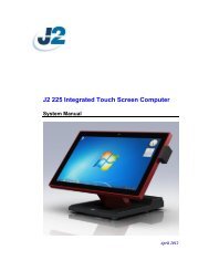
J2 680 Integrated Touchscreen Computer System Manual - Size
J2 680 Integrated Touchscreen Computer System Manual - Size
J2 680 Integrated Touchscreen Computer System Manual - Size

You also want an ePaper? Increase the reach of your titles
YUMPU automatically turns print PDFs into web optimized ePapers that Google loves.
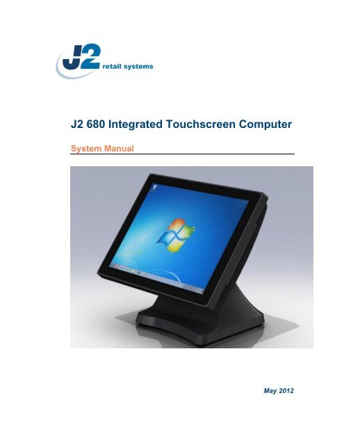
<strong>J2</strong> <strong>680</strong> <strong>Integrated</strong> <strong>Touchscreen</strong> <strong>Computer</strong><br />
<strong>System</strong> <strong>Manual</strong><br />
May 2012
Copyright © 2011-2012 <strong>J2</strong> Retail <strong>System</strong>s Ltd<br />
All rights reserved<br />
Change history<br />
Version 1.0 Release May 11, 2012<br />
<strong>J2</strong> <strong>680</strong> <strong>System</strong> <strong>Manual</strong><br />
Version 1.0 May 11, 2012<br />
2
Contents<br />
Overview ............................................................................................................................ 6<br />
Specification ....................................................................................................................... 8<br />
Features ............................................................................................................................ 10<br />
Intel’s Desktop Processor Socket LGA 1155 ............................................................... 10<br />
Hot Swappable RAID/ Dual Hard Drives ..................................................................... 10<br />
PoweredUSB Ports / Power Port................................................................................... 10<br />
UPS ............................................................................................................................... 11<br />
Printer Power Port ......................................................................................................... 11<br />
Cooling <strong>System</strong> ............................................................................................................. 11<br />
Fan-Off Mode ............................................................................................................... 11<br />
Versatility ...................................................................................................................... 11<br />
<strong>System</strong> .............................................................................................................................. 12<br />
Configurations ............................................................................................................... 12<br />
Processor Support ......................................................................................................... 12<br />
Processors currently supported on the <strong>680</strong> ................................................................... 13<br />
I/O Ports ........................................................................................................................ 14<br />
Off / On Button ............................................................................................................. 14<br />
Hard Disks .................................................................................................................... 15<br />
Zero Bezel Touch Screen .............................................................................................. 15<br />
<strong>System</strong> Board ................................................................................................................ 16<br />
LCD Display ................................................................................................................. 16<br />
Secondary Video Port(s) ............................................................................................... 16<br />
Serial ports .................................................................................................................... 18<br />
PoweredUSB Ports ........................................................................................................ 19<br />
Kensington Security Slot .............................................................................................. 20<br />
Audio ............................................................................................................................. 21<br />
Printer Power Port ......................................................................................................... 21<br />
Cash Drawer Port .......................................................................................................... 22<br />
CMOS Clear .................................................................................................................. 24<br />
Power Supply ................................................................................................................ 24<br />
Typical Power Consumption <strong>680</strong> .................................................................................. 25<br />
Service .............................................................................................................................. 26<br />
Removing the Head from the Base ............................................................................... 26<br />
Removing the Power Supply ........................................................................................ 27<br />
VESA Mounting ........................................................................................................... 28<br />
Optional Wall Mount Bracket Installation .................................................................... 29<br />
Removing the Back Cover ............................................................................................ 30<br />
Changing the <strong>System</strong> Board .......................................................................................... 31<br />
Adding Memory ............................................................................................................ 33<br />
Changing the Processor ................................................................................................. 33<br />
Accessing the HDD/SDD Drives .................................................................................. 34<br />
<strong>J2</strong> <strong>680</strong> <strong>System</strong> <strong>Manual</strong><br />
Version 1.0 May 11, 2012<br />
3
BIOS Setup ...................................................................................................................... 35<br />
Entering the BIOS Setup ............................................................................................... 35<br />
Main, <strong>System</strong> Overview ................................................................................................ 35<br />
Advanced Settings ........................................................................................................ 36<br />
Launch PXE ROM ........................................................................................................ 36<br />
SATA Configuration ..................................................................................................... 37<br />
Peripheral Power and LCD Brightness Configuration .................................................. 38<br />
Power Configure Screen ............................................................................................... 39<br />
Restore on AC Power Loss ........................................................................................... 39<br />
Wake on LAN ............................................................................................................... 39<br />
RTC Configuration ....................................................................................................... 39<br />
Boot Settings ................................................................................................................. 40<br />
Display OEM Logo ....................................................................................................... 40<br />
Exit Options .................................................................................................................. 41<br />
Driver Installation, Windows ......................................................................................... 42<br />
Chipset Driver Installation ............................................................................................ 42<br />
Graphics Driver Installation .......................................................................................... 42<br />
Audio Driver Installation .............................................................................................. 43<br />
LAN Driver Installation ................................................................................................ 44<br />
Multi-Touch Projected Capacitive Touch Driver ......................................................... 47<br />
Optional Multi-Touch Projected Capacitive Touch Driver .......................................... 49<br />
OPOS drivers ................................................................................................................ 51<br />
<strong>J2</strong> Health .......................................................................................................................... 52<br />
Installation ..................................................................................................................... 52<br />
Tray Icon ....................................................................................................................... 52<br />
Logging to File .............................................................................................................. 53<br />
Registry Entries ............................................................................................................. 54<br />
<strong>J2</strong> Remote Monitoring Software ................................................................................... 54<br />
SMI BIOS Info Utility .................................................................................................... 55<br />
Installation ..................................................................................................................... 55<br />
Operations ..................................................................................................................... 55<br />
Cash Drawer Test Utility ................................................................................................ 56<br />
Installation ..................................................................................................................... 56<br />
Operation ....................................................................................................................... 56<br />
<strong>J2</strong> Virtual Serial Ports Drivers ...................................................................................... 57<br />
RAID ................................................................................................................................ 58<br />
RAID Overview ............................................................................................................ 58<br />
AHCI ............................................................................................................................. 58<br />
Enabling RAID in the BIOS ......................................................................................... 59<br />
RAID Volume Creation ................................................................................................ 59<br />
<strong>J2</strong> <strong>680</strong> <strong>System</strong> <strong>Manual</strong><br />
Version 1.0 May 11, 2012<br />
4
F6 Installation Method .................................................................................................. 59<br />
Installing the Intel Matrix Storage Manager Software ................................................. 60<br />
Hot Swapping RAID 1 drives ....................................................................................... 60<br />
Packing List ..................................................................................................................... 63<br />
Standard Items .............................................................................................................. 63<br />
<strong>680</strong> Optional Peripherals ................................................................................................ 64<br />
MSR .................................................................................................................................. 64<br />
Overview ....................................................................................................................... 64<br />
Installing the <strong>680</strong> MSR ................................................................................................. 65<br />
Customer Display ............................................................................................................ 67<br />
Overview ....................................................................................................................... 67<br />
Secondary Video Display ................................................................................................ 67<br />
Fingerprint Reader / MSR ............................................................................................. 68<br />
iButton / MSR .................................................................................................................. 68<br />
<strong>680</strong> UPS ............................................................................................................................ 68<br />
RFID ................................................................................................................................. 68<br />
Wall Mount Bracket ....................................................................................................... 68<br />
Pole Mount Options ........................................................................................................ 68<br />
<strong>J2</strong> <strong>680</strong> <strong>System</strong> <strong>Manual</strong><br />
Version 1.0 May 11, 2012<br />
5
Overview<br />
The <strong>J2</strong> <strong>680</strong> is the second generation of very high performance integrated Point of Sale<br />
computer from <strong>J2</strong>. Built on the features and capabilities for the <strong>J2</strong> 650 the <strong>J2</strong> <strong>680</strong> offers<br />
even higher performance and expanded I/O. The <strong>J2</strong> <strong>680</strong> retains all the versatility of<br />
previous generation system and adds Quad core processor options, expanded I/O support<br />
with PoweredUSB, Intel remote management, HDMI video, Multi-Touch, Zero Bezel<br />
design and retains RAID and other important feature of the previous generation.<br />
This integrated touch screen computer like most <strong>J2</strong> designs features an “all in the head”<br />
design, which means it can be used as a counter top unit, a wall-mount or a pole-mounted<br />
computer. In this one small package you have the highest speed available intergraded or<br />
non-intergraded POS computer currently available.<br />
The <strong>J2</strong> <strong>680</strong> comes standard with an Intel 2.4GHz Dual Core Sandy Bridge processor but<br />
can also be order with a number of other processors including the very high end Intel i7<br />
3.4GHz Quad Core processor. The <strong>J2</strong> <strong>680</strong> system board uses the Intel LGA1155 socket<br />
and supports a wide range dual and quad core processors.<br />
Using the Intel Sandy Bridge processor with the Q67 chipset the <strong>J2</strong> <strong>680</strong> uses the latest<br />
high performance desktop solution in a very small footprint system. This solution<br />
provides for very high performance but with a very low carbon foot print. The Sandy<br />
bridge chipset is design only to draw as much power as need for any given operation<br />
greatly reducing the average power consumption for this level of performance.<br />
Designed for easy machine maintenance and upgradeability, the following is a list of<br />
important <strong>680</strong> features:<br />
1. Upgrades to the memory modules can be easily done by simply removing four<br />
screws on the back cover.<br />
2. A complete motherboard upgrade can be carried out in less than 1 minute.<br />
3. The two quick change SATA hard disk drives are easily accessible, housed on<br />
a slide-in drive bay that allows the drives to be hot swappable.<br />
4. The footprint of the <strong>J2</strong> <strong>680</strong> is particularly compact making it ideal for the space<br />
conscious retailer.<br />
The <strong>680</strong> supports the standard Microsoft operating systems, Windows 7, POSReady 7,<br />
Windows 7 Embedded, XP, POSReady 2009 and XP embedded. The <strong>680</strong> is equally<br />
proficient with the many flavors of Linux.<br />
<strong>J2</strong> <strong>680</strong> <strong>System</strong> <strong>Manual</strong><br />
Version 1.0 May 11, 2012<br />
6
<strong>J2</strong> <strong>680</strong> <strong>System</strong> <strong>Manual</strong><br />
Version 1.0 May 11, 2012<br />
7
Specification<br />
CPU Support<br />
Chipset<br />
<strong>System</strong> Memory<br />
Graphic memory<br />
BIOS<br />
LCD <strong>Size</strong><br />
Brightness<br />
Main board<br />
Intel Sandy Bridge Desktop Processors, socket LGA1155<br />
Intel Celeron Dual Core G530 up to Quad Core i7- 2600 3.4GHz<br />
Q67<br />
2 x 240-pin DDR3 DIMM 1333/1667MHz sockets - up to 16GB<br />
Share system memory 8MB~256MB<br />
LCD Touch Panel<br />
AMI<br />
15” TFT LCD<br />
250 nits, adjustable in 8 steps to 25nits<br />
Resolution 1024 x 768<br />
Touch Screen<br />
Multi-touch Project Capacitive or True Flat Resistive 5 wire<br />
Tilt Angle 0゜~ 90゜<br />
HDD/SSD<br />
USB<br />
Serial<br />
PoweredUSB<br />
LAN<br />
2 nd Display<br />
Cash Drawer<br />
Power In<br />
Audio Jack<br />
Printer Power<br />
Power LED<br />
Storage<br />
Two 2.5 inch SATA 3.0 drives support for HDD or SDD<br />
RAID 0 or 1, Quick Change-hot swap<br />
160GB HDD or 16GB SSD standard<br />
External I/O Ports<br />
6 total 2.0, 5 in cable well, 1 on side, 3 are PoweredUSB<br />
Four DB9 RS-232 with power option<br />
2 +12V PoweredUSB and 1 +24V PoweredUSB<br />
10 /100/ 1000 Intel 82579LM Controller<br />
One VGA port and One DisplayPort<br />
DisplayPort supports HDMI and DVI displays<br />
2 x RJ 11 24V with status<br />
19VDC 9.47 amps<br />
One headset, one microphone-in<br />
+24 V 2.5 amps, supports most 24V POS printers<br />
Front bezel, green for on, amber for standby<br />
<strong>J2</strong> <strong>680</strong> <strong>System</strong> <strong>Manual</strong><br />
Version 1.0 May 11, 2012<br />
8
Power<br />
Power Adapter 19VDC, 180W, 100-240 VAC,50~60Hz, 2.5A<br />
MSR<br />
iButton<br />
Fingerprint Reader<br />
RFID<br />
2-in-1<br />
2-in-1<br />
Second Display<br />
Customer Display<br />
UPS<br />
Standard<br />
Optional<br />
EMC & Safety<br />
Operating<br />
Temperature<br />
Storage<br />
Temperature<br />
Operating Humidity<br />
Storage Humidity<br />
Dimensions<br />
(W x D x H)<br />
Weight<br />
OS Support<br />
Optional Peripheral<br />
3 Track<br />
Dallas Key iButton<br />
USB Digital Persona Fingerprint Reader<br />
125KHz RFID USB<br />
MSR 3 track / Finger Print<br />
MSR 3 track / iButton<br />
4:3 displays, 8.4”, 10.4” or 12.1” with or without touch<br />
16:9 displays, 10.1” or 14” with or without touch<br />
2x20 VFD<br />
DC UPS, 0.5-1.5 hours run time<br />
Mounting<br />
Counter Top Base, Adjustable Viewing Angle 0-90°<br />
100mm VESA mounting point<br />
Pole Mount, Adjustable angle VESA, Swing-arm Mounts, others<br />
Environment<br />
FCC, Class A, CE, LVD<br />
0 ~ 40℃<br />
-20 ~ 55℃<br />
20% ~ 80% RH non-condensing<br />
20% ~ 85% RH non-condensing<br />
370 x 250 x325mm<br />
8.1kg<br />
Windows 7, POSReady 7, Windows 7 Embedded, XP,<br />
POSReady 2009, XP Embedded, version of Linux<br />
* This specification is subject to change without prior notice.<br />
<strong>J2</strong> <strong>680</strong> <strong>System</strong> <strong>Manual</strong><br />
Version 1.0 May 11, 2012<br />
9
Features<br />
Intel’s Desktop Processor Socket LGA 1155<br />
By using the latest generation of Intel’s desktop processors and chipsets, code named<br />
Sandy Bridge, the <strong>J2</strong> <strong>680</strong> supports a very wide range of processors. By taking advantage<br />
of <strong>J2</strong> company’s and partners’ vast experience with notebook, desktop, and POS<br />
computer designs, we are able to combine features of all three for an optimal POS system<br />
design. The result is a POS system that can utilize a desktop chipset that draws very little<br />
power and generates a low amount of heat, similar to mobile chipsets and processors.<br />
Notebook quality components are used in the processor, chipset, and power supply<br />
circuit, which allows for reduced heat generation and minimal power usage.<br />
Additionally, the <strong>680</strong> takes full advantage of the low power features built into the Intel<br />
processor and chipset to further reduce heat.<br />
Hot Swappable RAID/ Dual Hard Drives<br />
Like the <strong>J2</strong> 650, the first integrated POS system on the market to offer a hot swappable<br />
RAID feature the <strong>J2</strong> <strong>680</strong> also supports this feature. The two internal 2.5 inch SATA hard<br />
drives can be configured as a RAID array which gives true fault tolerance to the hard<br />
drive subsystem.<br />
PoweredUSB Ports / Power Port<br />
Addressing the need for additional power ports the <strong>J2</strong> <strong>680</strong> supports two +12V and one<br />
+24V PoweredUSB ports. The <strong>J2</strong> <strong>680</strong> can take advantage of growing availably or<br />
PoweredUSB products on the market.<br />
In addition to the three PoweredUSB port the <strong>J2</strong> <strong>680</strong> also support four powered serial<br />
ports, and VGA +12V power, a +24V printer power port and 3 standard 2.0 USB ports.<br />
By using a combination of these powered ports most all additional external power<br />
supplies for devices like scales, scanner, “Chip and Pin” devices, scanners, secondary<br />
display and other can be eliminated. This save space and reduces cost, cables and<br />
powered consumption. Also in most installs this means only one AC power point is<br />
needed. In additional with <strong>J2</strong> optional UPS all these devices will be powered during a<br />
power outage.<br />
<strong>J2</strong> <strong>680</strong> <strong>System</strong> <strong>Manual</strong><br />
Version 1.0 May 11, 2012<br />
10
UPS<br />
Not your ordinary UPS, the <strong>J2</strong> <strong>680</strong> UPS is a DC, not an AC UPS. The UPS fits<br />
conveniently into the base of the unit. Unlike an AC UPS the <strong>J2</strong> UPS makes the <strong>680</strong> work<br />
more like a notebook computer. In addition to running the <strong>680</strong> for up one hour, the UPS<br />
will run all the POS peripherals attached to the <strong>680</strong>, including the printer. Because of the<br />
unique design of the <strong>J2</strong> UPS and power supply, the need for special AC power<br />
conditioning devices is eliminated.<br />
Printer Power Port<br />
The 24 volt Printer Power Port can power most POS printers on the market, including the<br />
popular Epson line of printers. When used along with the <strong>J2</strong> UPS, if a power outage<br />
should occur, the POS terminal can still operate and print receipts for up to one hour.<br />
Also, when the <strong>680</strong> is turned off the printer is turned off also. This is very useful when<br />
the auto power on and off features of the <strong>680</strong> is used. This also applies to the +24V<br />
PoweredUSB port (note, only one +24V port can be used at a time).<br />
Cooling <strong>System</strong><br />
Great attention was paid to the thermal solution of the <strong>680</strong>, it is truly a unique feature.<br />
The <strong>680</strong> can run as a fan less or fan-cooled system. Because of the very wide range of<br />
processors supported, thermal loads can range from 5 watts to as high as 95 watts. The<br />
<strong>680</strong> was designed to handle these thermal loads while still being super quiet. Two smart<br />
fans are used in conjunction with an Embedded Controller (EC) to ensure that the fans<br />
run at the lowest possible speed while still providing proper cooling. Fan speed changes<br />
are controlled to produce the smallest acoustical signature possible. The <strong>680</strong> fans are the<br />
type used in Blade Servers and have a speed range from 3500~10,000 rpms at very high<br />
torque.<br />
Fan-Off Mode<br />
When using the i5 or lower performance processor the <strong>680</strong> can run in a fan-off<br />
configuration. In the mode the <strong>680</strong> is a fan-less convection cooled device. This fan less<br />
operation may be required for high dust or other special environments.<br />
This feature is unique to <strong>J2</strong> and was supported by the <strong>J2</strong> 650 “Green Mode”. With the <strong>J2</strong><br />
<strong>680</strong>’s “Fan-Off” mode power is also greatly reduced by the nature of the processor used<br />
reducing power consumption and thereby reducing the units’ carbon foot print.<br />
Versatility<br />
The word versatility is very much over used, but it is the correct word to describe the<br />
most unique feature of the <strong>680</strong>. The combination of all the <strong>680</strong> unique features allows for<br />
the <strong>680</strong> to fit many roles. The <strong>680</strong> is not just one product, but a full product range all in<br />
one system. From fan less thin client to Quad Core RAID Server - the <strong>680</strong> does it all.<br />
<strong>J2</strong> <strong>680</strong> <strong>System</strong> <strong>Manual</strong><br />
Version 1.0 May 11, 2012<br />
11
<strong>System</strong><br />
Configurations<br />
The <strong>680</strong> can be ordered or upgraded to many possible configurations. Selecting the right<br />
combination of memory, processor, hard or solid state drive(s), and software drivers can<br />
dramatically change the performance of the <strong>680</strong> system. For a lot of users the standard<br />
530 2.4GHz dual core processor and 2GB of memory is fine, as this is already more<br />
powerful most all POS systems, but some applications may require more horse power. In<br />
this case the <strong>J2</strong> <strong>680</strong> could be configured with a quad core i5 or i7 processor.<br />
<strong>J2</strong> will be happy to help you determine what you may require from the <strong>680</strong> in the most<br />
cost effective way. More memory may be added to get the performance needed, or<br />
sometimes a quad core processor and dual HDD with RAID are needed. The <strong>680</strong> can do<br />
it all, low end to high end.<br />
Processor Support<br />
The <strong>680</strong> supports a very wide range of Intel processors. Each provides a different price<br />
performance level. From Celeron dual core, Pentium dual core and -3, i5 and i7 dual a<br />
quad core with processor speeds from 2.4GHz to 3.4GHz are all supported by the <strong>680</strong>.<br />
The <strong>680</strong> comes standard with the Intel dual core 2.4 GHz G530 processor but can be<br />
ordered with a different processor type. The processor can be easily upgraded by a<br />
qualified technician. The <strong>680</strong> uses the Intel defined LGA1155 socket. Intel is constantly<br />
adding new processors so please check with <strong>J2</strong> for any additions since publication of this<br />
manual.<br />
The large heat sink, cooling fans, and fan controller (shown below) are designed to keep<br />
everything running cool, quiet, and reliably with the supported processors.<br />
<strong>System</strong> Board, back view<br />
<strong>J2</strong> <strong>680</strong> <strong>System</strong> <strong>Manual</strong><br />
Version 1.0 May 11, 2012<br />
12
Processors currently supported on the <strong>680</strong><br />
Processor # Intel's Family name Clock Speed<br />
Max Turbo<br />
Fan-off Graphics Speed<br />
Max<br />
# of Cores # of Threads Cache Embedded<br />
VPro<br />
Frequency<br />
mode MHz<br />
TDP<br />
G530T Celeron 2.0 GHz Na 2 2 2MB No Yes 650/1000 No 35 W<br />
G530 Celeron 2.4 GHz Na 2 2 2 MB No No 850/1000 No 65 W<br />
G540 Celeron 2.5 GHz Na 2 2 2 MB Yes No 850/1000 No 65 W<br />
G620T Pentium 2.2 GHz Na 2 2 3 MB 7 Year Yes 650/1100 No 35 W<br />
G620 Pentium 2.6 GHz Na 2 2 3 MB No No 850/1100 No 65 W<br />
G630 Pentium 2.7 GHz Na 2 2 3 MB No No 850/1100 No 65 W<br />
G630T Pentium 2.3 GHz Na 2 2 3 MB No Yes 650/1100 No 35 W<br />
G840 Pentium 2.8 GHz Na 2 2 3 MB No No 850/1100 No 65 W<br />
G850 Pentium 2.9 GHz Na 2 2 3 MB Yes No 850/1100 No 65 W<br />
G860 Pentium 3.0 GHz Na 2 2 3 MB No No 850/1100 No 65 W<br />
i3-2100 i3 3.1 GHz Na 2 4 3 MB No No 850/1100 No 65 W<br />
i3-2100T i3 2.5 GHz Na 2 4 3 MB 7 Year Yes 650/1100 No 35 W<br />
i3-2120 i3 3.3 GHz Na 2 4 3 MB Yes No 850/1100 No 65 W<br />
i3-2120T i3 2.6 GHz Na 2 4 3 MB No Yes 650/1100 No 35 W<br />
i3-2125 i3 3.3 GHz Na 2 4 3 MB No No 850/1100 No 65 W<br />
i3-2130 i3 3.4 GHz Na 2 4 3 MB No No 850/1100 No 65 W<br />
i5-2390T i5 2.7 GHz 3.5 GHz 2 2 3 MB 7 Year Yes 650/1100 Yes 35 W<br />
i5-2300 i5 2.8 GHz 3.1 GHz 4 4 6 MB No No 850/1100 No 95 W<br />
i5-2310 i5 2.9 GHz 3.1 GHz 4 4 6 MB No No 850/1100 No 95 W<br />
i5-2320 i5 3.0 GHz 3.1 GHz 4 4 6 MB No No 850/1100 No 95 W<br />
i5-2400 i5 3.1 GHz 3.4 GHz 4 4 6 MB Yes No 850/1100 Yes 95 W<br />
i5-2400S i5 2.5 GHz 3.3 GHz 4 4 6 MB No No 850/1100 Yes 65 W<br />
i5-2500 i5 3.3 GHz 3.7 GHz 4 4 6 MB No No 850/1100 Yes 95 W<br />
i5-2500S i5 2.7 GHz 3.7 GHz 4 4 6 MB No No 850/1100 Yes 65 W<br />
i5-2500T i5 2.3 GHz 3.3 GHz 4 4 6 MB No Yes 650/1250 Yes 45 W<br />
i7-2600 i7 3.4 GHz 3.8 GHz 4 8 8 MB Yes No 850/1350 Yes 95 W<br />
i7-2600S i7 2.8 GHz 3.8 GHz 4 8 8 MB No No 850/1350 Yes 65 W<br />
1: Processor with green shading would be standard <strong>680</strong> products.<br />
2: Processor with blue shading are available but may requires a minimum order quantity.<br />
3: All processor shown above should work on the <strong>J2</strong> <strong>680</strong> but are not necessarily tested.<br />
4: "7 Year" = support from Intel to <strong>J2</strong> for 7 years, same as embedded products.
I/O Ports<br />
Most I/O ports are accessible in the cable well at the bottom of the unit. A cover plate is<br />
provided to cover the cables.<br />
I/O Panel<br />
Off / On Button<br />
The Off /On button is located in the cable well, as shown. This button is located near the<br />
side to prevent accidental powering down by the user. The function of the button can be<br />
controlled by the OS. If the <strong>680</strong> hangs for some reason it can always be powered off by<br />
holding the Off / On button in for six seconds.<br />
The <strong>680</strong> also supports the following: Restore on AC on power loss, Wake On LAN, and<br />
Wake On RTC alarm features to control the system power up.<br />
Off / On button Location
Hard Disks<br />
Two 2.5 inch SATA hard drives (HDD) or solid state drives (SSD) are supported. These<br />
drives can be configured as standard hard drives or as a RAID array. The SATA interface<br />
can support data transfer rates up to 6.0 Gb/s and supports AHCI and Hot Swapping of<br />
hard drives.<br />
The HDDs can easily be accessed by removing a panel on the left side of the unit. HDDs<br />
can be installed or removed in seconds by removing one screw. A carrying tray (two of<br />
which are supplied with the <strong>680</strong>) fits onto a new drive without tools. The drive can now<br />
easily be slid into the drive bay. In a RAID 1 configuration a drive can be hot swapped,<br />
removed, or inserted with the power on (see section on RAID setup).<br />
HDD access panel<br />
HDD slide in-slide out drive bay<br />
Zero Bezel Touch Screen<br />
The <strong>680</strong>PTC unit uses a Multi-Touch Projected Capacitive technology touch screen<br />
(PCT). The PCT touch screen has no known failure mode-- it does not “wear out.” This<br />
screen is made with tempered glass and does not reduce the brightness of the LCD panel.<br />
When operating in a very high use environment PCT is the recommended touch screen<br />
technology. The PCT touch screen will work with most gloves and stylus designed to<br />
work with tablet computers. The screen has a smooth glass surface that is reflective.<br />
The <strong>680</strong>TFR uses a five-wire touch screen rated at 35 million touches per point. The<br />
resistive technology is very responsive and is the traditional choice for a hospitality POS<br />
system. The screen has an anti-reflective plastic film surface.<br />
Both screens are fully spill proof, dust proof and can be cleared with and standard glass<br />
cleaner. The zero bezel, sometimes called true flat, design allow for this plus easy<br />
cleaning. The <strong>680</strong> touch screen was designed to easily be changed, normally in less than<br />
two minutes. Depending on operating environment and usage, both the Resistive and<br />
PCT touch screens have strengths and weaknesses. <strong>J2</strong> offers both touch screen<br />
technologies on the <strong>680</strong>.<br />
<strong>J2</strong> <strong>680</strong> <strong>System</strong> <strong>Manual</strong><br />
Version 1.0 May 11, 2012<br />
15
<strong>System</strong> Board<br />
POS computers typically have a desired lifespan of 10 years or longer, therefore product<br />
quality is of the utmost importance. The <strong>680</strong> electronics are built with high-end<br />
components to ensure reliability and long lasting product performance.<br />
The system board is designed for quick replacement and only has one connection, an<br />
edge pin connector, to which all motherboard connections are made.<br />
<strong>System</strong> board<br />
LCD Display<br />
The LCD display for the <strong>680</strong> is a 1024 x 768 resolution display with 16.2 Million colors.<br />
The brightness is rated at 250cd/m 2 . The Intel controller allows for the display to be<br />
rotated to 0, 90, 180 or 270 degrees without loss of performance.<br />
The LCD brightness can be controlled in 8 steps, from 250 cd/m 2 to 25 cd/m 2 . The<br />
brightness can be set to a fixed level in the BIOS or controlled by a utility supplied by <strong>J2</strong>.<br />
Secondary Video Port(s)<br />
A standard PC VGA video port is supported on the <strong>680</strong> and can be set as the primary or<br />
secondary display The VGA video port has an industry standard HD DB15 connector.<br />
When used with some <strong>J2</strong> monitors the display can be powered by the <strong>680</strong> through this<br />
connector.<br />
<strong>J2</strong> <strong>680</strong> <strong>System</strong> <strong>Manual</strong><br />
Version 1.0 May 11, 2012<br />
16
The <strong>680</strong> also supports the newer digital video standard DisplayPort connector. This<br />
connector supports a DisplayPort monitor or a HDMI display or DVI monitor. When<br />
used with HMDI or DVI display a passive adapter cable is used. When used with a<br />
HDMI display Audio is support via the same HMDI cable.<br />
The secondary video displays can be configured as a Twin, Intel Dual Display Clone, or<br />
Extended Desktop. Most all monitor resolutions from 640 x 480 to 2560 x 2048 are<br />
supported.<br />
Note that only one external video display is support at a time, either on the VGA video<br />
port or the DisplayPort video port.<br />
VGA and DisplayPort Video Ports<br />
<strong>J2</strong> <strong>680</strong> <strong>System</strong> <strong>Manual</strong><br />
Version 1.0 May 11, 2012<br />
17
Serial ports<br />
The <strong>680</strong> has four external RS232 serial ports, all of which can be powered. The serial<br />
ports are standard RS-232 ports with a DB9 male connector. The serial ports, in a normal<br />
configuration, are mapped to COM 1-4.<br />
There also four internal serial ports one of which is used for the resistive touch controller<br />
and the other are reserved for other internal options.<br />
COM ports 1-4 can supply power to an external device when required, like the optional<br />
<strong>J2</strong> Customer Display. COM 1 can supply +5 volt and COM 2-4 supply +12 volts. The<br />
voltage is supplied on pin 9 (RI) of the DB9 connector. The maximum current is 1000ma<br />
and is over-current protected. A BIOS setting is used to enable the voltage on each port.<br />
<strong>J2</strong> does not normally recommend using the +5 volt option on COM 1 and is only there for<br />
some legacy devices. The problem is it easy for +5 volt device to be plugged into a +12<br />
enable serial port by mistake which will burn out the +5 volt device. A good alternative<br />
to powering a +5 volt serial device, or any +5V device would be to use power from an<br />
unused USB port. Cables for this are readily available (see below).<br />
DB9 pin out serial ports<br />
Pin RS232<br />
1 DCD<br />
2 RD<br />
3 TD<br />
4 DTR<br />
5 GND<br />
6 DSR<br />
7 RTS<br />
8 CTS<br />
9 RI<br />
Serial Port<br />
USB to +5V cable<br />
<strong>J2</strong> <strong>680</strong> <strong>System</strong> <strong>Manual</strong><br />
Version 1.0 May 11, 2012<br />
18
USB Ports<br />
The <strong>680</strong> has six external and 4 internal USB 2.0 ports. Of the six external ports (see<br />
below) five ports are located in the cable well and one is located on the left side of the<br />
unit for easy access. The four internal USB ports are as follows: one can be used for the<br />
optional Finger Print Reader and is located on the MSR connecting point. The second<br />
internal USB port is used for the PCT touch screen controller and the other internal USB<br />
ports is designed for other optional internal devices. All the <strong>J2</strong> <strong>680</strong> USB ports can supply<br />
1000ma of power, 500ma more than the normal for the USB specification.<br />
PoweredUSB Ports<br />
Of the 6 external USB 2.0 ports 3 are PoweredUSB ports. Located in the cable well are<br />
two +12V PoweredUSB ports and one +24V PoweredUSB port. These ports conform to<br />
the PoweredUSB standard.<br />
It should be noted that these three ports can also be used as standard USB ports as well.<br />
Normal +5 USB devices will plug into the bottom half of the connector without a<br />
problem.<br />
USB Ports<br />
Side USB Port<br />
<strong>J2</strong> <strong>680</strong> <strong>System</strong> <strong>Manual</strong><br />
Version 1.0 May 11, 2012<br />
19
Ethernet Connection<br />
The <strong>680</strong> uses the Intel 82579LM Gigabit Ethernet controller. The Ethernet connector is<br />
located in the cable well, as shown below. The Ethernet controller supports Wake on<br />
LAN, the BIOS supports a PXE boot ROM as well. There are two LEDs on the LAN<br />
connector: the Green LED lights up when the LINK signal is present and the Amber<br />
LED lights comes on when there is LAN activity. This Ethernet supports Intel AMT<br />
feature when used with the correct processor.<br />
Ethernet Connector<br />
Kensington Security Slot<br />
There is a Kensington Security Slot (lock slot) on the <strong>680</strong>. (Please see below).<br />
It is located on the head in the cable well. The Kensington locks are normally used as a<br />
deterrent to prevent opportunistic theft. Most retail locks will work with the <strong>680</strong>, however<br />
please check to see if a lock fits, as not all do.<br />
Kensington slot Cable Well<br />
<strong>J2</strong> <strong>680</strong> <strong>System</strong> <strong>Manual</strong><br />
Version 1.0 May 11, 2012<br />
20
Audio<br />
The <strong>680</strong> uses the VIA1708B HD audio controller. There is one internal speaker.<br />
Both a microphone jack and a headset jack are located in the cable well of the <strong>680</strong>, as<br />
seen below, which allows for the connection of a microphone and headset or audio out to<br />
other devices. Audio is also output via the HDMI port when used.<br />
Audio Jack Location<br />
Printer Power Port<br />
The Printer Power Port allows an industry standard POS printer to be powered from the<br />
<strong>680</strong> and eliminates the need for a separate external power supply for the printer.<br />
The Printer Power Port supplies 24 VDC 2.5 amps and 6.0 amp surge current which will<br />
run most POS printers on the market. The power cable for this port is supplied standard<br />
with the <strong>680</strong> unit. The Printer Power Port will also supply power to a printer even when<br />
running on the optional UPS. When the <strong>680</strong> is powered down, then power to the printer is<br />
turned off. This same power circuit is used by the +24 PoweredUSB port and normally<br />
only one +24V device is supported at one time.<br />
Printer Power Port<br />
Printer Power Port Cable<br />
<strong>J2</strong> <strong>680</strong> <strong>System</strong> <strong>Manual</strong><br />
Version 1.0 May 11, 2012<br />
21
Cash Drawer Port<br />
The <strong>680</strong> is equipped with one Cash Drawer port that will support one or two drawers.<br />
This port is located in the cable well and uses the industry standard RJ-11 connector and<br />
pin out (illustrated below). This pin-out is the same as used by EPSON printers and<br />
cables for the EPSON printer normally work with the <strong>680</strong>.<br />
Cash Drawer Ports<br />
Cash Drawer 1 Pin Assignment<br />
6 1<br />
Pin<br />
Signal<br />
1 GND<br />
2 CD1 SOLENOID<br />
3 STATUS / STATUS CD1<br />
4 24V<br />
5 CD2 SOLENOID<br />
6 GND / STATUS CD2<br />
The application may address the Cash Drawer port in two ways:<br />
1) Using the <strong>J2</strong>-supplied OPOS drivers for Windows.<br />
2) Direct access to the I/O ports<br />
3) <strong>J2</strong> supplied Virtual Serial Cash Drawer Emulator<br />
<strong>J2</strong> <strong>680</strong> <strong>System</strong> <strong>Manual</strong><br />
Version 1.0 May 11, 2012<br />
22
Cash Drawer Controller Register<br />
The Cash Drawer Controller use one I/O address to control the Cash Drawer.<br />
Register Location: 48Ch<br />
Attribute: Read / Write<br />
<strong>Size</strong>: 8bit<br />
BIT BIT7 BIT6 BIT5 BIT4 BIT3 BIT2 BIT1 BIT0<br />
Attribute Read Reserved Write Reserved<br />
7 6 5 4 3 2 1 0<br />
X X X X X<br />
Reserved<br />
Cash Drawer 1 fire<br />
Cash Drawer 2 fire<br />
Reserved<br />
Cash Drawer 1 status<br />
Reserved<br />
The “Y” cable used to support two cash drawers on the one RJ-11 is the same as is used<br />
on Epson printers.<br />
<strong>J2</strong> <strong>680</strong> <strong>System</strong> <strong>Manual</strong><br />
Version 1.0 May 11, 2012<br />
23
CMOS Clear<br />
The <strong>680</strong> CMOS can be cleared jumping JP3 pin 1-2 then removing the jumper.<br />
JP3<br />
Power Supply<br />
The <strong>680</strong> uses a notebook type power supply that is normally mounted in the base of the<br />
unit. The power supply is rated with an output of 180 watts 19 VDC 9.47 Amps and has<br />
an input rating of 100-240VAC at 50~60Hz 2.5Amps maximum. The power supply has<br />
an efficiency rating IV. The power supply connector is a four pin locking type that plugs<br />
into the system’s power input connector located in the cable well.<br />
Power Input connector<br />
<strong>J2</strong> <strong>680</strong> <strong>System</strong> <strong>Manual</strong><br />
Version 1.0 May 11, 2012<br />
24
Typical Power Consumption <strong>680</strong><br />
The typical power consumption of the <strong>680</strong> is lower that most desktop computers. Using<br />
the latest generation on Intel’s Desktop processors and chipset allows for much lower<br />
power consumption than previous generations of POS computer. This when coupled with<br />
proper system configuration can greatly reduce the systems total carbon foot print.<br />
Test conditions<br />
Voltage:<br />
220VAC 50Hz, measured voltage 236 VAC<br />
OS: POSReady 7<br />
Heavy Load Program: PassMark BurnInTest defaults values<br />
Maximum load: PassMark BurnInTest Max CPU Temp<br />
Temperature: 26c<br />
All system where tested in there standard hard drive configuration. Results are +/- 15%.<br />
<strong>J2</strong> <strong>680</strong> G850 2.9GHz Pentium<br />
1: Normal application including most POS software 40 watts<br />
2: Very heavy load application 57 watts<br />
3: Maximum load 64 watts<br />
4: Normal POS app, back light off 20 watts<br />
5: Standby, unit off, waiting for wake on LAN, RTC or power button >4 watts<br />
<strong>J2</strong> <strong>680</strong> <strong>System</strong> <strong>Manual</strong><br />
Version 1.0 May 11, 2012<br />
25
Service<br />
Removing the Head from the Base<br />
The <strong>680</strong> is shipped with a counter top base which allows for the head to be adjusted from<br />
0-90°.<br />
To remove the integrated head from the base, fully loosen the thumbscrew located on the<br />
back of the unit under the hinge of the counter top base, as shown below. Then lift the<br />
head as illustrated:<br />
Loosen Thumb Screw<br />
Slide Head up to remove<br />
<strong>J2</strong> <strong>680</strong> <strong>System</strong> <strong>Manual</strong><br />
Version 1.0 May 11, 2012<br />
26
Removing the Power Supply<br />
The power supply is normally located in the counter top base. When using a wall mount<br />
bracket or the <strong>J2</strong> UPS, the power supply would be external from the unit.<br />
To remove the power supply from the base, three screws needs to be removed as shown.<br />
Screw locations<br />
<strong>J2</strong> <strong>680</strong> <strong>System</strong> <strong>Manual</strong><br />
Version 1.0 May 11, 2012<br />
27
VESA Mounting<br />
The <strong>680</strong> unit also supports the industry standard 100mm VESA mounting. The same<br />
mounting hard point used for the counter top base is used for VESA mounting. The four<br />
point that thread holes for 4mm screws.<br />
100mm VESA Pattern<br />
Threaded Mounting point(s), 4mm screw<br />
<strong>J2</strong> <strong>680</strong> <strong>System</strong> <strong>Manual</strong><br />
Version 1.0 May 11, 2012<br />
28
Optional Wall Mount Bracket Installation<br />
The wall mount bracket has threaded mounting holes (screws provided) for the 75mm<br />
VESA standard; and unthreaded holes for the 100mm standard.<br />
Using the 100mm hole pattern the bracket can be used by itself as a wall mount bracket.<br />
After installing the thumbscrew clip mount bracket to the wall, hang the <strong>J2</strong> <strong>680</strong> on the<br />
bracket.<br />
Install screw to secure thumbscrew clip<br />
The bracket slides on to the <strong>J2</strong> <strong>680</strong> mount posts, as shown. Normally the bracket would<br />
already be mounted to the wall or a VESA mount and the <strong>680</strong> would be hung on the<br />
bracket. Once in place the thumb screw would be tightened.<br />
<strong>J2</strong> <strong>680</strong> <strong>System</strong> <strong>Manual</strong><br />
Version 1.0 May 11, 2012<br />
29
Removing the Back Cover<br />
The following steps show how to disassemble the <strong>680</strong> for servicing:<br />
On a clean, protected surface, place the unit screen-side down. Remove the four cover<br />
screws as shown. Carefully lift the back cover as shown.<br />
Remove four screws where shown<br />
Carefully tilt up the back cover to remove<br />
Note: The <strong>680</strong> was designed so that the internals of the unit could be accessed without<br />
having to remove the mounting base or the mounting bracket of the unit.<br />
<strong>J2</strong> <strong>680</strong> <strong>System</strong> <strong>Manual</strong><br />
Version 1.0 May 11, 2012<br />
30
Changing the <strong>System</strong> Board<br />
*Special Note: An anti-static workplace with proper grounding is required when<br />
changing the <strong>System</strong> Board.<br />
First remove the back cover. There are 3 screws that hold the system board in place that<br />
will need to be removed. (see photo below)<br />
Three screws to remove <strong>System</strong> Board<br />
<strong>J2</strong> <strong>680</strong> <strong>System</strong> <strong>Manual</strong><br />
Version 1.0 May 11, 2012<br />
31
After the screws are removed the system board can be unplugged from its connector.<br />
While using the I/O bracket to pull on, slide the board out towards the bottom of the unit<br />
as shown.<br />
When reinstalling the system board make sure the locking tabs on the bottom of the board<br />
lock into their mating slots.<br />
<strong>J2</strong> <strong>680</strong> <strong>System</strong> <strong>Manual</strong><br />
Version 1.0 May 11, 2012<br />
32
Adding Memory<br />
Note: An anti-static workplace with proper grounding is required when adding<br />
memory. Remove the back cover. You can now access the two memory sockets, the<br />
order in which the memory is populated does not matter.<br />
The <strong>J2</strong> <strong>680</strong> supports up to 16GB of memory in two sockets. Memory type is 240 DIMM<br />
DDR3 1066/1333.<br />
Memory sockets<br />
Changing the Processor<br />
To change the processor, first start by working in an anti-static workplace with<br />
proper grounding. Remove the back cover by removing the four screws; now remove<br />
the black plastic fan duct.<br />
Loosen the four spring-loaded screws that secure the processor heat sink by loosening.<br />
Each screw about two turns at a time so that the pressure is removed from the socket<br />
evenly. Once the screws are free you will now be able to remove the heat sink.<br />
It will stick because of the heat sink compound, so take care to move it gently from side<br />
to side until it comes off. Set the heat sink aside, top side down.<br />
You can now remove the processor from the socket. Push the locking lever down, push<br />
out from the locking tab, and move up as shown. Now carefully lift the cover up and you<br />
can remove the processor. **Be sure only to touch the edges of the processor and do<br />
not touch the processor pads of the socket pins. These socket pins are very easy to<br />
bend and damage to the socket is not covered by <strong>J2</strong>’s warranty.<br />
<strong>J2</strong> <strong>680</strong> <strong>System</strong> <strong>Manual</strong><br />
Version 1.0 May 11, 2012<br />
33
Accessing the HDD/SDD Drives<br />
Remove cover screw then remove cover<br />
Remove or insert drive as needed<br />
The HDD/SSD may be hot swapped when in a RAID 1 configuration. In non-RAID 1<br />
configurations the unit should be powered down before changing a drive or data may be<br />
lost. No physical damage will happen to the HDD if inserted or removed with power on.<br />
<strong>J2</strong> <strong>680</strong> <strong>System</strong> <strong>Manual</strong><br />
Version 1.0 May 11, 2012<br />
34
BIOS Setup<br />
Entering the BIOS Setup<br />
To enter the BIOS Setup, turn on or reboot the <strong>680</strong> and press the DEL key after the BIOS<br />
sign-on screen appears. The main menu of the BIOS setup will be displayed, this can take<br />
a few seconds. If the supervisor password is set, you must enter it here. The area on the<br />
right side of the screen displays a help window for the current screen or BIOS option.<br />
BIOS setting should only be change by qualified personal as changing some setting can<br />
cause the system not to function properly.<br />
Main, <strong>System</strong> Overview<br />
In this screen the system time and date are displayed and can be set. The time and date<br />
can also be set through the OS. This screen also displays the BIOS version (project),<br />
BIOS Build Date, CPU type, CPU speed and DRAM memory size, Product type, <strong>System</strong><br />
Serial Number and mother board revision. The serial number of the mother board and the<br />
system are the same.<br />
Main screen<br />
<strong>J2</strong> <strong>680</strong> <strong>System</strong> <strong>Manual</strong><br />
Version 1.0 May 11, 2012<br />
35
Advanced Settings<br />
This menu contains settings to control a number of system functions. Most these settings<br />
are self-explanatory.<br />
Advanced Setting Screen<br />
Launch PXE ROM<br />
This setting enables the built- in PXE LAN remote boot rom. This allows the system to<br />
run as a diskless workstation, or to be able to download a drive image to a blank drive.<br />
When enabled, a message screen will appear and Shift-F10 can be typed to access the<br />
PXE ROM options. This option is located on the “Advanced” tab as shown above.<br />
<strong>J2</strong> <strong>680</strong> <strong>System</strong> <strong>Manual</strong><br />
Version 1.0 May 11, 2012<br />
36
SATA Configuration<br />
In this screen the SATA hard drives can be set to work in one of three modes, SATA,<br />
RAID or AHCI.<br />
When set to SATA, the SATA drive works the same as a normal IDE HDD. This is the<br />
IDE compatible mode and default BIOS setting. The other two selections are RAID and<br />
AHCI modes. Please see the separate section in the manual for RAID Setup for further<br />
information on using RAID and AHCI modes.<br />
SATA Configuration Screen<br />
<strong>J2</strong> <strong>680</strong> <strong>System</strong> <strong>Manual</strong><br />
Version 1.0 May 11, 2012<br />
37
Peripheral Power and LCD Brightness Configuration<br />
This submenu allows for the enabling of power for the serial ports, default cash drawer<br />
pulse timing and default LCD brightness level and power for a <strong>J2</strong> supplied VGA port<br />
monitor.<br />
Power enable for serial Ports<br />
LCD Brightness Setting<br />
<strong>J2</strong> <strong>680</strong> <strong>System</strong> <strong>Manual</strong><br />
Version 1.0 May 11, 2012<br />
38
Power Configure Screen<br />
Power Configure Screen<br />
Restore on AC Power Loss<br />
The <strong>680</strong> has three options should AC power become lost and then restored. There is<br />
Power Off (stay turned off), Power On (turn on when AC restored), or Last State. The<br />
Last State setting will cause the unit to turn on if it was on when AC power was lost or it<br />
will stay off if the unit was off when AC power was lost.<br />
Wake on LAN<br />
Wake on LAN is enabled by default but can be disabled in this screen.<br />
RTC Configuration<br />
The RTC has an alarm function that can be used to turn the <strong>680</strong> on at a preset time of<br />
day. This function is enabled by this setting. The wake up time can also be set here.<br />
<strong>J2</strong> also has available a utility to set the wake-up time from Windows. This is more<br />
versatile than the BIOS setting as it allows for more than one time of day to be set as well<br />
as days of the week to turn on.<br />
<strong>J2</strong> <strong>680</strong> <strong>System</strong> <strong>Manual</strong><br />
Version 1.0 May 11, 2012<br />
39
Boot Settings<br />
If more than one bootable device is in the system the boot order can be set in this menu.<br />
If a bootable USB storage device is plugged in at boot up the <strong>680</strong> will boot from that<br />
device by default. If this is not desired the boot order can be changed here. A list of<br />
detected drives will be displayed with the current boot order.<br />
Boot Settings Screen<br />
Display OEM Logo<br />
The BIOS can display two types of OEM logos on boot up. The default is a small <strong>J2</strong> logo<br />
in the upper left hand corner. With this setting BIOS POST test messages can be seen<br />
during boot up. The second type which is enabled by this entry is a full screen <strong>J2</strong> logo.<br />
When this logo is selected the BIOS POST messages cannot be seen. The BIOS setup can<br />
still be entered by typing the DEL key a few seconds after the logo appears.<br />
Customer logos can replace the <strong>J2</strong> logos when required. Please contact <strong>J2</strong> regarding this,<br />
if required.<br />
<strong>J2</strong> <strong>680</strong> <strong>System</strong> <strong>Manual</strong><br />
Version 1.0 May 11, 2012<br />
40
Exit Options<br />
After making any changes to the BIOS settings, the changes can be saved from this<br />
screen. Any changes can be discarded as well or the factory BIOS defaults can be loaded.<br />
Typing the F9 key at any time will load the “Optimized Values” which resets all BIOS<br />
setting to the factory defaults.<br />
It should be noted that to save changes to the BIOS setup the F10 key can be typed from<br />
any screen to save the BIOS changes. It is not necessary to exit setup from this screen.<br />
To discard any BIOS setup changes you can type the ESC key from any screen to exit.<br />
Exit Options Screen<br />
<strong>J2</strong> <strong>680</strong> <strong>System</strong> <strong>Manual</strong><br />
Version 1.0 May 11, 2012<br />
41
Driver Installation, Windows<br />
Chipset Driver Installation<br />
The chipset driver is needed to get the full potential from the <strong>680</strong> chipset. It should be<br />
loaded before other drivers and first thing after booting. The drivers can be downloaded<br />
from the <strong>J2</strong> web site:<br />
http://www.j2retailsystems.com/support/<strong>680</strong>/Chipset/.<br />
After extracting the drivers to a temporary folder, run Setup.<br />
Just answer Next or Yes to all the screen prompts and the drivers will install.<br />
Graphics Driver Installation<br />
You can download the <strong>680</strong> graphics driver from the <strong>J2</strong> web site at:<br />
http://www.j2retailsystems.com/support/<strong>680</strong>/Graphics/.<br />
This is an .exe file so just run it and answer Next or Yes to all screen prompts and the<br />
drivers will install. The last screen will ask if you want to reboot, answer Yes.<br />
<strong>J2</strong> <strong>680</strong> <strong>System</strong> <strong>Manual</strong><br />
Version 1.0 May 11, 2012<br />
42
Audio Driver Installation<br />
The Audio Drivers can be downloaded from the <strong>J2</strong> web site at:<br />
http://www.j2retailsystems.com/support/<strong>680</strong>/Audio/.<br />
After extracting the driver to a temporary folder, run Setup, and then follow the<br />
instructions below:<br />
First Audio setup screen<br />
Just click on Next to install the Audio driver.<br />
Second Audio setup screen<br />
Check the Codec Driver box, and then click Next. Answer Next to any more dialog<br />
boxes, then Finish. The system will need to be rebooted before the audio drivers take<br />
effect.<br />
<strong>J2</strong> <strong>680</strong> <strong>System</strong> <strong>Manual</strong><br />
Version 1.0 May 11, 2012<br />
43
LAN Driver Installation<br />
The LAN drivers can be downloaded from the <strong>J2</strong> web site:<br />
http://www.j2retailsystems.com/support/<strong>680</strong>/LAN/.<br />
After extracting the driver to a temporary folder, run Setup. Just answer Next or Yes to<br />
all the screen prompts and the driver will install.<br />
LAN driver install screen<br />
<strong>J2</strong> <strong>680</strong> <strong>System</strong> <strong>Manual</strong><br />
Version 1.0 May 11, 2012<br />
44
Resistive Touch Screen Driver Installation<br />
The Touch Drivers can be downloaded from the <strong>J2</strong> web site at:<br />
http://www.j2retailsystems.com/support/<strong>680</strong>/Touch/.<br />
When run, the diver will display a welcome screen, at this point just press next for the<br />
next few screens.<br />
When you get to this screen check both RS232 and USB options and click next.<br />
Just click till this screen and then click next and the driver will finish installing.<br />
<strong>J2</strong> <strong>680</strong> <strong>System</strong> <strong>Manual</strong><br />
Version 1.0 May 11, 2012<br />
45
Click finish at the screen. The driver will then detect the port the touch screen is on<br />
(normally COM6) then ask you to reboot the system.<br />
After rebooting the touch should be working. Calibration is not needed as this is done at<br />
the factory.<br />
<strong>J2</strong> <strong>680</strong> <strong>System</strong> <strong>Manual</strong><br />
Version 1.0 May 11, 2012<br />
46
Multi-Touch Projected Capacitive Touch Driver<br />
No touch driver needs to be loaded for the PCT touch screen because it uses the<br />
Microsoft built in pen and touch driver, No calibration is needed for the projected<br />
capacitive touch screen. The driver options can be accessed via the Windows control<br />
panel. The built in Windows pen and touch driver is present in XP, Vista and all versions<br />
Windows 7.<br />
The first page of options allows for the change how your finger or stylus interacts with<br />
the screen. The sensitivity and function of touch to the screen can be changed here.<br />
<strong>J2</strong> <strong>680</strong> <strong>System</strong> <strong>Manual</strong><br />
Version 1.0 May 11, 2012<br />
47
The other four option tabs are shown below for reference. They are self-explanatory in<br />
most case and additional information can be obtained through the Windows help<br />
function.<br />
<strong>J2</strong> <strong>680</strong> <strong>System</strong> <strong>Manual</strong><br />
Version 1.0 May 11, 2012<br />
48
Optional Multi-Touch Projected Capacitive Touch Driver<br />
In addition to the Windows built in standard touch driver <strong>J2</strong> also supplies and optional<br />
touch driver that is used when multi-monitor touch support is needed. This driver works<br />
with Windows XP and later version of Windows. The driver can be downloading from<br />
<strong>J2</strong> web site.<br />
To install just extract the zip file where you wish to run it from and run setup. When<br />
asked to install PS/2 or RS-232 driver answer no, the PCT controller is a USB device.<br />
When the install is complete it will ask if you wish to do a 4 point calibration, answer no<br />
to this as the PCT screen does not need calibration. The touch will now be working.<br />
The PCT touch configuration utility can be found in programs under eGalax Touch,<br />
Configuration Utility. This program allows for the configuration of the touch screen<br />
option.<br />
The “About” tab shows the current version of the touch screen plus has a link to the touch<br />
controller company’s web site where the latest version of the driver can be found. A copy<br />
of the current version can also be found on <strong>J2</strong>’s web page support page for the <strong>680</strong>.<br />
The “General” tab has the utility to set the monitor map when using multiple touch<br />
monitors.<br />
<strong>J2</strong> <strong>680</strong> <strong>System</strong> <strong>Manual</strong><br />
Version 1.0 May 11, 2012<br />
49
The “Settings” tab controls the touch on beep, double click function and right mouse<br />
button emulation. The “Tools” tab allows for a calibration which is not normally needed<br />
for a PCT screen. A draw test is provided to verily the operation and calibration of the<br />
touch screen.<br />
The “Display” tab controls how multiple touch monitors are used if required. The<br />
Hardware tab display the current controller firmware version and a “Hardware<br />
Calibration” function that will reset the screen calibration back to factory values.<br />
<strong>J2</strong> <strong>680</strong> <strong>System</strong> <strong>Manual</strong><br />
Version 1.0 May 11, 2012<br />
50
OPOS drivers<br />
The OPOS driver for the <strong>680</strong> supports the Cash Drawer ports, the optional MSR,<br />
the optional 2x20 character Customer Display, and the optional iButton reader.<br />
The OPOS driver may be downloaded from the <strong>J2</strong> web site at:<br />
http://www.j2retailsystems.com/support/<strong>680</strong>/.<br />
Just run the OPOS setup.exe file to install.<br />
<strong>J2</strong> <strong>680</strong> <strong>System</strong> <strong>Manual</strong><br />
Version 1.0 May 11, 2012<br />
51
<strong>J2</strong> Health<br />
<strong>J2</strong> has a standard program that works with all its POS products, called <strong>J2</strong> Health. This<br />
program is used in either a standalone mode or in conjunction with <strong>J2</strong> remote<br />
monitor/asset tracking software. The <strong>J2</strong> Health program monitors different aspects of the<br />
POS hardware to ensure the hardware is running within specification. For the <strong>J2</strong> <strong>680</strong> it<br />
monitors critical system voltages, as well as system and CPU temperatures.<br />
Installation<br />
The utility can be downloaded from the <strong>J2</strong> web site:<br />
http://support.j2rs.com/Utilities/Health/ To install just unzip anywhere and run setup.<br />
Like other <strong>J2</strong> utilities it can be uninstalled through the Windows control panel.<br />
Tray Icon<br />
Once installed and the system has rebooted, <strong>J2</strong> Health will be running in the background.<br />
The <strong>J2</strong> health icon will appear in the task bar tray:<br />
Right-clicking on this icon displays different Health options, shown below:<br />
The current health values will display by clicking on “Display Health Values”.<br />
A sample screen is shown below:<br />
<strong>J2</strong> <strong>680</strong> <strong>System</strong> <strong>Manual</strong><br />
Version 1.0 May 11, 2012<br />
52
As can be seen above, when running on the <strong>J2</strong> <strong>680</strong> the <strong>J2</strong> Health program displays critical<br />
system voltages and system and CPU Core temperatures. For other <strong>J2</strong> POS systems, <strong>J2</strong><br />
Health may display more or less information. An example would be the <strong>J2</strong> <strong>680</strong> unit,<br />
which in addition to the above information would also display the fan speed of the two <strong>J2</strong><br />
<strong>680</strong> fans.<br />
Logging to File<br />
The <strong>J2</strong> Health program can log the health data to a file in the csv text format for<br />
importing to other programs, like Excel. This can be handy for finding “time of day”<br />
related problems.<br />
When logging is enabled, the tray icon Rx symbol will change to red to indicate logging<br />
in is taking place.<br />
<strong>J2</strong> <strong>680</strong> <strong>System</strong> <strong>Manual</strong><br />
Version 1.0 May 11, 2012<br />
53
Registry Entries<br />
The <strong>J2</strong> Health program creates registry entries for the different health values. Dynamic<br />
values are updated at the user defined interval, which is by default 5 seconds. Other<br />
software may use these registry entries to access the <strong>J2</strong> health information.<br />
<strong>J2</strong> <strong>680</strong> Health keys are shown below:<br />
<strong>J2</strong> Remote Monitoring Software<br />
<strong>J2</strong> now offers a full remote monitoring and asset tracking solution that works in<br />
conjunction with <strong>J2</strong> Health to ensure the highest uptime possible of your POS hardware.<br />
Please contact <strong>J2</strong> sales for more information on this fully customizable, remote monitor<br />
solution.<br />
For more information, please visit us at<br />
http://www.j2retailsystems.com/newsarticle.php?news_id=57<br />
<strong>J2</strong> <strong>680</strong> <strong>System</strong> <strong>Manual</strong><br />
Version 1.0 May 11, 2012<br />
54
SMI BIOS Info Utility<br />
The <strong>J2</strong> SMI BIOS Info program allows for the reading of all populated BIOS DMI/SMI<br />
information. With some <strong>J2</strong> products including the <strong>J2</strong> <strong>680</strong>, this information also includes<br />
dynamic system health information. Normally this dynamic DMI health information<br />
BIOS is only supported on very high end servers. Now <strong>J2</strong> brings this feature to POS<br />
hardware.<br />
The <strong>J2</strong> SMI BIOS Info program will run on any <strong>J2</strong> POS hardware or for that fact on any<br />
PC hardware. It can display all DMI/SMI information on a formatted form.<br />
Installation<br />
The utility can be downloaded from the <strong>J2</strong> web site: http://support.j2rs.com/Utilities/<br />
To install just unzip anywhere and run as you wish to run the utility form.<br />
Operations<br />
Just click on the .exe file to run. The following screen will be displayed (see below).<br />
Note that the health data will only display on newer <strong>J2</strong> systems that support the dynamic<br />
DMI health BIOS.<br />
<strong>J2</strong> <strong>680</strong> <strong>System</strong> <strong>Manual</strong><br />
Version 1.0 May 11, 2012<br />
55
Cash Drawer Test Utility<br />
<strong>J2</strong> has a generic cash drawer test utility that works on all <strong>J2</strong> products, including the new<br />
<strong>J2</strong> <strong>680</strong> computer.<br />
Installation<br />
The utility can be downloaded from the <strong>J2</strong> web site: http://support.j2rs.com/Utilities/<br />
To install just unzip anywhere and run as you wish to download the utility form.<br />
Operation<br />
Just run the cash drawer test from whatever folder it was installed into. Use the “Use<br />
Direct I/O Port 48c” setting to test the cash drawer(s). (see example below)<br />
The “Use Comm Port 10 & 11” option is to test the cash drawer you set up using the <strong>J2</strong><br />
virtual serial ports program. The virtual serial port program must be installed with the<br />
cash drawer virtual serial ports set to Comm 10 & 11.<br />
<strong>J2</strong> <strong>680</strong> <strong>System</strong> <strong>Manual</strong><br />
Version 1.0 May 11, 2012<br />
56
<strong>J2</strong> Virtual Serial Ports Drivers<br />
Virtual serial ports can be used for the cash drawers, virtual 2x20 line display on the<br />
optional 10.1 LCD, Smart UPS, MSR and iButton.<br />
To open virtual serial cash drawer send a bell character to the Com port it is assigned too.<br />
(The bell character is the ASCII 07 hex character “Control G.”) The open/close status of<br />
the drawer may be obtained by reading the status bits of its COM port. The drawer<br />
open/close status will be reflected on the CTS and RI bits, either bit may be used. This<br />
virtual COM port driver is designed to work the same as a hardware serial cash drawer<br />
and will work with drivers for serial cash drawers.<br />
<strong>J2</strong> <strong>680</strong> <strong>System</strong> <strong>Manual</strong><br />
Version 1.0 May 11, 2012<br />
57
RAID<br />
RAID Overview<br />
The <strong>680</strong> uses the Intel Matrix Storage Technology to allow the two internal 2.5 inch hard<br />
drives to be configured as a RAID array. The <strong>680</strong> supports RAID 0, RAID 1 and Intel<br />
Matrix RAID which combines the benefits of two RAID volumes in a single RAID array.<br />
If you are not currently familiar with RAID arrays Intel has a good white paper on the<br />
subject at: http://www.intel.com/design/chipsets/applnots/310855.htm<br />
There are a number of benefits to using the RAID feature.<br />
Protection is one benefit. When using a RAID 1 array, data is protected by mirroring.<br />
The primary RAID volume is duplicated automatically on the second drive, a mirror<br />
image of the first. If one of the two hard drives fails the system will still keep working.<br />
The bad hard drive can be replaced while the system is running. This is called hot<br />
swapping or hot plug. The new drive will automatically be updated to a mirror image of<br />
the working drive.<br />
Performance is another feature RAID can provide. When configured as a RAID 0 array<br />
the two drives in the RAID array are striped. With striping, data is split between two<br />
drives. This allows the <strong>680</strong> to read the data more than twice as fast as with a single drive.<br />
The performance can be more than twice as fast because the Intel RAID driver also uses<br />
the AHCI NCQ function built into the SATA drives.<br />
Protection and Performance can be mixed using an Intel Matrix RAID configuration,<br />
whereby a RAID 1 and RAID 0 can be setup on the same RAID array. Mission critical<br />
data can be stored in the RAID 1 volume and data requiring performance can be stored on<br />
the RAID 0 volume.<br />
AHCI<br />
AHCI stands for Advanced Host Controller Interface and is a feature of the SATA<br />
interface that allows for Hot Swapping and Native Command Queuing (NCQ).<br />
NCQ allows multiple commands to be sent to the hard drive at one time. The drive<br />
decides the best way to order the commands for the best performance from the drive.<br />
AHCI is enabled when RAID mode is selected in the BIOS setup.<br />
To use AHCI drivers from Intel the BIOS must be set to RAID, not AHCI. The AHCI<br />
mode uses the same drivers as used for RAID. Follow the instruction for install the RAID<br />
drivers but set the HDD as a Non-RAID Disk in the RAID BIOS setup.<br />
<strong>J2</strong> <strong>680</strong> <strong>System</strong> <strong>Manual</strong><br />
Version 1.0 May 11, 2012<br />
58
Enabling RAID in the BIOS<br />
The Intel manual for the Intel Matrix Storage Manager covers this same information<br />
given below in more detail and can be downloaded from the <strong>J2</strong> web site. The<br />
documentation below is tailored for the <strong>680</strong> only.<br />
Link: http://www.j2retailsystems.com/support/<strong>680</strong>/RAID/<br />
Perform the following steps to enable the RAID option in the system BIOS:<br />
1. Enter the BIOS Setup program by pressing the DEL key after the BIOS sign-on<br />
screen appears.<br />
2. Select the Advanced menu, and then the SATA Configuration menu.<br />
3. Switch the Configure SATA Ports option from SATA to RAID.<br />
4. Press the F10 key to save the BIOS settings and exit the BIOS Setup program.<br />
RAID Volume Creation<br />
Perform the following steps to create a RAID volume:<br />
1. When the Intel Matrix Storage Manager option ROM status screen appears during<br />
POST, press the Ctrl and i keys at the same time to enter the Intel Matrix Storage<br />
Manager option ROM user interface.<br />
2. Select Option 1: Create RAID Volume and press the Enter key.<br />
3. Use the up or down arrow keys to select the RAID level and press the Enter key.<br />
4. Unless you have selected RAID 1, use the up or down arrow keys to select the<br />
stripe size and press the Enter key.<br />
5. Press the Enter key to select the physical disks.<br />
6. Select the appropriate number of hard drives by using the up or down arrow keys<br />
to scroll through the list of hard drives and pressing the Space key to select the<br />
drive. When finished, press the Enter key.<br />
7. Select the volume size and press the Enter key.<br />
8. Press the Enter key to create the volume. At the prompt, press the Y key to<br />
confirm volume creation.<br />
9. Select Option 4: Exit and press the Enter key. Press the Y key to confirm exit.<br />
F6 Installation Method<br />
Note: For this step you will need both a USB CD ROM and USB Floppy.<br />
Drivers can be downloaded here: http://www.j2retailsystems.com/support/<strong>680</strong>/RAID/<br />
(continued on next page)<br />
<strong>J2</strong> <strong>680</strong> <strong>System</strong> <strong>Manual</strong><br />
Version 1.0 May 11, 2012<br />
59
Perform the following steps to install the Intel Matrix Storage Manager driver during<br />
operating system setup:<br />
1. Press the F6 key when prompted in the status line with the Press F6 if you need to<br />
install a third party SCSI or RAID driver message. This message appears at the<br />
beginning of Windows XP setup (during text-mode phase).<br />
Note: Nothing will happen immediately after pressing F6. Setup will temporarily<br />
continue loading drivers. You will then be prompted with a screen asking you to<br />
load support for mass storage device(s).<br />
2. Press the S key to Specify Additional Device.<br />
3. You will be prompted to Please insert the disk labeled Manufacturer-supplied<br />
hardware support disk into Drive A: When prompted, insert the floppy disk<br />
containing the following files: IAAHCI.INF, IAAHCI.CAT, IASTOR.INF,<br />
IASTOR.CAT, IASTOR.SYS, and TXTSETUP.OEM and press the Enter key.<br />
4. After pressing Enter, you should be presented with a list of available SCSI<br />
Adapters. Select your controller from the list. The <strong>680</strong> uses the ICH8R driver.<br />
5. The next screen should confirm your selected controller. Press the Enter key<br />
again to continue.<br />
6. At this point, you have successfully F6'd in the Intel Matrix Storage Manager<br />
driver and Windows setup should continue. Leave the floppy disk in the floppy<br />
drive until the system reboots. Windows setup will need to copy the files from the<br />
floppy again to the Windows installation folders. Once Windows setup has copied<br />
these files again, you should then remove the floppy diskette so that Windows<br />
setup can reboot as needed.<br />
7. During Windows setup, create a partition and file system on the RAID volume as<br />
you would on any physical disk.<br />
Installing the Intel Matrix Storage Manager Software<br />
Once XP is booted you can install the Intel Matrix Storage Manager by just running the<br />
iata82_enu.exe install program. Just answer “Next” to all questions and the software will<br />
install. The software should now be working. Please refer to Intel’s documentation for<br />
more information at manual70.pdf.<br />
Hot Swapping RAID 1 drives<br />
If a RAID 1 drive fails the Matrix Storage Manager will warn the user that a drive has<br />
failed. A small Icon appears as shown to indicate a drive has failed.<br />
Drive Failed Icon in tray<br />
<strong>J2</strong> <strong>680</strong> <strong>System</strong> <strong>Manual</strong><br />
Version 1.0 May 11, 2012<br />
60
If a hot spare is available, all that needs to be done is to swap the bad drive with the hot<br />
spare. Be sure to change the correct drive. SATA Ports 0 corresponds to the HDD 0, the<br />
top drive in the HDD bay and SATA Ports 1 corresponds to the HDD 1, the bottom drive<br />
in the HDD bay.<br />
Power to the system does not need to be turned off, and the system will still operate.<br />
First remove the bad drive. After removing the bad drive insert the hot spare into the <strong>680</strong>.<br />
In the Intel Matrix Storage Manager select Advance Mode, and under the Action tab<br />
select “Rescan for Plug and Play Devices”.<br />
Rescan for Plug and Play Devices screen shot<br />
This will cause the drive to be detected by the driver.<br />
Drive detected<br />
<strong>J2</strong> <strong>680</strong> <strong>System</strong> <strong>Manual</strong><br />
Version 1.0 May 11, 2012<br />
61
The RAID will now rebuild an image of the good drive to the hot spare.<br />
Rebuilding<br />
Rebuilt<br />
The RAID has now mirrored the drive and the system is now protected for a drive failure.<br />
Note: Please refer to <strong>J2</strong>’s “Using RAID in a Point of Sale Environment” white paper for<br />
more information on using the <strong>680</strong> RAID function. (Available September 2008)<br />
<strong>J2</strong> <strong>680</strong> <strong>System</strong> <strong>Manual</strong><br />
Version 1.0 May 11, 2012<br />
62
Packing List<br />
In addition to the foam packing inserts, the following contents should be found in the <strong>680</strong><br />
shipping carton.<br />
Standard Items<br />
1: <strong>System</strong> with Power Supply and AC cord 2: Cable Well Cover<br />
3: Printer Power Port Cable : COM Port Colored Coded Cable Labels<br />
<strong>J2</strong> <strong>680</strong> <strong>System</strong> <strong>Manual</strong><br />
Version 1.0 May 11, 2012<br />
63
<strong>680</strong> Optional Peripherals<br />
MSR<br />
Overview<br />
The <strong>680</strong> can be ordered with a 3 track MSR. This MSR is the same as used on the <strong>J2</strong><br />
580/615/625/630 POS systems. The MSR mounts on the right side of the <strong>680</strong> and uses a<br />
front facing MSR slot. This allows the <strong>680</strong> unit to be placed side by side, or in tight<br />
spaces, and still be able to swipe the card. The MSR appears to the software as a wedge<br />
type MSR with all data from the MSR being sent to the keyboard port. The MSR<br />
configuration utility can be down loaded from <strong>J2</strong> web site.<br />
<strong>680</strong> with front swipe MSR<br />
<strong>J2</strong> <strong>680</strong> <strong>System</strong> <strong>Manual</strong><br />
Version 1.0 May 11, 2012<br />
64
Installing the <strong>680</strong> MSR<br />
The <strong>680</strong> MSR is installed by first removing the two rubber plugs for the option<br />
attachment point as shown below.<br />
Remove Rubber plugs<br />
Then remove the MSR cover plate on the right back side of the unit by removing the two<br />
screws, as shown.<br />
Remove MSR cover plate<br />
<strong>J2</strong> <strong>680</strong> <strong>System</strong> <strong>Manual</strong><br />
Version 1.0 May 11, 2012<br />
65
Connect the cable together as shown add secure the static ground wire with screw<br />
provided as shown.<br />
Attach cables<br />
Attach the MSR using the two screws at the locations shown below.<br />
Mounting MSR<br />
You may now power up the <strong>680</strong> and the MSR should be working. For a quick test you<br />
can open Notepad and swipe a card, the information should appear in Notepad. You can<br />
now run the <strong>J2</strong> MSR utility if you need any custom settings for the MSR.<br />
<strong>J2</strong> <strong>680</strong> <strong>System</strong> <strong>Manual</strong><br />
Version 1.0 May 11, 2012<br />
66
Customer Display<br />
Overview<br />
A 2 line by 20 character VFD customer side display is available optional for the <strong>J2</strong> <strong>680</strong>.<br />
This customer display is the same as used on the <strong>J2</strong> 580/615/625/630 POS systems.<br />
Secondary Video Display<br />
The <strong>J2</strong> <strong>680</strong> has the same options as available on the <strong>J2</strong> 580/615/625/630 POS systems.<br />
Secondary display of 10 inch, 12 inch 4:3 and 10.1 inch 16:9 displays are available.<br />
<strong>J2</strong> <strong>680</strong> <strong>System</strong> <strong>Manual</strong><br />
Version 1.0 May 11, 2012<br />
67
Fingerprint Reader / MSR<br />
This option is the same as available on the <strong>J2</strong> 580/615/625/630 POS systems. This reader<br />
uses the Digital Personal module.<br />
iButton / MSR<br />
This option is the same as available on the <strong>J2</strong> 580/615/625/630 POS systems.<br />
<strong>680</strong> UPS<br />
Available Q2 2012<br />
RFID<br />
Available Q2 2012<br />
Wall Mount Bracket<br />
This option is the same as available on the <strong>J2</strong> 580/615/625/630 POS systems.<br />
This bracket can be uses when not using a VESA mount.<br />
Pole Mount Options<br />
The <strong>J2</strong> <strong>680</strong> has the same options as available on the <strong>J2</strong> 580/615/625/630 POS systems.<br />
<strong>J2</strong> <strong>680</strong> <strong>System</strong> <strong>Manual</strong><br />
Version 1.0 May 11, 2012<br />
68
Contact Information<br />
European Office<br />
<strong>J2</strong> Retail <strong>System</strong>s Ltd.<br />
<strong>J2</strong> House<br />
Clayton Road, Birchwood<br />
Warrington WA3 6RP<br />
United Kingdom<br />
44 (0) 1925 817003 Phone<br />
44 (0) 1925 811989 Fax<br />
USA Office<br />
<strong>J2</strong> Retail <strong>System</strong>s Inc.<br />
9251 Irvine Boulevard<br />
Irvine<br />
CA 92618<br />
USA<br />
(714) 669-3111 Phone<br />
(714) 669-3133 Fax<br />
Australian Office<br />
<strong>J2</strong> Retail <strong>System</strong>s Pty Ltd<br />
Unit 6 83/85 Boundary Road<br />
Mortdale NSW 2223<br />
Australia<br />
02 9584 5222 Phone<br />
02 9584 1500 Fax<br />
Web site<br />
http://www.j2retailsystems.com<br />
<strong>J2</strong> <strong>680</strong> <strong>System</strong> <strong>Manual</strong><br />
Version 1.0 May 11, 2012<br />
69