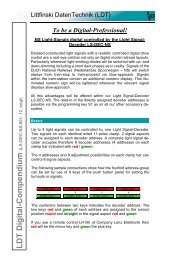
Light signal decoder - LDT
Light signal decoder - LDT
Light signal decoder - LDT

You also want an ePaper? Increase the reach of your titles
YUMPU automatically turns print PDFs into web optimized ePapers that Google loves.
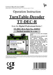
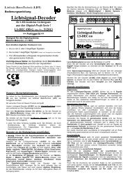
Littfinski DatenTechnik (<strong>LDT</strong>)<br />
Operating Instruction<br />
<strong>Light</strong> <strong>signal</strong> <strong>decoder</strong><br />
for light-<strong>signal</strong>s with LED<br />
from the Digital-Professional-Series !<br />
LS-DEC-DR-G Part-No.: 516013<br />
>> finished module in a case
1. Main- and Advance Signal:<br />
GE<br />
RT2<br />
WS<br />
GN<br />
RT1<br />
main <strong>signal</strong><br />
advance <strong>signal</strong><br />
Hl 13 Hl 3a / 3b Hl 10 Hl 7<br />
round/red/- round/red/- round/red/- round/red/-<br />
1 2 3 4<br />
straight/green/+ straight/green/+ straight/green/+ straight/green/+<br />
Hl 1 Hl 2 / 3a Hl 1 Hl 4<br />
2. Main-<strong>Light</strong> Signal:<br />
RT2<br />
WS<br />
GE2<br />
GN<br />
GE<br />
GN1<br />
WS<br />
RT1<br />
main-light <strong>signal</strong><br />
Hl 13 Hl 13<br />
round/red/- round/red/- round/red/- round/red/-<br />
1 2 3 4<br />
straight/green/+ straight/green/+ straight/green/+ straight/green/+<br />
Hl 13 + Ra 12 Hl 13<br />
Hl 12a / Hl 12b Hl 6a / Hl 6b<br />
round/red/- round/red/- round/red/- round/red/-<br />
1 2 3 4<br />
straight/green/+ straight/green/+ straight/green/+ straight/green/+<br />
Hl 9a / Hl 9b Hl 3a / Hl 3b<br />
Hl 11 / Hl 12a Hl 5 / Hl 6a<br />
round/red/- round/red/- round/red/- round/red/-<br />
1 2 3 4<br />
straight/green/+ straight/green/+ straight/green/+ straight/green/+<br />
Hl 8 / Hl 9a Hl 2 / Hl 3a<br />
Hl 10 Hl 4<br />
round/red/- round/red/- round/red/- round/red/-<br />
1 2 3 4<br />
straight/green/+ straight/green/+ straight/green/+ straight/green/+<br />
Hl 7 Hl 1<br />
Further sample connections are available at the internet on our Web-<br />
Site (www.ldt-infocenter.com) at the section “Sample Connections”.<br />
Additionally you can find detailed information about the <strong>Light</strong> <strong>signal</strong><strong>decoder</strong><br />
LS-DEC-DR at our Web site within the section “Digital-<br />
Compendium”.<br />
RT1<br />
GE1<br />
Programming the <strong>decoder</strong> address:<br />
• The jumper J3 has to be inserted for the programming of the<br />
<strong>decoder</strong> addresses.<br />
• Switch-on the power supply of your model rail way.<br />
• Activate the programming key S1.<br />
• At least two light emitting diodes on a <strong>signal</strong> connected to the<br />
left clamp block (on this <strong>decoder</strong> side is the programming key S1)<br />
will be automatically switched over every 1,5 seconds in a<br />
flashing mode. This indicates that the <strong>decoder</strong> is in the<br />
programming mode.<br />
• Press now one key of the fourfold address-group to be<br />
assigned to the left clamp block of the <strong>decoder</strong>. For programming<br />
the <strong>decoder</strong> address you can also release a turnout switch <strong>signal</strong><br />
via a personal computer.<br />
Remarks: The <strong>decoder</strong> addresses for magnet accessories also<br />
to be used for switching the <strong>signal</strong>-aspects are combined into<br />
groups of four. The address 1 to 4 will be the first group. The<br />
address 5 to 8 will be the second group etc. Each clamp block of a<br />
LS-DEC <strong>decoder</strong> can be assigned to any of these groups. It does<br />
not matter which of the eight possible keys used for programming<br />
will be activated. The <strong>decoder</strong> stores always the complete group of<br />
keys.<br />
If the <strong>Light</strong>-Signal <strong>decoder</strong> LS-DEC shall control main- and<br />
advance <strong>signal</strong>s or main-light <strong>signal</strong>s this has to be adjusted<br />
together with the <strong>decoder</strong> address. If you activate within the<br />
programming mode one key of the desired group of four keys<br />
designated for switching a turnout straight or a <strong>signal</strong> to green the<br />
<strong>decoder</strong> will be set for controlling of main- and advance <strong>signal</strong>s.<br />
GN1<br />
If you activate a key for switching a turnout round or a <strong>signal</strong> to red<br />
you have selected the option to switch main-light <strong>signal</strong>s. It is<br />
essential to activate for both programming settings (left and right<br />
clamp bar) both either a red or a green key.<br />
• If the <strong>decoder</strong> has recognized the assignment correctly the<br />
connected light emitting diode will flash a little faster. Afterwards<br />
the flashing slows down to the initial 1,5 seconds again.<br />
In case the <strong>decoder</strong> will not recognize the address it could be that<br />
the two digital information connections (clamp 2) are wrong<br />
connected. For testing this, switch off the power supply, exchange<br />
the connection on KL2 and start addressing again.<br />
• Press now the programming key S1 again. At least two light<br />
emitting diodes connected to the right clamp block will flash now.<br />
Repeat the programming for this clamp block as described above.<br />
• Now press the programming key S1 a third time for leaving the<br />
programming mode. All <strong>signal</strong>s will be automatically switched to<br />
STOP.<br />
Signal switching:<br />
The opposite sample connections show how the fourfold addressgroup<br />
can be set by use of 8 keys of the push button panel for setting<br />
the turnouts or <strong>signal</strong>s. Between each pair of keys are e.g. the<br />
addresses 1 to 4. The two keys red and green for each address are<br />
assigned to the turnout position round or straight respectively the<br />
corresponding <strong>signal</strong> aspect which is indicated above or below key.<br />
The actual address section is related to which fourfold addressgroup<br />
has been selected during the programming.<br />
If you use a remote control LH100 of Company Lenz Elektronik then<br />
red will be the minus key and green the plus key.<br />
If you have selected during programming the light-<strong>signal</strong> <strong>decoder</strong> for<br />
the switching of main- and advance <strong>signal</strong>s as shown at the upper<br />
draft you can switch for example with the address 1 and key green the<br />
main <strong>signal</strong> to proceed (HI 1).<br />
The light emitting diode marked with GN will now indicate this at the<br />
<strong>signal</strong>.<br />
If you have set the <strong>decoder</strong> during programming the addresses for<br />
switching main-light <strong>signal</strong>s you should refer to sample 2.<br />
For the main <strong>signal</strong> is it possible to set a total of 14 <strong>signal</strong> aspects.<br />
How to realize this with only 8 keys (4 addresses) shows the key<br />
occupation below the <strong>signal</strong>. After switching-on the main-light <strong>signal</strong><br />
shows HI 13. If now e.g. HI 1 shall be shown at first the address 4 with<br />
green key and then address 2 with green key shall be activated.<br />
Only bold framed keys are required for switching the <strong>signal</strong>.<br />
Is the main-light <strong>signal</strong> equipped with a substitute-red light emitting<br />
diode you can connect either the light emitting diode main-red or<br />
substitute-red to RT 1 of the clamp bar on the <strong>Light</strong>-<strong>signal</strong> <strong>decoder</strong>.<br />
<strong>Light</strong> bars:<br />
The light-<strong>signal</strong> <strong>decoder</strong> LS-DEC-DR supports as well light bars. You<br />
can decide if you connect the green light bar to indicate with HI 2<br />
(travel speed 100km/h) or leave it to indicate with HI 3a (travel speed<br />
40km/h). Just as well you can connect the yellow bar to indicate with<br />
HI 3b (travel speed 60km/h) or leave it to indicate with HI 3a (travel<br />
speed 40km/h).<br />
If your DR-<strong>signal</strong> contains light bars with serial light emitting diodes<br />
(models of manufacturer Erbert) you require the adapter Adap-LS.<br />
Attention:<br />
The <strong>Light</strong> <strong>signal</strong> <strong>decoder</strong> LS-DEC switches the <strong>signal</strong> aspects not just<br />
on and off but is dimming the light emitting diodes realistic up and<br />
down. Even between the <strong>signal</strong> aspects a short off-phase is provided.<br />
Further digital commands received during this switch-over-time of about<br />
0,4 seconds will not be taken up from the <strong>decoder</strong>. Please take care<br />
that the switching-commands are not in a to fast sequence. The<br />
impression is absolutely realistic if the switching is considerable slow.<br />
If the jumper J3 will be removed after programming of the <strong>decoder</strong><br />
addresses the memory storage of the <strong>Light</strong> <strong>signal</strong> <strong>decoder</strong> LS-DEC<br />
will be protected against any alteration.<br />
Made in Europe by<br />
Littfinski DatenTechnik (<strong>LDT</strong>)<br />
Kleiner Ring 9<br />
D-25492 Heist/Germany<br />
Phone: 0049 4122 / 977 381<br />
Fax: 0049 4122 / 977 382<br />
Internet: http://www.ldt-infocenter.com<br />
Subject to technical changes and errors. © 11/2012 by <strong>LDT</strong><br />
Märklin and Motorola are registered trademarks.