With DVD: The new 42-5 - Putzmeister
With DVD: The new 42-5 - Putzmeister
With DVD: The new 42-5 - Putzmeister

Create successful ePaper yourself
Turn your PDF publications into a flip-book with our unique Google optimized e-Paper software.
1<br />
<strong>The</strong> magazine by <strong>Putzmeister</strong> Holding GmbH 81<br />
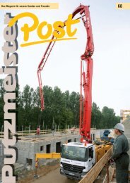
<strong>With</strong> <strong>DVD</strong>:<br />
<strong>The</strong> <strong>new</strong> <strong>42</strong>-5<br />
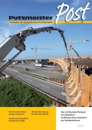
New runway for<br />
Germany's largest<br />
airport: Large boom<br />
pumps concreted<br />
taxiway bridge<br />
New pumping record in<br />
North India's Himalaya<br />
New standards for<br />
truck-mounted concrete<br />
pumps: <strong>42</strong>-5<br />
New railway tunnel in<br />
Vienna: Long distance<br />
concrete delivery in the<br />
Lainzer Tunnel<br />
PM 4377 GB
Content<br />
Content<br />
2 4<br />
Title story<br />
Lainzer Tunnel in Vienna:<br />
Concrete placed over 1400 m distance 4<br />
<strong>The</strong> <strong>new</strong> <strong>42</strong>-5<br />
WELCOME<br />
WELCOME<br />
Revolutionary!<br />
<strong>The</strong> next generation of the <strong>42</strong>-5 8<br />
On site<br />
Airport Frankfurt am Main:<br />
Large boom truck-mounted concrete pumps placing<br />
concrete for taxiway bridges of the runway North East 14<br />
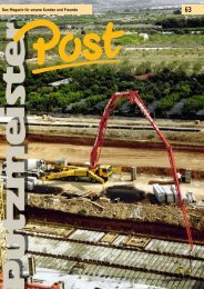
Uttrakhand / North India:<br />
BSA pumps Indian long distance record<br />
of concrete placement! 20<br />
4<br />
Tunnel concreting in the<br />
Lainzer Tunnel, Vienna<br />
8<br />
All <strong>new</strong>:<br />
<strong>The</strong> next generation<br />
of the <strong>42</strong>-5<br />
3 5<br />
WELCOME<br />
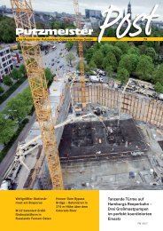
In October, we will be presenting<br />
the <strong>new</strong> <strong>42</strong>-5 in a<br />
roadshow at the following<br />
locations, with each show<br />
taking place<br />
from 11 a.m. to 5 p.m.<br />
New pre-cast concrete plant for wind power systems:<br />
Analysis of concrete mix with the rheometer 24<br />
Tue 4th Oct.<br />
<strong>Putzmeister</strong> Aichtal<br />
50 Questions<br />
What does <strong>Putzmeister</strong> do against wear and tear? 12<br />
<strong>Putzmeister</strong> Solid Pumps<br />
Wed 5th Oct.<br />
Frankfurt Service Centre<br />
Thu 6th Oct.<br />
Essen Service Centre<br />
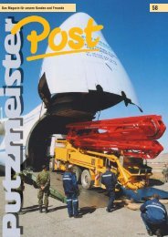
Ship and offshore applications<br />
Drill cuttings storage and pumping system<br />
on Norwegian ships 26<br />
In brief<br />
Caution: Snappy ad! 28<br />
M 52 approaching the Hoover Dam bypass bridge 29<br />
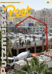
Large project in Saudi Arabia:<br />
King Abdullah Financial District 30<br />
Telebelt reduces the costs of placing mass<br />
concrete in Chinese shipyard 31<br />
Photo credits 2<br />
Imprint 3<br />
14<br />
Large concreting work<br />
of taxiway bridges at<br />
the airport Frankfurt<br />
Photo credits:<br />
Unless indicated otherwise, all illustrations are copyright<br />
<strong>Putzmeister</strong> Holding GmbH.<br />
18: Europe_topography_map_en, Wikimedia Commons,<br />
licensed under CreativeCommons license bysa-3.0,<br />
San Jose · 3, 28 - 35, 37: Die Pumas · 36:<br />
Fraport AG · 39: Public Domain, SKopp · 47: India_<br />
uttarakhand_locator_map, Wikimedia Commons,<br />
licensed under CreativeCommons license by-sa-3.0,<br />
PlaneMad/Wikipedia · 48: bhagirathi_river_map,<br />
Wikimedia Commons, licensed under CreativeCommons<br />
license by-sa-3.0, Fowler&Fowler · 49: nanda_<br />
devi2, Wikimedia Commons, licensed under CreativeCommons<br />
license by-sa-2.0, Michael Scalet · 53:<br />
strabag_gelände_luftbild, www.offshore-basis.de<br />
· 54: barrow_offshore_wind_turbines, Wikimedia<br />
Commons, licensed under CreativeCommons license<br />
by-sa-3.0, Andy Dingley · 55 - 57, 59 - 60: <strong>Putzmeister</strong><br />
Solid Pumps GmbH · 58: Valkyrie_by_Robert_Engels_(black_and_white).png,<br />
Public Domain<br />
· 64, 65: www.kingabdullahfinancialdistrict.com<br />
Imprint:<br />
Editor:<br />
<strong>Putzmeister</strong> Holding GmbH<br />
Max-Eyth-Str. 10<br />
72631 Aichtal · Germany<br />
Editorial department/Layout/DTP:<br />
Petra Montag<br />
<strong>Putzmeister</strong> Holding GmbH<br />
Print:<br />
Offizin Scheufele GmbH & Co. KG<br />
Tränkestr. 17<br />
70597 Stuttgart · Germany<br />
Indian record in<br />
long distance pump-<br />
20ing of concrete!<br />
All rights and technical amendments<br />
reserved.<br />
Although content is checked carefully,<br />
we accept no liability for sites to<br />
which links are given. <strong>The</strong> operators of<br />
extern al websites are solely liable for<br />
their content.<br />
Some of the illustrations show special<br />
machine variants and snapshots which<br />
do not always comply with the regulations<br />
of the Industrial Employers’ Liability<br />
Insurance Association.<br />
© by <strong>Putzmeister</strong> Holding GmbH 2011<br />
Printed in Germany (41109)<br />
Sat 8th Oct.<br />
Hamburg Service Centre<br />
Mon 10th Oct.<br />
Berlin Service Centre<br />
Wed 12th Oct.<br />
Gera Service Centre<br />
Fri 14th Oct.<br />
Munich Service Centre<br />
2 PM 4377 GB PM 4377 GB 3
Rubrik Title story<br />
Title Rubrik story<br />
Lainzer Tunnel in Vienna:<br />
Concrete placed over 1400 m distance<br />
<strong>The</strong> Lainzer Tunnel is a railway tunnel in<br />
Vienna that is 12.8 km long and, from<br />
December 2012, will connect the Westbahn<br />
(west ern railway) with the Südbahn<br />
(southern railway) and the Donauländebahn<br />
railway. <strong>The</strong> purpose of this plan is<br />
to increase the capacity of the east-west<br />
transit system.<br />
<strong>The</strong> tunnel starts at the Wien-Hadersdorf<br />
station and runs below the Lainzer Tiergarten<br />
to the west of Vienna, from Speising<br />
close to the existing junction line<br />
and, at its mouth, joins the Südbahn line<br />
before Wien-Meidling station and the<br />
Donauländebahn line in Altmannsdorf. It<br />
is part of the Westbahn and the European<br />
High-Speed Line be tween Paris – Budapest.<br />
<strong>The</strong> LT 31 consortium (HOCHTIEF<br />
Construction AG, Alpine Bau GmbH and<br />
Beton- und Monierbau GmbH), under<br />
the leadership of HOCHTIEF Construction<br />
AG, was commis sioned by the ÖBB-<br />
Infrastruktur Bau AG to construct a main<br />
section of the Lainzer Tunnel.<br />
To execute the inner lining in built-up<br />
areas, from October 2008, the concrete<br />
for separating the underground transport<br />
traffic from the above-ground transport<br />
traffic was pumped through a permanently<br />
installed delivery line, measuring<br />
be tween 300 m and 1400 m in length,<br />
from the concrete mixing plant at the<br />
construction site directly to the placement<br />
site.<br />
<strong>The</strong> concrete mixture was designed to<br />
meet specific structural and pumping requirements<br />
and was subject to continuous<br />
monitoring from a concrete technology<br />
perspective throughout the duration<br />
of the construction project.<br />
6<br />
<strong>The</strong> interior construction of the tunnel<br />
was performed using a watertight concrete<br />
inner shell (d>=50 cm), with PP<br />
fibres added to the concrete in order to<br />
improve its resistance to fire. In addi tion,<br />
the inner shell was designed with an<br />
8 cm enlarged concrete covering of the<br />
reinforcement (reinforcement proportion<br />
of the tunnel lining is approx. 85 kg/m³<br />
of concrete).<br />
<strong>The</strong> formwork carriages for each segment<br />
of the tunnel were 10 m in length,<br />
result ing in an installation quantity of<br />
approx. 150 m³ of concrete for the tunnel<br />
lining of each concreting section and of<br />
90 m³ for the base.<br />
<strong>The</strong> interior work had already commenced<br />
in parallel to the headwork, and<br />
the concrete was fed via two vertical<br />
starting shafts. It was therefore decided<br />
at an early stage to supply the concrete<br />
for the formwork carriages using a stationary<br />
concreting facility – consisting of a<br />
stationary concrete pump and a specially<br />
designed delivery line. As a result of the<br />
positive experience gained from the beginning,<br />
this form of concreting logis tics<br />
was maintained even after the headwork<br />
was completed. In the construction phases<br />
S and M, one delivery line each was<br />
available for the base and the arch for<br />
the concreting logistics. As a result, up<br />
to four formwork carriages could be filled<br />
with concrete in parallel. In this way,<br />
concreting outputs of up to 500 m 3 per<br />
day with reinforcement work running in<br />
parallel could be achieved. This had the<br />
positive effect that restrictions and obstructions<br />
in the tunnel could be elim-<br />
ÄÄFacts and figures<br />
Total figures for the Lainzer Tunnel<br />
Line length<br />
12.8 km<br />
Tunnel length<br />
12.3 km<br />
Total length of track reconstruction<br />
and construction<br />
25.3 km<br />
Civil engineering works<br />
• 7 approach shafts<br />
• 4 entrances<br />
• 28 emergency shafts<br />
• 4 factory buildings<br />
• 4 construction and reconstruction<br />
of S-Bahn stations<br />
• 6 street crossings<br />
• 10 rail crossings<br />
• 5 pedestrian and bicycle<br />
crossings<br />
• 2 river crossings<br />
• 3 installation collectors<br />
LT 31 Maxing construction section<br />
Length<br />
approx. 3,050 m<br />
Overlying<br />
6 – 26 m<br />
Tunnel width<br />
13.60 m<br />
Tunnel height<br />
12.56 m<br />
Starting and hauling shafts<br />
Depth<br />
approx. 30 m<br />
Length<br />
approx. 24 m<br />
Maximum width approx. 17 m<br />
Minimum width approx. 10 m<br />
7<br />
t <strong>The</strong> separating film can be seen in front of the arch formwork carriage. It separates<br />
the inner and outer shells of the tunnel. This separating film is used to secure the steel<br />
reinforcement for the final concrete inner shell.<br />
4 PM 4377 GB PM 4377 GB 5
Title story<br />
Title story<br />
8<br />
composition table), had to meet the<br />
requirements for a construction that is<br />
dense (WDI), fire-resistant (BBG) and<br />
self-compacting (SCC), and it also had<br />
to represent an economically attractive<br />
solution for the execution. From a structural<br />
point of view, a grading curve with<br />
an increased sand content (70 %) and<br />
a reduced maximum particle size GK 16<br />
mm round grain was selected. <strong>With</strong> a<br />
binder content of 280 kg/m³ CEM I <strong>42</strong>,5<br />
R (C3A-free) and the addition of a type<br />
I additive (AHWZ - Effective Additives<br />
Prepared Hydraulically) of 170 kg/m³,<br />
a fines content of over 540 kg/m³ was<br />
prepared.<br />
PP fibres with a short fibre length<br />
(3 mm) were added in the dosage<br />
describ ed in the table. Consistency tests<br />
on the fresh concrete showed a diameter<br />
of concrete flow of 58 cm with very good<br />
fluidity and sufficient self-compaction.<br />
Concrete composition WDI / BBG / SCC<br />
Base material<br />
Quantity<br />
Cement CEM I <strong>42</strong>,5R HS C3A-frei 280 kg/m 3<br />
Fluamix C 170 kg/m 3<br />
Chargeable binder 388 kg/m 3<br />
Water in scc. with batch report 185 kg/m 3<br />
LZF/LZ51 1)<br />
LP 100<br />
Stabilisator Strong<br />
5.6 kg/m 3 / 1.24 % from cement amount<br />
0.18 kg/m 3 / 0.04 % from cement amount<br />
1.6 kg/m 3 / 0.36 % from cement amount<br />
Fibes PM 3/15 2) 1.2 kg/m 3<br />
Stone particles (dry) 1706<br />
0/4 70 %<br />
4/8 10 %<br />
8/16 20 %<br />
1) <strong>The</strong> LZF/LZ51 was apportioned in the ratio 70:30.<br />
2) <strong>The</strong> fibres PM 3/15 were added to the forced mixer by hand.<br />
In the next part of the construction project,<br />
<strong>Putzmeister</strong> systems engineering<br />
was also used for construction phases S<br />
and W, with a total of six stationary concrete<br />
pumps, delivery lines and functional<br />
elements. This was not just because of<br />
the design of stationary concrete pumping<br />
technology which balances economical<br />
and technical factors but also because<br />
of the outstanding local-service<br />
provided by the Austrian <strong>Putzmeister</strong><br />
dealer, Hans Eibinger GmbH. n<br />
9<br />
p A hose was branched off from the delivery line and fed the BSA 1408 E at the arch formwork carriage<br />
inated by simultaneous reinforcement<br />
and concrete transport. It was possible<br />
to speed up the construction sequence<br />
considerably: Six months‘ time saved in<br />
comparison to transport via mixers.<br />
Concreting<br />
A stationary concrete pump BSA 2109 H<br />
E (later a BSA 2107 SHP E) pumped concrete<br />
via a delivery line that was permanently<br />
installed in the tunnel from above<br />
ground to the arch and base car riages,<br />
which were a maximum of approx.<br />
1,400 m away.<br />
At times, the base concreting ran ahead<br />
of the arch by up to 600 m. To feed the<br />
arch formwork carriage, the delivery line<br />
was branched off at an appropriate point<br />
and a delivery hose was used to guide<br />
the concrete into the stationary relay<br />
pump BSA 1408 E directly at the formwork<br />
carriage. Short distances between<br />
the crew of the formwork carriage and<br />
the pump machine operator prevented<br />
compressive stress peaks in the formwork<br />
carriage.<br />
A P 715 fine concrete pump was available<br />
for the concreting of the cross cuts.<br />
Cleaning<br />
<strong>The</strong> DN 150 delivery line was cleaned<br />
by using water to force the concrete residue<br />
out in a „forwards“ direction. Depending<br />
on the length of the line, this<br />
work was carried out by a BSA 2109 H<br />
D or a BSA 1409 D. „Forwards“ water<br />
cleaning is usually selected for relatively<br />
long concrete delivery lines in order to<br />
prevent large quantities of concrete residue<br />
from forming. A replacement pipe<br />
is then equipped with a media separation<br />
system in order to separate the concrete<br />
from the water when the concrete<br />
residue is being forced out and, after<br />
the concreting process is complete, it is<br />
put in use directly behind the stationary<br />
pump. <strong>The</strong> replacement pipe mentioned<br />
above is usually fitted with a combinat-<br />
ion of sponge balls and wash-out pigs.<br />
Suitable media separation systems must<br />
be configured depending on the concrete<br />
delivery line installation. <strong>The</strong>y are an<br />
important part of the delivery line planning<br />
to ensure the availability of the stationary<br />
concrete delivery facility.<br />
<strong>The</strong> BSA 2109 H E (from April 2009, this<br />
is a modified BSA 2107 SHP E) pumped<br />
approx. 28 m 3 of concrete per hour over<br />
the distance mentioned above to the<br />
arch or base formwork carriage.<br />
Concrete<br />
A tunnel section of 20 tunnel segments,<br />
each 10 m long, was produced from<br />
self-compacting concrete (SCC). For this<br />
purpose, the Pöyry Infra GmbH (MVA<br />
Strass) laboratory developed a concrete<br />
mixture that was specifically formulated<br />
for this delivery process.<br />
<strong>The</strong> mixture breakdown of the SCC/<br />
WDI/BBG concrete (see the concrete<br />
u <strong>The</strong> formwork carriage at the front<br />
is the base formwork carriage. <strong>The</strong> prepared<br />
steel reinforcement can be seen at<br />
the end of this carriage.<br />
u <strong>The</strong> formwork elements are filled<br />
using a type of rotary distributor. <strong>The</strong><br />
BSA 2109 H E directly supplies this with<br />
concrete.<br />
10<br />
6 PM 4377 GB PM 4377 GB 7
<strong>The</strong> <strong>new</strong> <strong>42</strong>-5 <strong>The</strong> <strong>new</strong> <strong>42</strong>-5<br />
Revolutionary!<br />
<strong>The</strong> next generation of the <strong>42</strong>-5<br />
11 12<br />
Fifty years of experience in the development<br />
of concrete pumps means innovations<br />
time and again. <strong>The</strong>se innovations<br />
revolutionise the pumping and delivering<br />
of concrete. This is always based on<br />
the tried and tested, robust concrete<br />
pumps from <strong>Putzmeister</strong>, which are constantly<br />
being improved upon and adapted<br />
to meet modern demands.<br />
<strong>With</strong> the <strong>42</strong>-5 from the <strong>new</strong> generation,<br />
we have gone one step further: We took<br />
the basic idea and then completely rethought<br />
and redesigned it. Countless<br />
suggestions from customers, operators,<br />
suppliers and <strong>Putzmeister</strong> employees<br />
have flowed into the project.<br />
From this emerged an innovation that is<br />
setting standards on the market.<br />
No fear of the scales<br />
<strong>The</strong> resulting <strong>new</strong> design, from the boom<br />
tip to the base structure, makes a gross<br />
weight of less than 32 t pos sible, incl.<br />
sufficient reserves for payload, equipment,<br />
water and fuel.<br />
Better in every respect<br />
<strong>The</strong> concept for the <strong>new</strong> <strong>42</strong>-5 was completely<br />
revised and scrutinised, always<br />
with the operator in mind. <strong>The</strong> <strong>42</strong>-5 has<br />
gained increasing importance when it<br />
comes to operation, safety, operat ing<br />
costs and service in particular.<br />
Calculated and tested<br />
All essential components have been calculated<br />
using modern methods. Extensive<br />
field tests verify the maturity and reliability<br />
of the machine.<br />
p Service-optimised and easy to retrofit thanks to the screw-fitted pipe bracket and<br />
exclusive use of standard delivery line bends. For example, only three types of standard<br />
delivery line bends are now used, whereas seven types were used in the past.<br />
p <strong>The</strong> fluid cooler that is integrated into<br />
the support leg ensures optimal cool ing<br />
of the hydraulic fluid, even in OSS operation.<br />
www.the<strong>new</strong><strong>42</strong>-5.com<br />
13<br />
8 PM 4377 GB PM 4377 GB 9
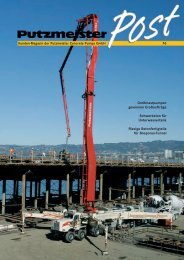
18<br />
<strong>The</strong> <strong>new</strong> <strong>42</strong>-5 <strong>The</strong> <strong>new</strong> <strong>42</strong>-5<br />
p <strong>The</strong> <strong>new</strong> Ergonic Graphic Display clearly displays all of the relevant data for the<br />
machine. Shown here: Overview of the system status and fault management<br />
14<br />
15<br />
Between June and the end of October<br />
2011, two machines from the <strong>new</strong> <strong>42</strong>-5<br />
series are being used almost every day.<br />
<strong>The</strong> tours are passing through South<br />
Tyrol, Switzerland, Austria, Germany,<br />
Finland, Sweden, Denmark and Luxembourg.<br />
From September, a <strong>42</strong>-5 will also be on<br />
the road to construction sites in the hot<br />
climate of Qatar. This is a particular hardness<br />
test for the machine because, in<br />
addition to the demanding climate conditions,<br />
very difficult concrete mixes will<br />
also put to the test the machine's suitability<br />
for daily use.<br />
Pay no attention to external conditions.<br />
During a field test, all types of construction<br />
sites are in operation: Bottom plates,<br />
walls, decks, tunnels, etc. Only the width<br />
testing finally shows the machine's<br />
comprehensive reliability when used in<br />
pract ice at a later point.<br />
All field test machines are equipped with<br />
a wide range of sensors which monitor<br />
the hydraulic system and many other<br />
functions. Regular inspections deliver<br />
results mainly regarding the mechanical<br />
condition of the machines.<br />
This and, most importantly, the feedback<br />
from the machine operators are<br />
incorporated in the optimisation phase,<br />
with the aim of being able to offer a product<br />
at the start of series production that<br />
has been completely field-tested. n<br />
<strong>The</strong> field test with<br />
two <strong>new</strong> <strong>42</strong>-5:<br />
On the road for<br />
five months<br />
q Uwe Fischer from<br />
"a3 Beton" went for a<br />
test drive with the <strong>new</strong><br />
<strong>42</strong>-5 in Switzerland<br />
20<br />
ÄÄWhat do the people who<br />
work with the <strong>new</strong> <strong>42</strong>-5<br />
have to say?<br />
"I particularly like the steady boom –<br />
also, the machine as whole works very<br />
smooth during pumping."<br />
Uwe Fischer, a3 Beton, Switzerland<br />
"<strong>The</strong> machine moves with agility on<br />
our windy, mountainous roads. <strong>The</strong><br />
low weight and the short wheelbase<br />
are perfect for this. <strong>Putzmeister</strong> has<br />
done a very good job – you can sense<br />
the high quality of the machine."<br />
Hans-Karl Huber, Rienz Beton, Italy<br />
"I like my old <strong>42</strong>-5, but the boom on the<br />
<strong>new</strong> <strong>42</strong>-5 moves superbly. Above all, it<br />
responds really well to the controls."<br />
Ville Sinko, Transsinko Oy, Finland<br />
"I really like the machine – and not<br />
just the look of it. It is somehow elegant.<br />
All of the parts are easily accessible<br />
and <strong>Putzmeister</strong> even had us<br />
machine operators in mind with their<br />
accessories. I would love to be able to<br />
keep this test machine for myself."<br />
19<br />
Volkmar Spies, Die Pumas, Germany<br />
22<br />
p Water tank with 800 l capacity (as standard)<br />
16 17<br />
21<br />
p <strong>The</strong> sponge ball is always accessible in<br />
the container.<br />
p Delivery notes are stored securely in<br />
the watertight, lockable docubox.<br />
10 PM 4377 GB PM 4377 GB 11
50 Questions 50 Questions<br />
Technology · Question 28<br />
What does <strong>Putzmeister</strong> do<br />
against wear and tear?<br />
23<br />
24 25 26<br />
Chippings arise when planing. And<br />
wherever concrete flows, scratches arise<br />
from stones - extra hard coatings and<br />
double-walled conveying pipes ensure<br />
that the wear and tear is kept within reasonable<br />
limits.<br />
<strong>The</strong> material suffers wear where concrete<br />
flows along machine elements – in the<br />
concrete hopper with pipe branching, at<br />
the mixer, in the pump and especially in<br />
the conveying lines. This is what we call<br />
sliding abrasion.<br />
"How many cubic metres does your line<br />
hold?", customers ask regularly. That depends<br />
on what type of concrete is used<br />
and how much is being conveyed. Wear<br />
mainly depends on the type and distribution<br />
of the aggregates (particle-size<br />
distribution curve), the proportion of<br />
the binding agent (cement and/or quick<br />
ash), the water/cement ratio (water/cement<br />
factor), as well as the shape, hardness<br />
and porosity of the aggregates.<br />
In Germany alone the degree of hardness<br />
of the aggregates differs depending<br />
on the region between factor 15 – 20.<br />
<strong>With</strong> so-called "ball bearing concrete"<br />
compris ing soft rounded gravel, one<br />
can pump a good 60,000 cubic metres<br />
of concrete using typical pipe lines at<br />
a conveying quantity of 60 - 70 cubic<br />
metres per hour. If one pumps concrete<br />
with extremely hard, broken material<br />
in the same line, then the concrete line<br />
only stands approx. 4,000 cubic metres.<br />
High-tech metallurgy controls<br />
wear and tear<br />
To minimise sliding abrasion, <strong>Putzmeister</strong><br />
concentrated on specially hardened<br />
conveying pipes from early on. Today<br />
there are conveying lines with two layers.<br />
<strong>The</strong>y comprise an outer pipe and an<br />
inner pipe made from highly resistant<br />
material.<br />
Armoured elements last longer<br />
<strong>The</strong> components of the concrete pump<br />
are also armoured: A multi-layer special<br />
coating made from chrome protects the<br />
conveying cylinders which are particularly<br />
prone to wear and tear. <strong>With</strong> this<br />
coating <strong>Putzmeister</strong> guarantees a pumping<br />
quantity of at least 100,000 cubic<br />
metres – also for the most aggressive concrete<br />
mixes. <strong>The</strong> pipe branching where<br />
the cross-section of the concrete flow is<br />
reduced and wear and tear is particularly<br />
high, comprises a highly resistant<br />
special cast steel or is armoured with<br />
highly resistant steel facing.<br />
Data and technology enable<br />
the wear and tear to be calculated<br />
<strong>Putzmeister</strong> developed a database to<br />
calculate the wear and tear. It contains<br />
information on the wear properties of<br />
aggregates in many regions all over the<br />
world. As the wear is also dependent on<br />
the pumping speed, the concrete pump<br />
measures the strokes per operating time<br />
and thus calculates the average pumping<br />
performance. Reliable statements on the<br />
wear-resistance of components can therefore<br />
be made – provided the customer<br />
always pumps concrete with the same<br />
wear properties.<br />
Leader thanks to low wear costs<br />
<strong>Putzmeister</strong> products suffer notably less<br />
wear and tear thanks to the implementation<br />
of many measures. <strong>The</strong> wear costs<br />
per cubic metre of concrete amount to<br />
40 – 60 cent for the entire machine.<br />
Many customers undercut this value by<br />
pump ing slower, resulting in reductions<br />
in wear and tear and energy consumption.<br />
In the meantime, the computeraided<br />
concrete pump control supports<br />
operat ors in the wear-reducing operation<br />
of machines with the "Ergonic® Output<br />
Control (EOC)" function for example.<br />
Thanks to the wear measurement data<br />
and the tele-service the wear and tear<br />
can also be monitored remotely. <strong>The</strong><br />
data shows when it is time to replace a<br />
part. <strong>The</strong> Ergonic® control systems from<br />
<strong>Putzmeister</strong> thus permit preventative<br />
maintenance. n<br />
28<br />
u Intensive wear or not?<br />
Examples for concrete mixes from four<br />
countries: <strong>The</strong> particle-size distribution<br />
curves of aggregates are shown here.<br />
<strong>The</strong> more adverse the particle-size distribution<br />
curve and the lower the water/<br />
cement factor, the greater the wear and<br />
tear. This effect is further influenced by<br />
the surface structure of the aggregates.<br />
From left to right: Rounded pebbles<br />
from Austria; Broken stones from India<br />
and Dubai; <strong>The</strong> samples from Turkey<br />
on the far right have really sharp edges<br />
and are hard. <strong>The</strong> aggregates also differ<br />
within a country from a region to region.<br />
For example: Hard metal wear parts<br />
p Hard metal wear plates with two to<br />
four times longer service life compared<br />
to DURO 22 (standard)<br />
27<br />
<strong>The</strong> parts of a concrete pump which<br />
are in direct contact with the generally<br />
strong abrasive medium are subject to a<br />
variety of wear conditions:<br />
• Sliding abrasion on both contact<br />
surfaces of the wear parts<br />
• Blast jet wear on the outer edges<br />
of the wear ring and inner edges<br />
of openings on the spectacle wear<br />
plate<br />
• Impact stress at the parting plane,<br />
between the spectacle wear plate<br />
and wear ring<br />
• Flow abrasion on openings of the<br />
spectacle wear plate and ring<br />
Hard metal wear parts increase the<br />
service life of the concrete pumps<br />
Hard metal wear parts comprise a basic<br />
body (structural steel) and an approx.<br />
5 mm thick hard metal wear layer.<br />
Hard metal wear parts have been<br />
available from <strong>Putzmeister</strong> for approx.<br />
20 years.<br />
Different versions of hard metal wear<br />
plates have been developed and used<br />
from years of experiences with extreme<br />
applications in concrete conveying<br />
(e.g. Burj Khalifa).<br />
12 PM 4377 GB PM 4377 GB 13
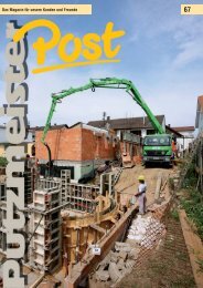
On site<br />
On site<br />
28<br />
29<br />
M 58-5<br />
M 62-6 M 58-5<br />
M 62-6<br />
M 52-5<br />
RV 10<br />
M 63-5<br />
M 58-5 M 58-5 M 63-5<br />
Expansion at<br />
Frankfurt Airport:<br />
Large concreting work<br />
of taxiway bridges for the<br />
<strong>new</strong> North West runway<br />
<strong>The</strong> precise planning of the locations was fundamental so that the work areas of the large boom truck-mounted concrete pumps<br />
could be met. A M 58-5 and the M 62-6 were used on the north side and a second M 58-5 and a M 63-5 were on the south of the<br />
taxiway bridge.<br />
30<br />
DIE PUMAS Betonförderung GmbH & Co.<br />
KG is domiciled in the Rhine Main area<br />
with 30 truck-mounted concrete pumps<br />
with boom sizes of 24 to 63 m and stationary<br />
concrete distributing systems.<br />
Some of the longest distributing booms<br />
of PUMAS were used in August and September<br />
2010 in the large concreting work<br />
on the taxiway bridges at the Rhine Main<br />
Airport.<br />
<strong>The</strong> two taxiway bridges lead over the<br />
motorway and ICE line and connect the<br />
<strong>new</strong> North West runway 07L/25R to the<br />
current airfield. <strong>The</strong> <strong>new</strong> landing strip<br />
should be in operation for the 2011/12<br />
winter flight schedule. <strong>The</strong> first sod was<br />
turned in May 2009.<br />
West taxiway bridge –<br />
concreting August 2010<br />
<strong>The</strong> West bridge was able to be concreted<br />
efficiently and on schedule thanks<br />
to the exact planning of the locations<br />
by four <strong>Putzmeister</strong> large boom pumps.<br />
<strong>The</strong> superstructure was tackled with a<br />
M 63-5, a M 62-6 and two M 58-5 on<br />
20.08.2010 at approx. 20:00. <strong>With</strong>in 20<br />
hours 3,240 m³ of concrete was placed,<br />
which was made available in due time<br />
by the suppliers Sehring Beton GmbH &<br />
Co. KG.<br />
14 PM 4377 GB PM 4377 GB 15
On site<br />
On site<br />
31 32<br />
p <strong>The</strong> second machine on the south side, a M 58-5, had to be set up in the crane runway.<br />
East taxiway bridge –<br />
concreting September 2010<br />
After weeks of planning, the superstructure<br />
of the East taxiway bridge was concreted<br />
on 17.09.2010. A M 62-6, a M 58-5<br />
and a M 52-5 were used on the north<br />
side, as well as a M 63-5 and M 58-5 on<br />
the south.<br />
<strong>The</strong> superstructure with a width (E-W)<br />
of 345 m and a depth (N-S) of 91.5 m<br />
was divided into three concreting phases.<br />
Work began on the deepest part of<br />
the structure where the ICE line and<br />
both sides of the A3 motorway run.<br />
In the planning stage an placing period<br />
of 61.5 hours and a volume of 10,100<br />
m³ were assumed. <strong>The</strong> guarantee of an<br />
uninterrupted concrete supply from four<br />
placing crews by the concrete pumps<br />
from PUMAS was the main requirement<br />
for the possible first smooth concreting<br />
of almost 19,000 m².<br />
As despite the use of large boom pumps<br />
there was still a gap in the work areas of<br />
the placing booms, a rotary distributor<br />
p Neat parking: <strong>The</strong> M 52-5 found a suitable and secure installation site at the ICE line thanks to OSS<br />
33<br />
16 PM 4377 GB PM 4377 GB 17
On site<br />
On site<br />
34<br />
ÄÄExpansion for more flights at<br />
Europe's third largest airport<br />
(Source: Ausbau Aktuell, March/2011)<br />
In January 2011 the focus was on the<br />
excavation work for the dams for the<br />
taxiway bridges. To avoid pressure<br />
from the dams on the abutment walls<br />
of the taxiway bridges, which lead over<br />
the motorway and ICE line, so-called<br />
earth pressure traps were positioned.<br />
<strong>The</strong> concreting work for the 45 m wide<br />
and 2,800 m long runway is contin ued.<br />
<strong>The</strong> "completed" ones began with the<br />
concreting of two layers, each 11.25 m<br />
wide, in order to complete the missing<br />
part within 24 hours. <strong>The</strong> concreting<br />
work for the flight operation areas<br />
(runway and landing strips) will be<br />
completed by the end of May 2011. As<br />
soon as the work on the dams is complete,<br />
concrete will also be applied to<br />
the taxiway bridges. <strong>The</strong> aim is to also<br />
complete the full five bridge structures<br />
by May.<br />
<strong>The</strong> commercial airport Frankfurt am<br />
Main is by far Germany's largest airport<br />
and, at the same time, is one of the<br />
world's most important aviation hubs.<br />
Measured in terms of passenger figures<br />
it is the third largest airport in Europe after<br />
London-Heathrow and Paris-Charles<br />
de Gaulle and is number 9 in the world.<br />
After the airport in Paris, it has the second<br />
largest volume of cargo out of all<br />
European airports.<br />
<strong>The</strong> <strong>new</strong> runway should make possible<br />
a coordination benchmark figure of 126<br />
flights per hour at the airport in Frankfurt.<br />
q Graphic of the <strong>new</strong> runway 07L/25R with the two taxiway bridges<br />
36<br />
ÄÄwww.ausbau.fraport.de<br />
35<br />
p <strong>The</strong> M 63-5 also mastered this critical<br />
part of the concreting over the lane of<br />
the A3 motorway reliably and in a total<br />
of 34 hours!<br />
37<br />
p "Approach" of the rotary distributor<br />
RV 10, which further extended the working<br />
area of the M 58-5 in the centre of<br />
the taxiway bridge at the east.<br />
RV 10 was also used. This was used only<br />
at the start for 150 m³. All other areas<br />
could be reached directly by the booms<br />
of the truck-mounted concrete pumps.<br />
<strong>The</strong> RV 10 was fed by the M 58-5 on the<br />
north side of the taxiway bridge.<br />
<strong>The</strong> M 63-5 was assembled directly on<br />
the motorway of the A3 motorway heading<br />
toward Frankfurt and had to convey<br />
the concrete over the lanes onto the<br />
bridge. This called for the highest safety<br />
requirements. For this reason the complete<br />
piping of the machine was replaced<br />
before the commencement of the work.<br />
A fifth concrete pump, a M 52-5, was<br />
assembled north of the bridge between<br />
the ICE line and the A3 motorway in the<br />
direction of Cologne. It connected directly<br />
at the work area of the M 58-5 in an<br />
eastwards direction.<br />
After almost 20 hours and 3,700 m³ of<br />
concrete the first section of the superstructure<br />
was concreted.<br />
<strong>The</strong> concrete pumps were able to be used<br />
again without a location change for the<br />
start of the second section. <strong>The</strong> mid-section<br />
of the bridge concreted in the first<br />
section was finished with power trowels<br />
in the intermediate stage. Eventually<br />
after 46 hours and approx. 8,200 m³<br />
the booms of the concrete pumps reached<br />
their final locations. n<br />
18 PM 4377 GB PM 4377 GB 19
On site<br />
On site<br />
40<br />
38<br />
39<br />
Uttarakhand / North India:<br />
1100 m – <strong>new</strong> Indian<br />
record in long-distance<br />
concrete pumping!<br />
p Placing of the concrete in the casings at the tunnel walls to support the roof<br />
q <strong>The</strong> <strong>Putzmeister</strong> project team after<br />
the successful concreting<br />
41<br />
A stationary concrete pump, type BSA<br />
1409 D from <strong>Putzmeister</strong>, created a <strong>new</strong><br />
record in December 2010: 1100 m in a<br />
tunnel is to date the widest distance<br />
achieved in India.<br />
<strong>The</strong> tunnel – 3 km long and with a diameter<br />
of 2.50 m – is part of the Bhilangana<br />
III hydro power plant with capacity<br />
of 24 MW. <strong>The</strong> power plant is located in<br />
Ghuttu, Tehri Garhwal, in the north Indian<br />
state of Uttarakhand.<br />
<strong>With</strong> regard to the land, the project was<br />
a huge challenge for all concerned. <strong>The</strong><br />
entire concreting logistics were developed<br />
in Ghuttu – the last point that can be<br />
reached by road at the Bhilangana River.<br />
Detailed planning, from a suitable installation<br />
site for the pump to the laying of<br />
the pump line and mounting the casing,<br />
was essential for ultimate success.<br />
<strong>The</strong> concrete pump was set up against<br />
the pump direction for more stability.<br />
From the hopper outlet the pump line<br />
continued initially over two 90° elbow,<br />
which reduced the transfer of the pressure<br />
in the line to the pump. <strong>The</strong> pump<br />
line was screwed to the concrete bases<br />
using U-shaped supports. A shut-off<br />
valve in the delivery line prevented the<br />
20 PM 4377 GB PM 4377 GB 21
On site<br />
On site<br />
backward flow of concrete and water as<br />
the tunnel pipe continued on diagonally<br />
and had a downward slope against the<br />
concrete pump. A specially produced<br />
concrete block over the pump line before<br />
the tunnel entry detected the force<br />
of the pump.<br />
<strong>The</strong> tunnel concreting required a continuous<br />
pumping process of 105 m 3 of<br />
concrete of strength class C25 into the<br />
1,100 m distance. For the team, this<br />
meant concreting day and night, in sections<br />
of 67 m long for the roof and side<br />
walls and 70 m for the base. If the end of<br />
a casing section was reached, the base<br />
was then concreted in reverse direction.<br />
<strong>The</strong> concrete was placed using an elbow<br />
pipe. <strong>The</strong> thickness of the concrete layer<br />
was between 200 and 250 mm. <strong>The</strong><br />
concrete mix was monitored constantly<br />
before and during concreting. n<br />
<strong>42</strong><br />
p A shut-off valve prevented the backward<br />
flow of concrete and water from<br />
the pump line which had a downward<br />
slope.<br />
u In the Pooja ceremony concrete<br />
pumps and equipment received divine<br />
blessings for the demanding task ahead.<br />
45 46<br />
p <strong>The</strong> concreting team were working in<br />
the tunnel around the clock<br />
43<br />
Technical data BSA 1409 D<br />
Output up to 94 m 3 /h<br />
Concrete pressure up to 106 bar<br />
Drive<br />
140 kW (Diesel)<br />
Delivery cylinder Ø 200 mm<br />
Stroke<br />
1400 mm<br />
State<br />
Uttarakhand<br />
INDIA<br />
NEPAL<br />
CHINA<br />
Ä Ä"When two rivers meet,<br />
only one continues on"<br />
<strong>The</strong> Bhilangana River is the main tributary<br />
of the Bhagirathi, the source river<br />
of the Ganges. It rises at the foot of the<br />
Khatling glacier in the Central Himalayan<br />
region of the Indian state Uttarakhand,<br />
which is bordered in the North<br />
by Tibet and in the East by Nepal.<br />
47<br />
ÄÄDiverse path to<br />
the top of the world<br />
<strong>The</strong> popular trekking route from the<br />
mark et town Ghuttu to the Khatling<br />
glacier runs alongside the river (3,717<br />
m MSL). It flows initially through thick<br />
forests and wonderful lush green meadows.<br />
Further on it encounters passes<br />
over 5000 m, glacier moraines and snowfields.<br />
Trekkers rave about this multi-day tour.<br />
Impressive views of the giant Garhwal<br />
Himalaya make up for the effort along<br />
the difficult route.<br />
49<br />
Ghuttu<br />
48<br />
44<br />
Bhilangana<br />
<strong>Putzmeister</strong> India ensures<br />
competent assistance at any time!<br />
Bhagirathi<br />
<strong>Putzmeister</strong> offers its Indian customers<br />
round the clock service, 7 days a week,<br />
via a central, free telephone number.<br />
Ganges<br />
<strong>The</strong> West wall Nanda Devi – at 7,816 m is the second highest mountain in India.<br />
22 PM 4377 GB PM 4377 GB 23
On site<br />
On site<br />
50 51 52<br />
<strong>Putzmeister</strong>'s rheometer in use on the<br />
construction site<br />
A <strong>new</strong> measuring device is available to<br />
examine the concrete. "<strong>The</strong> "Sliding Pipe<br />
Rheometer" – SLIPER for short – developed<br />
by <strong>Putzmeister</strong> enables a quick advance<br />
assessment of the pumpability of<br />
concrete or other thick matter in the lab<br />
and on the construction site.<br />
"Using the rheometer the time and effort<br />
spent on pumping tests can be reduced<br />
and thus costs saved. At the same time,<br />
this <strong>new</strong> technology facilitates a quality<br />
check, as well as a simple prognosis option<br />
with regard to the pumping behaviour<br />
of concrete and other thick matter,"<br />
states concrete technologist Dr. Knut<br />
Kas ten from <strong>Putzmeister</strong>.<br />
Delivery pressure<br />
Concrete mix A<br />
Concrete mix B<br />
Output<br />
p <strong>The</strong> diagram shows the fundamental<br />
independence between concrete pressure<br />
and output.<br />
u Measurement on the construction site<br />
using the Sliding Pipe Rheometer<br />
53<br />
Stable platform for<br />
wind power –<br />
Heavy bases for offshore<br />
wind power systems<br />
As part of the "Wetfeet" project, preparation<br />
for the implementation of heavy<br />
bases for offshore wind power systems<br />
is currently underway. Here the wind<br />
power systems are to be manufactured<br />
completely on land with a concrete column<br />
and a concrete base and then transported<br />
to sea by a purpose-built ship.<br />
STRABAG Offshore Wind develops, designs<br />
and realises heavy bases for wind<br />
energy systems that are ready for use for<br />
offshore wind farms. Using a concept of<br />
complete standard system assembly on<br />
land, STRABAG offers decisive advantages<br />
here. <strong>With</strong> the completion of the<br />
<strong>new</strong> STRABAG terminal in Cuxhaven<br />
Offshore Wind is now able to undertake<br />
large-scale production.<br />
STRABAG is investing over 300 million<br />
Euro in total in these manufacturing<br />
sites in Cuxhaven. Up to 500 jobs are<br />
planned to be created over the coming<br />
years as part of the initial development<br />
phase.<br />
Wind power system is assembled fully<br />
on land<br />
"A special feature of the STRABAG logistics<br />
concept is the pre-assembly of<br />
the entire wind energy system, comprising<br />
steel tower, turbine and hub with<br />
rotor blades, on the heavy base in the<br />
product ion plant in Cuxhaven", states<br />
Dr. Klaus Weber, Managing Director of<br />
STRABAG Offshore Wind GmbH. <strong>The</strong><br />
7000 ton system is then transported by<br />
a purpose-built ship to the wind farms.<br />
Thus offshore installation is largely independent<br />
of weather and sea conditions.<br />
For installing a parts plant of this size –<br />
the factory grounds stretch over 50 hectares<br />
– many details need to be examined<br />
and tested in advance. As a preparation<br />
for the later series production and for the<br />
examination of loading at the base, a test<br />
base for such a wind power system is<br />
being manufactured in Cuxhaven.<br />
Concrete pumps are to be used for the<br />
efficient manufacture of bases. <strong>The</strong> high<br />
requirements of the properties of the<br />
concrete have effects on the pump behaviour.<br />
To test this, in the case of concreting<br />
measurements of the concrete<br />
pump are taken and, at the same time,<br />
examinations of the concrete mix using<br />
a recently developed rheometer are performed<br />
by <strong>Putzmeister</strong>.<br />
On an automatic concrete pump, type<br />
BSF <strong>42</strong>-5.16HLS, the concrete pressure<br />
in the line behind the hopper has been<br />
measured. <strong>With</strong> this the pump behaviour<br />
of the special concrete C70/85 is<br />
analysed for conditions prevailing on the<br />
construction site.<br />
Consistent measurements at the pump<br />
and using the rheometer have shown<br />
what properties the concrete has when<br />
pumping: As can be frequently observed<br />
with modern high-strength concrete<br />
mixes, this special concrete also generated<br />
relatively high pressure drag in the<br />
conveyor pipe. <strong>The</strong> properties determined<br />
through experiments help in the<br />
targeted and clever design of later pump<br />
systems.<br />
<strong>The</strong> examinations using the rheometer<br />
are offered exclusively as a service. n<br />
ÄÄTail wind<br />
<strong>The</strong> continuous development of re<strong>new</strong>able<br />
energies in Europe is leading to<br />
more and more wind energy systems<br />
being installed not only on land, but<br />
also in areas in the North Sea and the<br />
Baltic Sea.<br />
p Here offshore wind power systems will be manufactured completely on land in the<br />
future.<br />
54<br />
In the late summer of 2009, the German<br />
government concluded a development<br />
plan, according to which by 2030 up to<br />
25,000 megawatts could be generated<br />
using offshore wind power. According<br />
to the Ministry of Transport 30 wind<br />
farms are to be built in the North Sea<br />
and 10 in the Baltic Sea. Germany lies<br />
in second place behind the USA as the<br />
biggest wind energy producer.<br />
24 PM 4377 GB PM 4377 GB 25
<strong>Putzmeister</strong> Solid Pumps<br />
<strong>Putzmeister</strong> Solid Pumps<br />
<strong>Putzmeister</strong> Solid Pumps<br />
for ship and offshore<br />
applications<br />
t Rem Hrist next to the drilling<br />
platform „Deep Sea Atlantic“<br />
55<br />
Technical data:<br />
Scope of supply for each vessel<br />
2 x sliding frame PDL 6845<br />
2 x auger feed device SHS 4552 SH<br />
1 x high density solids pump<br />
KOS 1480 HPS<br />
1 x power pack HA 200 E-SP<br />
1 x control cabinet SEP 200<br />
1 X boundary layer injection unit<br />
250/600<br />
57<br />
Technical key data – PSP pump system:<br />
Storage tank for<br />
drill cuttings 2 x 200m³<br />
High density<br />
solids pump<br />
50 m³/h, 60 bar<br />
Technical key data – supply vessels:<br />
Total length<br />
88,8 m<br />
Width<br />
19,0 m<br />
Depth of main deck<br />
Max. draught<br />
Design draught<br />
Net Tonnage<br />
Gross Tonnage<br />
Max. speed<br />
8,0 m<br />
6,6 m<br />
6,0 m<br />
1328 NRT<br />
3969 GRT<br />
15,4 Knots<br />
PSP’s scope of supply:<br />
• Sliding frame with driving cylinder,<br />
located in the storage tank (grey)<br />
• <strong>The</strong> discharge and auger feed device<br />
is underneath the hydraulic gate<br />
valve (blue)<br />
• High density solids pump (yellow)<br />
• Hydraulic power pack with boundary<br />
layer injection (not illustrated)<br />
p <strong>The</strong> installed solids pump can be seen<br />
by the hopper’s white cover lid in front<br />
of the person. <strong>The</strong> auger feed device can<br />
be seen in the foreground.<br />
56<br />
Statoil, the Norwegian oil and gas company,<br />
is Europe’s most important supplier<br />
of natural gas and belongs to the<br />
world’s largest crude oil sellers. <strong>The</strong> company<br />
operates numerous drilling rigs and<br />
production platforms in the North Sea,<br />
North Atlantic and the Barents Sea (offshore).<br />
<strong>The</strong> enormous price increase for<br />
crude oil leads Statoil to ever increasing<br />
drilling depths, which is currently at 4000<br />
m.<br />
According to Norwegian law, until 1991,<br />
drill cuttings were permitted to be dumped<br />
on the sea-bed, next to the bore hole.<br />
Currently, the threshold values for the<br />
residual oil content of drill cuttings, still<br />
stored at sea, are at one gram per kilogram<br />
oil. Exempted are cold water areas.<br />
For example, in the Barents Sea, there is<br />
a zero-emission limit value.<br />
Due to these regulations and the limited<br />
available space, the further treatment of<br />
drill cuttings is carried out on land.<br />
Up until now, the drill cuttings were<br />
transported from the drill rigs via closed<br />
transport containers or via vacuum tanks<br />
(filled by vacuum pumps) that were then<br />
emptied on land.<br />
Loading these containers and tanks by<br />
crane on the supply vessels is a timeconsuming<br />
task and risky in case of bad<br />
weather.<br />
In order to improve the loading and unloading<br />
tasks on the supply vessels, the<br />
conveyance of drill cuttings with the help<br />
of piston pumps and pipelines is very<br />
useful.<br />
Ulstein Werft, one of the most innovative<br />
shipyards in designing special vessels for<br />
the oil and gas industry, has won the tender<br />
launched by Statoil in 2008 to build<br />
two supply vessels. <strong>Putzmeister</strong> was<br />
chos en to deliver the storage and pumping<br />
system for the drill cuttings.<br />
<strong>The</strong> reason for choosing <strong>Putzmeister</strong>’s<br />
system was the long-standing experience<br />
in the conveyance of different kinds of<br />
difficult flowing materials and also the<br />
successful drill cuttings pump tests done<br />
in 2007 and 2008.<br />
Despite the scarce available space, the<br />
whole unit was able to be installed in the<br />
cargo department in a service-friendly<br />
manner.<br />
Long years of experience in project business,<br />
great teamwork and co-operation<br />
with the Ulstein Werft’s ship building engineers,<br />
as well as a high level of expertise<br />
in project management were the factors<br />
that enabled us to comply with the<br />
delivery date, the project’s budget and<br />
the high standards set for ship building.<br />
Both ships with yard numbers 288 and<br />
289 were delivered on schedule to the<br />
company Remoy shipping, which has an<br />
8-year charter agreement with Statoil.<br />
<strong>The</strong> vessels were named Rem Hrist (288)<br />
and Rem Mist (289).<br />
Besides the storage and pump systems<br />
for drill cuttings, the supply vessels have<br />
a Multi Cargo Tank System for liquids<br />
and dry solids. Furthermore, on deck,<br />
they have approximately 1,000 m² of protected<br />
area for containers.<br />
59<br />
In case of an oil leak, like the one that<br />
happened with the Deep Sea Horizon,<br />
drill cutting tanks and the <strong>Putzmeister</strong><br />
pump system can store and pump ORO<br />
(water mixed with oil).<br />
In connection with these assignments,<br />
PSP service technicians underwent a special<br />
offshore security training of several<br />
days in Norway. n<br />
t Deepsea Atlantic’s drill cuttings<br />
coming from the shaker. <strong>The</strong>se drill<br />
cuttings are then stored onto the supply<br />
vessels.<br />
u Rem Hrist in Ulstein Werft’s dry dock<br />
during the installation operations of the<br />
PSP pump system.<br />
ÄÄ<strong>The</strong> Valkyries Hrist and Mist<br />
come from the Norse mythol ogy.<br />
Valkyries are female ghosts from<br />
Odins entourage and select fallen<br />
warriors that will reach Odin’s castle<br />
Asgard in the afterlife. Once there,<br />
they become so-called Einherjer.<br />
60<br />
58<br />
26 PM 4377 GB PM 4377 GB 27
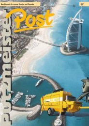
In brief<br />
In brief<br />
Caution:<br />
Snappy ad!<br />
"Since I have the eye-catching writing<br />
on my M 52, my customers are ordering<br />
nothing but the "Big Dog", states<br />
Robert Heider, Managing Director of<br />
the concrete pump services Heider<br />
from Wolfegg im Allgäu. As he was<br />
in the area, he made a pit stop at the<br />
<strong>Putzmeister</strong> plant in Aichtal.<br />
<strong>42</strong><br />
uRobert Heider (right) and<br />
Jörg Hermann, Manager of<br />
the Workshop Service Centre<br />
in Aichtal (left)<br />
61<br />
In the <strong>Putzmeister</strong> Post 79 we reported<br />
on the spectacular concreting at the<br />
double arch of the Hoover Dam bypass<br />
bridge which was effected in October<br />
2009.<br />
A year and a half later in April 2010 the<br />
bridge was once again the scene of an<br />
exciting event: A M 52 was "flown" to<br />
its airy workplace by cable crane.<br />
A total of eleven fields, each 27 x 37 m,<br />
of the future road had to be concreted.<br />
Pump service providers Quinn from<br />
Las Vegas, who were assigned the entire<br />
project with regard to equipment<br />
and machine operators, were in demand<br />
with their M 52 as a semi-trailer.<br />
<strong>The</strong> large range was decisive in the<br />
choice, but also its semi-trailer configuration.<br />
<strong>The</strong> truck-mounted concrete<br />
pump was able to be "alleviated" with<br />
its tractive unit and positioned on-site<br />
on a special counterweight using a<br />
crane.<br />
<strong>The</strong> M 52 was positioned at the peak<br />
of the arch. To distribute the load<br />
symmetrically and balance the bridge<br />
arch, it concreted one area on one side<br />
and then one area on the other side.<br />
Always rotating until all eleven areas<br />
were complete.<br />
<strong>The</strong> rotation of the pumps was necessary<br />
as the supply line from the stationary<br />
concrete pumps, which fed the<br />
M 52, would otherwise have been in<br />
the way.<br />
<strong>The</strong> Hoover Dam bypass bridge has<br />
been in operation since October 2010<br />
and is called the "Mike O’Callaghan<br />
– Pat Tillman Memorial Bridge". <strong>The</strong><br />
construction of the almost 610 m long<br />
bridge took roughly five and a half<br />
years.<br />
62<br />
M 52 approaching<br />
the Hoover Dam<br />
bypass bridge<br />
63<br />
28 PM 4377 GB PM 4377 GB 29
In brief<br />
In brief<br />
In the Saudi Arabian capital Riad<br />
construction has begun on the "King<br />
Abdullah Financial District" (KAFD).<br />
<strong>The</strong> ambitious project with a volume<br />
of 10 billion US$ will comprise more<br />
than 40 skyscrapers on an area of 1.6<br />
million m 2 and should be completed<br />
within a construction period of just<br />
three and a half years.<br />
"Saudi Arabia is to become the financial<br />
centre of the Middle East." This proposal<br />
and the large personal interest<br />
of the head of state and government<br />
King Abdullah bin Abdulaziz Al Saud<br />
are helping the project to advance<br />
quickly and consistently. Construction<br />
of the first 10 of 40 lots began at the<br />
end of 2009; after only 30 months they<br />
should already be complete. <strong>The</strong> same<br />
short construction period is estimated<br />
for the other sub-projects. 70 % of the<br />
building should be complete by the<br />
middle of 2012.<br />
<strong>The</strong> concept of the KAFD not only envisages<br />
exclusive offices for financial<br />
companies. Approximately one quarter<br />
of the 5 million m 2 building area is<br />
intended for residential apartments.<br />
Six hotels are planned, as well as<br />
numerous shops and leisure facilities.<br />
What is important for the builders is to<br />
create a pulsating city in the day and<br />
at night and to create a harmonious<br />
connection between work, living and<br />
leisure.<br />
According to the principle of a "Wadi" – a<br />
Wadi describes a dry riverbed which contains<br />
water only during times of heavy<br />
rainfall – in the entire complex there<br />
are shaded footpaths with water features<br />
and plants, as well as lots of airconditioned<br />
"sky walks" between the<br />
towers and a single-track rail around the<br />
district. Each skyscraper has four under-<br />
Large project in Saudi Arabia:<br />
King Abdullah Financial District<br />
ground car parks. Together with the<br />
complex traffic routing, the KAFD remains<br />
practically car-free.<br />
<strong>The</strong> quantity of concrete required for<br />
the construction of 1.6 million m 3 is gigantic<br />
– 2000 m 3 should be used every<br />
day.<br />
<strong>Putzmeister</strong> is helping with this project<br />
not only with reliable pumps and<br />
placing booms, but is also on hand to<br />
provide project advice.<br />
64<br />
65<br />
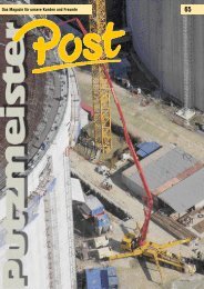
Telebelt reduces the<br />
costs of placing mass<br />
concrete in Chinese<br />
shipyard<br />
Titan Quanzhou Shipyard Co. in Hui’an,<br />
Quanzhou in the Chinese province of<br />
Fujian is part of the Titan Petrochemicals<br />
Group Ltd. <strong>The</strong> shipyard consists of<br />
a cofferdam, an outer quay and four<br />
dry docks. Dock 1 is the main shipyard<br />
and consists of the dock entrance, wall,<br />
foundation, passage, drainage system<br />
and pump house.<br />
<strong>The</strong> project started in 2006 and the<br />
concreting work began in March 2010.<br />
<strong>The</strong> first and second docks are due to<br />
be completed by the end of May 2011.<br />
For the concrete placement, the main<br />
items of equipment being used are a<br />
<strong>Putzmeister</strong> Telebelt TB 110 G, three<br />
12 m 3 truck mixers and one 3 m 3 mixing<br />
facility located 500 m from the<br />
construction site.<br />
Large quantities of concrete used for<br />
the foundation of the shipyard<br />
entrance and the pump house<br />
<strong>The</strong> foundation of the pump house, for<br />
example, is 54 x 41 m and 2 m thick<br />
with a total of 4,800 m 3 of concrete.<br />
To construct this foundation, concrete<br />
had to be conveyed continuously. No<br />
problem: Telebelt operated without interruption<br />
for 67 hours and completed<br />
the job perfectly. <strong>The</strong> fuel consumption<br />
was measured during the placement.<br />
<strong>The</strong> result: 1,000 litres of diesel for 5,300<br />
cubic metres of placed concrete.<br />
Telebelt concretes the dock wall<br />
<strong>The</strong> concrete for the dock wall was<br />
poured in three layers and the maximum<br />
height of the wall was 12.6 m. <strong>The</strong> Telebelt<br />
was set up directly at the wall.<br />
And, with the conveyor belt's maximum<br />
working height of 18 m, the Telebelt<br />
had plenty in reserve for the operation.<br />
When concreting the walls, the quiet,<br />
no-vibration conveyor belt was more advantageous<br />
and reliable.<br />
<strong>The</strong> perfect conveyor belt for the base<br />
plate of the dock<br />
<strong>The</strong> foundation plate was 60 cm thick<br />
and the entire surface was divided into<br />
several segments, with each segment requiring<br />
225 m 3 of concrete. <strong>The</strong> big advantage<br />
of the Telebelt in this case was<br />
its ability to convey the concrete horizontally.<br />
Ideal and time-saving for this<br />
type of concreting.<br />
66<br />
ÄÄTitan Quanzhou Shipyard<br />
<strong>The</strong> location of the Titan Quanzhou<br />
shipyard on important merchant<br />
shipping routes and its relatively<br />
close proximity to important ports,<br />
such as Shanghai (502 nautical<br />
miles) or Hong Kong (386 nautical<br />
miles), make it an ideal point of approach<br />
along this coast.<br />
<strong>The</strong> shipyard is expected to be operational<br />
in 2012, when it will become<br />
one of the largest in the world, with<br />
huge capacities for repairing and reconstructing<br />
supertankers (VLCC),<br />
large bulk carriers, RORO ships and<br />
even the largest container ships that<br />
are currently sailing the world.<br />
<strong>The</strong> shipyard comprises 110 hectares<br />
of land with a coastline that is 3.6<br />
km long.<br />
<strong>The</strong> dimensions of the docks<br />
Dock 1<br />
Dock 2<br />
Dock 3<br />
and 4<br />
380 x 80 x 14.4 m<br />
<strong>42</strong>0 x 68 14.65 m<br />
each is 280 x 46 x 12.8 m<br />
Save money and time with the reliable<br />
Telebelt<br />
Telebelt can convey concrete with a<br />
low slump and a relatively large particle<br />
distribution. Concrete mixes of<br />
this kind are mainly used as mass concrete<br />
because, on the one hand, they<br />
produce less hydration heat and, on<br />
the other, they are significantly less<br />
expensive than pumpable concrete. As<br />
a result, they considerably reduce the<br />
costs for a project such as this one.<br />
In comparison to other methods of<br />
concrete placement, the TB 110 G has<br />
saved a lot of time thanks to its large<br />
output and high level of mobility.<br />
Since the beginning of the concreting<br />
work, the Telebelt was extremely reliable<br />
to use. Except for scheduled<br />
service work, there were no downtimes<br />
during this time.<br />
By September 2010, the TB 110 G had<br />
already placed 45,000 m 3 of concrete<br />
and, by April 2011, it had pumped as<br />
much as 130,000 m 3 on this shipyard<br />
construction site.<br />
[<strong>Putzmeister</strong> Machinery Shanghai Co. Ltd.]<br />
30 PM 4377 GB PM 4377 GB 31
<strong>Putzmeister</strong> Services information:<br />
Longer service life<br />
for your delivery line<br />
Sponge ball<br />
for Ø 120, 125, 140<br />
• Every ball now packed<br />
with dirt-resistance<br />
• Now even more tear-resistant<br />
• Optimal resetting properties<br />
5.10 €<br />
part-no. 018841002<br />
67<br />
Clean<br />
& Tight<br />
68<br />
<strong>The</strong> prices quoted are net prices EXW Aichtal, as at 05/2011.<br />
Prices become invalid upon the publication of <strong>new</strong> price lists for spare parts.<br />
Set of seals * SK 125 5,5Z<br />
• Increases the service life<br />
of the seal in the swivel<br />
• Use in typical SK 5.5"<br />
couplings possible<br />
4.10 €<br />
part-no. 48<strong>42</strong>16<br />
More informationen is available from:<br />
Tel. +49 (0) 7127 599 297 · spareparts@putzmeister.de<br />
* Seal and storage (blue)<br />
PM 4377 GB