Voyager AOM681 Manual (PDF) - Ward Electronics
Voyager AOM681 Manual (PDF) - Ward Electronics
Voyager AOM681 Manual (PDF) - Ward Electronics

Create successful ePaper yourself
Turn your PDF publications into a flip-book with our unique Google optimized e-Paper software.
R<br />
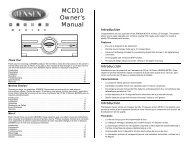
<strong>AOM681</strong><br />
6.8” FLAT PANEL COLOR OBSERVATION<br />
MONITOR OWNER’S MANUAL<br />
<strong>AOM681</strong> Features:<br />
? 6.8” High Performance Color LCD<br />
? Water Resistant Design<br />
? Built-in Audio Speaker with Volume Control<br />
and 12V Trigger<br />
? 2 Camera (A/V) Input with A/B Select Control<br />
? Backlit Controls and Day/Night Picture Modes<br />
for Nighttime Use<br />
? Auto/<strong>Manual</strong> Power On<br />
? Sun Visor Included<br />
Visit us at http://www.asaelectronics.com<br />
UDIOVOX<br />
PECIALIZED<br />
1<br />
PPLICATIONS, L.L.C.
Important! – Please Read This <strong>Manual</strong> Before Installing!<br />
Congratulations on your purchase of a <strong>Voyager</strong> <strong>AOM681</strong> LCD Observation Monitor.<br />
With proper installation and use, your <strong>AOM681</strong> is designed to provide you with years of<br />
trouble-free operation. This manual contains important information required to properly<br />
install and operate the unit. Please read this manual thoroughly before beginning.<br />
All <strong>Voyager</strong> Observation products are strictly intended to be installed as a supplement aid<br />
to standard rear-view mirror systems that may already exist in your vehicle. <strong>Voyager</strong><br />
observation products are not intended for use as substitutes for rear-view mirror devices,<br />
or for any other standard motor vehicle equipment required to be installed on vehicles by<br />
law.<br />
While <strong>Voyager</strong> observation products contribute to improving the vehicle operator’s field<br />
of view, these products are no substitute for proper defensive driving techniques and<br />
observance of traffic laws and motor vehicle safety regulations.<br />
Warnings!<br />
Installation Location<br />
It is unlawful in most jurisdictions for a person to drive a motor vehicle equipped with a<br />
television viewer or screen located at any point forward of the back of the driver’s seat or<br />
in any location that is visible, directly or indirectly, to the driver while operating the<br />
vehicle. The <strong>AOM681</strong> product is designed to be used primarily as a rear observation<br />
device in conjunction with closed circuit cameras. In any installations where the<br />
<strong>AOM681</strong> is used to display television broadcasts or recorded video playback, installation<br />
location must adhere to local laws and regulations.<br />
Tampering<br />
To prevent electrical shock, DO NOT OPEN THE MONITOR CASE. There are<br />
potentially harmful voltages inside the monitor. There are no user serviceable parts<br />
inside. If evidence of tampering is detected, the warranty will be considered void.<br />
Moisture<br />
Your <strong>Voyager</strong> <strong>AOM681</strong> was designed to be water-resistant. While it will withstand short<br />
periods of exposure to moisture, this product does contain sensitive electronic<br />
components and exposure to moisture should be limited by the user / installer. This<br />
product is not designed for applications where constant exposure to moisture or<br />
immersion can be encountered. This unit should NEVER be cleaned with a power<br />
washer or used where direct power washer spray may be encountered.<br />
2
Audiovox Specialized Aplications, LLC (the company) warrants to the original retail purchaser of<br />
this product that should this product or any part thereof, under normal use and conditions, be<br />
proven defective in material or workmanship within 90 days from the date of purchase, such<br />
defect(s) will be repaired or replaced (at the company's option) without charge for parts and labor<br />
repair. After the initial 90 day period and for a period of 12 months from the date of original<br />
purchase, the company will supply at no charge a replacement for any defective part(s) but will<br />
charge for the labor to repair the product.<br />
To obtain repair or replacement within the terms of this Warranty, ASA must be called and a return<br />
authorization must be given to reference the product when returned. The product is to be delivered<br />
with proof of waranty coverage (e.g. dated bill of sale), specification of the defect(s), transportation<br />
prepaid, and Return Authorization Number clearly written on the outside of the package. The<br />
product must be returned to ASA for repair unless specified otherwise by ASA.<br />
This warranty does not cover the elimination of externally generated static or noise, to the correction<br />
of antenna problems, to costs incurred for removal or reinstallation of the product, or damage to any<br />
tapes, speakers, accessories, or electrical systems.<br />
This warranty does not apply to any product or part thereof which in the opinion of the company has<br />
been damaged through alteration, improper installation, mishandling, misuse, neglect or accident.<br />
THE EXTENT OF THE COMPANY'S LIABILITY UNDER THIS WARRANTY IS LIMITED TO THE<br />
REPAIR OR REPLACEMENT PROVIDED ABOVE AND, IN NO EVENT SHALL THE COMPANY'S<br />
LIABILITY EXCEED THE PURCHASE PRICE PAID BY THE PURCHASER FOR THE PRODUCT.<br />
This warranty is in lieu of all other express warranties or liabilities, ANY IMPLIED WARRANTIES,<br />
INCLUDING ANY IMPLIED WARRANTY OF MERCHANTABILITY, SHALL BE LIMITED TO THE<br />
DURATION OF THIS WARRANTY. ANY ACTION OR ANY BREACH OF ANY WARRANTY<br />
HEREUNDER INCLUDING ANY IMPLIED WARRANTY OF MERCHANTABILITY MUST BE<br />
BROUGHT WITHIN A PERIOD OF 30 DAYS FROM THE DATE OF PURCHASE. IN NO CASE<br />
SHALL THE COMPANY BE LIABLE FOR ANY CONSEQUENTIAL OR INCIDENTAL DAMAGES<br />
OR BREACH OF THIS OR ANY OTHER WARRANTY, EXPRESS OR IMPLIED, WHATSOEVER.<br />
NO person or representative is authorized to assume for the Company any other than expressed<br />
herein connection of the sale of this product. Some states do not allow limitations on how long an<br />
implied warranty lasts or the exclusion of incidental or consequential damages so the above<br />
limitations or exclusions may not apply to you. This gives you specific legal rights and you may also<br />
have other rights which vary from state to state.<br />
Audiovox Specialized Applications, LLC<br />
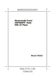
PACKING CONTENTS:<br />
90 DAY/ 12 MONTH LIMITED WARRANTY<br />
WARRANTY CARD<br />
QTY. 1<br />
LCD MONITOR<br />
QTY. 1<br />
SUN SHIELD<br />
QTY. 1<br />
4” X 2” VELCRO<br />
QTY. 1<br />
5’ INTERMEDIATE HARNESS<br />
QTY. 1<br />
TRIGGER (+12V)<br />
STANDBY<br />
#8 X ¾” SELF DRILL BLACK SCREWS (HARDWARE<br />
BAG)<br />
QTY.4<br />
ACC(+12V)<br />
TRIGGER (+12V)<br />
AUDIO<br />
GND<br />
#10 X 5/16” PHP THREAD FORMING BLACK<br />
SCREW (HARDWARE BAG) QTY. 4<br />
POWER HARNESS QTY. 1<br />
LCD<br />
POWER PANEL A/V 1 A/V 1<br />
5<br />
2<br />
1<br />
SPLIT GROMMET<br />
1” O.D. 3/16 I.D.<br />
QTY. 1<br />
STOP<br />
DISTANCE MARKER<br />
STICKER<br />
QTY.1<br />
A/V INPUT JUNCTION BOX<br />
QTY.1<br />
4” BLACK WIRE TIE<br />
QTY. 4<br />
3
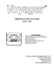
CONTROLS AND OPERATION<br />
1<br />
2<br />
3<br />
4<br />
5<br />
5<br />
1. Power/Stand-By Button<br />
The <strong>AOM681</strong> has two possible operation modes for turning the unit on/off. In manual<br />
mode, the power button is used to turn the unit on/off. In stand-by mode, the unit<br />
automatically turns on only when 12V is applied to the stand-by trigger wire.<br />
For MANUAL operation, the <strong>AOM681</strong> should be wired as follows:<br />
The ACC (+12V) lead (red) should be wired to the ACC feed of the vehicle (switched +12V).<br />
*Please note that if the unit is in “Stand-by On” mode, the Power Button will appear to<br />
have no effect (it will switch from “on” to “on” in this case).<br />
For STAND-BY operation, the <strong>AOM681</strong> should be wired as follows:<br />
The ACC (+12V) lead (red) should be wired to the ACC feed of the vehicle (switched<br />
+12V). The Stand-by Trigger (+12V) should be wired to the reverse feed of the vehicle<br />
(+12V when the vehicle is in reverse). The unit will automatically turn on whenever the<br />
standby trigger is +12V.<br />
The power button features dual-illumination (bright and dim). In installations where the<br />
unit is not wired for Stand-by operation and power is applied to the unit, the Power<br />
Button will dimly glow when the unit is off, allowing the user to easily find the control in<br />
low light. Illumination switches to full intensity when the unit is turned on.<br />
2. A/B Input Select Button<br />
This control toggles the active display image back and forth between AV1 and AV2<br />
inputs.<br />
4
3. Day/Night Mode Button This control toggles the unit between “Day” and “Night”<br />
LCD illumination modes. In the “Day” mode, the LCD backlight intensity is at<br />
maximum. In “Night” mode, the LCD backlight is dimmed to a preset level that is more<br />
suitable for low light operation.<br />
4. Picture Adjustment Menu Button<br />
This control accesses an On-Screen-Display (OSD) menu for four LCD picture<br />
adjustments (Brightness, Contrast, Color, and Tint). The first depress of the button<br />
accesses the “Brightness” adjustment. The Volume +/- controls adjust the level, which is<br />
indicated by the bar graph at the bottom of the screen. Each consecutive depress of the<br />
Picture button accesses the adjustment screen for each picture adjustment. If no buttons<br />
are pressed within 6 seconds or controls other than the Picture and Volume buttons are<br />
pressed, the unit will exit the Picture Adjustment mode.<br />
5. Volume +/- Buttons<br />
This 2-button set of controls adjusts the output volume of the built-in audio speaker when<br />
the audio function is enabled *(see typical system connection diagram). The “+” button<br />
increases output volume. The “-“ button decreases output volume. Volume level is<br />
indicated by the OSD bar graph at the bottom of the screen.<br />
These buttons also serve as adjustment controls while in the Picture Adjustment Menu<br />
mode (see above section for details).<br />
*Note: The <strong>AOM681</strong> requires +12V to be applied to the “Audio Enable” trigger input in<br />
order to activate the built-in speaker. If no audio output is heard from the speaker<br />
regardless of the volume level adjustment, check this connection.<br />
5
INSTALLATION INSTRUCTIONS<br />
BEFORE YOU BEGIN INSTALLATION:<br />
Before drilling, be sure that no cable or wiring is on the other side. Clamp all wires<br />
securely to reduce the possibility of them being damaged during installation and use.<br />
Keep all cables away from hot or moving parts, and electrically noisy components.<br />
Wiring Definitions:<br />
? Power connection: Pin 1 ACC +12V (Red)<br />
Pin 2 Standby Trigger (Blue wire)<br />
Pin 3 Ground (Black wire)<br />
Pin 4 Audio Trigger (Blue w/white stripe wire)<br />
? Camera A input: Connection for camera or camera extension cable<br />
? Camera B input: Connection for camera or camera extension cable<br />
? LCD panel: 9-pin DIN cable connection: junction box to monitor.<br />
Procedure:<br />
1. Choose the monitor, junction box, and camera mounting locations.<br />
2. Install all required cables in vehicle. A ¾” (19mm) hole should be drilled for passing<br />
cables through vehicle walls, barriers, etc. After the intermediate cable is passed<br />
through the hole, install the split grommet (included). If additional cable protection is<br />
required install convoluted tubing over the cable.<br />
3. After cable/wiring has been routed and components are in place, temporarily make all<br />
system connections and perform a system function check. If system does not operate<br />
properly, see the troubleshooting section of this manual.<br />
4. If using an optional PanaVise ? stalk mount (available separately), use the mounting<br />
template provided on page 10. Install the PanaVise ? mount to the LCD monitor<br />
using the #10 self-drilling screws (included).<br />
**Important: Do not use screws other than those provided with the <strong>AOM681</strong>.<br />
Void of warranty and serious product damage will occur.<br />
5. Use the template provided on page 10 for proper placement of the junction box<br />
mounting holes. Use the #8 self-drilling screws (included) to secure the junction box<br />
in the desired location. The junction box can also be mounted using the 2”x 4” velcro<br />
strip (included).<br />
6
6. There are 2 options for connecting the LCD monitor to the junction box. If the<br />
application is such that the monitor is in close proximity to the junction box, the<br />
<strong>AOM681</strong> monitor can be connected directly to the junction box. If the junction box<br />
is mounted further from the monitor, use the 5’ intermediate cable included with the<br />
<strong>AOM681</strong> to connect the monitor to the junction box. If more cable length is needed,<br />
additional 5’ lengths of the intermediate cable can be purchased. (See the accessory<br />
list at the back of this manual for part number details.)<br />
7. Connect the 4-pin power harness to vehicle. (See system connection illustration page<br />
8)<br />
8. Plug camera extension cable (available separately P/N CEC25) into AV1 or AV2<br />
input connector on the junction box. Plug observation camera into camera extension<br />
cable.<br />
9. Make sure all cables are routed away from hot or moving parts, and away from sharp<br />
edges. Secure cables with wire ties.<br />
10. For rear observation applications, range marker stickers have been included with this<br />
product. These markers are designed to adhere to your LCD monitor and provide a<br />
reference for gauging distance. See page 9 for illustration showing proper use and<br />
installation of the range markers<br />
7
A<br />
B<br />
GND<br />
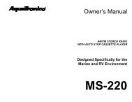
TYPICAL SYSTEM CONNECTION<br />
ACCESSORY ITEM<br />
MULTI-AXIS BASES (2 AVAILABLE)<br />
72704 - 4”2-AXIS BASE MOUNT<br />
72706 - 6”3-AXIS BASE MOUNT<br />
ACCESSORY ITEMS<br />
CEC5 - 5 FT. CAMERA CABLE<br />
CEC15 - 15 FT. CAMERA CABLE<br />
CEC18 - 18 FT. CAMERA CABLE<br />
CEC25 - 25 FT. CAMERA CABLE<br />
CEC50 - 50 FT. CAMERA CABLE<br />
CEC75 - 75 FT. CAMERA CABLE<br />
ACCESSORY ITEM (2 AVAILABLE)<br />
AOC100B - COLOR CAMERA SWITCHABLE<br />
STD/MIRROR IMAGE<br />
VCC130 - COLOR CAMERA WITH LOW-LIGHT<br />
ENHANCEMENT LED’s<br />
<strong>AOM681</strong> LCD MONITOR<br />
(BLUE) +12V STANDBY TRIGGER<br />
(RED) +12V SWITCHED<br />
L CD<br />
#8 X 3/4”SELF<br />
DRILLING SCREWS<br />
T RIGG ER (+ 12V)<br />
AUDIO<br />
ACC (+1 2V)<br />
TR IGGE R (+1 2V)<br />
STA NDBY<br />
P OW ER PANE L A/V 1 A/V 2<br />
(BLUE/WHITE) AUDIO TRIGGER<br />
(BLACK) CHASSIS GROUND<br />
JUNCTION BOX<br />
8510681 5’INTERMEDIATE CABLE<br />
+<br />
–<br />
#10 X 5/16”<br />
TYPE B<br />
SCREWS<br />
8
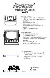
REAR OBSERVATION INSTALLATION<br />
DISTANCE MARKER USE/INSTALLATION<br />
-PLACE INDICATOR MARKERS (CONE, BOX ANY<br />
REFERENCE OBJECT HANDY) BEHIND VEHICLE<br />
AS IN FIGURE A.<br />
-PLACE RANGE MARKER DECALS ON SCREEN OF<br />
MONITOR OVER IMAGE OF INDICATOR<br />
MARKERS ON GROUND BEHIND VEHICLE, AS<br />
VIEWED ON THE MONITOR SCREEN.<br />
-THIS GIVES YOU A VISUAL REFERENCE OF<br />
ACTUAL DISTANCE BEHIND VEHICLE, AS<br />
OBJECTS ARE VIEWED.<br />
INDICATOR<br />
MARKERS<br />
1 FT<br />
2 FT<br />
5 FT<br />
WIDTH OF VEHICLE<br />
FIGURE A<br />
5<br />
2<br />
1<br />
STOP<br />
9<br />
FIGURE B
JUNCTION BOX MOUNTING TEMPLATE<br />
PANAVISE ? MOUNT TEMPLATE<br />
(OPTIONAL ACCESSORY – SEE PAGE 8)<br />
SIDE<br />
10
TROUBLESHOOTING<br />
SYMPTOM CAUSE SOLUTION<br />
No power<br />
No +12V accessory, No<br />
ground, mis-wired/reversed<br />
Replace circuit fuse, monitor has protection<br />
device built-in/reset, check ground connection,<br />
verify power is being supplied<br />
Video/No audio<br />
Monitor does not<br />
activate in reverse<br />
Blue/white audio trigger wire<br />
not powered, Volume adjust<br />
down<br />
Blue standby wire not<br />
powered<br />
Connect to +12V ACC or reverse light circuit,<br />
turn volume adjustment up<br />
Connect to reverse circuit +12V<br />
Negative/dark<br />
video image<br />
Low voltage, Brightness<br />
adjustment down<br />
Check voltage power and ground connections,<br />
turn brightness adjustment up<br />
No video/no audio Camera connection Check camera input selection, connection to<br />
camera and junction box, correct camera<br />
connection/plugged incorrectly<br />
Vehicle battery<br />
drained<br />
+12V ACC (red wire)<br />
connected to vehicle battery<br />
Provide +12V ACC (red wire) power from<br />
switched circuit<br />
ACCESSORY LIST<br />
AOC100B – COLOR CAMERA-SWITCHABLE STD/MIRROR IMAGE<br />
VCC130 - COLOR CAMERA W/LOW LIGHT ENHANCEMENT LED’s-MIRROR<br />
IMAGE ONLY<br />
CEC2 – 2 FOOT CAMERA EXTENSION CABLE<br />
CEC15 – 15 FOOT CAMERA EXTENSION CABLE<br />
CEC18 – 18 FOOT CAMERA EXTENSION CABLE<br />
CEC25 – 25 FOOT CAMERA EXTENSION CABLE<br />
CEC50 – 50 FOOT CAMERA EXTENSION CABLE<br />
CEC75 – 75 FOOT CAMERA EXTENSION CABLE<br />
8510681 – 5 FOOT INTERMEDIATE HARNESS<br />
CSW4000 – MANUAL 4 CAMERA SWITCHER<br />
CSW450A – AUTOMATIC 4 CAMERA SWITCHER<br />
FDK681N - FLIP DOWN KIT, <strong>AOM681</strong> NEUTRAL<br />
FKD681G – FLIP DOWN KIT, <strong>AOM681</strong> GRAY<br />
FDK681PL – FLIP DOWN KIT, <strong>AOM681</strong> PEARL<br />
72704 – CELLULAR MOUNT 4” WITH THUMBSCREW<br />
72706 – CELLULAR MOUNT 6” WITH THUMBSCREW<br />
11
PRODUCT SPECIFICATIONS<br />
LCD panel specifications:<br />
Size/Type 6.8” (diagonal) /TFT LCD<br />
Brightness 250 nit (min)<br />
300 nit (typ.)<br />
Contrast Ratio 60 (min)<br />
150 (typ.)<br />
View Angles Top (12 o’clock): 25?(min)<br />
(@ CR?10) Bottom (6 o’clock): 40?(min)<br />
Horizontal: ? 55? (min)<br />
Response Time Rise: 25ms (typ.) ; 50ms (max)<br />
Fall: 30ms (typ.) ; 60ms (max)<br />
Back light Type CCFL<br />
Back light Life 30k hrs (min) ; 40k hrs (typ.)<br />
Operation Temperature Range: -20?C to 65?C<br />
Storage Temperature Range: -40?C to 80?C<br />
Max Humidity:<br />
100? RH<br />
Max Vibration Force: 2.5G<br />
Max Shock Force:<br />
100G<br />
Operating Voltage Range: 10VDC to 16VDC<br />
Current Draw (typical):<br />
50mA (Idle); 1.15A (typ) ; 1.25A (max)<br />
Signal System:<br />
NTSC<br />
Video:<br />
? Aspect Ratio: 4:3<br />
? Input format: Composite NTSC<br />
? Input level: 1Vp-p into 75?<br />
Audio<br />
? Input level: -10dBV nominal (317mV)<br />
Product Weight:<br />
2.8lbs (approximate)<br />
Product Overall Dimensions: 7 ¾” (197mm)W x 5 ¼” (134mm)H x 1 3/16” (29.5mm)D<br />
Visit us at http://www.asaelectronics.com<br />
12