Defender Workshop Manual (1993). - Internet-Tools.co.uk
Defender Workshop Manual (1993). - Internet-Tools.co.uk
Defender Workshop Manual (1993). - Internet-Tools.co.uk

Create successful ePaper yourself
Turn your PDF publications into a flip-book with our unique Google optimized e-Paper software.
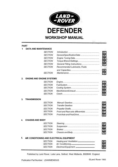
DEFENDER<br />
WORKSHOP MANUAL<br />
PART<br />
1 DATA AND MAINTENANCE<br />
SECTION Introduction ....................................................<br />
SECTION General Specification Data ................................<br />
SECTION Engine Tuning Data.............................................<br />
SECTION Torque Wrench Settings........................................<br />
SECTION General Fitting Instructions................................<br />
SECTION Re<strong>co</strong>mmended Lubricants, Fluids<br />
SECTION<br />
2. ENGINE AND ENGINE SYSTEMS<br />
and Capacities...................................................<br />
Maintenance.......................................................<br />
SECTION Engine .............................................................<br />
SECTION Fuel System .....................................................<br />
SECTION Cooling System..............................................<br />
SECTION Manifold and Exhaust ........................................<br />
SECTION Clutch...............................................................<br />
3. TRANSMISSION<br />
SECTION<br />
SECTION<br />
<strong>Manual</strong> Gearbox...............................................<br />
Transfer Gearbox<br />
SECTION Propeller Shafts ...............................................<br />
SECTION Front and Rear axle differentials ......................<br />
SECTION Front Axle and Final Drive...................................<br />
4. CHASSIS AND BODY<br />
SECTION Steering ..........................................................<br />
SECTION Suspension ....................................................<br />
SECTION Brakes ...........................................................<br />
SECTION Chassis and Body ...........................................<br />
5. AIR CONDITIONING AND ELECTRICAL EQUIPMENT<br />
SECTION Heating and Ventilation ......................................<br />
SECTION Air Conditioning ..................................................<br />
SECTION Electrical Equipment ..........................................<br />
Published by Land Rover, Lode Lane, Solihull, West Midlands, B92 8NW. England.<br />
Publication Part Number: LDAWMEN93US<br />
©Land Rover <strong>1993</strong>
Section<br />
Number<br />
PART ONE CONTENTS<br />
Page<br />
01<br />
INTRODUCTlON<br />
• Warnings and cautions 1<br />
• References 1<br />
• Dimensions 1<br />
• Repairs and replacements 1<br />
• Fuel handling precautions 1<br />
• Re<strong>co</strong>mmended sealants 2<br />
• Poisonous and dangerous substances 3<br />
• Disposing of used oil and fluids 3<br />
• Accessories and <strong>co</strong>nversions 4<br />
• Specification 4<br />
• Special service tools 5<br />
• Abbreviations and symbols 6<br />
• Location of vehicle identification and unit numbers 7<br />
04<br />
GENERAL SPECIFICATlON DATA<br />
• V8 engine data 1<br />
• Transmission 3<br />
• Propeller shafts 3<br />
• Suspension 3<br />
• Brakes 4<br />
• Steering 4<br />
• Electrical equipment 5<br />
• Replacement bulbs and units 6<br />
• Vehicle dimensions 7<br />
• Vehicle weights and payload 7<br />
• Wheels and tires 8<br />
• Tire Pressures 8<br />
ENGINE TUNING DATA<br />
• V8 engine tuning data 1<br />
06<br />
TORQUE WRENCH SETTINGS<br />
• Engine 1<br />
• Fuel lines 1<br />
• Clutch 1<br />
• Gearbox 2<br />
• Transfer box 3<br />
• Front axle 3<br />
• Rear axle and final drive 4<br />
• Propeller shafts 4<br />
• Rear suspension 4<br />
• Steering and front suspension 4<br />
• Power assisted steering 5<br />
• Brakes 5<br />
• Electrical 5<br />
• Air Conditioning 5<br />
REISSUED: FEB <strong>1993</strong>
PART ONE CONTENTS<br />
Page<br />
07<br />
GENERAL FITTING INSTRUCTIONS<br />
• Precautions against damage 1<br />
• Safety precautions 1<br />
• Preparation 1<br />
• Dismantling 1<br />
• Inspection • general 2<br />
• Ball and roller bearings 2<br />
• Oil seals 2<br />
• Joints and joint faces 3<br />
• Flexible hydraulic pipes, hoses 3<br />
• Metric bolt identification 4<br />
• Metric nut identification 4<br />
• Hydraulic fittings 4<br />
• Keys and keyways 5<br />
• Tab washers 5<br />
5<br />
6<br />
6<br />
6<br />
6<br />
09<br />
RECOMMENDED LUBRICANTS, FLUIDS AND CAPACITIES<br />
• Re<strong>co</strong>mmended lubricants 1<br />
• Anti-freeze 2<br />
• Capacities 3<br />
10<br />
MAINTENANCE<br />
• <strong>Workshop</strong> maintenance schedules 1<br />
• Lubrication 9<br />
• General maintenance and adjustment 12<br />
REISSUED: FEB <strong>1993</strong>
Section<br />
Number<br />
PART TWO CONTENTS<br />
Page<br />
ENGINE<br />
• Description 1<br />
• Engine fault diagnosis 7<br />
• Engine removal 11<br />
• Engine dismantle and overhaul 13<br />
• Assembling engine 31<br />
• Service tools 49<br />
EMISSION CONTROL<br />
• Emission <strong>co</strong>ntrol 1<br />
• Crankcase ventilation system 1<br />
• Evaporative emission <strong>co</strong>ntrol 2<br />
• Fuel tank evaporative <strong>co</strong>ntrol<br />
• Evaporative purge system operation<br />
• Fuel tank evaporative <strong>co</strong>ntrol system operation<br />
• Fuel expansion tank - remove and refit<br />
• Heated oxygen sensor - remove and refit<br />
•<br />
Char<strong>co</strong>al canister - remove and refit<br />
• Char<strong>co</strong>al canister - purge valve - remove and refit<br />
• Positive crankcase ventilation<br />
• Air intake filter - remove and refit 6<br />
• Breather filter - remove and refit 6<br />
• Emission label 7<br />
2<br />
2<br />
3<br />
4<br />
4<br />
5<br />
5<br />
FUEL SYSTEM<br />
- Diagnostic equipment 1<br />
• Hot wire multiport fuel injection 2<br />
• Engine tuning 4<br />
• Multi meter checks 4<br />
• Multi port fuel injection • circuit diagram 5<br />
• Base idle speed setting 6<br />
• Fuel pressure check 7<br />
• Injector tests 7<br />
• Removing air cleaner 8<br />
• Removing mass air flow sensor<br />
• Removing throttle position sensor<br />
• Removing idle air <strong>co</strong>ntrol valve<br />
• Removing vehicle speed sensor<br />
• Removing fuel injection • relay modules<br />
• Removing inertia fuel shut-off switch<br />
• Removing engine fuel temperature sensor<br />
• Removing engine <strong>co</strong>olant temperature sensor<br />
• Depressurising fuel system<br />
8<br />
9<br />
9<br />
10<br />
10<br />
11<br />
11<br />
11<br />
12<br />
• Removing fuel pressure regulator<br />
12<br />
• Removing fuel rail - injectors r/h and l/h 13<br />
• Removing plenum chamber 14<br />
• Removing ram housing 19<br />
• Removing intake manifold 19<br />
• Removing fuel filter 20<br />
• Removing fuel tank and fuel pump<br />
21<br />
• Removing accelerator cable 23<br />
• Removing accelerator pedal 24
Section<br />
Number<br />
PART TWO CONTENTS<br />
Page<br />
COOLING SYSTEM<br />
• Engine protection 1<br />
• Drain and refill <strong>co</strong>oling system<br />
• Removing water pump<br />
1<br />
2<br />
• Removing thermostat 2<br />
• Removing radiator 4<br />
• Cooling system fault diagnosis<br />
5<br />
MANIFOLDS AND EXHAUST<br />
• Exhaust system <strong>co</strong>mplete 1<br />
• Exhaust system - remove and refit 2<br />
• Exhaust manifold - remove and refit 3<br />
CLUTCH<br />
• Clutch assembly renewal 1<br />
• Clutch fault diagnosis 2<br />
• Clutch release bearing assembly - overhaul 3<br />
• Master cylinder - overhaul 3<br />
• Slave cylinder • overhaul 5<br />
• Clutch pedal adjustment 6<br />
• Bleed clutch hydraulic system 6<br />
• Renew clutch slave cylinder 7<br />
• Renew clutch master cylinder 8
Section<br />
Number<br />
PART THREE CONTENTS<br />
Page<br />
- Remove and refit<br />
- Overhaul 4<br />
- Data<br />
- Torque values<br />
41<br />
41<br />
- Service tools 42<br />
1<br />
- Remove from LT77S gearbox<br />
- Overhaul 3<br />
- Torque wrench setting 5<br />
- Dismantle 10<br />
1<br />
- Overhaul 1<br />
- Overhaul Rear hub assembly<br />
- Overhaul rear axle differential assembly (Salisbury) <strong>Defender</strong> 110<br />
- Overhaul rear axle differential assembly (Ninety) <strong>Defender</strong> 90<br />
1<br />
4<br />
12<br />
Overhaul Front hub assembly<br />
1<br />
Stub axle shaft, <strong>co</strong>nstant velocity joint and swivel assembly<br />
3<br />
Front axle differential 8<br />
Dismantle 11<br />
Inspection 14<br />
- Data 23
Section<br />
Number<br />
PART FOUR CONTENTS<br />
Page<br />
- Overhaul steering <strong>co</strong>lumn 1<br />
Overhaul power steering box<br />
7<br />
- Power steering system - Adwest lightweight box<br />
21<br />
- Test equipment 22<br />
22<br />
- Adjust power steering box - Adwest lightweight box<br />
- Pipe <strong>co</strong>nnections to steering box 23<br />
- Steering box sector shaft seal 23<br />
- Power assisted steering pump - overhaul 24<br />
- Power steering fault diagnosis 29<br />
- Overhaul drop arm bail joint 30<br />
- Track rod and draglink 32<br />
- Front wheel alignment 32<br />
- Levelling unit - Functional check<br />
- Overhaul rear suspension 1<br />
2<br />
Coil spring specification 2<br />
Remove levelling unit 3<br />
Panhard rod 6<br />
Radius arm 6<br />
Front shock absorber 7<br />
Front road spring 8<br />
- Bump stop 8<br />
- Anti-roll bar front 9<br />
- Anti-roll bar ball joint links front 10<br />
Description 1<br />
Overhaul front brake calipers 2<br />
Overhaul rear brakes 5<br />
Overhaul transmission brake 6<br />
Bleeding the brakes 8<br />
Renewing front brake discs 9<br />
Overhaul master cylinder - Lucas Girling 2.4 mm AS/AS 15<br />
Renew master cylinder - Lucas Girling 2.4 mm AS/AS 11<br />
Renew 'G' valve 16<br />
Renew servo non-return valve 16<br />
Renew brake servo 17<br />
- fault diagnosis 18<br />
RE-ISSUED: FEB <strong>1993</strong>
Section<br />
Number<br />
Page<br />
Chassis alignment and squareness 1<br />
Chassis dimensions <strong>Defender</strong> 110 3<br />
Chassis dimensions <strong>Defender</strong> 90 5<br />
Door lock mechanisms <strong>Defender</strong> 110 6<br />
- Door trim <strong>Defender</strong> 110 7<br />
Window regulators - rear side doors <strong>Defender</strong> 110 8<br />
Exterior handle - rear side door <strong>Defender</strong> 110<br />
9<br />
Door locking button - rear side door <strong>Defender</strong> 110<br />
9<br />
Remote <strong>co</strong>ntrol lever rear side door <strong>Defender</strong> 110<br />
10<br />
Door latch assembly - rear side door <strong>Defender</strong> 110<br />
10<br />
- Door glass - rear side door <strong>Defender</strong> 110<br />
11<br />
Mounting panel - front doors <strong>Defender</strong> 110 13<br />
Door locking button - front doors <strong>Defender</strong> 110 13<br />
Window regulators - front doors <strong>Defender</strong> 110 14<br />
Remote <strong>co</strong>ntrol lever - front doors <strong>Defender</strong> 110 14<br />
Exterior handle - rear side door <strong>Defender</strong> 110 15<br />
Door latch assembly - rear side door <strong>Defender</strong> 110 16<br />
- Glass - front doors <strong>Defender</strong> 110 17<br />
Locking barrel - front doors <strong>Defender</strong> 110 18<br />
Rear window side trim <strong>Defender</strong> 110 19<br />
'B' post trim <strong>Defender</strong> 110 21<br />
Rear quarter light trim <strong>Defender</strong> 110 22<br />
Grab handles <strong>Defender</strong> 110 22<br />
- Door lock, rear door <strong>Defender</strong> 110, front and rear doors <strong>Defender</strong> 90 23<br />
REVISED: OCT <strong>1993</strong>
Section<br />
Number<br />
PART FIVE CONTENTS<br />
Page<br />
- Remove. overhaul and refit 1<br />
- Introduction 1<br />
- Periodic Maintenance 2<br />
- Circuit diagram 5<br />
Fault diagnosis 6<br />
Charging and testing equipment 11<br />
Depressurizing System 12<br />
Evacuating 13<br />
- Sweeping 14<br />
Charging 15<br />
- Leak test 15<br />
- Pressure test 16<br />
Compressor - remove and refit 17<br />
Drive belt adjustment 17<br />
Condenser fan motors - remove and refit 17<br />
- Condenser and receiver/drier - remove and refit 18<br />
Evaporator 19<br />
- Resistor block 22<br />
- Electrical precautions 1<br />
- Distributor - Lucas 35DLM8 remove and refit 2<br />
- Distributor - Lucas 35DLM 8 overhaul 5<br />
Ignition timing adjustment 5<br />
Electronic ignition - preliminary checks 6<br />
Alternator - type A1 27 remove and refit 9<br />
Battery 9<br />
- Starter motor - Lucas M78R 10<br />
Headlamps 12<br />
- Side, tail and flasher lamps 15<br />
Rear number plate lamp 15<br />
Rear lamps 16<br />
Reverse light switch 16<br />
Warning lamps 17<br />
Instrument illumination 17<br />
Wiper motor overhaul 18<br />
- Renew wiper motor and drive rack<br />
20<br />
Renew windscreen wiper arms<br />
21<br />
- Renew windscreen wiper wheel boxes<br />
22<br />
Electrical systems 23<br />
- Engine harness 24<br />
Air <strong>co</strong>nditioning fans harness 24<br />
Chassis harness 25<br />
Main harness 26<br />
MFI harness 28<br />
Radio harness 29<br />
- Engine harness <strong>co</strong>nnectors 30<br />
- Air <strong>co</strong>nditioning fans harness <strong>co</strong>nnectors 33<br />
- Multi-port fuel injection harness <strong>co</strong>nnectors 34<br />
- Main harness <strong>co</strong>nnectors 36<br />
REVISED: OCT <strong>1993</strong>
Section<br />
Number<br />
Page<br />
- Chassis and radio harness <strong>co</strong>nnectors 38<br />
- Location of relays, timers and <strong>co</strong>ntrol units <strong>Defender</strong> 110 40<br />
- Location of relays, timers and <strong>co</strong>ntrol units <strong>Defender</strong> 90 41<br />
Fuses 42<br />
- Multi-port fuel injection circuit <strong>Defender</strong> 110<br />
45<br />
Multi-port fuel injection circuit <strong>Defender</strong> 90 46<br />
- Air <strong>co</strong>nditioning circuit <strong>Defender</strong> 110<br />
47<br />
Starting system circuit <strong>Defender</strong> 110 48<br />
- Starting system circuit <strong>Defender</strong> 90 48<br />
- Charging and tachometer circuit <strong>Defender</strong> 110 50<br />
- Charging and tachometer circuit <strong>Defender</strong> 90 51<br />
Hazard flasher circuit <strong>Defender</strong> 110 52<br />
Hazard flasher circuit <strong>Defender</strong> 90 53<br />
Dimming mirror circuit <strong>Defender</strong> 110 54<br />
Reverse and stop lamp circuit <strong>Defender</strong> 90 and 110 55<br />
Heated front screen circuit <strong>Defender</strong> 110 56<br />
Rear window demist circuit <strong>Defender</strong> 110 57<br />
Horn, clock, interior light and auxiliary circuits <strong>Defender</strong> 110 58<br />
Horn, clock, interior light and auxiliary circuits <strong>Defender</strong> 90<br />
59<br />
Radio system circuit <strong>Defender</strong> 110 60<br />
Radio system circuit <strong>Defender</strong> 90 61<br />
Lighting circuit <strong>Defender</strong> 110 62<br />
Lighting circuit <strong>Defender</strong> 90 63<br />
Front wash/wipe system circuit <strong>Defender</strong> 90 and 110 64<br />
Rear wash/wipe system circuit <strong>Defender</strong> 110 65<br />
Warning lights/check circuit <strong>Defender</strong> 90 and 110 66<br />
Audible warning system circuit <strong>Defender</strong> 110 67<br />
Audible warning system circuit <strong>Defender</strong> 90 68<br />
Coolant temperature gauge circuit <strong>Defender</strong> 110 69<br />
Coolant temperature gauge circuit <strong>Defender</strong> 90 70<br />
Fuel tank level indicator circuit <strong>Defender</strong> 90 and 110 71<br />
Battery <strong>co</strong>ndition indicator circuit <strong>Defender</strong> 110 72<br />
Auxiliary feed circuit <strong>Defender</strong> 90 72<br />
Centre differential locked circuit 73<br />
Cigar lighter circuit <strong>Defender</strong> 90 and 110 73<br />
Split charge and voltage sensitive switch circuit <strong>Defender</strong> 110 74<br />
- Trailer circuit <strong>Defender</strong> 110 75<br />
REVISED: OCT <strong>1993</strong>
INTRODUCTION 01<br />
INTRODUCTION<br />
This <strong>Workshop</strong> <strong>Manual</strong> <strong>co</strong>vers the Land Rover <strong>Defender</strong> One Ten vehicles. It is primarily<br />
skilled technicians in the efficient repair and maintenance of Land Rover vehicles.<br />
Individuals who undertake their own repairs should have some skill and training, and limit repairs to<br />
<strong>co</strong>mponents which <strong>co</strong>uld not affect the safety of the vehicle or its passengers. Any repairs required to<br />
safety critical items such as steering, brakes, or suspension should be carried out by a Land Rover<br />
Dealer. Repairs to such items should NEVER be attempted by untrained individuals.<br />
WARNINGS and CAUTlONS are given throughout this <strong>Manual</strong> in the following form:<br />
WARNING: Procedures which must be followed precisely to avoid the possibility of personal injury.<br />
CAUTION: This calls attention to procedures which must be followed to avoid damage to Components.<br />
NOTE: This calls attention to methods which make a job easier to perform.<br />
REFERENCES<br />
References to the left- or right-hand side in the manual are made when viewing the vehicle from the rear. With<br />
the engine and gearbox assembly removed, the water pump end of the engine is referred to as the front.<br />
To reduce repetition, operations <strong>co</strong>vered in this manual do not include reference to testing the vehicle after<br />
repair. It is essential that work is inspected and tested after <strong>co</strong>mpletion and if necessary a road test of<br />
the vehicle is carried out particularly where safety related items are <strong>co</strong>ncerned.<br />
DIMENSIONS<br />
The dimensions quoted are to design engineering specification. Alternative unit equivalents, shown in brackets<br />
following the dimensions, have been <strong>co</strong>nverted from the original specification.<br />
During the period of running-in from new, certain adjustments may vary from the specification figures given in<br />
this <strong>Manual</strong>. These adjustments will be re-set by the Distributor or Dealer at the After Sales Service, and<br />
thereafter should be maintained at the figures specified in the <strong>Manual</strong>.<br />
REPAIRS AND REPLACEMENTS<br />
designed to assist<br />
When replacement parts are required it is essential that only Land Rover parts are used.<br />
Attention is particularly drawn to the following points <strong>co</strong>ncerning repairs and the fitting of replacement parts an<br />
accessories:<br />
Safety features embodied in the vehicle may be impaired if other than Land Rover parts are fitted. In certain<br />
territories, legislation prohibits the fitting of parts not to the vehicle manufacturer’s specification. Torque wrench<br />
setting figures given in the Repair Operation <strong>Manual</strong> must be strictly adhered to. Locking devices, where<br />
specified, must be fitted. If the efficiency of a locking device is impaired during removal it must be renewed.<br />
Owners purchasing accessories while travelling abroad should ensure that the accessory and its fitted location<br />
on the vehicle <strong>co</strong>nform to mandatory requirements existing in their <strong>co</strong>untry of origin. The terms of the Owners<br />
Service Statement may be invalidated by the fitting of other than Land Rover parts.<br />
All Land Rover parts have the full backing of the Owners Service Statement.<br />
Land Rover Distributors and Dealers are obliged to supply only Land Rover service parts.<br />
FUEL HANDLING PRECAUTIONS<br />
The following information provides basic precautions which must be observed if fuel is to be handled safely. It<br />
also outlines the other areas of risk which must not be ignored.<br />
This information is issued for basic guidance only, and in any case of doubt appropriate enquiries should be<br />
made of your local Fire Officer.<br />
Fuel vapor is highly flammable and in <strong>co</strong>nfined spaces is also very explosive and toxic.<br />
When fuel evaporates it produces 150 times its own volume in vapor, which when diluted with air be<strong>co</strong>mes a<br />
readily ignitable mixture. The vapor is heavier than air and will always fall to the lowest level. It can readily be<br />
distributed throughout a workshop by air current, <strong>co</strong>nsequently, even a small spillage of fuel is very dangerous.<br />
REISSUED: FEB <strong>1993</strong> 1
01 INTRODUCTION<br />
Always have a fire extinguisher <strong>co</strong>ntaining FOAM CO 2 GAS, or POWDER close at hand when handling or<br />
draining fuel, or when dismantling fuel systems and in areas where fuel <strong>co</strong>ntainers are stored.<br />
WARNING: It is imperative that the battery is not dis<strong>co</strong>nnected during fuel system repairs as arcing at<br />
the battery terminal <strong>co</strong>uld ignite fuel vapor in the atmosphere. Always dis<strong>co</strong>nnect the vehicle battery<br />
BEFORE carrying out work on a fuel system. Whenever fuel is being handled, transferred or stored, or<br />
when fuel systems are being dismantled all forms of ignition must be extinguished or removed, any<br />
lead-lamps used must be flameproof and kept clear<br />
NO ONE SHOULD BE PERMITTED TO REPAIR COMPONENTS ASSOCIATED WITH FUEL WITHOUT<br />
FIRST HAVING HAD SPECIALIST TRAINING.<br />
HOT FUEL HANDLING PRECAUTIONS<br />
Before <strong>co</strong>mmencing any operation requiring fuel drainage from fuel tanks, the following procedures<br />
should be adhered to:<br />
1. Allow sufficient time for the fuel to <strong>co</strong>ol, thus avoiding <strong>co</strong>ntact with hot fuels.<br />
2. Vent system by removing the fuel cap in a well ventilated area replace cap until <strong>co</strong>mmencement<br />
of tank drainage.<br />
3. Before dis<strong>co</strong>nnecting any part of the fuel system it is vital to remove dirt, dust and debris from<br />
around <strong>co</strong>mponents to prevent ingress of foreign matter into the fuel system. Cover the tank<br />
apertures after removal to prevent entry of dirt and escape of fuel vapors.<br />
FUEL TRANSFER<br />
WARNING: FUEL MUST NOT BE EXTRACTED OR DRAINED FROM ANY VEHICLE WHILE IT IS<br />
STANDING OVER A PIT.<br />
The transfer of fuel from the vehicle fuel tank must be carried out in a well ventilated area. An approved<br />
transfer tank must be used ac<strong>co</strong>rding to the transfer tank manufacturer’s instructions and local regulations,<br />
including attention to grounding of tanks.<br />
FUEL TANK REMOVAL<br />
A fuel vapor label should be attached to the fuel tank upon removal from vehicle. ENSURE TANK IS<br />
COMPLETELY DRAINED.<br />
FUEL TANK REPAIR<br />
Under no circumstances should a repair to any tank be attempted.<br />
RECOMMENDED SEALANTS<br />
A number of branded products are re<strong>co</strong>mmended in this manual for use during maintenance and repair work.<br />
These items include: HYLOMAR GASKET AND JOlNTlNG COMPOUND and HYLOSIL RTV SILICON<br />
COMPOUND. They should be available locally from garage equipment suppliers. If there is any problem<br />
obtaining supplies, <strong>co</strong>ntact one of the following <strong>co</strong>mpanies for advice and the address of the nearest stockist.<br />
Marston Lubricants Limited<br />
Hylo House<br />
Northern Adhesives Limited<br />
Prudhoe<br />
Cale Lane, New Springs<br />
Northumberland<br />
Wigan, WN2 1JR<br />
NE42 6NP<br />
Tel: 0942 824242 Tel: 0661 32014<br />
Fax: 0942 826653 Fax: 0661 35839<br />
Telex: 67230<br />
REISSUED: FEB <strong>1993</strong>
INTRODUCTION<br />
POISONOUS AND DANGEROUS SUBSTANCES<br />
Many liquids and other substances used in motor vehicles are poisonous and should under no circumstances<br />
be <strong>co</strong>nsumed and should be kept away from open wounds. These substances among others include<br />
anti-freeze, brake fluid, fuel, windscreen washer additives, air <strong>co</strong>nditioning refrigerant, lubricants and various<br />
adhesives.<br />
Engine oils<br />
Prolonged and repeated <strong>co</strong>ntact with mineral oil will result in the removal of natural fats from the skin, leading<br />
to dryness, irritation and dermatitis. In addition, used engine oil <strong>co</strong>ntains potentially harmful <strong>co</strong>ntaminates which<br />
may cause skin cancer. Adequate means of skin protection and washing facilities should be provided.<br />
Health protection precautions<br />
1. Avoid prolonged and repeated <strong>co</strong>ntact with oil particularly used engine oils.<br />
2. Wear protective clothing, including impervious gloves where practicable.<br />
3. Do not put oily rags in pockets.<br />
4. Avoid <strong>co</strong>ntaminating clothes, particularly underpants, with oil.<br />
5. Overalls must be cleaned regularly. Discard unwashable clothing and oil impregnated footwear.<br />
t aid treatment should be obtained immediately for open cuts and wounds.<br />
barrier creams, applying before each work period, to help the removal of oil from the skin.<br />
h with soap and water to ensure all oil is removed (skin cleaners and nail brushes will help).<br />
Preparations <strong>co</strong>ntaining lanolin replace the natural skin oils which have been removed. Do not use<br />
petrol, kerosene, Diesel fuel, gas oil, thinners or solvents for washing skin.<br />
9. If skin disorders develop, obtain medical advice immediately.<br />
10. Where possible, degrease <strong>co</strong>mponents before handling.<br />
11. Where there is a risk of eye <strong>co</strong>ntact, eye protection should be worn, for example, chemical goggles or<br />
face shields. In addition, an eye wash facility should be provided.<br />
Asbestos<br />
Some <strong>co</strong>mponents on the vehicle, such as gaskets, brake and clutch linings and friction pads <strong>co</strong>ntain asbestos.<br />
Inhaling asbestos dust is dangerous to health and the following essential precautions must be observed.<br />
1. Work out of doors or in a well ventilated area and wear a protective mask.<br />
2. Dust found on the vehicle or produced during work should be removed by vacuuming and not blowing.<br />
3. Asbestos dust waste should be dampened, placed in a sealed <strong>co</strong>ntainer and labelled with what it<br />
<strong>co</strong>ntains to ensure safe disposal.<br />
4. If any machining, cutting of drilling is attempted on materials <strong>co</strong>ntaining asbestos the item should be<br />
dampened and only hand tools or low speed power tools used.<br />
Synthetic rubber<br />
Many “O” ring seals, flexible pipes and other similar items which appear to be natural rubber, are, in fact, made<br />
of synthetic materials called Fluoroelastomers. Under normal operating <strong>co</strong>nditions this material is safe and does<br />
not present a health hazard. However, if the material is damaged by fire or excessive heating, it can break<br />
down and produce highly <strong>co</strong>rrosive Hydrofluoric acid which can cause serious bums on <strong>co</strong>ntact with skin.<br />
Should the material be in a burnt or over heated <strong>co</strong>ndition, handle only with seamless industrial gloves.<br />
De<strong>co</strong>ntaminate and dispose of the gloves immediately after use. If skin <strong>co</strong>ntact does occur, remove any<br />
<strong>co</strong>ntaminated clothing immediately and obtain medical assistance without delay. In the meantime, wash the<br />
affected area with <strong>co</strong>pious amounts of <strong>co</strong>ld water or limewater for fifteen to sixty minutes.<br />
DISPOSING OF USED OILS AND FLUIDS<br />
Environmental protection precaution<br />
It is illegal to pour used oil and other fluids onto the ground, down sewers or drains, or into waterways.<br />
Dispose of used oil through authorized waste disposal <strong>co</strong>ntractors.<br />
REISSUED: FEB <strong>1993</strong> 3
01 INTRODUCTION<br />
ACCESSORIES AND CONVERSIONS<br />
Land Rover vehicles are designed and <strong>co</strong>nstructed for a variety of uses but no alterations or <strong>co</strong>nversions<br />
should be carried out to any vehicle produced by Land Rover which <strong>co</strong>uld affect the safety of the vehicle or its<br />
passengers.<br />
Land Rover has tested and approved a large number of accessories and <strong>co</strong>nversions, suitable for all models.<br />
Before fitting any accessory or <strong>co</strong>mmencing any <strong>co</strong>nversion work to any Land Rover vehicle, check that the<br />
accessory or <strong>co</strong>nversion is approved by Land Rover.<br />
WARNING: DO NOT FIT unapproved accessories or <strong>co</strong>nversions, as they <strong>co</strong>uld affect the safety of the<br />
vehicle. Land Rover will not accept any liability for death, personal injury or damage to property which<br />
may occur as a direct result of fitment of non-approved accessories or the carrying out of<br />
non-approved <strong>co</strong>nversions to Land Rover vehicles.<br />
SPECIFICATION<br />
Purchasers are advised that the specification details set out in the <strong>Manual</strong> apply to a range of vehicles and not<br />
to any one. For the specification of a particular vehicle, purchasers should <strong>co</strong>nsult their Distributor or Dealer.<br />
The Manufacturers reserve the right to vary their specification with or without notice, and at such times and in<br />
such manner as they think fit. Major as well as minor changes may be involved in ac<strong>co</strong>rdance with the<br />
Manufacturer’s policy of <strong>co</strong>nstant product improvement.<br />
Whilst every effort is made to ensure the accuracy of the particulars <strong>co</strong>ntained in this <strong>Manual</strong>, neither the<br />
Manufacturer nor the Distributor or Dealer, by whom this <strong>Manual</strong> is supplied, shall in any circumstances be held<br />
liable for any inaccuracy or the <strong>co</strong>nsequences thereof.<br />
COPYRIGHT<br />
© Rover Group Ltd <strong>1993</strong><br />
All rights reserved. No part of this publication may be produced, stored in a retrieval system or transmitted in<br />
any form, electronic, mechanical, photo<strong>co</strong>pying, re<strong>co</strong>rding or other means without prior written permission of<br />
Rover Group Ltd.<br />
‘ 4 REISSUED: FEB <strong>1993</strong>
INTRODUCTION 01<br />
Special Service <strong>Tools</strong><br />
The use of approved special tools is important. They are essential if service<br />
operations are to be carried out efficiently, and safely. Where special tools are<br />
specified, only these tools should be used to avoid the possibility of<br />
personal injury or damage to the <strong>co</strong>mponents. Also the amount of time they<br />
save can be <strong>co</strong>nsiderable.<br />
Every special tool is designed with the close <strong>co</strong>-operation of Land Rover Ltd.,<br />
and no tool is put into production which has not been tested and approved by<br />
us. New tools are only introduced where an operation cannot be satisfactorily<br />
carried out using existing tools or standard equipment. The user is therefore<br />
assured that the tool is necessary and that it will perform accurately, efficiently<br />
and safely.<br />
Special tools bulletins will be issued periodically giving details of new tools as<br />
they are introduced.<br />
All orders and enquiries from the United Kingdom should be sent direct to V. L.<br />
Churchill. Overseas orders should be placed with the local V. L. Churchill<br />
distributor, where one exists. Countries where there is no distributor may order<br />
direct from V. L. Churchill Limited, P.O. Box 3, Daventry, Northamptonshire,<br />
England NN11 4NF.<br />
The tools re<strong>co</strong>mmended in this <strong>Workshop</strong> <strong>Manual</strong> are listed in a multi-language, illustrated catalogue obtainable<br />
from Messrs. V. L. Churchill at the above address under publication number VLC 2561/1/91 or from Land Rover<br />
Merchandising Service, P.O. Box 534, Erdington, Birmingham, B24 OQ5.<br />
REISSUED: FEB <strong>1993</strong> 5
LOCATION OF VEHICLE IDENTlFlCATlON AND Key to Vehicle Identification Number Plate<br />
UNIT NUMBERS A Type approval<br />
B VIN (minimum of 17 digits)<br />
VEHICLE IDENTtFlCATlON NUMBER (VIN) C Maximum permitted laden weight for vehicle<br />
D Maximum vehicle and trailer weight<br />
The Vehicle Identification Number and the E Maximum road weight - front axle<br />
re<strong>co</strong>mmended maximum vehicle weights are F Maximum road weight - rear axle<br />
stamped on a plate riveted to the top of the brake<br />
pedal box in the engine <strong>co</strong>mpartment.<br />
The number is also stamped on the right-hand side<br />
of the chassis forward of the spring mounting turret.<br />
Always quote this number when writing to Land<br />
Rover.<br />
The Vehicle Identification Number identifies the<br />
manufacturer, model range, wheel base, body type,<br />
engine, steering, transmission, model name and<br />
place of manufacture. The following example shows<br />
the <strong>co</strong>ding process.<br />
SAL = Land Rover.<br />
LD = Land Rover Ninety and One Ten.<br />
H = One Ten inch. V = Ninety inch.<br />
M = 4 door station wagon. A = pick-up hood cab<br />
truck hard top.<br />
V = V8. C = 2.5 Diesel. D = 2.5 Petrol.<br />
B = 2.5 Turbo Diesel.<br />
7 = RH stg. with 5 speed gearbox. 8 = LH stg.<br />
with 5 speed gearbox.<br />
A = Ninety. B = One Ten. E = Ninety,<br />
One Ten 1988 model year.<br />
A = Solihull build. F = Assembled locally<br />
from kit.<br />
The last six digits identify build sequence<br />
number.<br />
The V8 engine serial number is stamped on a cast<br />
pad on the cylinder block between numbers 3 and 5<br />
cylinders.<br />
REISSUED: FEB <strong>1993</strong> 7
MAIN GEARBOX LT77<br />
Stamped on a pad on the right-hand side of the<br />
gearbox immediately below the oil filler level plug.<br />
FRONT AXLE<br />
Stamped on top of the left-hand axle tube.<br />
TRANSFER GEARBOX LT230T<br />
REAR AXLE<br />
Stamped on rear of left-hand axle tube on 110, and<br />
on top of left-hand axle tube for 90 models (110 axle<br />
illustrated) .<br />
8 REISSUED: FEB <strong>1993</strong>
GENERAL SPECIFICATION DATA<br />
ENGINE 3.9 V8<br />
Type ..................................................................................... V8<br />
Number of cylinders ............................................................. Eight, two banks of four<br />
Bore ..................................................................................... 94.00 mm<br />
Stroke ................................................................................... 71.12 mm<br />
Capacity ............................................................................... 3950 cc<br />
Valve operation .................................................................... Overhead by push-rod<br />
Compression ratio ................................................................ 9.35:1<br />
Maximum power ................................................................... 134kW at 4750 rev/min<br />
Crankshaft<br />
Main journal diameter ..........................................................<br />
Minimum regrind diameter ...................................................<br />
Crankpin journal diameter ....................................................<br />
Minimum regrind diameter ...................................................<br />
Crankshaft end thrust/(end float) .........................................<br />
Main bearings<br />
Number and type .................................................................<br />
Material ................................................................................<br />
Diametrical clearance ..........................................................<br />
Undersize bearing shells ......................................................<br />
Connecting rods<br />
Type .....................................................................................<br />
Length between centres .......................................................<br />
58.409-58.422 mm<br />
57.393-57.406 mm<br />
50.800-50.812 mm<br />
49.784-49.797 mm<br />
Taken on thrust washers of centre main bearing<br />
0.10-0.20 mm<br />
5, Vandervell shells<br />
Lead-indium<br />
0.010-0.048 mm<br />
0.254 mm, 0.508 mm<br />
Horizontally split big-end, plain small-end<br />
143.81-143.71 mm<br />
Big-end bearings<br />
Type and material .................................................................<br />
Diametrical clearance ..........................................................<br />
End-float crankpin ................................................................<br />
Undersize bearing shells ......................................................<br />
Piston pins<br />
Vandervell VP lead-indium<br />
0.015-0.055 mm<br />
0.15-0.36mm<br />
0.254 mm, 0.508 mm<br />
Length .................................................................................. 72.67-72.79 mm<br />
Diameter ..............................................................................<br />
Fit-in <strong>co</strong>nnecting rod ............................................................ Press fit<br />
Clearance in piston ....................................................... 0.002-0.007 mm<br />
22.215-22.220 mm<br />
REISSUED: FEB <strong>1993</strong> 1
GENERAL SPECIFICATION DATA<br />
Pistons<br />
Clearance in bore, measured at bottom<br />
of skirt at right angles to piston pin ......................................<br />
0.018-0.041 mm<br />
Piston rings<br />
Number of <strong>co</strong>mpression rings .............................................. 2<br />
Number of <strong>co</strong>ntrol rings ........................................................ 1<br />
No 1 <strong>co</strong>mpression ring .........................................................<br />
No 2 <strong>co</strong>mpression ring .........................................................<br />
Width of <strong>co</strong>mpression rings ..................................................<br />
Compression ring gap ..........................................................<br />
Oil <strong>co</strong>ntrol ring type ..............................................................<br />
Oil <strong>co</strong>ntrol ring width ............................................................<br />
Oil <strong>co</strong>ntrol ring rail gap .........................................................<br />
Camshaft<br />
Molybdenum barrel faced<br />
Tapered and marked ‘T' or ‘TOP'<br />
1.478-1.49 mm<br />
0.40-0.65 mm<br />
Hepworth and Grandage<br />
3.0 mm<br />
0.38-1.40 mm<br />
Location ............................................................................... Central<br />
Bearings ............................................................................... Non serviceable<br />
Number of bearings ............................................................. 5<br />
Drive ..................................................................................... Chain 9.52 mm pitch x 54 pitches.<br />
Tappets ........................................................................... Hydraulic-self-adjusting<br />
Valves<br />
116.59-117.35 mm<br />
116.59-117.35 mm<br />
Length:<br />
Inlet ...................................<br />
Exhaust .............................<br />
Seat angle:<br />
Inlet ................................... 45° to 45 1/2°<br />
Exhaust ............................. 45° to 45 112°<br />
Head diameter:<br />
Inlet ...................................<br />
Exhaust .............................<br />
Stem diameter:<br />
Inlet ...................................<br />
Exhaust .............................<br />
Stem to guide clearance: Inlet ...................................<br />
Exhaust .............................<br />
Valve lift (Inlet and Exhaust) ..............;................................. 9.49 mm<br />
Valve spring length fitted ......................................................<br />
Lubrication<br />
39.75-40.00 mm<br />
34.226-34.480 mm<br />
8.664-8.679 mm<br />
8.651-8.666 mm<br />
0.025-0.066 mm<br />
0.038-0.078 mm<br />
40.4 mm at pressure of 29.5 kg<br />
System type............................................................................<br />
Oil pump type ........................................................................<br />
Oil pressure ........................................................................<br />
Oil filter-internal ....................................................................<br />
Oil filter-external ...................................................................<br />
Wet sump, pressure fed<br />
Gear<br />
2.11 to 2.81 kg/cm² (30 to 40 p.s.i) at 2400 rev/min<br />
with engine warm<br />
Wire screen, pump intake filter in<br />
Full flow, self-<strong>co</strong>ntained cartridge<br />
2 REISSUED: FEB <strong>1993</strong>
GENERAL SPECIFICATION DATA<br />
TRANSMISSION<br />
Main gearbox<br />
Type - <strong>Manual</strong><br />
Main gearbox ratios .............................................................<br />
LT77 5-speed helical <strong>co</strong>nstant mesh, with<br />
synchromesh on all forward gears<br />
Fifth (Cruising gear) 0.795:1<br />
Fourth 1.000:1<br />
Third 1.436:1<br />
Se<strong>co</strong>nd 2.180:1<br />
First 3.650:1<br />
Reverse 3.718:1<br />
Transfer gearbox<br />
Type .....................................................................................<br />
LT230T. Two-speed reduction on main gearbox<br />
output. Front and rear drive permanently engaged via<br />
a lockable differential.<br />
Overall ratio .......................................................................... In high In low<br />
Rear Axle - One Ten only<br />
Type ..................................................................................... Salisbury 8HA<br />
Ratio .................................................................................... 3.538:1<br />
Track .................................................................................... 1485,90 mm<br />
Rear Axle - Ninety only<br />
Type .....................................................................................<br />
Ratio ..................................................................................... 3.538:1<br />
Track .................................................................................... 1485,90 mm<br />
Front Axle<br />
Type .............................................................................................................<br />
transfer transfer<br />
Fifth (Cruising gear) 3.9663:1 9.3401:1<br />
Fourth 4.9893:1 11.7471:1<br />
Third 7.1656:1 16.8712:1<br />
Se<strong>co</strong>nd 10.8786:1 25.6134:1<br />
First 18.2094:1 42.3734:1<br />
Reverse 18.9497:1 44.9233:1<br />
Land Rover spiral bevel<br />
Land Rover spiral bevel<br />
Ratio .................................................. 3.538:1<br />
Track .................................................................................... 1485,90 mm<br />
PROPELLER SHAFTS<br />
Type: Front and rear ....................................................... Single Hookes universal needle roller joints.<br />
SUSPENSION<br />
Type .....................................................................................<br />
Coil springs <strong>co</strong>ntrolled by teles<strong>co</strong>pic dampers front<br />
and rear<br />
Front .................................................................................. Transverse location of axle by Panhard rod. and fore<br />
and aft location by two radius arms<br />
Rear ..................................................................................... Fore and aft movement inhibited by two trailing links<br />
Lateral location of axle by a centrally positioned 'A'<br />
bracket bolted at the apex to a ball joint mounting.<br />
<strong>Defender</strong> 110 has a levelling unit is positioned<br />
between the ball joint and upper cross member<br />
REVISED: OCT <strong>1993</strong><br />
3
GENERAL SPECIFICATION DATA<br />
BRAKES<br />
System .................................................................................<br />
Direct acting servo assisted dual braking system with<br />
Girting tandem master cylinder and G valve<br />
Foot brake<br />
Front<br />
Type .......................................................................... Lockheed Disc<br />
Disc Diameter....................................................... 300 mm<br />
Number of pistons per wheel ................................... 4<br />
Total lining area ......................................<br />
Lining material .................................................................. (Asbestos) or Ferodo 3440 (Asbestos free)<br />
Rear disc brakes<br />
Type ..................................................................... Lockheed DISC<br />
290 mm<br />
Disc diameter ................................................................<br />
Number of pistons per wheel ........................................ 2<br />
Lining material .................................................. Don 230 (Asbestos) or Ferodo 3440<br />
Rear drum brakes<br />
Type .............................................................................. Girting single cylinder drum brake<br />
Drum diameter .............................................................. 280 mm<br />
Total lining area ............................................................ 493 cm²<br />
63.9 mm<br />
Brake drum width ..........................................................<br />
Lining material .............................................................. Ferodo 2629<br />
Handbrake<br />
Type ...........................................................................<br />
Drum diameter .....................................................................<br />
Lining material ...................................................................... Don 269<br />
STEERING<br />
Power steering box<br />
Make/type ............................................................................<br />
Transmission drum brake cable operated<br />
254 mm<br />
Adwest Varamatic - worm and roller box<br />
Ratio .............................................................:....................... Variable: straight ahead 19.3:1 on lock 17.2:1<br />
Steering wheel turns, lock-to-lock ................................... 3.75<br />
Steering pump<br />
Make/type ............................................................................ Hoboum-Eaton series 200<br />
Operating pressure - straight ahead position - at idle .......... 7 kgf/cm² (100 p.s.i.) maximum<br />
Full lock (left or right) at idle .............................,...................<br />
28 kgf/cm² (400 p.s.i.) minimum<br />
Full lock (left or right) 1000 rev/min ...................................... 70-77 kgf/cm² (1000-1100 p.s.i.)<br />
Steering geometry<br />
Steering wheel diameter ......................................................<br />
Toe-out measurement ........................................................ 0 to 2.0 mm<br />
Toe-out included angle ..................................................... 0° to 0° 16'<br />
Camber angle .................................................................. 0° Check with vehicle in static<br />
Steering <strong>co</strong>lumn type ...............................................<br />
420mm<br />
unladen <strong>co</strong>ndition. that is.<br />
vehicle with water.<br />
Castor angle ................................................................... 3°<br />
oil and five gallons of fuel<br />
Rock the vehicle up and<br />
Swivel pin inclination static ........................................... 7°<br />
down at the front to allow<br />
it to take up a static<br />
Steering damper ..................................................................<br />
position<br />
Double acting fitted between drag link and pinion<br />
housing<br />
Collapsible <strong>co</strong>upling<br />
4 REVISED: OCT <strong>1993</strong>
GENERAL SPECIFICATlON DATA<br />
ELECTRICAL EQUIPMENT<br />
System ............................................................................................<br />
Battery<br />
Type:<br />
Lucas - standard 9 plate ...............................................<br />
Chloride - standard 9 plate ...........................................<br />
Lucas - <strong>co</strong>ld climate 13 plate<br />
Chloride - <strong>co</strong>ld climate 13 plate ....................................<br />
12 volt, negative ground<br />
B.B.M.S. No.371<br />
B.B.M.S. No.2911<br />
B.B.M.S. No.389<br />
B.B.M.S. No.3693<br />
Designation<br />
90/84/90<br />
Designation<br />
15/120/92<br />
Alternator<br />
Type ..................................................................................... Magnetti Marelli A127-85<br />
85 amps<br />
Maximum D.C. output at 6000 rev/min ................................<br />
Rotor - winding resistance ................................................... 2.6 ohms at 2O°C ± 5%<br />
Stator - winding resistance per phase .................................. 0.092 ohms at 20°C ± 5%<br />
New brush length ................................................................. 20 mm<br />
Renew brush at .................................................................... 10 mm<br />
Brush spring pressure .......................................................... 1.3 - 2.7 N<br />
Regulator <strong>co</strong>ntrolled voltage ................................................<br />
Starter motor<br />
Type .....................................................................................<br />
Brush spring tension ............................................................ 1020 gms<br />
Brush minimum length ......................................................... 9,5 mm<br />
Distributor & MFI system ..................................................<br />
13.6 - 14.4 volts measured across battery<br />
Magnetti Marelli M78R pre-engaged<br />
See ‘ENGINE TUNING DATA'<br />
Wiper motor<br />
Type .....................................................................................<br />
Armature end-float ...............................................................<br />
Minimum brush length ..........................................................<br />
Lucas 14W uprated two-speed<br />
0,1 - 0,20 mm<br />
4,8 mm<br />
Fuses<br />
Type .....................................................................................<br />
Cartridge fuses, located in a box below the facia<br />
panel, which protect the electrical <strong>co</strong>mponents.<br />
A <strong>co</strong>mplete list of circuits protected is given in<br />
Electrical Section.<br />
A se<strong>co</strong>nd fuse box located in the engine <strong>co</strong>mpartment<br />
next to the brake servo <strong>co</strong>ntains fuses to protect the<br />
vehicle harness. For fuse values refer to the Electrical<br />
Section.<br />
REVISED: OCT <strong>1993</strong><br />
5
GENERAL SPECIFICATION DATA<br />
Coil<br />
Make/type ........................................................<br />
Bosch 0221 122 392<br />
Distributor<br />
Make/type ............................................................................ Lucas 35 DLM8<br />
Firing angles ................................................................. 0°-45°-90° (every 45°) ± 1°<br />
Application ........................................................................... 12V Negative ground<br />
Pick-up air gap adjustment<br />
(Pick-up Iimb/reluctor tooth) ................................................. 0.20 mm to 0.35 mm<br />
Pick-up winding resistance .................................................. 2k to 5k ohms<br />
Horns<br />
Make/type ............................................................................<br />
Ignition module<br />
Make/type ............................................................................<br />
Spark plugs<br />
Make/type ............................................................................<br />
Klamix (Mixo) TR99<br />
Lucas 9EM amplifier module, distributor mounted<br />
Champion RN9YC<br />
REPLACEMENT BULBS AND UNITS<br />
Headlamps ...........................................................................<br />
Front side lamps .................................................................. 12V 5W<br />
Side marker lamps ............................................................... 12V 3W<br />
Stop/tail lamps ..................................................................... 12V 21/5W<br />
High mounted stop light ....................................................... 12V/5W<br />
Flasher lamps ...................................................................... 12V 21W<br />
Number plate lamp ............................................................... 12V 4W<br />
Reverse lamp ....................................................................... 12V 21W<br />
Interior lamp ......................................................................... 12V 21 W<br />
Warning lights ...................................................................... 12V 1.2W<br />
Instrument illumination ......................................................... 12V 2W<br />
Hazard switch warning light .................................................<br />
Heated rear Screen switch illumination ................................<br />
Heated front screen switch illumination .<br />
60/55 W halogen sealed beam<br />
12V 1.2W (red)<br />
12V 1.2W (green)<br />
12V 1.2W (green)<br />
12V 1.2W (amber)<br />
Heated front Screen warning light ........................................<br />
Cigar light illumination .......................................................... 12V 1.2W<br />
6 RE-ISSUED: FEB <strong>1993</strong>
GENERAL SPECIFICATION DATA<br />
VEHICLE DIMENSIONS 110<br />
Overall length ...............................................................<br />
Overall width ........................................................................ 1790mm<br />
.................................................................. 2035mm<br />
Wheelbase .......................................................................... 2794mm<br />
Track: front and rear ............................................................ 1485,90mm<br />
Ground clearance: under differential .................................... 215mm<br />
Rear opening height (interior)..............................................<br />
1205mm<br />
VEHICLE DIMENSIONS 90<br />
Overall length .......................................................................<br />
Overall width ........................................................................<br />
Overall height .......................................................................<br />
Wheelbase ...........................................................................<br />
Track: front and rear ............................................................<br />
Ground clearance: under differential ....................................<br />
Tailgate aperture width ........................................................<br />
Tailgate height .....................................................................<br />
Interior width ........................................................................<br />
Width between wheelboxes .................................................<br />
4072mm<br />
1790mm<br />
2035mm<br />
2360mm<br />
1485,90mm<br />
229mm<br />
864mm<br />
1300mm<br />
1450mm<br />
925mm<br />
VEHICLE WEIGHTS AND PAYLOAD<br />
When loading a vehicle to its maximum (Gross Vehicle Weight), <strong>co</strong>nsideration must be taken of the vehicle<br />
kerb weight and the distribution of the payload to ensure that axle loadings do not exceed the permitted<br />
maximum values. It is the customer's responsibility to limit the vehicle's payload in an appropriate manner such<br />
that neither maximum axle loads nor Gross Vehicle Weight are exceeded.<br />
NOTE:<br />
CURB WEIGHT equals the minimum unladen vehicle weight plus full fuel tank.<br />
GROSS VEHICLE WEIGHT equals the maximum all up weight, with the driver, passengers.<br />
payload equipment and towing attachment load (where applicable)<br />
GROSS VEHICLE WEIGHT CONDITION - the maximum axle weights shown are individual axle<br />
loadings which allow for the fitting of optional equipment. The loading of both axles up to their<br />
respective maximums MUST BE AVOIDED, as the overall maximum vehicle weight would then<br />
be exceeded.<br />
REVISED: OCT <strong>1993</strong><br />
7
GENERAL SPECIFICATION DATA<br />
WHEELS AND TIRES<br />
DEFENDER 90<br />
Wheels<br />
Steel 7.0 X 16<br />
Alloy<br />
7J X 16 X 33<br />
Tires<br />
Type and size<br />
BF Goodrich LJ265/R16 Mud Terrain Radial Ply<br />
DEFENDER 110<br />
Wheels<br />
Steel<br />
Tires<br />
Type and size<br />
139,70mm x 406,40mm<br />
750X 12,8m (tubed) USE RADIAL PLY TIRES ONLY<br />
TIRE PRESSURES<br />
WARNING: Tire pressures must be checked with the tires <strong>co</strong>ld, as the pressure is about 0,21 bar higher<br />
at running temperature. If the vehicle has been parked In the sun or high ambient temperatures, Do not<br />
reduce the tire pressures, move the vehicle into the shade and wait for the tires to <strong>co</strong>ol before checking<br />
the pressures.<br />
General Notes<br />
Emergency soft pressures should only be used in extreme <strong>co</strong>nditions where extra flotation is required<br />
Max speed 40 km/h (25 mph). Return pressures to normal immediately firm ground is regained.<br />
Towing When vehicle is used for towing the reduced rear tire pressures for extra ride <strong>co</strong>mfort are not<br />
applicable<br />
WARNING: Do not replace the road wheels with any type other than genuine Land Rover wheels, as<br />
they are designed for multi-purpose on and off road use and have very important relationships with the<br />
proper operation of the suspension system and vehicle handling. Replacement tires should be of the<br />
size re<strong>co</strong>mmended in this manual and all be the same make, ply rating and tread pattern. If in any<br />
doubt, <strong>co</strong>nsult Land Rover Service department for advice.<br />
8 REVISED: OCT <strong>1993</strong>
ENGINE TUNING DATA<br />
ENGINE 3.9 V8<br />
Type .....................................................................................<br />
3.9 Litre V8<br />
Firing order ......................................................................... 1-8-4-3-6-5-7-2<br />
Cylinder Numbers<br />
Left bank .............................................................................. 1-3-5-7<br />
Right bank ............................................................................ 2-4-6-8<br />
No 1 Cylinder location .......................................................<br />
Timing marks ......................................................................<br />
Pulley end of left bank<br />
On crankshaft vibration damper<br />
Spark plugs<br />
Gap ......................................................................................<br />
0.84-0.96mm<br />
Coil<br />
Make/type ............................................................................ Bosch 0-221-122-392, (ETC 6574)<br />
Compression ratio ............................................................. 9.35:1<br />
Fuel injection system ........................................................<br />
Lucas 14 CUX Hot-wire air flow sensor system<br />
electronically <strong>co</strong>ntrolled<br />
Valve Timing Inlet Exhaust<br />
Opens .................................................................................. 32° BTDC<br />
70° BBDC<br />
73° ABDC<br />
35° ATDC<br />
Closes ..................................................................................<br />
Duration ............................................................................... 285° 285°<br />
...........................................................................<br />
Valve peak 104° ATDC 114° BTDC<br />
Idle speed - <strong>co</strong>ntrolled by MFI system .............................<br />
Base idle speed ..................................................................<br />
700 ± 25 rev/min<br />
Ignition Timing - dynamic at idle speed,<br />
vacuum dis<strong>co</strong>nnected ....................................................... 5° BTDC ± 1 °<br />
Exhaust gas<br />
CO <strong>co</strong>ntent at idle ................................................................ 0% to 0.05% max.<br />
See setting procedure - 525 ± 25 rev/min.<br />
REISSUED: FEB <strong>1993</strong> 1
TORQUE WRENCH SETTINGS<br />
ENGINE<br />
Alternator mounting bracket to cylinder head ...................... 40<br />
Alternator to mounting bracket ............................................. 24<br />
Alternator to adjusting link .................................................... 24<br />
Chainwheel to camshaft ....................................................... 58<br />
Connecting rod bolt .............................................................. 51<br />
Cylinder head:<br />
Nm<br />
Outer row ............................................................................. 58<br />
Centre row ........................................................................... 92<br />
Inner row .............................................................................. 92<br />
Distributor clamp nut ............................................................ 21<br />
Exhaust manifold to cylinder heads ..................................... 21<br />
Fan to vis<strong>co</strong>us unit ............................................................... 30<br />
Flywheel to crankshaft ......................................................... 78<br />
Inlet manifold to cylinder heads ........................................... 51<br />
Lifting eye to cylinder heads ................................................ 24<br />
Main bearing cap bolts ......................................................... 72<br />
Main bearing cap rear bolts ................................................. 92<br />
Manifold gasket clamp bolt .................................................. 17<br />
Oil pump <strong>co</strong>ver to timing <strong>co</strong>ver ............................................ 13<br />
Oil plug ................................................................................. 28<br />
Oil relief valve cap ................................................................ 40<br />
Oil sump drain plug .............................................................. 45<br />
Oil sump to cylinder block .................................................... 10<br />
Oil sump rear to cylinder block ............................................. 18<br />
Rocker <strong>co</strong>ver to cylinder head ............................................. 7<br />
Rocker shaft bracket to cylinder head .................................. 37<br />
Spark plug ............................................................................ 15<br />
Starter motor attachment ..................................................... 44<br />
Damper to crankshaft ...........................................................<br />
Timing <strong>co</strong>ver to cylinder block .............................................. 27<br />
Vis<strong>co</strong>us unit to water pump hub ........................................... 45<br />
Water pump pulley to water pump hub ................................ 10<br />
Water pump timing <strong>co</strong>ver to cylinder block .......................... 27<br />
271<br />
FUEL LINES<br />
Connections at straight <strong>co</strong>nnector ....................................... 16<br />
Pipe <strong>co</strong>nnections at filter ...................................................... 16<br />
Hose clips ............................................................................ 2<br />
Connections at vapour separator ......................................... 16<br />
Connections at Tee-piece .................................................... 16<br />
CLUTCH<br />
Clutch <strong>co</strong>ver bolts ................................................................ 27<br />
Slave cylinder bolts .............................................................. 27<br />
REISSUED: FEB <strong>1993</strong> 1
TORQUE WRENCH SETTINGS<br />
MAIN GEARBOX (FIVE-SPEED) LT77S<br />
Nm<br />
Oil pump body to extension case ......................................... 9<br />
Clip to clutch release lever ......................................<br />
Attachment plate to gearcase ..................................<br />
Attachment plate to remote housing .................................... 9<br />
Extension case to gearcase ................................................. 25<br />
Pivot plate ............................................................................ 25<br />
Remote selector housing to extension case ........................ 25<br />
Gear lever housing to remote housing ................................. 25<br />
Guide clutch release sleeve ................................................. 25<br />
Slave cylinder to clutch housing ........................................... 25<br />
Front <strong>co</strong>ver to gearcase ....................................................... 25<br />
5th support bracket .............................................................. 25<br />
Plunger housing to remote housing ..................................... 25<br />
Blanking plug extension case .............................................. 9<br />
Gear lever retainer ............................................................... 9<br />
Yoke to selector shaft .......................................................... 25<br />
Fixing gear lever assembly nut ............................................ 44<br />
Reverse pin to centre plate nut ............................................ 25<br />
Clutch housing to gearbox bolt ............................................ 72<br />
Plug - detent spring .............................................................. 25<br />
Oil drain plug ........................................................................ 51<br />
Oil filter plug ......................................................................... 72<br />
Plug oil filler - remote housing .............................................. 30<br />
Breather ............................................................................... 9<br />
Oil level plug ........................................................................ 30<br />
Blanking plug - reverse switch hole ..................................... 24<br />
Fifth gear layshaft nut .......................................................... 217<br />
c<br />
2 REISSUED: FEB <strong>1993</strong>
TORQUE WRENCH SETTINGS<br />
TRANSFER GEARBOX LT230T<br />
Nm<br />
Fixings securing mounting brackets to gearbox ................... 90<br />
Pinch bolt operating arm ...................................................... 9<br />
Gate plate to grommet plate ................................................ 9<br />
Bearing housing to transfer case ......................................... 9<br />
Speedometer cable retainer ................................................. 9<br />
Speedometer housing ..........................................................<br />
Locating plate to gear change .............................................. 6<br />
Bottom <strong>co</strong>ver to transfer ....................................................... 25<br />
Front output housing to transfer ........................................... 25<br />
Front output housing to transfer ........................................... 25<br />
Cross shaft housing to front output housing ........................ 25<br />
Gear change ........................................................................ 25<br />
Gear change ........................................................................ 25<br />
Cross shaft to high/low lever ................................................ 25<br />
Pivot shaft to link arm ........................................................... 25<br />
Connecting rod ..................................................................... 25<br />
Anti-rotation plate intermediate shaft ................................... 25<br />
Front output housing <strong>co</strong>ver .................................................. 25<br />
Pivot bracket to extension housing ...................................... 25<br />
Finger housing to front output housing ................................ 25<br />
Mainshaft bearing housing to transfer case ......................... 25<br />
Brake drum to <strong>co</strong>upling flange ............................................. 25<br />
Gearbox to transfer case ..................................................... 45<br />
End <strong>co</strong>ver bearing housing to transfer case ........................ 45<br />
Speedometer housing to transfer ......................................... 45<br />
Selector finger to cross shaft (high/low)............................... 25<br />
Selector fork high/low to shaft ................................................... 25<br />
Transmission brake to speedometer housing ................ 72<br />
Gearbox to transfer case ..................................................... 45<br />
Transfer case assembly .......................................................<br />
Oil drain plug ........................................................................ 30<br />
Detent plug ...........................................................................<br />
See note<br />
See note<br />
Differential casings ...............................................................<br />
Front and rear out flange ..................................................... 162<br />
Differential case rear ............................................................ 72<br />
Oil filler and level plug transfer ............................................. 30<br />
Transfer breather ................................................................. 9<br />
Inner shaft stake nut ............................................................ 135<br />
N0TE: Studs to be assembled into casings with<br />
sufficient torque to wind them fully home, but this<br />
torque must not exceed the maximum figure quoted<br />
for the associated nut on final assembly .<br />
FRONT AXLE<br />
Hub driving member to hub .................................................. 65<br />
Stub axle to swivel pin housing ............................................ 65<br />
Upper swivel pin to swivel pin housing ................................ 65<br />
Lower swivel pin to swivel pin housing........................ 25<br />
Oil seal retainer to swivel pin housing ............................. 9<br />
Swivel bearing housing to axle case .................................... 72<br />
Pinion housing to axle case ................................................. 41<br />
Crown wheel to differential case .......................................... 58<br />
Differential bearing cap to pinion housing ............................ 90<br />
Universal Joint flange to propeller shaft ............................... 47<br />
Mudshield to swivel pin housing .......................................... 9<br />
Bevel pinion nut ................................................................... 129<br />
Plug to be <strong>co</strong>ated with Hylomar and peened Screw<br />
plug fully in (spring solid) then turn two <strong>co</strong>mplete turns<br />
back .<br />
60<br />
.<br />
REISSUED: FEB <strong>1993</strong> 3
TORQUE WRENCH SETTINGS<br />
REAR AXLE AND FINAL DRIVE<br />
Nm<br />
Crown wheel to differential case .......................................... 160<br />
Rear <strong>co</strong>ver to axle case ....................................................... 24<br />
Ball joint mounting bracket to axle case ............................... 133<br />
Universal Joint flange to propeller shaft ............................... 47<br />
Drum to hub ......................................................................... 18<br />
Rear brake assembly and stub axle rear to axle .................. 65<br />
Hub driving member to hub .................................................. 65<br />
PROPELLER SHAFTS<br />
Coupling flange bolts ........................................................... 46<br />
REAR SUSPENSION<br />
Bottom link to chassis nut .................................................... 176<br />
Bottom link to mounting rubber ............................................ 64<br />
Top link bracket to chassis ................................................... 47<br />
Bump stop rubber bracket nuts ............................................ 32<br />
Shock absorber bracket to chassis ...................................... 64<br />
Shock absorber upper attachment to bracket ...................... 82<br />
Anti roll bar bush to chassis nuts ......................................... 24<br />
Upper link ball joint to axle castle nut ................................... 176<br />
Anti roll bar ball joint castle nut ............................................ 40<br />
Shock absorber lower attachment nuts ................................ 75<br />
STEERING AND FRONT SUSPENSION<br />
Tie bar to mounting arm nut ................................................. 81<br />
Mounting arm to chassis nuts .............................................. 176<br />
Tie bar to steering box nuts ................................................. 81<br />
Panhard rod to mounting arm nut ........................................ 88<br />
Panhard rod to anchor bracket nut ...................................... 88<br />
Panhard rod mounting bracket to chassis bolts ................... 123<br />
Drop arm to drag link castle nut ........................................... 81<br />
Steering damper to drag link nut .......................................... 50<br />
Drop arm to steering box nut ............................................... 176<br />
Radius arm to axle nuts ....................................................... 176<br />
Steering box to chassis nuts ............................................. 81<br />
Radius arms to chassis nuts ................................................ 176<br />
Track rod clamp bolt nuts ..................................................... 14<br />
Drag link clamp bolt nuts ...................................................... 14<br />
Steering wheel retaining nut ................................................ 30<br />
Road wheel nuts .................................................................. 108<br />
Ball joint nuts ........................................................................ 41<br />
Collapsible <strong>co</strong>upling nuts ..................................................... 25<br />
4 REISSUED: FEB <strong>1993</strong>
TORQUE WRENCH SETTINGS<br />
POWER ASSISTED STEERING<br />
Nm<br />
Mounting bracket to front <strong>co</strong>ver ........................................... 25<br />
Mounting bracket to cylinder block ....................................... 25<br />
Mounting plate to mounting bracket ..................................... 25<br />
Pulley to P A S pump ........................................................... 9<br />
P.A.S pump to mounting bracket ......................................... 25<br />
P.A.S box 16 mm thread ...................................................... 20<br />
P.A.S box 14 mm thread ...................................................... 15<br />
P.A.S pump union ................................................................ 20<br />
P.A.S pump Jubilee clips ..................................................... 3<br />
BRAKES<br />
Brake disc to hub ................................................................. 72<br />
Brake caliper to swivel housing ............................................ 100<br />
Brake pipe <strong>co</strong>nnections to:<br />
Servo. primary port .............................................................. 13<br />
Servo. se<strong>co</strong>ndary port .......................................................... 13<br />
Jump hose - female ............................................................. 15<br />
Wheel cylinders to back plate .............................................. 11<br />
'G' valve ............................................................................... 10<br />
'G' valve to bracket .............................................................. 13<br />
Master cylinder to servo nuts ............................................... 14<br />
Servo to bulkhead nuts ........................................................ 14<br />
ELECTRICAL EQUIPMENT<br />
Alternator:<br />
Shaft nut ....................................................................... 60<br />
Through bolts ................................................................ 5<br />
Rectifier bolts ................................................................ 3,5<br />
Starter motor to engine bolts ................................................ 44<br />
Starter motor:<br />
Through bolts ................................................................ 10,8<br />
Solenoid fixing stud nut ................................................. 6<br />
Solenoid upper terminal nut .......................................... 4<br />
Reverse light switch ............................................................. 24<br />
Lucas 35 DM8 Electronic ignition distributor<br />
Pick up bearing plate support pillars .................................... 1,2<br />
Pick up barrel nuts ............................................................... 1,2<br />
AIR CONDITIONING<br />
Adaptor plate to front <strong>co</strong>ver .................................................. 45<br />
Compressor mounting bracket to adaptor plate ................... 45<br />
Mounting plates to <strong>co</strong>mpressor ............................................ 25<br />
Compressor to mounting bracket ......................................... 45<br />
Adjusting link to mounting bracket & <strong>co</strong>mpressor ................ 45<br />
Belt damper to front <strong>co</strong>ver plate ........................................... 36<br />
Pulley to Torsional Vibration damper ................................... 25<br />
REISSUED: FEB <strong>1993</strong><br />
5
GENERAL FITTING INSTRUCTIONS<br />
PRECAUTIONS AGAINST DAMAGE<br />
PREPARATION<br />
1. Always fit <strong>co</strong>vers to protect wings before 1. Before removing a <strong>co</strong>mponent, clean it and its<br />
<strong>co</strong>mmencing work in engine <strong>co</strong>mpartment.<br />
surrounding areas as thoroughly as possible.<br />
2. Cover seats and carpets, wear clean overalls 2. Blank off any openings exposed by<br />
and wash hands or wear gloves before <strong>co</strong>mponent removal, using greaseproof paper<br />
working inside car.<br />
and masking tape.<br />
3. Avoid spilling hydraulic fluid or battery acid on 3. Immediately seal fuel, oil or hydraulic lines<br />
paint work. Wash off with water immediately if when separated, using plastic caps or plugs,<br />
this occurs. Use Polythene sheets in boot to to prevent loss of fluid and entry of dirt.<br />
protect carpets. 4. Close open ends of oilways, exposed by<br />
4. Always use a re<strong>co</strong>mmended Service Tool, or <strong>co</strong>mponent removal, with tapered hardwood<br />
a satisfactory equivalent, where specified.<br />
plugs or readily visible plastic plugs.<br />
5. Protect temporarily exposed screw threads by 5. Immediately a <strong>co</strong>mponent is removed, place it<br />
replacing nuts or fitting plastic caps.<br />
in a suitable <strong>co</strong>ntainer; use a separate<br />
<strong>co</strong>ntainer for each <strong>co</strong>mponent and its<br />
SAFETY PRECAUTIONS - (See also SECTION 01 associated parts.<br />
- Poisonous Substances) 6. Before dismantling a <strong>co</strong>mponent, clean it<br />
thoroughly with a re<strong>co</strong>mmended cleaning<br />
1. Whenever possible use a ramp or pit when agent; check that agent is' suitable for all<br />
working beneath vehicle, in preference to materials of <strong>co</strong>mponent.<br />
jacking. Chock wheels as well as applying 7. Clean bench and provide marking materials,<br />
hand brake.<br />
labels, <strong>co</strong>ntainers and locking wire before<br />
2. Never rely on a jack alone to support vehicle.<br />
dismantling a <strong>co</strong>mponent.<br />
Use axle stands or blocks carefully placed at<br />
jacking points to provide rigid location.<br />
DISMANTLING<br />
3. Ensure that a suitable form of fire extinguisher<br />
is <strong>co</strong>nveniently located. 1. Observe scrupulous cleanliness when<br />
4. Check that any lifting equipment used has dismantling <strong>co</strong>mponents, particularly when<br />
adequate capacity and is fully serviceable.<br />
brake, fuel or hydraulic system parts are being<br />
5. Inspect power leads of any mains electrical worked on. A particle of dirt or a cloth<br />
equipment for damage and check that it is fragment <strong>co</strong>uld cause a dangerous<br />
properly earthed.<br />
malfunction if trapped in these systems.<br />
6. Dis<strong>co</strong>nnect earth (grounded) terminal of 2. Blow out ail tapped holes, crevices, oilways<br />
vehicle battery.<br />
and fluid passages with an air line. Ensure<br />
7. Do not dis<strong>co</strong>nnect any pipes in air that any O-rings used for sealing are <strong>co</strong>rrectly<br />
<strong>co</strong>nditioning refrigeration system, if fitted, replaced or renewed, if disturbed.<br />
unless trained and instructed to do so. A 3. Mark mating parts to ensure that they are<br />
refrigerant is used which can cause blindness replaced as dismantled. Whenever possible<br />
if allowed to <strong>co</strong>ntact eyes.<br />
use marking ink, which avoids possibilities of<br />
8. Ensure that adequate ventilation is provided distortion or initiation of cracks, liable if centre<br />
when volatile degreasing agents are being punch or scriber are used.<br />
used. 4. Wire together mating parts where necessary<br />
to prevent accidental interchange (e.g. roller<br />
WARNING: Fume extraction equipment bearing <strong>co</strong>mponents).<br />
must be in operation when trachloride,<br />
5. Wire labels on to all parts which are to be<br />
methylene chloride, chloroform or renewed, and to parts requiring further<br />
perchlorethylene are used for cleaning inspection before being passed for<br />
purposes .<br />
reassembly; place these parts in separate<br />
<strong>co</strong>ntainers from those <strong>co</strong>ntaining parts for<br />
9. Do not apply heat in an attempt to free stiff rebuild.<br />
nuts or fittings; as well as causing damage to 6. Do not discard a part due for renewal until<br />
protective <strong>co</strong>atings, there is a risk of damage after <strong>co</strong>mparing it with a new part, to ensure<br />
to electronic equipment and brake lines from that its <strong>co</strong>rrect replacement has been<br />
stray heat.<br />
obtained.<br />
10. Do not leave tools, equipment, spilt oil etc.,<br />
around or on work area.<br />
11. Wear protective overalls and use barrier<br />
creams when necessary.<br />
REISSUED: FEB <strong>1993</strong> 1
GENERAL FlTTlNG INSTRUCTIONS<br />
i<br />
INSPECTION - GENERAL<br />
it <strong>co</strong>uld be established that damage was<br />
<strong>co</strong>nfined to it only.<br />
1. Never inspect a <strong>co</strong>mponent for wear or 9. When fitting bearing to shaft, apply force only<br />
dimensional check unless it is absolutely to inner ring of bearing, and only to outer ring<br />
clean; a slight smear of grease can <strong>co</strong>nceal when fitting into housing.<br />
an incipient failure.<br />
2. When a <strong>co</strong>mponent is to be checked<br />
dimensionally against figures quoted for it, use<br />
<strong>co</strong>rrect equipment (surface plates,<br />
micrometers, dial gauges, etc.) in serviceable<br />
<strong>co</strong>ndition. Makeshift checking equipment can<br />
be dangerous.<br />
3. Reject a <strong>co</strong>mponent if its dimensions are<br />
outside limits quoted, or if damage is<br />
apparent. A part may, however, be refitted if<br />
its critical dimesnion is exactly limit size, and<br />
10. In the case of grease-lubricated bearings (e.g.<br />
is otherwise satisfactory.<br />
hub bearings) fill space between bearing and<br />
4. Use plasti-guage 12 Type PG-1 for checking<br />
outer seal with re<strong>co</strong>mmended grade of grease<br />
bearing surface clearances; directions for its<br />
before fitting seal.<br />
use, and a scale giving bearing clearances in 11. Always mark <strong>co</strong>mponents of separable<br />
0,0025 mm steps are provided with it. bearings (e.g. taper roller bearings) in<br />
BALL AND ROLLER BEARINGS<br />
dismantling, to ensure Correct reassembly.<br />
Never fit new rollers in a used cup.<br />
NEVER REPLACE A BALL OR ROLLER BEARING<br />
WITHOUT FIRST ENSURING THAT IS IN A FULLY<br />
OIL SEALS<br />
SERVICABLE CONDITION<br />
1. Always fit new oil seals when rebuilding an<br />
1. Remove all traces of lubricant from bearing<br />
assembly. It is not physically possible to<br />
replace a seal exactly when it has bedded<br />
under inspection by washing in petrol or a down.<br />
suitable degreaser; maintain absolute 2. Carefully examine seal before fitting to ensure<br />
cleanliness throughout operations.<br />
that it is clean and undamaged.<br />
2. Inspect visually for markings of any form on 3. Smear sealing lips with clean grease; pack<br />
rolling elements, raceways, outer surface of dust excluder seals with grease, and heavily<br />
outer rings or inner surface of inner rings. grease duplex seals in cavity between sealing<br />
Reject any bearings found to be marked, lips.<br />
since any marking in these areas indicates 4. Ensure that seal spring, if provided, is<br />
onset of wear.<br />
. Holding inner race between finger and thumb 5.<br />
<strong>co</strong>rrectly fitted.<br />
Place lip of seal towards fluid to be sealed<br />
of one hand, spin outer race and check that it and slide into position on shaft, using fitting<br />
revolves absolutely smoothly, Repeat, holding sleeve when possible to protect sealing lip<br />
outer race and spinning inner race.<br />
from damage by sharp <strong>co</strong>rners, threads or<br />
4. Rotate outer ring gently with a reciprocating splines, If fitting sleeve is not available, use<br />
motion, while holding inner ring; feel for any plastic tube or adhesive tape to prevent<br />
check or obstruction to rotation, and reject<br />
bearing if action is not perfectly smooth.<br />
damage to sealing lip.<br />
5. Lubricate bearing generously with lubricant<br />
appropriate to installation.<br />
6. Inspect shaft and bearing housing for<br />
dis<strong>co</strong>louration or other marking suggesting<br />
that movement has taken place between<br />
bearing and seatings. (This is particularly to<br />
be expected if related markings were found in<br />
operation 2.) If markings are found, use<br />
'Loctite' in installation of replacement bearing.<br />
7. Ensure that shaft and housing are clean and<br />
free from burrs before fitting bearing.<br />
8. If one bearing of a pair shows an imperfection<br />
it is generally advisable to renew both<br />
bearings: an exception <strong>co</strong>uld be made if the<br />
faulty bearing had <strong>co</strong>vered a low mileage, and<br />
2 REISSUED: FEB <strong>1993</strong>
GENERAL FITTING INSTRUCTIONS<br />
6. Grease outside diameter of seal, place square FLEXIBLE HYDRAULIC PIPES, HOSES<br />
to housing recess and press into position,<br />
using great care and if possible a 'bell piece' 1. Before removing any brake or power steering<br />
to ensure that seal is not tilted. (In some hose, clean end fittings and area surrounding<br />
cases it may be preferable to fit seal to them as thoroughly as possible.<br />
housing before fitting to shaft.) Never let 2. Obtain appropriate blanking caps before<br />
weight of unsupported shaft rest in seal.<br />
detaching hose end fittings, so that ports can<br />
be immediately <strong>co</strong>vered to exclude dirt.<br />
3. Clean hose externally and blow through with<br />
airline, Examine carefully for cracks,<br />
separation of plies, security of end fittings and<br />
external damage. Reject any hose found<br />
faulty.<br />
4. When refitting hose, ensure that no<br />
unnecessary bends are introduced, and that<br />
hose is not twisted before or during tightening<br />
of union nuts.<br />
5. Containers for hydraulic fluid must be kept<br />
absolutely clean.<br />
6. Do not store hydraulic fluid in an unsealed<br />
<strong>co</strong>ntainer. It will absorb water, and fluid in this<br />
<strong>co</strong>ndition would be dangerous to use due to a<br />
lowering of its boiling point.<br />
7. If <strong>co</strong>rrect service tool is not available, use a<br />
7. Do not allow hydraulic fluid to be<br />
<strong>co</strong>ntaminated with mineral oil, or use a<br />
suitable drift approximately 0,4 mm smaller <strong>co</strong>ntainer which has previously <strong>co</strong>ntained<br />
than outside diameter of seal. Use a hammer mineral oil.<br />
VERY GENTLY on drift if a press is not 8. Do not re-use fluid bled from system.<br />
suitable.<br />
9. Always use clean brake fluid to clean<br />
8. Press or drift seal in to depth of housing if hydraulic <strong>co</strong>mponents.<br />
housing is shouldered, or flush with face of 10. Fit a blanking cap to a hydraulic union and a<br />
housing where no shoulder is provided. plug to its socket after removal to prevent<br />
Ensure that the seal does not enter the ingress of dirt.<br />
housing in a tilted position. 11. Absolute cleanliness must be observed with<br />
hydraulic <strong>co</strong>mponents at all times.<br />
NOTE: Most cases of failure or leakage of 12. After any work on hydraulic systems, inspect<br />
oil seals are due to careless fitting, and carefully for leaks underneath the vehicle<br />
resulting damage to both seals and sealing while a se<strong>co</strong>nd operator applies maximum<br />
surfaces. Care in fitting is essential if good pressure to the brakes (engine running) and<br />
results are to be obtained.<br />
operates the steering.<br />
JOINTS AND JOINT FACES<br />
1. Always use <strong>co</strong>rrect gaskets where they are<br />
specified.<br />
2. Use jointing <strong>co</strong>mpound only when<br />
re<strong>co</strong>mmended. Otherwise fit joints dry.<br />
3. When jointing <strong>co</strong>mpound is used, apply in a<br />
thin uniform film to metal surfaces; take great<br />
care to prevent it from entering oilways, pipes<br />
or blind tapped holes.<br />
4. Remove all traces of old jointing materials<br />
prior to reassembly. Do not use a tool which<br />
<strong>co</strong>uld damage joint faces.<br />
5. Inspect joint faces for scratches or burrs and<br />
remove with a fine file or oil stone; do not<br />
allow swarf or dirt to enter tapped holes or<br />
enclosed parts.<br />
6. Blow out any pipes, channels or crevices with<br />
<strong>co</strong>mpressed air, renewing any O-rings or<br />
seals displaced by air blast.<br />
REISSUED: FEB <strong>1993</strong> 3
GENERAL FITTING INSTRUCTIONS<br />
METRIC BOLT IDENTIFICATION<br />
HYDRAULIC FlTTlNGS- Metrication<br />
1. An IS0 metric bolt or screw, made of steel WARNING: Metric and Unified threaded hydraulic<br />
and larger than 6 mm in diameter can be parts. Although pipe <strong>co</strong>nnections to brake<br />
identified by either of the symbols IS0 M or M system units in<strong>co</strong>rporate threads of metric form,<br />
embossed or indented on top of the head. those for power assisted steering are of UNF<br />
2. In addition to marks to identify the type. It is vitally important that these two thread<br />
manufacture, the head is also marked with forms are not <strong>co</strong>nfused, and careful study should<br />
symbols to indicate the strength grade e.g. be made of the following notes.<br />
8.8, 10.9, 12.9 or 14.9, where the first figure<br />
gives the minimum tensile strength of the bolt Metric threads and metric sizes are being introduced<br />
material in tns of kg/sq mm.<br />
into motor vehicle manufacture and some duplication<br />
Zinc plated IS0 metric bolts and nuts are of parts must be expected. Although standardisation<br />
chromate passivated, a greenish-khaki to<br />
gold-bronze <strong>co</strong>lour.<br />
must in the long run be good, it would be wrong not<br />
to give warning cf the dangers that exist while UNF<br />
and metric threaded hydraulic parts <strong>co</strong>ntinue<br />
together in service. Fitting UNF pipe nuts into metric<br />
ports and vice-versa should not happen, but<br />
experience of the change from BSF to UNF indicated<br />
that there is no certainty in relying upon the<br />
difference in thread size when safety is involved.<br />
To provide permanent identification of metric parts is<br />
not easy but re<strong>co</strong>gnition has been assisted by the<br />
following means. (Illustration A Metric, B Unified.)<br />
ST1035M<br />
METRIC NUT IDENTIFlCATlON<br />
1. A nut with an IS0 metric thread is marked on<br />
one face or on one of the flats of the hexagon<br />
with the strength grade symbol 8, 12 or 14.<br />
Some nuts with a strength 4, 5 or 6 are also<br />
marked and some have the metric symbol M<br />
on the flat opposite the strength grade<br />
marking.<br />
2. A clock face system is used as an alternative<br />
method of indicating the strength grade. The<br />
external chamfers or a face of the nut is<br />
marked in a position relative to the<br />
appropriate hour mark on a clock face to<br />
indicate the strength grade.<br />
3. A dot is used to locate the 12 o’clock position<br />
and a dash to indicate the strength grade. If<br />
the grade is above 12, two dots identify the 12<br />
o’clock position.<br />
1. All metric pipe nuts, hose ends, unions and<br />
bleed screws are <strong>co</strong>loured black.<br />
2. The hexagon area of pipe nuts is indented<br />
with the letter ’M’.<br />
3. Metric and UNF pipe nuts are slightly different<br />
in shape.<br />
A<br />
ST1033M<br />
A<br />
B<br />
ST1034M<br />
The metric female nut is always used with a trumpet<br />
flared pipe and the metric male nut is always used<br />
with a <strong>co</strong>nvex flared pipe.<br />
STt036M<br />
4 REISSUED: FEB <strong>1993</strong>
GENERAL FITTING INSTRUCTIONS<br />
4. All metric ports in Cylinders and calipers have<br />
no <strong>co</strong>unterbores, but unfortunately a few<br />
cylinders with UNF threads also have no<br />
<strong>co</strong>unterbore. The situation is, all ports with<br />
A<br />
B<br />
<strong>co</strong>unterbores are UNF, but ports not<br />
<strong>co</strong>unterbored are most likely to be metric.<br />
5. The <strong>co</strong>ulour of the protective plugs in hydraulic<br />
ports indicate the size and the type of the<br />
threads but the function of the plugs is<br />
ST1032M<br />
protective and not designed as positive<br />
identification. In production it is difficult to use The greatest danger lies with the <strong>co</strong>nfusion of 10<br />
the wrong plug but human error must be<br />
taken into ac<strong>co</strong>unt. The Plug <strong>co</strong>lours and<br />
thread sizes are:<br />
UNF<br />
RED 3/8 in x 24 UNF<br />
GREEN 7/16 in x 20 UNF<br />
YELLOW 1/2 in x 20 UNF<br />
PINK 7/8 in x 18 UNF<br />
METRIC<br />
BLACK 10 x 1 mm<br />
GREY 12 x 1 mm<br />
BROWN 14 x 1,5 mm<br />
mm and 3/8 in UNF pipe nuts used for 3/16 in (or<br />
4,751 mm) pipe. The 3/8 in UNF pipe nut or hose can<br />
be screwed into a 10 mm port but is very slack and<br />
easily stripped. The thread engagement is very weak<br />
and cannot provide an adequate seal.<br />
The opposite <strong>co</strong>ndition, a 10 mm nut in a 3/8 in port,<br />
is difficult and unlikely to cause trouble. The 10 mm<br />
nut will screw in 1 1/2 or 2 turns and seize. It has a<br />
crossed thread 'feel' and it is impossible to force the<br />
nut far enough to seal the pipe. With female pipe<br />
nuts the position is of <strong>co</strong>urse reversed.<br />
The other <strong>co</strong>mbinations are so different that there is<br />
no danger of <strong>co</strong>nfusion.<br />
6. Hose ends differ slightly between metric and<br />
UNF. Gaskets are not used with metric hoses. KEYS AND KEYWAYS<br />
The UNF hose is sealed on the cylinder or<br />
caliper face by a <strong>co</strong>pper gasket by the metric 1. Remove burrs from edges of keyways with a<br />
hose seals against the bottom of the port and fine file and clean' thoroughly before<br />
there is a gap between faces of the hose and attempting to refit key.<br />
cylinder.<br />
2. Clean and inspect key closely; keys are<br />
Pipe sizes for UNF are 3/16 in, 1/4 in and 5/16 in suitable for refitting only if indistinguishable<br />
outside diameter.<br />
from new, as any indentation may indicate the<br />
Metric pipe sizes are 4,75 mm, 6 mm and 8 mm. onset of wear.<br />
4,75 mm pipe is exactly the same as 3/16 in pipe. 6<br />
mm pipe is 0.014 in smaller than 1/4 in pipe. 8 mm TAB WASHERS<br />
pipe is 0.002 in larger than 5/16 in pipe.<br />
Convex pipe flares are shaped differently for metric<br />
sizes and when making pipes for metric equipment,<br />
metric pipe flaring tools must be used.<br />
1. Fit new washers in all places where they are<br />
used. Always renew a used tab washer.<br />
2. Ensure that the new tab washer is of the<br />
same design as that replaced.<br />
SPLIT PINS<br />
ST1031M<br />
1. Fit new split pins throughout when replacing<br />
any unit.<br />
2. Always fit split pins where split pins were<br />
originally used. Do not substitute spring<br />
washers: there is always a good reason for<br />
the use of a split pin.<br />
3. All split pins should be fitted as shown unless<br />
otherwise stated.<br />
REISSUED: FEB <strong>1993</strong> 5
GENERAL FlTTlNG INSTRUCTIONS<br />
NUTS<br />
UNIFIED THREAD IDENTIFICATION<br />
1. When tightening a slotted or castellated nut 1. Bolts<br />
never slacken it back to insert split pin or<br />
A circular recess is stamped in the upper<br />
locking wire except in those re<strong>co</strong>mmended surface of the bolt head.<br />
cases where this forms part of an adjustment. 2. Nuts<br />
If difficulty is experienced, alternative washers<br />
A <strong>co</strong>ntinuous line of circles is indented on one<br />
or nuts should be selected, or washer of the flats of the hexagon, parallel to the axis<br />
thickness reduced.<br />
of the nut.<br />
2. Where self-locking nuts have been removed it 3. Studs, Brake Rods. etc.<br />
is advisable to replace them with new ones of The <strong>co</strong>mponent is reduced to the <strong>co</strong>re<br />
the same type.<br />
diameter for a short length at its extremity.<br />
NOTE: Where bearing pre-load is involved<br />
nuts should be tightened in ac<strong>co</strong>rdance<br />
with special instructions.<br />
1<br />
LOCKING WIRE<br />
1. Fit new locking wire of the <strong>co</strong>rrect type for all<br />
assemblies in<strong>co</strong>rporating it.<br />
2. Arrange wire so that its tension tends to<br />
tighten the bolt heads, or nuts, to which it is<br />
fitted.<br />
SCREW THREADS<br />
1. Both UNF and Metric threads to ISO<br />
standards are used. See below for thread<br />
identification.<br />
2. Damaged threads must always be discarded.<br />
Cleaning up threads with a die or tap impairs<br />
the strength and closeness of fit of the<br />
threads and is not re<strong>co</strong>mmended.<br />
3. Always ensure that replacement bolts are at<br />
least equal in strength to those replaced.<br />
4. Do not allow oil, grease or jointing <strong>co</strong>mpound<br />
to enter blind threaded holes. The hydraulic<br />
action on screwing in the bolt or stud <strong>co</strong>uld<br />
split the housing.<br />
5. Always tighten a nut or bolt to the<br />
re<strong>co</strong>mmended torque figure. Damaged or<br />
<strong>co</strong>rroded threads can affect the torque<br />
reading.<br />
6. To check or re-tighten a bolt or screw to a<br />
specified torque figure, first slacken a quarter<br />
of a turn, then re-tighten to the <strong>co</strong>rrect figure.<br />
7. Always oil thread lightly before tightening to<br />
ensure a free running thread, except in the<br />
case of self-locking nuts.<br />
ST1039M 2<br />
3<br />
6 REISSUED: FEB <strong>1993</strong>
RECOMMENDED LUBRICANTS, FLUIDS AND CAPACITIES<br />
RECOMMENDED LUBRICANTS AND FLUIDS<br />
REISSUED: FEB <strong>1993</strong> 1
RECOMMENDED LUBRICANTS, FLUIDS AND CAPACITIES<br />
2 REISSUED: FEB <strong>1993</strong>
RECOMMENDED LUBRICANTS. FLUIDS AND CAPACITIES<br />
CAPACITIES<br />
The following capacity figures are approximate and are provided as a guide only . All oil levels must be set<br />
using the dipstick or level plugs as applicable .<br />
Component Litres Imperial units<br />
Engine sump oil ............................................................................................. 5,10<br />
9.00 pints<br />
Extra when refilling after fitting new filter ....................................................... OS6<br />
1.00 pint<br />
Main gearbox oil. five-speed LT77S .............................................................. 2,20 3.90 pints<br />
LT230T transfer gearbox .................................................................. 2,30<br />
Front differential ................................................................................... 1,70<br />
4.00 pints<br />
3.00 pints<br />
4.00 pints<br />
Rear differential: Salisbury 8HA ..................................................................... 2,30<br />
Swivel pin housing oil (each) ......................................................................... 0,35 0.60 pint<br />
Cooling system ............................................................................................ 12,80 22.50 pints<br />
Power steering box and reservoir fluid ........................................................... 2,90 5.0 pints<br />
REISSUED: FEB <strong>1993</strong> 3
MAINTENANCE<br />
WORKSHOP MAINTENANCE SCHEDULES<br />
The following maintenance should be carried out by trained personnel in a fully equipped workshop. If the<br />
vehicle is operating in a remote area where workshop facilities are not available, maintenance and repair work<br />
should be carried out by experienced mechanics in safe <strong>co</strong>nditions. Maintenance should normally be carried out<br />
at 7,500 miles (12,000 km) intervals or six months, whichever is first, as described in the following schedules,<br />
In severe <strong>co</strong>nditions, such as deep mud or sand, or a very dusty atmosphere, the intervals should be reduced<br />
to monthly, weekly or even daily for some items. Ask your Dealer for advice.<br />
WARNING: DO NOT use any lubricants solvents or sealants etc, before reading any warnings and<br />
instructions supplied with these substances, as they <strong>co</strong>uld be harmful if improperly used.<br />
WARNING: Two wheel roller tests (Dynamometer) must be restricted to 5 km/hour (3 miles/hour). DO<br />
NOT engage the differential lock or the vehicle will drive off the roller test rig because the <strong>Defender</strong> 110<br />
is a permanent 4 wheel drive.<br />
WARNING: Use care when draining oil from the engine, gearbox and axles, if it is hot it <strong>co</strong>uld cause<br />
personal scalding.<br />
WARNING: DO NOT work underneath the vehicle unless it is safely parked and the wheels chocked, or<br />
it is supported by heavy duty stands, otherwise the vehicle <strong>co</strong>uld move causing personal injury.<br />
REISSUED: FEB <strong>1993</strong> 1
MAINTENANCE<br />
ALL NORTH AMERICAN MODELS<br />
First 1000 miles (1600km) service only<br />
Renew engine oil.<br />
Check/top up transfer box oil.<br />
Renew front axle oil.<br />
Renew rear axle oil.<br />
Renew steering swivel housing oil.<br />
Chec/top up power steering fluid.<br />
Check positive crankcase ventilation system for leaks<br />
and hoses for security and <strong>co</strong>ndition.<br />
Check operation of throttle mechanical linkage.<br />
Check ignition wiring and HT leads for security and<br />
fraying.<br />
Checkladjust all drive belts.<br />
Check/top up transmission oil. Check operation of all instruments, fuel and<br />
Check/top up clutch and brake m/c fluid level. temperature gauges, warning indicators, lamps,<br />
Check for oil/fluid leaks from:<br />
horns and audio unit.<br />
Suspension, dampers and self levelling unit, engine Check operation of front and rear screen<br />
and transmission units, front and rear axles.<br />
wash/wipers.<br />
Check brake pipes/unions for security, chafing leaks Check operation and security of rear view mirrors<br />
and <strong>co</strong>rrosion.<br />
and for cracks and crazing.<br />
Check power steering system for leaks, hydraulic Check <strong>co</strong>ndition and security of seats, seat belt<br />
pipes/unions for security, chafing and <strong>co</strong>rrosion. mountings, belts and buckles.<br />
Check fuel system for leaks.<br />
Check exhaust system for leaks, security and<br />
Check fuel tank for <strong>co</strong>ndition and mounting bolts for damage.<br />
tightness<br />
Check tires <strong>co</strong>mply with manufacturer’s specification.<br />
Check <strong>co</strong>oling and heater systems for leaks, hoses Check tires for cuts, lumps, bulges, uneven wear,<br />
for security and <strong>co</strong>ndition.<br />
tread depth and road wheels for damage.<br />
Check security and operation of park brake.<br />
Checkladjust tire pressures including spare.<br />
Check foot brake operation.<br />
Check/tighten road wheel retaining nuts.<br />
Check <strong>co</strong>ndition and security of steering unit, joints Drain flywheel housing-re-install plug.<br />
and gaiters.<br />
Checkladjust steering box.<br />
Check front toe.<br />
2 REISSUED: FEB <strong>1993</strong>
MAINTENANCE<br />
CALIFORNIA<br />
California models - For maintenance after 45,000 miles (72,000 km) we re<strong>co</strong>mmend that the<br />
Required Maintenance’ is carried out in addition to the ’Re<strong>co</strong>mmended Maintenance’ list.<br />
U.S.A.<br />
NOTE: The next service is due in six months if you drive less than 7,500 miles (12,000 km).<br />
REISSUED: FEB <strong>1993</strong> 3
MAINTENANCE<br />
4 REISSUED: FEB <strong>1993</strong>
MAINTENANCE<br />
REISSUED: FEB <strong>1993</strong> 5
MAINTENANCE
MAINTENANCE<br />
REISSUED: FEB <strong>1993</strong> 7
MAINTENANCE<br />
It is re<strong>co</strong>mmended that:<br />
At 15,000 mile (24,000 km) intervals or every 18 months, whichever is the sooner, the hydraulic brake and<br />
clutch fluid should be <strong>co</strong>mpletely renewed.<br />
At 37,500 mile (60,000 km) intervals or every 3 years, which ever is the sooner, all hydraulic brake and fluid,<br />
seals and flexible hoses should be renewed, all working surfaces of the master cylinder, wheel cylinders and<br />
caliper cylinders should be examined and renewed where necessary.<br />
At 37,500 mile (60,000 km) intervals remove all suspension dampers, test for <strong>co</strong>rrect operation, refit or renew<br />
as necessary.<br />
At two year intervals or at the onset of the se<strong>co</strong>nd winter, the <strong>co</strong>oling system should be drained, flushed and<br />
refilled with the required water and anti-freeze solution.<br />
The battery electrolyte level should be checked and topped up if required<br />
once a year in tropical and sub-tropical climates<br />
once every three years in temperate climates.<br />
NOTE: Climatic and operating <strong>co</strong>nditions affect maintenance intervals to a large extent: in many cases,<br />
therefore, the determination of such intervals must be left to the good judgement of the owner or to<br />
advice from an Authorised Dealer but the re<strong>co</strong>mmendations will serve as a firm basis for maintenance<br />
work.<br />
Vehicles operating under arduous <strong>co</strong>nditions will require more frequent servicing, therefore, at a minimum, the<br />
Maintenance intervals should be reduced by half.<br />
For low mileage vehicles it is re<strong>co</strong>mmended that the maintenance is carried out at 6 months intervals.<br />
The owner need not perform re<strong>co</strong>mmended maintenance in order to maintain the emission warranty or<br />
manufacturer recall liability.<br />
SPECIAL OPERATING CONDITIONS<br />
When the vehicle is operated in extremely arduous <strong>co</strong>nditions or on dusty, wet or muddy terrain, more frequent<br />
attention should be paid to all servicing requirements.<br />
ADDITIONAL DAILY OR WEEKLY ATTENTION DEPENDING ON OPERATING CONDITIONS:<br />
Check/top-up transfer box oil.<br />
Check steering rubber boots for security and <strong>co</strong>ndition. Renew if damaged.<br />
Check brake fluid level: <strong>co</strong>nsult your Dealer if any fluid loss is suspected.<br />
Clean brake discs and calipers.<br />
Lubricate front and rear propeller shaft grease points and front sliding joint. Under tropical or severe <strong>co</strong>nditions,<br />
particularly where sand is en<strong>co</strong>untered, the sliding joints must be lubricated very frequently to prevent ingress<br />
of abrasive material.<br />
Every week and every maintenance inspection check tyre pressures and inspect tyre treads and side walls.<br />
Under arduous cross-<strong>co</strong>untry <strong>co</strong>nditions the tyre pressures should be checked much more frequently, even to<br />
the extent of a daily check.<br />
MONTHLY<br />
Renew gearbox oil.<br />
Renew transfer box oil.<br />
Check air cleaner element and renew every 6 months or as necessary.<br />
8 REISSUED: FEB <strong>1993</strong>
MAINTENANCE<br />
LUBRlCATlON<br />
5. Clean the outside of the oil filler cap, remove<br />
it from the rocker <strong>co</strong>ver and clean the inside.<br />
This first part of the maintenance section <strong>co</strong>vers 6. Pour in the <strong>co</strong>rrect quantity of new oil of the<br />
renewal of lubricating oils for the major units of the<br />
vehicle and other <strong>co</strong>mponents that require<br />
<strong>co</strong>rrect grade from a sealed <strong>co</strong>ntainer to the<br />
high mark on the dipstick and firmly replace<br />
lubrication, as detailed in the 'MAINTENANCE the filler cap. Re<strong>co</strong>nnect the battery.<br />
SCHEDULES' . Refer to 'SECTION 09' for<br />
capacities and re<strong>co</strong>mmended lubricants.<br />
RENEW OIL FILTER<br />
Vehicles operating under severe <strong>co</strong>nditions of dust,<br />
sand, mud and water should have the oils changed CAUTION: The engine oil filter must not be<br />
and lubrication carried out at more frequent intervals removed whilst the sump is empty, otherwise the<br />
than that re<strong>co</strong>mmended in the maintenance oil pump may have to be primed.<br />
schedules.<br />
Draining of used oil should take place after a run 1. Place an oil tray under the engine.<br />
when the oil is warm. Always clean the drain and 2. Unscrew the filter anti-clockwise, using a strap<br />
filler-level plugs before removing. In the interests of spanner as necessary.<br />
safety dis<strong>co</strong>nnect the vehicle battery to prevent the 3. Smear a little clean engine oil on the rubber<br />
engine being started and the vehicle moved washer of the new filter, and half fill with fresh<br />
inadvertently, while oil changing is taking place.<br />
oil. Then screw the filter on clockwise until the<br />
Allow as much time as possible for the oil to drain<br />
rubber sealing ring touches the machined<br />
<strong>co</strong>mpletely except where blown sand or dirt can face, then tighten a further half turn by hand<br />
enter the drain holes. In these <strong>co</strong>nditions clean and<br />
only. Do not overtighten.<br />
refit the drain plugs immediately the main bulk of oil 4. Run the engine and check for leaks from the<br />
has drained.<br />
filter. Stop the engine, allow the oil to run<br />
Where possible, always refill with oil of the make back into the sump for a few minutes, then<br />
and specification re<strong>co</strong>mmended in the lubrication check the oil level again and top up if<br />
charts and from sealed <strong>co</strong>ntainers.<br />
necessary.<br />
WARNING: See ENGINE OILS under POISONOUS<br />
SUBSTANCES - SECTION 01. INTRODUCTION.<br />
RENEW ENGINE OIL<br />
Drain and refill engine<br />
1. Drive vehicle to level ground.<br />
2. Run the engine to warm the oil; switch off the<br />
ignition and dis<strong>co</strong>nnect the battery for safety.<br />
3. Place an oil tray under the drain plug.<br />
4. Remove the drain plug in the bottom of the<br />
sump. Allow oil to drain away <strong>co</strong>mpletely and<br />
replace the plug and tighten to the <strong>co</strong>rrect<br />
torque.<br />
REISSUED: FEB <strong>1993</strong> 9
MAINTENANCE<br />
RENEW MAIN AND TRANSFER GEARBOX OILS DRAIN AND RENEW LT230T TRANSFER<br />
GEARBOX OIL<br />
DRAIN AND REFILL LT77S MAIN GEARBOX<br />
1. Drive the vehicle to level ground and place a<br />
1. Drive the vehicle to level ground and place a <strong>co</strong>ntainer under the gearbox to catch the old<br />
suitable <strong>co</strong>ntainer under the gearbox to catch<br />
oil.<br />
the old oil.<br />
2. Remove the drain plug and allow the oil to<br />
2. Remove the gearbox and extension case drain. Fit the plug using a new washer, if<br />
drain plugs and allow the oil to drain<br />
necessary, and tighten to the <strong>co</strong>rrect torque.<br />
<strong>co</strong>mpletely. Wash the extension case filter in 3. Remove the filler-level plug and inject the<br />
kerosene and refit the plugs using new<br />
approximate quantity of the re<strong>co</strong>mmended oil<br />
washers, if necessary, and tighten to the<br />
until it begins to run from the plug hole. Fit the<br />
<strong>co</strong>rrect torque.<br />
level plug and tighten only to the <strong>co</strong>rrect<br />
torque, do not overtighten, wipe away any<br />
surplus oil.<br />
ST3084M<br />
ST1070M<br />
3. Remove the oil filler-level plug and inject the<br />
approximate quantity of new oil of the <strong>co</strong>rrect<br />
make and grade until it begins to run out of<br />
the filler-level hole. Fit the plug and tighten to<br />
the <strong>co</strong>rrect torque. Since the plug has a<br />
tapered thread it must not be overtightened.<br />
Wipe away any surplus oil.<br />
10 REISSUED: FEB <strong>1993</strong>
MAINTENANCE<br />
RENEW SWIVEL PIN HOUSING OIL<br />
RENEW FRONT AND REAR AXLE OIL<br />
1. Drive the vehicle to level ground and place a 1. Drive the vehicle to level ground and place a<br />
<strong>co</strong>ntainer under each swivel housing to catch <strong>co</strong>ntainer under the axle to be drained.<br />
the used oil. 2. Using a spanner with a 13 mm square drive<br />
2. Remove the drain plug and allow the oil to remove the drain plug and allow the oil to<br />
drain <strong>co</strong>mpletely and clean and refit the plugs.<br />
drain <strong>co</strong>mpletely. Clean and refit the drain<br />
3. Remove the oil filler-level plug and inject the<br />
re<strong>co</strong>mmended make and grade of oil until oil 3.<br />
plug.<br />
Remove the oil filler-level plug and inject new<br />
begins to run from the level hole. Clean and oil of a re<strong>co</strong>mmended make and grade until it<br />
fit the level plugs and wipe away any surplus begins to run from the hole. Clean and fit the<br />
Oil.<br />
filler-level plug and wipe away any surplus oil.<br />
LUBRICATE PROPELLER SHAFTS<br />
1. Clean all the grease nipples on the front and<br />
rear propshaft universal joints, and sliding<br />
portion of the shaft.<br />
2. Charge a low pressure hand grease gun with<br />
grease of a re<strong>co</strong>mmended make and grade<br />
and apply to the grease nipple. giving two to<br />
three strokes of the gun only to each nipple<br />
every 40.000 km (24,000 miles) intervals.<br />
RE-ISSUED: FEB <strong>1993</strong> 11
MAINTENANCE<br />
GENERAL MAINTENANCE AND ADJUSTMENT<br />
4. Withdraw the pad retaining pins.<br />
5. Remove the anti-rattle springs and withdraw<br />
This se<strong>co</strong>nd part of the maintenance section <strong>co</strong>vers the friction pads.<br />
adjustments and items of general maintenance as 6. Clean the exposed surfaces of the pistons<br />
dictated by the 'MAINTENANCE SCHEDULES' .<br />
with new hydraulic fluid or brake cleaning<br />
However, only maintenance operations that are not fluid.<br />
included in the OVERHAUL SECTlONS of the 7. Using piston clamp (18G 672), press each<br />
manual appear in this section.<br />
piston back into its bore, whilst ensuring that<br />
the displaced fluid does not overflow from the<br />
EXAMINE AND RENEW DISC BRAKE FRICTION reservoir.<br />
PADS<br />
NOTE: <strong>Defender</strong> 90 has disc type brakes fitted to<br />
both front and rear axles. <strong>Defender</strong> 110 is fitted<br />
with disc type brakes at the front and drum type<br />
brakes at the rear. Front brakes on both vehicle<br />
types are fitted with four piston calipers and the<br />
rear brakes on <strong>Defender</strong> 90 are fitted with twin<br />
piston calipers, The procedure for renewing<br />
friction pads is the same for both types although<br />
there may be a variation in the type of anti-rattle<br />
spring fitted, see Section 70.<br />
Examine the friction pads for wear, if the friction<br />
material is less than 3 mm thick or oil <strong>co</strong>ntaminated,<br />
they must be renewed as described in the following<br />
instructions. Observe precautions in SECTlON 01<br />
<strong>co</strong>ncerning asbestos:<br />
CAUTION: Friction pads must be changed in axle<br />
sets.<br />
1. Loosen wheel nuts, jack-up the vehicle, lower<br />
onto axle stands. and remove the wheels.<br />
2. Clean the exterior of me calipers.<br />
the pad lining material.<br />
3. Remove the split pins, or spring clips, from 9. Insert the new friction pads.<br />
the pad retaining pins.<br />
8. Smear the faces of the pistons with disc brake<br />
lubricant, taking care not to allow any to reach<br />
10. Place the anti-rattle springs in position.<br />
11. Insert the pad retaining pins and secure with<br />
new split pins.<br />
12. Apply the foot brake pedal several times to<br />
locate the pads.<br />
13. Check the fluid reservoir and top up if<br />
necessary<br />
14 Fit the road wheels and secure with the nuts<br />
Jack up the vehicle to remove the axle stands<br />
and lower me vehicle to me ground Finally.<br />
tighten the road wheel securing nuts evenly.<br />
to the <strong>co</strong>rrect torque.<br />
12 REVISED: OCT <strong>1993</strong>
MAINTENANCE<br />
CHANGING THE HYDRAULIC BRAKE FLUID<br />
In the service schedule it IS re<strong>co</strong>mmended that the<br />
brake fluid is renewed at 18,000 miles (30.000 km)<br />
intervals or every eighteen months. If the following<br />
procedure is adopted air should not enter the<br />
system.<br />
1 Proceed in the same way and order as for<br />
bleeding the system, see SECTION 70 . If a<br />
clear plastic bleed tube is not available,<br />
interpose a short length of glass tube into the<br />
bleed hose being used so that the passage of<br />
the fluid can be seen.<br />
2. Attach one end of the bleed hose to the bleed<br />
nipple of the wheel cylinder nearest to the<br />
master cylinder and immerse the free end into<br />
a glass vessel <strong>co</strong>ntaining a small quantity of<br />
brake fluid so that the end of the tube is<br />
below the fluid level.<br />
3. Unscrew the bleed nipple screw about<br />
half-a-turn, enough to allow fluid to be<br />
pumped out. Air <strong>co</strong>uld be drawn into the<br />
system if the screw is withdrawn too far.<br />
AXLE BREATHERS<br />
Pipes attached to the breathers on the axles<br />
terminate inside the engine <strong>co</strong>mpartment. This allows<br />
the axles to breath whilst the vehicle IS traversing<br />
mud and water. No maintenance is required except<br />
to ensure that the pipes do not be<strong>co</strong>me blocked,<br />
kinked, or split, or damaged in any other way to<br />
prevent proper breathing.<br />
CHECK STEERING BALL JOINTS<br />
Ball joints are lubricated for their normal life during<br />
manufacture and require no further lubrication. This<br />
applies only if the rubber gaiter has not be<strong>co</strong>me<br />
dislodged or damaged. The joints should be checked<br />
at the specified mileage intervals but more frequently<br />
if the vehicle is used under arduous <strong>co</strong>nditions.<br />
1. Check for wear in the joints by moving the<br />
ball joint up and down vigorously. If free<br />
movement is apparent renew the <strong>co</strong>mplete<br />
joint assembly.<br />
4 Pump-out most, but not all, of the fluid from<br />
the reservoir by <strong>co</strong>ntinuously depressing and<br />
releasing the foot pedal. Do not, however,<br />
allow the reservoir to empty <strong>co</strong>mpletely.<br />
5. Top-up the reservoir with new, unused fluid. of<br />
the <strong>co</strong>rrect specification, from a sealed<br />
<strong>co</strong>ntainer. See SECTION 09 .<br />
6. Ensure that the reservoir is kept topped-up<br />
and <strong>co</strong>ntinue bleeding until the old and<br />
dis<strong>co</strong>loured fluid is dispelled and the new fluid<br />
is seen passing through the clear bleed hose<br />
or glass tube. Continue to bleed for two full<br />
strokes of the pedal and then close the bleed<br />
nipple whilst the pedal is depressed.<br />
7 Repeat the above procedure at the remaining<br />
wheel cylinders in turn.<br />
8. Top-up the reservoir and road test the vehicle.<br />
RE-ISSUED: FEB <strong>1993</strong> ‘7
MAINTENANCE<br />
CHECK FRONT WHEEL ALIGNMENT<br />
ADJUST REAR BRAKES DEFENDER 110 ONLY<br />
Re<strong>co</strong>gnised front wheel alignment tracking 1. Raise up vehicle and lower onto axle stands.<br />
equipment should be used to perform this check.<br />
See SECTION 04 for wheel alignment data. Before<br />
checking the alignment make the following checks:.<br />
a. The vehicle is on level ground.<br />
b. The vehicle is not loaded.<br />
c. The tire pressures are <strong>co</strong>rrect. cam.<br />
d. The wheels run true and are not damaged or<br />
buckled.<br />
e. The track rod is not damaged or bent and the<br />
ball joints are not worn. Also check that the<br />
joints are assembled in the same angular<br />
plain and are central in their housings. See<br />
SECTION 57.<br />
1. Set the road wheels to the straight ahead<br />
position and move the vehicle forward a short<br />
distance at least two revolutions of the<br />
wheels.<br />
2. Set up the tracking equipment to the<br />
manufacturers instructions.<br />
3. Position the trammel probes on the inner face<br />
of the wheel, not the rims, if the latter are<br />
damaged.<br />
4. Check the alignment as instructed by the<br />
equipment manufacturers and repeat the<br />
check on the opposite wheel. If adjustment is<br />
required follow the instructions in steering<br />
SECTION 57.<br />
2. Each shoe is independently set by means of a<br />
hexagon adjuster. Check that the wheel turns<br />
freely and turn one adjuster until the shoe IS<br />
locked against the drum. Slacken off the<br />
adjuster sufficiently for the wheel to turn freely<br />
approximately two serrations on the snail<br />
3. Repeat the above procedure for the se<strong>co</strong>nd<br />
brake shoe and the opposite wheel.<br />
4. Remove the axle stands and road test the<br />
vehicle brakes.<br />
14 REVISED: OCT <strong>1993</strong>
MAINTENANCE<br />
ADJUST TRANSMISSION BRAKE (Handbrake) 6. Fit the clevis pin, washer and a NEW split pin.<br />
7. Slacken the adjuster 1 or 2 notches until<br />
1. Set the vehicle on level ground and chock the handbrake shoes just clear the drum.<br />
wheels.<br />
8. Apply the handbrake gradually. The drum<br />
2. Release the handbrake fully. should still rotate on the first ratchet and start<br />
3. Remove the clevis pin <strong>co</strong>nnecting the to <strong>co</strong>me on at the se<strong>co</strong>nd ratchet.<br />
handbrake lever to the relay at the gearbox<br />
end.<br />
CAUTION: DO NOT over adjust the handbrake,<br />
the drum must be free to rotate when the<br />
handbrake is released, otherwise serious damage<br />
will result.<br />
DRAIN FLYWHEEL HOUSING<br />
4. Turn the adjuster on the back plate clockwise<br />
until the shoes are fully expanded against the<br />
drum.<br />
1. The flywheel housing can be <strong>co</strong>mpletely<br />
sealed to exclude mud and water under<br />
severe wading <strong>co</strong>nditions, by means of a plug<br />
fitted in the bottom of the housing.<br />
2. The plug should only be fitted when the<br />
vehicle is expected to do wading or very<br />
muddy work.<br />
3. When the plug is in use it must be removed<br />
periodically and any oil allowed to drain off<br />
before the plug is replaced.<br />
4. When the plug is not in use, it must be stored<br />
as shown.<br />
5. Adjust the outer sheath of the handbrake<br />
cable by means of the two locknuts at the<br />
gearbox end until the holes in the clevis on<br />
the inner cable line up with the hole in the<br />
relay lever<br />
ST3078M<br />
REISSUED: FEB <strong>1993</strong> 15
MAINTENANCE<br />
FILTERS<br />
AIR CLEANER ELEMENT<br />
FUEL FILTER<br />
Remove and refit<br />
Removing WARNING: Ensure that the fuel handling<br />
precautions given in Section 01 - Introduction<br />
1. Release the three clips and remove the inlet regarding fuel handling are strictly adhered to<br />
tube.<br />
when carrying out the following instructions.<br />
2. Remove the nut and end plate.<br />
3. Withdraw element and discard. WARNING: The spilling of fuel is unavoidable<br />
during this operation. Ensure that all necessary<br />
Refitting<br />
4. Insert the new element and reassemble the<br />
unit in reverse order to removal.<br />
precautions are taken to prevent fire and<br />
explosion.<br />
Removing<br />
ST3413M<br />
1. Depressurise the fuel system.<br />
2. The fuel filter is located on the right-hand<br />
chassis side member forward of the fuel tank<br />
filler neck. Access to the filter is gained<br />
through the right-hand rear wheel arch.<br />
3. Clamp the inlet and outlet hoses to prevent of<br />
fuel spillage when dis<strong>co</strong>nnecting the hoses.<br />
4. Loosen the two fuel unions and remove the<br />
hoses from the filter canister.<br />
5. Release the single nut and bolt securing the<br />
filter and clamp and remove the filter.<br />
AIR CLEANER DUMP VALVE<br />
The dump valve provides an automatic drain for the<br />
air cleaner and is fitted in the base of the air cleaner<br />
support bracket.<br />
Checking<br />
1. Squeeze open the dump valve and check that<br />
the rubber is flexible and in good <strong>co</strong>ndition.<br />
2. If necessary remove the dump valve to clean<br />
the interior.<br />
3. Fit a new valve if the original is in a poor<br />
<strong>co</strong>ndition.<br />
Refitting<br />
6. Fit a new filter observing the direction of flow<br />
arrow on the canister.<br />
7. Tighten the single nut and bolt.<br />
8. Fit the inlet and outlet hoses. Tighten the<br />
unions to a torque of (27-34Nm).<br />
9. Refit the fuel pump relay. Re<strong>co</strong>nnect the<br />
battery and re<strong>co</strong>de the radio.<br />
10. Start the engine and inspect for fuel leaks<br />
around the hose <strong>co</strong>nnections.<br />
16 REISSUED: FEB <strong>1993</strong>
MAINTENANCE<br />
Char<strong>co</strong>al canister <strong>Defender</strong> 110<br />
Remove<br />
3. Dis<strong>co</strong>nnect pipe.<br />
4. Loosen bolt and remove char<strong>co</strong>al canister<br />
1. Dis<strong>co</strong>nnect battery negative lead.<br />
2. Dis<strong>co</strong>nnect both purge lines.<br />
3. Release canister from its mounting bracket.<br />
3<br />
Refitting<br />
5. Reverse the removal procedure.<br />
POSITIVE CRANKCASE VENTlLATION INTAKE<br />
FILTER<br />
1. Pry the filter holder upwards to release it from<br />
the rocker <strong>co</strong>ver.<br />
2. Discard the sponge filter.<br />
Refit<br />
4. Reverse the removal procedure, ensuring that<br />
the canister is securely located in its mounting<br />
bracket and both purge lines are fitted<br />
<strong>co</strong>rrectly to the canister.<br />
WARNING: The use of <strong>co</strong>mpressed air to clean a<br />
char<strong>co</strong>al canister or to clear a blockage in the<br />
evaporative system is highly dangerous. An<br />
explosive gas present in a fully saturated<br />
canister may be ignited by the heat generated<br />
when <strong>co</strong>mpressed air passes through the<br />
canister.<br />
Char<strong>co</strong>al canister <strong>Defender</strong> 90<br />
Remove<br />
1. Dis<strong>co</strong>nnect battery negative lead.<br />
2. Pry out purge valve.<br />
Fit new filter<br />
3. Insert a new filter into the plastic body<br />
4. Push the filter holder onto the rocker <strong>co</strong>ver<br />
until it clips firmly into place<br />
REVISED: OCT <strong>1993</strong> 17
MAINTENANCE<br />
CLEAN PLENUM CHAMBER VENTILATION<br />
PASSAGEWAY<br />
The cleaning of the plenum chamber ventilation<br />
passageway can be carried out without removing the<br />
plenum chamber from the ram housing.<br />
CAUTION: Care must be taken to prevent debris<br />
from the passageway passing beyond the throttle<br />
valve disc.<br />
7. Any remaining <strong>co</strong>nsolidated matter can be<br />
dislodged using a piece of soft bent wire or a<br />
pipe cleaner. Finally the passageway must<br />
again be blown out to remove any remaining<br />
debris.<br />
8. Remove the small 'T' piece between the<br />
crankcase ventilation hoses and check that it<br />
is free from blockages, clean as necessary<br />
9. Refit the ‘T’ piece and hoses, tighten the hose<br />
clamps securely.<br />
WARNING: Safety glasses must be worn when CLEAN POSITIVE CRANKCASE VENTILATION<br />
performing this operation. Ensure that debris is BREATHER FILTER<br />
not blown into the atmosphere which <strong>co</strong>uld be<br />
harmful to other personnel within the vicinity. 1. Release the hose clamp and pull the hose off<br />
the canister.<br />
1. Dis<strong>co</strong>nnect the battery negative terminal. 2. Unscrew the canister and remove if from the<br />
2. Release the hose clamp and remove the hose rocker <strong>co</strong>ver.<br />
from the plenum chamber inlet neck.<br />
3. Remove the large 'O' ring from the threaded<br />
3. Remove the crankcase ventilation hose from end of the canister.<br />
the side of the plenum chamber.<br />
4. Visually inspect the <strong>co</strong>ndition of the wire<br />
4. Insert a piece of lint free cloth down the screen within the canister, if in poor <strong>co</strong>ndition<br />
throttle valve bore to prevent debris passing fit a new assembly, if in an acceptable<br />
beyond the throttle valve.<br />
<strong>co</strong>ndition clean the screen as follows:<br />
5. Place a cloth over the tube protruding from<br />
the side of the plenum from which the<br />
ventilation hose was removed to prevent<br />
debris from the passageway being blown into<br />
the atmosphere.<br />
5. Immerse the canister in a small amount of<br />
solvent and allow time tor the solvent 10<br />
dissolve and loosen any engine fume debris<br />
within the canister.<br />
6. Remove canister from solvent bath and allow<br />
to dry out in still air.<br />
6. Use a <strong>co</strong>mpressed air line with a slim bent<br />
nozzle to enable the passageway to be<br />
cleaned out from within the throttle valve bore.<br />
WARNING: Do not use a <strong>co</strong>mpressed air line to<br />
remove any remaining solvent or particles of<br />
debris within the canister as this <strong>co</strong>uld cause fire<br />
or personal injury.<br />
Refitting the breather/filter<br />
7 Fit a new rubber '0' ring.<br />
8. Screw the canister into the rocker <strong>co</strong>ver hand<br />
tight only.<br />
9. Refit hose and tighten hose clamp securely<br />
I<br />
18 RE-ISSUED: FEB <strong>1993</strong>
MAINTENANCE<br />
GENERAL MAINTENANCE AND ADJUSTMENTS<br />
Fitting H.T. leads<br />
CHECK/ADJUST OPERATION OF ALL WASHERS 9. Ensure that replacement H.T. leads are<br />
AND TOP-UP RESERVOIR<br />
refitted in their spacing cleats in ac<strong>co</strong>rdance<br />
with the <strong>co</strong>rrect layout illustrated.<br />
1. Check the operation of windscreen, tailgate<br />
and headlamp washers.<br />
Failure to observe this instruction may result<br />
in cross-firing between two closely fitted leads<br />
2. Adjust jets if necessary by inserting a needle which are <strong>co</strong>nsecutive in the firing order.<br />
or very fine sharp implement into the jet orifice<br />
and maneuvering to alter the jet direction.<br />
3. Unclip the reservoir cap.<br />
4. Top up reservoir to within 25mm (1 in) below<br />
the bottom of the filler neck.<br />
Use a screen washer soIvent/anti-freeze in the<br />
reservoir, this will assist in removing mud,<br />
flies and road film and protect against<br />
freezing.<br />
IGNITION<br />
Spark plugs<br />
1. Take great care when fitting spark plugs not<br />
to cross-thread the plug, otherwise <strong>co</strong>stly<br />
damage to the cylinder head will result.<br />
2. Check or replace the spark plugs as<br />
applicable.<br />
3. It is important that only the <strong>co</strong>rrect type of<br />
spark plugs are used for replacements.<br />
4. In<strong>co</strong>rrect grades of plugs may lead to piston<br />
overheating and engine failure.<br />
RR1876E<br />
To remove spark plugs proceed as follows:<br />
5. Dis<strong>co</strong>nnect the battery negative lead and<br />
remove the leads from the spark plugs.<br />
6. Remove the' plugs and washers.<br />
RR2171E<br />
7. Set the electrode gap to the re<strong>co</strong>mmended<br />
clearance.<br />
8. When pushing the leads onto the plugs,<br />
ensure that the shrouds are firmly seated on<br />
the plugs.<br />
RE-ISSUED: FEB <strong>1993</strong> 19
MAINTENANCE<br />
CLEAN AND LUBRICATE V8 ENGINE<br />
ELECTRONIC DISTRIBUTOR every 40,000 km<br />
AIR CONDITIONING SYSTEM DEFENDER 110<br />
(24,000 miles) The air <strong>co</strong>nditioning system operates in <strong>co</strong>njunction<br />
with the vehicle heater to provide dried <strong>co</strong>oled<br />
WARNING: The electronic ignition System recirculated or fresh air to the vehicle interior<br />
involves very high voltages. Inexperienced The system <strong>co</strong>nsists of the following units which<br />
personnel and wearers of medical pacemaker should be examined at the same mileage intervals<br />
devices should not be allowed near any part of as the heater system:<br />
the high tension circuit.<br />
1. Remove the distributor cap and rotor arm and<br />
wipe inside with a nap-free cloth. Do not<br />
disturb the clear plastic insulating <strong>co</strong>ver which<br />
protects the magnetic pick-up module.<br />
2. Apply three drops of clean engine oil to the<br />
rotor spindle<br />
A. Engine mounted <strong>co</strong>mpressor.<br />
B. Condenser in front of the radiator.<br />
C. A receiver/drier in front of and to the right of<br />
the <strong>co</strong>ndenser.<br />
D. Evaporator/heater unit in engine <strong>co</strong>mpartment<br />
3. Fit the rotor arm and distributor cap and<br />
ensure that the cap is property located and<br />
secured with the two clips.<br />
1. Compressor: Check the pipe <strong>co</strong>nnections tor<br />
leakage and the hoses tor swelling Check<br />
that the drive belt is <strong>co</strong>rrectly tensioned<br />
2. Condenser: Using an air line. or a water<br />
hose, dean the exterior of the <strong>co</strong>ndenser<br />
matrix. Check the pipe Connections for signs<br />
of leakage.<br />
20 REVISED OCT <strong>1993</strong>
MAINTENANCE<br />
3. Receiver/drier: Check the pipe <strong>co</strong>nnections CHECK BRAKE FLUID RESERVOIR<br />
for signs of leakage. Examine the sight glass<br />
while the system is operating and if bubbles<br />
are present it indicates that the system is<br />
<strong>co</strong>ntaminated with air or water and will require<br />
purging.<br />
reservoir.<br />
1. Check the fluid level in the fluid reservoir by<br />
observing the level in relation to the 'MIN’ or<br />
'MAX' marks on the side of the translucent<br />
2. If the level is below the 'MAX' mark clean the<br />
outside of the filler cap and top-up with new.<br />
clean fluid from a sealed <strong>co</strong>ntainer. Use only<br />
fluid re<strong>co</strong>mmended in 'SECTION 09'. Refit the<br />
cap.<br />
ST3150M<br />
4. Evaporator: Examine the pipe <strong>co</strong>nnections for<br />
leaks.<br />
WARNING: The air <strong>co</strong>nditioning system is filled<br />
at high pressure with a potentially toxic material.<br />
If any repair or servicing work is necessary<br />
following the above inspections, it must only be<br />
carried out by a qualified air <strong>co</strong>nditioning<br />
engineer who must wear protective goggles and<br />
follow the WARNINGS and CAUTIONS given in<br />
SECTION 82.<br />
CHECK CLUTCH FLUID RESERVOIR<br />
1. Clean and remove the reservoir cap and<br />
observe the fluid level in relation to the marks<br />
on the side of the reservoir.<br />
2. Top-up if necessary with new, clean fluid from<br />
a sealed <strong>co</strong>ntainer and of a re<strong>co</strong>mmended<br />
specification - see 'SECTION 09'. Refit the<br />
cap.<br />
ST3141M<br />
21<br />
RE-ISSUED: FEB <strong>1993</strong> 21
MAINTENANCE<br />
POWER STEERING FLUID RESERVOIR<br />
1. Clean and remove the reservoir cap.<br />
2. Check that the fluid IS up to the lower mark on<br />
the dip stick. Top-up if necessary and refit<br />
cap.<br />
WARNING: Do not remove the filler cap when the<br />
engine is hot because the <strong>co</strong>oling system is<br />
pressurised and personal scalding <strong>co</strong>uld result.<br />
1. When removing the filler cap, first turn it a<br />
little way very gently and gauge any pressure<br />
that may be behind it. Allow all pressure to<br />
escape slowly before fully releasing the cap.<br />
2. With a <strong>co</strong>ld engine, the <strong>co</strong>olant level should<br />
be just to the top of the level indicator post<br />
situated in the expansion tank below the filler<br />
hole.<br />
BATTERY<br />
Check Specific Gravity<br />
The specific gravity of the electrolyte should be<br />
checked using a battery hydrometer. The readings<br />
ST445<br />
should be as follows:<br />
Temperate climate below 26.5°C (80°F) as<br />
<strong>co</strong>mmissioned for service, fully charged 1.270 to<br />
1.290 specific gravity.<br />
CHECK COOLING SYSTEM COOLANT<br />
As expected during normal sewice, three-quarter<br />
charged 1.230 to 1.250 specific gravity.<br />
Refer to the 'COOLING SYSTEM' section for details If the specific gravity should read between 1.190 to<br />
of anti-freeze and to SECTION 09 for anti-freeze 1.210, half-charged, the battery must be bench<br />
protection quantities.<br />
charged and the electrical equipment in the car<br />
With a <strong>co</strong>ld engine, the expansion tank should be should be checked.<br />
approximately half full. Tropical climate above 26.5°C (80°F) as<br />
<strong>co</strong>mmissioned for service, fully charged 1.210 to<br />
WARNING: Do not remove the filler cap when the 1.230 specific gravity.<br />
engine is hot because the <strong>co</strong>oling system is As expected during normal sewice, three-quarter<br />
pressurised and personal scalding <strong>co</strong>uld result. charge 1.170 to 1.190 specific gravity.<br />
If the specific gravity should read between 1.130 to<br />
1. To remove the filler cap, first turn it 1.150, half-charged, the battery must be bench<br />
anti-clockwise a quarter of a turn and allow all<br />
pressure to escape, before turning further in<br />
me same direction to lift it off. When replacing<br />
the filler cap it is important that it is tightened<br />
down fully, not just to the first stop. Failure to<br />
tighten the filler cap properly may result in<br />
water loss, with possible damage to the<br />
engine through overheating.<br />
charged and the electrical equipment on the car<br />
should be checked.<br />
22 REVISED: OCT <strong>1993</strong>
MAINTENANCE<br />
Check and Top-Up Electrolyte Level<br />
RENEW BRAKE SERVO FILTER<br />
1. Wipe all dirt and moisture from the battery 1. Remove the nuts securing the master cylinder<br />
top.<br />
to the servo.<br />
2. Remove the filler <strong>co</strong>ver, If necessary add 2. Release the clip retaining the brake pipe to<br />
sufficient distilled water to raise the level to the clutch pipe.<br />
the top of separators.<br />
3. Separate the master cylinder from the servo.<br />
Replace the filler plugs or manifold lid.<br />
4 Dis<strong>co</strong>nnect the vacuum hose from the servo.<br />
3. Avoid the use of a naked light when 5. Dis<strong>co</strong>nnect the Lucars from the stop lamp<br />
examining the cells.<br />
switch at the rear of the pedal box.<br />
4. In hot climates it will be necessary to top up 6. Remove the blanking grommets from the<br />
5.<br />
the battery at more frequent intervals.<br />
In very <strong>co</strong>ld weather it is essential that the<br />
pedal box.<br />
7. Remove the split pin from the clevis and<br />
vehicle is used immediately after topping up,<br />
to ensure that the distilled water is thoroughly<br />
mixed with the electrolyte. Neglect of this<br />
precaution may result in the distilled water<br />
freezing and causing damage to the battery.<br />
withdraw the clevis pin and washer<br />
Battery terminals<br />
6. Remove battery terminals, clean, grease and<br />
refit.<br />
7. Replace terminal screw: do not overtighten.<br />
Do not use the screw for pulling down the<br />
terminal.<br />
8. Do NOT dis<strong>co</strong>nnect the battery cables while<br />
the engine IS running or damage to alternator<br />
semi<strong>co</strong>nductor devices may occur. It is also<br />
inadvisable to break or make any <strong>co</strong>nnection<br />
in the alternator charging and <strong>co</strong>ntrol circuits<br />
while the engine is running.<br />
9. It is essential to observe the polarity of<br />
<strong>co</strong>nnections to the battery, alternator and<br />
regulator, as any in<strong>co</strong>rrect <strong>co</strong>nnections made<br />
when re<strong>co</strong>nnecting cables may cause<br />
irreparable damage to the semi<strong>co</strong>nductor<br />
devices.<br />
CAUTION: If a new battery is fitted to the vehicle,<br />
it should bo the same type as fitted to the<br />
vehicle when new. Alternative batteries may vary<br />
in sire and terminal positions and this <strong>co</strong>uld be a<br />
possible fire hazard if the terminals or leads<br />
<strong>co</strong>me into <strong>co</strong>ntact with the battery clamp<br />
assembly. When fitting a new battery ensure that<br />
the terminals and leads are clear of the battery<br />
clamp assembly.<br />
8. Remove the four nuts securing the servo to<br />
the pedal box and remove the servo<br />
RE-ISSUED: FEB <strong>1993</strong> 23
MAINTENANCE<br />
ST1533M<br />
9. Pull back the dust <strong>co</strong>ver.<br />
10. Release the end-cap.<br />
11. Cut the filters to remove them from the shaft.<br />
ST1835M<br />
DRIVE BELT TENSIONING<br />
WARNING: Do not attempt to check belt tension<br />
or make adjustments with the engine running.<br />
Serious injury <strong>co</strong>uld result.<br />
Each drive belt should be tight enough to dnve<br />
without undue strain on the bearing. Using moderate<br />
finger pressure at the point indicated in the<br />
illustration, belts should deflect 0.5 mm per 25 mm.<br />
Deflection beyond this limit may cause a loud<br />
whining or knocking noise and intermittent drive.<br />
FAN/WATER PUMP DRIVE BELT ADJUSTMENT<br />
1. Loosen the jockey wheel securing bolt and<br />
12. Clean the filter seating and fit the new filters adjust the wheel position until the <strong>co</strong>rrect<br />
noting that they must be cut to fit over the<br />
tension is obtained.<br />
shaft<br />
2. Tighten the securing bolt and recheck the<br />
13 Fit the end-cap and dust <strong>co</strong>ver and refit the<br />
deflection.<br />
servo and master cylinder to the vehicle<br />
reversing the removal procedure. Use a new<br />
split pin to secure the clevis.<br />
14 Test the brakes<br />
THROTTLE PEDAL ADJUSTMENT<br />
1. After renewing the throttle cable. remove any<br />
slack in the cable by adjustment of the cable<br />
adjuster at me engine end.<br />
2. Depress the throttle pedal, by hand, to the full<br />
extent of the throttle linkage, and adjust the<br />
pedal stop screw to take up all clearance<br />
between the screw and scuttle panel. Make<br />
sure that no strain is placed upon the throttle<br />
linkage.<br />
24 REVISED: OCT <strong>1993</strong>
MAINTENANCE<br />
AIR CONDITIONING COMPRESSOR DRIVE BELT<br />
DEFENDER 110<br />
ADJUSTMENT<br />
POWER STEERING PUMP DRIVE BELT<br />
Before adjustment of the steering pump belt is carried<br />
out, the alternator drive belt must be loosened to<br />
facilitate accurate adjustment.<br />
1. Loosen the Jockey wheel securing bolt and<br />
adjust the wheel position until the <strong>co</strong>rrect 1. Loosen the steering pump pivot nut and<br />
tension is obtained. Tighten the securing bolt adjustment bolt.<br />
and recheck the deflection<br />
2. Ensure the pump IS free to rotate on the<br />
mounting. DO NOT lever pump, loosen fixings<br />
further if necessary.<br />
3. Carefully lever against the pump bracket to<br />
tension the belt. Where access is restricted, a<br />
lever with one end cranked 5° to 10° may be<br />
fed down between the water pump and<br />
distributor. Place the lever against the steering<br />
pump bracket, carefully levering from the<br />
water pump/front <strong>co</strong>ver<br />
ST3424M<br />
ALTERNATOR AND POWER STEERING PUMP<br />
DRIVE BELT ADJUSTMENT<br />
An additional pulley, bolted to the front of the<br />
steering pump pulley is used as a guide for the<br />
alternator drive belt. Before adjustment of the<br />
steering pump belt is carried out, the alternator belt<br />
must be loosened to facilitate accurate adjustment.<br />
Before adjusting the alternator drive belt ensure the<br />
steering pump belt is <strong>co</strong>rrectly adjusted.<br />
CAUTION: Do not lever against the steering<br />
pump casing. Damage to the casing may result<br />
in oil leaks.<br />
4. Check the belt tension at the mid-point of the<br />
longest span, the belt should deflect 0.5 mm<br />
per 25 mm of belt run between pulley centres<br />
Tighten the steering pump adjustment bolt and<br />
pivot nut.<br />
5. Recheck the belt tension.<br />
6. Carry out alternator belt tensioning<br />
RR3909M<br />
1. Alternator drive belt<br />
2. Steering pump drive belt<br />
3. Steering pump and guide pulley<br />
4 Alternator drive belt tensioner<br />
REVISED: OCT <strong>1993</strong> 25
MAINTENANCE<br />
ALTERNATOR DRIVE BELT<br />
Before adjusting the alternator drive belt, ensure that<br />
the steering pump drive belt is <strong>co</strong>rrectly tensioned.<br />
A positive drive tensioner is fitted to provide greater<br />
accuracy when setting the alternator belt. The<br />
tensioner eliminates the need to lever the alternator<br />
when adjusting the belt tension.<br />
RESET EMISSION MAINTENANCE REMINDER<br />
The emission maintenance reminder is designed to<br />
activate at 52,500 and 105,000 miles respectively<br />
and will illuminate a red 'Service Engine' warning<br />
light in the instrument panel.<br />
The <strong>co</strong>ntrol unit IS located behind the instrument<br />
panel,<br />
1. Loosen the alternator pivot bolt and the bolt<br />
securing the alternator to the tensioner.<br />
The <strong>co</strong>ntrol unit <strong>co</strong>lour is brown, mounted on a<br />
brown plug, 'EMISSION MAINTENANCE<br />
2. Loosen the two tensioner nuts and the bolt REMINDER' is embossed in white on the side of the<br />
securing the tensloner to the water pump<br />
bracket.<br />
unit. A tamperproof label is attached to the top of the<br />
unit.<br />
3. Rotate the tensionerlead screw either<br />
anti-clockwise to slacken or clockwise to The emission maintenance reminder must be reset<br />
tighten the drive belt until the <strong>co</strong>rrect tension<br />
is obtained.<br />
after the required maintenance has been carried out<br />
and a new tamperproof label fitted by a Land Rover<br />
of North America dealer. This Emission maintenance<br />
reminder is part of the Emission Control System,<br />
refer to section 17.<br />
The unit can be reset as follows:<br />
1. Remove the fixings and lower the lower dash<br />
panel.<br />
2. Identify the <strong>co</strong>ntrol unit and remove it from the<br />
plug.<br />
3. Remove the tamperproof label to reveal the<br />
access hole for resetting.<br />
NOTE: Where possible the belt tension should be<br />
checked using a re<strong>co</strong>gnised tensioning gauge.<br />
The <strong>co</strong>rrect tension using a Clavis gauge is 152<br />
to 158 Hz.<br />
4 Tighten the alternator pivot bolt. the two bolts<br />
securing the tensioner and the two tensioner<br />
nuts Recheck the belt tension.<br />
5. If a new drive belt has been fitted. run the<br />
engine at fast idle for 3 to 5 minutes, stop<br />
engine and recheck belt tension.<br />
26 REVISED: OCT <strong>1993</strong>
MAINTENANCE<br />
4. Using a small thin metallic probe, place the<br />
probe into the access hole and momentarily<br />
electrically short between the reset pins within<br />
the unit.<br />
5. Refit the <strong>co</strong>ntrol unit to the plug, switch on the<br />
ignition, the ’SERVICE ENGINE’ warning light<br />
in the instrument panel will initially light up as<br />
part of the unit’s inbuilt check feature, if the<br />
unit has been reset <strong>co</strong>rrectly the warning light<br />
will go out after a few se<strong>co</strong>nds. Should the<br />
warning light remain illuminated, repeat the<br />
resetting procedure.<br />
6. Fit a new tamperproof label.<br />
7. Endorse the Passport to service.<br />
REISSUED: FEB <strong>1993</strong> 27
ENGINE<br />
DESCRIPTION<br />
The V8 engine has cast aluminium cylinder heads and cylinder block. The two banks of steel cylinder liners<br />
which are pressed down to stops in the block, are set at 90° to one another. The three ringed aluminium<br />
pistons transmit the power through the <strong>co</strong>nnecting rods to a cast iron five bearing crankshaft, which drives the<br />
centrally located camshaft via an inverted tooth chain.<br />
The electronic ignition distributor and lubrication oil pump are driven by a skew gear off the front of the<br />
camshaft. The overhead inlet and exhaust valves are operated by rocker shafts, pushrods and self adjusting<br />
hydraulic tappets.<br />
Multipoint fuel injection ensures that engine performance, e<strong>co</strong>nomy and exhaust emissions are automatically<br />
<strong>co</strong>rrect for the demands of highway and off road operation.
ENGINE<br />
RR3627M<br />
1. Cylinder block 19. Crankshaft sprocket key<br />
2. Pistons and gudgeon pins (8) 20. Crankshaft<br />
3. Connecting rods (8) 21. Centre main bearing shells (2)<br />
4. Core plugs 22. Crankshaft rear oil seal<br />
5. Camshaft 23. Spacer<br />
6. Dipstick 24. Adaptor plate<br />
7. Camshaft key 25. Rear main bearing cap, shell and side seals<br />
8. Timing chain 26. Connecting rod caps<br />
9. Camshaft sprocket 27. Main bearing caps and shell bearings<br />
10. Distance piece 28. Oil pump <strong>co</strong>ver<br />
11. Distributor/oil pump drive gear 29. Oil pressure refief valve<br />
12. Distributor 30. Oil <strong>co</strong>oler/filter adaptor<br />
13. Oil pump gears 31. Oil filter<br />
14. Front Cover 32. Oil pump suction pipe/strainer<br />
15. Front <strong>co</strong>ver oil seal 33. Sump<br />
16. Water pump<br />
17. Crankshaft damper/pulley<br />
18. Crankshaft sprocket
ENGINE<br />
RR3524M<br />
34. Cylinder heads (2) 46. Plenum chamber upper<br />
35. Rocker <strong>co</strong>vers (2) 47, Air filter<br />
36. Oil separator 48. Oil filler<br />
37. Rocker shafts (2) 49. Thermostat<br />
38. Hydraulic tappets (8) 50. Thermostat <strong>co</strong>ver<br />
39. Pushrods (8) 51. Inlet valve spring, cap, seal and <strong>co</strong>llets (8)<br />
40. Rocker brackets (8) 52. Exhaust valve spring, cap, <strong>co</strong>llets (8)<br />
41. Rocker arms (4) left and (4) right 53. Inlet valve and seat (8)<br />
42. Rocker shaft springs (6) 54. Exhaust valve and seat (8)<br />
43. Inlet manifold 55. Tappet <strong>co</strong>ver gasket and seals<br />
44. Plenum chamber lower 56. Cylinder head gaskets (2)<br />
45. Ram pipes (8) 57. Valve guides (16)
ENGINE<br />
Lubrication system<br />
The V8 full flow lubrication system uses an external gear pump which is driven from the front of the camshaft<br />
via the distributor drive shaft. The oil pump gears are housed in the timing <strong>co</strong>ver and the pressure relief valve,<br />
warning light switch and filter are fitted to the gear <strong>co</strong>ver.<br />
Oil drawn through the centrally located steel gauze strainer in the sump, is pumped under pressure through oil<br />
<strong>co</strong>oler located in the lower half of the main <strong>co</strong>olant radiator. The <strong>co</strong>oled oil then passes through the filter,<br />
before being distributed from the main gallery via drillings, to the various <strong>co</strong>mponents in the engine.<br />
Lubrication to the thrust side of the cylinders is by oil grooves machined in each <strong>co</strong>nnecting rod big end joint<br />
face, which are timed to align with holes in the big end journals on the Dower and exhaust strokes.<br />
Lubrication system<br />
1 Oil to <strong>co</strong>oler<br />
2 Oil from <strong>co</strong>oler
ENGINE<br />
Distributor/oil pump drive and timing chain<br />
lubrication<br />
The distributor/oil pump drive, and timing chain<br />
lubricated from the camshaft front bearing. The feed<br />
to the timing chain is channelled along the camshaft<br />
sprocket, key and spacer where it sprays onto the<br />
chain.<br />
RR3528M<br />
Unfiltered oil<br />
RR3526M<br />
Any blockage of the filter element will open the<br />
by-pass valve and maintain an un-filtered oil supply<br />
to the bearings.<br />
1 Bearing<br />
2 Camshaft<br />
3 Key<br />
4 Cam gear<br />
5 Spacer<br />
6 Distributor oil pump drive gear<br />
Filtered oil<br />
Lubrication pressure is <strong>co</strong>ntrolled by the pressure<br />
relief valve E which allows excess pressure to<br />
escape into the pump suction gallery D. The oil is<br />
then pumped through the <strong>co</strong>oler via <strong>co</strong>nnections A<br />
and B before passing through the anti-siphon valve<br />
and into the filter. Filtered oil is supplied to the<br />
engine bearings by port C.<br />
F<br />
RR3529M
ENGINE<br />
Hydraulic tappets<br />
The purpose of the hydraulic tappet is to provide<br />
maintenance free and quiet operation of the inlet and<br />
exhaust valves. It achieves its designed purpose by<br />
utilizing engine oil pressures to eliminate the<br />
mechanical clearance between the rockers and the<br />
valve stems.<br />
As the tappet assembly moves off the peak of the<br />
cam to the closing side, the ball valve 2 opens to<br />
equalize the pressure in both chambers which<br />
ensures that the cylinder valve fully closes when the<br />
tappet is on the back of the cam.<br />
Operation<br />
During normal operation, engine oil pressure present<br />
in the upper chamber 1, passes through the<br />
non-return ball valve 2 and into the lower (high<br />
pressure) chamber 3.<br />
When the cam begins to lift the outer sleeve 4, the<br />
resistance of the cylinder valve spring felt through<br />
the push rod and seat 5, causes the inner sleeve 6,<br />
to move downwards inside the outer. This slight<br />
downward movement of the inner sleeve 6, closes<br />
the ball valve 2 and increases the hydraulic pressure<br />
in the high pressure chamber 3 , sufficient to ensure<br />
that the push rod opens the cylinder valve fully.<br />
RR3531M<br />
6<br />
1 Upperchamber<br />
2 Non-return ball valve<br />
3 Lower chamber (high pressure)<br />
4 Outer sleeve<br />
5 Pushrod seat<br />
6 Inner sleeve<br />
7 Spring<br />
8 Clip
ENGINE<br />
ENGINE FAULT DIAGNOSIS<br />
ENGINE OIL PRESSURE TEST<br />
Service tools:<br />
LRT-12-052: Pressure test equipment<br />
WARNING: Use suitable exhaust extraction<br />
equipment, if test is being carried out in<br />
workshop.<br />
WARNING: If vehicle has been running, engine<br />
oil will be hot, care must be taken when fitting<br />
equipment to prevent personal injury due to<br />
scalding.<br />
NOTE: Excessive lubrication pressure can effect<br />
engine performance by over-pressurising the<br />
hydraulic tappets causing the valves to be held<br />
open, see Lubrication system.<br />
CYLINDER COMPRESSION - TEST<br />
Equipment:<br />
Compression pressure gauge<br />
Test<br />
Test<br />
1. Start and run engine until normal engine<br />
operating temperature is achieved (thermostat<br />
1. Check lubricant is to <strong>co</strong>rrect level. open).<br />
2. Place vehicle on a ramp. 2. Remove all spark plugs.<br />
3. Dis<strong>co</strong>nnect battery negative terminal and 3. Dis<strong>co</strong>nnect both <strong>co</strong>il negative (WB) leads<br />
remove oil pressure switch.<br />
4. Insert <strong>co</strong>mpression gauge, crank engine until<br />
4. Fit the test gauge. reading stabilises.<br />
5. Connect battery terminal. 5. Expected readings, throttle fully open, battery<br />
6. Start and run engine to normal operating fully charged 170 - 180 psi<br />
temperature. 6. If <strong>co</strong>mpression is appreciably less than <strong>co</strong>rrect<br />
7. At a steady engine speed of 2400 rev/min - figure, or varies by more than 10%, piston<br />
minimum engine oil pressure reading should rings or valves may be faulty.<br />
be - 1.76 kg/cm².<br />
7. Low pressure in adjoining cylinders may<br />
8. If there is no oil pressure check for air lock in indicate a faulty head gasket.<br />
system. See Service schedule.<br />
9. If the pressure is low, see Remove and<br />
overhaul oil pump.<br />
RR2354E<br />
4
ENGINE<br />
ENGINE NOISES<br />
Excessive or obtrusive noise from the engine<br />
<strong>co</strong>mpartment originates from three main sources:<br />
NO - Top up to <strong>co</strong>rrect level.<br />
A. The exhaust system, which makes an YES - Continue.<br />
unmistakable and easy to diagnose noise.<br />
B. External <strong>co</strong>mponents emit the greatest variety 2. Is the lubricating pressure <strong>co</strong>rrect?<br />
of noises, but are also easy to diagnose by NO - See Engine oil pressure test.<br />
simply dis<strong>co</strong>nnecting the appropriate drive YES - Drain engine oil and filter, and<br />
belt. examine for metallic<br />
C.<br />
Engine internal mechanical noises which can<br />
vary in volume and pitch and may be a<br />
3. Is the oil <strong>co</strong>ntaminated with metal particles?<br />
<strong>co</strong>mbination of, tapping - knocking or YES - Suspect faulty big end<br />
rumbling, are the most difficult to diagnose. bearings. To <strong>co</strong>nfirm<br />
The following is therefore a guide to diagnosis diagnosis, short out the<br />
of engine internal mechanical noises only.<br />
ignition to each spark plug in<br />
turn. The noise will disappear<br />
Engine internal mechanical noises. or be reduced when the<br />
cylinder with the faulty big end<br />
Single or multiple, light tapping noise, is shorted out.<br />
particularly when engine is <strong>co</strong>ld. See Lubrication<br />
system.<br />
Heavy knocking noise (particularly on load and<br />
when engine is hot). See Lubrication system.<br />
1. Is engine oil level <strong>co</strong>rrect?<br />
<strong>co</strong>ntamination.<br />
4. If noise is not <strong>co</strong>nclusively diagnosed, check<br />
the security of the flywheel and crankshaft<br />
1. Is engine oil level <strong>co</strong>rrect? front pulley. Temporarily release the drive<br />
NO - Top up to <strong>co</strong>rrect level.<br />
belts to reduce general noise level and use a<br />
YES - Continue. stethos<strong>co</strong>pe to locate source of noise.<br />
2. Is the lubricating pressure <strong>co</strong>rrect?<br />
Heavy rumbling noise (particularly during hard<br />
NO - See Engine oil pressure test. acceleration). See Lubrication system.<br />
YES - Suspect valve operating<br />
mechanism.<br />
1. Is engine oil level <strong>co</strong>rrect?<br />
NO - Top up to <strong>co</strong>rrect level.<br />
3. To <strong>co</strong>nfirm diagnosis, remove the rocker YES - Continue.<br />
<strong>co</strong>vers and with the engine idling, insert a<br />
feeler gauge of 0,015mm between each 2. Is the lubricating pressure <strong>co</strong>rrect?<br />
rocker and valve stem. A faulty valve NO - See Engine oil pressure test.<br />
operating mechanism will emit a different YES - Drain engine oil and filter, and<br />
noise when the feeler gauge is inserted. See examine for metallic<br />
Rocker shafts and valve gear.<br />
<strong>co</strong>ntamination.<br />
3. Is the oil <strong>co</strong>ntaminated with metal particles?<br />
YES - Suspect faulty main bearings.<br />
If noise is not <strong>co</strong>nclusively<br />
diagnosed, check the security<br />
of the flywheel and crankshaft<br />
front pulley. Temporarily<br />
release the drive belts to<br />
reduce general noise level and<br />
use a stethos<strong>co</strong>pe to locate<br />
source of noise.
ENGINE<br />
ENGINE STARTING PROBLEMS<br />
ENGINE RUNNING PROBLEMS<br />
NOTE: References to the Electrical Trouble Engine runs at high speed but will not idle<br />
Shooting <strong>Manual</strong> (ETM) in the following (stops)<br />
paragraphs are to the Range Rover ETM. Engine idle speed erratic Engine starts but stops<br />
However, only the specific circuits referred to in<br />
the following paragraphs are applicable to the<br />
immediately<br />
Engine stalls Engine misfires/hesitation<br />
<strong>Defender</strong>.<br />
1. Multiport fuel injection. See ETM A1.<br />
Engine fails to crank Check brake vacuum <strong>co</strong>nnections. See<br />
Brakes.<br />
1. Is battery in good state of charge?<br />
If problem is not diagnosed <strong>co</strong>ntinue.<br />
NO - Charge the battery.<br />
YES - See ETM B1 2. Are HT leads <strong>co</strong>rrectly routed and clipped?<br />
If problem is not diagnosed repeat tests, NO - See Electrical.<br />
starting at 1. YES - Continue.<br />
Engine cranks but fails to start<br />
1. Is the cranking speed fast enough (120 rpm)?<br />
3. Is fuel supply, tank, pump, ventilation and<br />
emission <strong>co</strong>ntrol systems in <strong>co</strong>rrect working<br />
order or the fuel <strong>co</strong>ntaminated?<br />
NO - Charge the battery. NO - See Fuel System.<br />
If necessary also see ETM B1<br />
If problem is not diagnosed repeat tests,<br />
YES - Continue. starting at 1.<br />
2. Is there <strong>co</strong>mbustion in any cylinder?<br />
Engine lacks power/poor performance<br />
NO - See Ignition system tests. See<br />
ETM A1<br />
1. Is accelerator pedal travel restricted or cable<br />
YES - Continue. in<strong>co</strong>rrectly adjusted?<br />
YES - Check thickness of carpets.<br />
3. Are the fuel supply, tank, pump, ventilation See Fuel System.<br />
and emission <strong>co</strong>ntrol systems in <strong>co</strong>rrect NO - Continue.<br />
working order or the fuel <strong>co</strong>ntaminated?<br />
NO - See Fuel System or Emission 2. Is the Ignition and Multiport Fuel Injection<br />
Control.<br />
systems in order?<br />
If problem is not diagnosed repeat tests, NO - See ETM A1<br />
starting at 2. YES - Continue.<br />
3. Is fuel supply, tank, pump, ventilation and<br />
emission <strong>co</strong>ntrol systems in <strong>co</strong>rrect working<br />
order or the fuel <strong>co</strong>ntaminated?<br />
NO - See Fuel System or Emission<br />
Control.<br />
YES - Suspect valves held open by<br />
hydraulic tappets due to high<br />
oil pressure. See Engine oil<br />
pressure test.<br />
4. Is oil pressure high?<br />
YES - Remove oil filter and <strong>co</strong>oler<br />
adaptor and check pressure<br />
relief valve strainer gauze for<br />
blockage and that the relief<br />
valve is not stuck closed. See<br />
Lubrication system.<br />
NO - Carry out cylinder <strong>co</strong>mpression<br />
tests to determine <strong>co</strong>ndition of<br />
head gaskets and valves. See<br />
Cylinder <strong>co</strong>mpression test.
ENGINE<br />
5. Are cylinder <strong>co</strong>mpressions satisfactory? Engine backfires into inlet system<br />
NO - For overhaul, see Remove and<br />
overhaul cylinder heads.<br />
1. Is the Distributor, HT <strong>co</strong>nnections and routing<br />
YES - Check brake vacuum <strong>co</strong>rrect?<br />
<strong>co</strong>nnections, see Brakes. NO - See Electrical.<br />
If problem is not diagnosed: Continue. YES - Continue.<br />
6. Are the brakes binding? 2. Is air fuel ratio <strong>co</strong>rrect?<br />
YES - Investigate cause of binding. NO - Check multiport fuel injection,<br />
NO -<br />
See Brakes. see ETM A1.<br />
Continue. Check brake vacuum<br />
<strong>co</strong>nnections, see Brakes.<br />
Engine backfires into exhaust system<br />
Check the crank case and fuel<br />
tank ventilation system. See<br />
1. Are there any leaking joints/<strong>co</strong>nnections or Emission <strong>co</strong>ntrol.<br />
holes in the exhaust system? YES - Continue.<br />
YES - See Exhaust system.<br />
NO - Continue. 3. Are cylinder <strong>co</strong>mpressions satisfactory?<br />
NO - Carry out <strong>co</strong>mpression test to<br />
2. Is distributor fitted <strong>co</strong>rrectly, HT leads in check for leaking gaskets<br />
<strong>co</strong>rrect firing order and routed <strong>co</strong>rrectly? valves etc. See Cylinder<br />
NO - See Electrical. <strong>co</strong>mpression test.<br />
YES - Continue. For overhaul, see Remove and overhaul<br />
cylinder heads.<br />
3. Is air fuel ratio <strong>co</strong>rrect? If problem is not diagnosed: repeat tests<br />
NO - Check multiport fuel injection, starting at 1.<br />
see ETM A1.<br />
Check brake vacuum<br />
<strong>co</strong>nnections, see Brakes.<br />
Check the crank case and fuel<br />
tank ventilation system. See<br />
YES -<br />
Emission <strong>co</strong>ntrol.<br />
Continue.<br />
4. Are cylinder <strong>co</strong>mpressions satisfactory?<br />
NO - Carry out <strong>co</strong>mpression test to<br />
check for leaking gaskets<br />
valves etc. See Cylinder<br />
<strong>co</strong>mpression test.<br />
For overhaul, see Remove and<br />
overhaul cylinder heads.<br />
If problem is not diagnosed: repeat tests<br />
starting at 1.
ENGINE<br />
ENGINE REMOVAL NOTE: Release bolts securing <strong>co</strong>mpressor<br />
mounting bracket to engine and remove bracket<br />
Remove<br />
to enable temporary lifting eye ETC 5964 to be<br />
fitted. Secure lifting eye to mounting bracket<br />
1. Park vehicle on level ground and apply park fixing points with suitable bolts of equivalent<br />
brake.<br />
size, pitch and thread. Leave lifting eye attached<br />
2. Depressurize fuel system, see Depressurise until engine is reinstalled in vehicle.<br />
fuel system.<br />
3. Remove bonnet, see CHASSIS AND BODY. 15. Place drain tray underneath vehicle.<br />
4. Dis<strong>co</strong>nnect battery. 16. Dis<strong>co</strong>nnect hose from reservoir to power<br />
5. Remove radiator/oil <strong>co</strong>olers. steering pump. Secure hose end above level<br />
6. Place an absorbent cloth around fuel feed of fluid reservoir to avoid unnecessary loss of<br />
hose at fuel rail and release <strong>co</strong>mpression nut. fluid.<br />
Remove feed hose from rail, seal end of pipes 17. Dis<strong>co</strong>nnect power steering pump to power<br />
with masking tape to prevent ingress of dirt.<br />
steering box hose. Seal hose and pump<br />
7. Release fuel return hose clamp and remove openings with masking tape to prevent ingress<br />
hose from pressure regulator, seal both<br />
of dirt. Wipe away any fluid spillage from<br />
openings with masking tape to prevent ingress chassis or steering box.<br />
of dirt.<br />
18. Dis<strong>co</strong>nnect fuel temperature and <strong>co</strong>olant<br />
8. Remove vacuum hose from rear of regulator.<br />
temperature sensor multi-plugs.<br />
9. Dis<strong>co</strong>nnect throttle cable from bracket. Dis<strong>co</strong>nnect leads from <strong>co</strong>il.<br />
10. Remove ram housing. Identify each injector multi-plug for<br />
11. Remove air flow sensor. re-assembly and dis<strong>co</strong>nnect plugs from<br />
12. Remove air cleaner assembly. injectors.<br />
13. Remove alternator, See alternator. 21. Manoeuvre harness from behind fuel rails and<br />
14. Release air <strong>co</strong>nditioning <strong>co</strong>mpressor from its PIace to one side clear of engine assembly.<br />
mounting and lay to one side. DO NOT 22. Remove two clamps securing gearbox oil<br />
discharge air <strong>co</strong>nditioning system.<br />
<strong>co</strong>oler pipes to engine block.<br />
23. Remove engine mounting fixings on both<br />
sides of cylinder block.<br />
24. Fit lifting chains to engine lifting eyes as<br />
shown in illustration RR1780E.<br />
RRl780E<br />
1. L/H Front chain 356mm total overall length.<br />
2. R/H Front chain 330mm total overall length.<br />
3. R/H Rear chain 457mm total overall length
ENGINE<br />
NOTE: All chain dimensions are measured from Refit<br />
end of lifting hook to end of last link in chain.<br />
43. Fit lifting chains to engine. Raise engine using<br />
25. Fit chain lifting eye to a suitable engine hoist. hoist.<br />
Raise hoist high enough to enable engine 44. Lower engine into engine <strong>co</strong>mpartment.<br />
mountings to be removed, and withdraw Ensure all <strong>co</strong>mponents are clear of engine<br />
rubber mountings.<br />
assembly.<br />
26. Lower hoist until engine rests securely on 45. Lower engine into position. Locate primary<br />
engine mounting brackets. Remove lifting pinion into clutch. Engage bell housing<br />
chains and hoist.<br />
dowels.<br />
27. Dis<strong>co</strong>nnect two heater hoses located on top of<br />
right hand rocker <strong>co</strong>ver.<br />
46. Fit two bolts and partially tighten.<br />
47. Remove jack and lower hoist until engine<br />
28. Remove ground strap from rear of left hand<br />
cylinder head. DO NOT remove from retaining<br />
rests securely on engine mounting brackets.<br />
48. Fit top two bell housing securing bolts.<br />
clip.<br />
Tighten to 40 Nm.<br />
29. Remove all electrical harnesses from retaining<br />
clips at rear of engine.<br />
49. Fit remaining bell housing to cylinder block<br />
30. Remove transmission breather pipes from bolts, and tighten to 40 Nm.<br />
retaining clip on rear lifting eye. 50. Fit new gasket and refit bottom <strong>co</strong>ver, tighten<br />
31. Remove top two bolts securing bell housing to bolts to 9 Nm.<br />
cylinder block.<br />
51. Fit new exhaust flange gaskets, fit exhaust to<br />
32. Raise front of vehicle, lower vehicle on to axle manifold.<br />
stands.<br />
52. Refit all harnesses, ground straps breather<br />
33. Remove bell housing bottom <strong>co</strong>ver. Remove pipes and hoses at rear of engine.<br />
gasket from bell housing face.<br />
53. Raise engine and refit engine mounting<br />
34. Remove nuts securing exhaust downpipes to rubbers, tighten nuts to 20 Nm.<br />
manifolds, remove heat shield from right hand 54. Remove temporary lifting eye ETC 5964 and<br />
side downpipe.<br />
reverse instructions 1 to 23, ensuring that all<br />
35. Remove electrical leads from starter motor electrical plugs and harnesses are fitted in<br />
solenoid. Dis<strong>co</strong>nnect multi-plug from oil level<br />
<strong>co</strong>rrect locations.<br />
sensor on side of sump, if fitted.<br />
36. Remove remaining bell housing to cylinder<br />
block bolts.<br />
37. Remove starter motor ground strap from<br />
chassis.<br />
38. Remove stands and lower vehicle.<br />
39. Position hydraulic trolley jack under bell<br />
housing to support gearbox when engine and<br />
gearbox are separated.<br />
40. Fit lifting chains to engine. Carefully raise<br />
hoist a little, ease engine and gearbox apart,<br />
steady engine on hoist.<br />
41. Ensure no <strong>co</strong>mponents remain that will<br />
Prevent engine being removed.<br />
42. Slowly raise engine clear of engine<br />
<strong>co</strong>mpartment. Move engine away from vehicle<br />
and place on a suitable engine stand.
ENGINE<br />
ENGINE - DISMANTLE AND OVERHAUL<br />
Remove engine from vehicle, see engine removal<br />
and clean exterior. For safe and efficient working<br />
secure engine to an approved engine stand. Drain<br />
engine oil into a suitable <strong>co</strong>ntainer.<br />
6. Lift intake manifold from cylinder heads.<br />
7. Remove surplus <strong>co</strong>olant, remove gasket<br />
clamp bolts, remove clamps.<br />
8. Lift off gasket and seals.<br />
Remove exhaust manifolds<br />
Remove intake manifold<br />
1. Bend back lock tabs, remove eight bolts<br />
securing each manifold, and withdraw<br />
1. Release hose clamp at water pump manifolds and gaskets.<br />
2. Detach retaining clips from top of injectors.<br />
3. Remove four bolts securing fuel rail to<br />
manifold.<br />
4. Withdraw fuel rail and injectors.<br />
5. Evenly loosen and remove twelve bolts<br />
securing intake manifold to cylinder heads.<br />
Remove water pump<br />
1. Remove fifteen bolts, pump and joint washer.<br />
NOTE: The water pump is not serviceable. I n<br />
event of failure, fit a new water pump assembly.<br />
RR1794E
ENGINE<br />
REMOVE AND OVERHAUL ROCKER SHAFTS Dismantle rocker shafts<br />
AND VALVE GEAR<br />
5. Remove split pin from one end of rocker shaft.<br />
1. Remove spark plug leads from spark plugs 6. Withdraw following <strong>co</strong>mponents and retain in<br />
and retaining clips. Release four screws and <strong>co</strong>rrect sequence for re-assembly:<br />
lift off rocker <strong>co</strong>vers.<br />
7. A plain washer.<br />
2. Remove four rocker shaft retaining bolts and 8. A wave washer.<br />
lift off assembly. 9. Rocker arms.<br />
10. Brackets.<br />
11. Springs.<br />
12. Examine each <strong>co</strong>mponent for wear, in<br />
particular rockers and shafts. Discard weak or<br />
broken springs.<br />
3. Withdraw pushrods and retain in sequence<br />
removed.<br />
4. Remove hydraulic tappets. Retain with their<br />
respective pushrods. If a tappet cannot be<br />
removed leave in position until camshaft is<br />
removed.<br />
ST787M<br />
Inspect tappets and pushrods<br />
5<br />
13. Hydraulic tappet: inspect inner and outer<br />
surfaces of body for blow holes and s<strong>co</strong>ring.<br />
Fit a new hydraulic tappet if body is roughly<br />
s<strong>co</strong>red or grooved, or has a blow hole<br />
extending through wall in a position to permit<br />
oil leakage from lower chamber.<br />
14. The prominent wear pattern just above lower<br />
end of body should not be <strong>co</strong>nsidered a<br />
defect unless it is definitely grooved or s<strong>co</strong>red.<br />
It is caused by side thrust of cam against<br />
body while tappet IS moving vertically in its<br />
bore.<br />
15. Inspect cam <strong>co</strong>ntact surface of tappets. Fit<br />
new tappets if surface is excessively worn or<br />
damaged.<br />
16. A hydraulic tappet body that has been rotating<br />
will have a round wear pattern. A non-rotatlng<br />
tappet body will have a square wear pattern<br />
with a very slight depression near centre.
ENGINE<br />
17. Tappets MUST rotate, a circular wear 22. Fit new split pin to one end of rocker shaft.<br />
<strong>co</strong>ndition is normal. Tappets with this wear<br />
pattern can be refitted provided there are no<br />
23. Slide a plain washer over the long end of the<br />
shaft to <strong>co</strong>ntact the split pin.<br />
other defects.<br />
18. If a tappet is not rotating check camshaft<br />
lobes for wear. Fit new tappet ensuring it<br />
rotates freely in cylinder block.<br />
24. Fit a wave washer to <strong>co</strong>ntact plain washer.<br />
RR2937M<br />
RR750M<br />
19. Fit a new hydraulic tappet if area of pushrod<br />
<strong>co</strong>ntact is rough or damaged.<br />
20. Fit a new pushrod if it is bent or has a rough<br />
or damaged ball end or seat.<br />
25. Early type rocker arms are angled. They must<br />
be fitted so that valve end of rocker arms<br />
angle away from each other as shown.<br />
26. On later type rocker arms the valve end IS<br />
offset and must be fitted as shown.<br />
27. Early and late rocker arms are<br />
interchangeable provided <strong>co</strong>mplete set is<br />
changed.<br />
Assemble rocker shafts<br />
21. Assemble rocker shafts with identification<br />
groove at one o'clock position with push rod<br />
end of rockers to the right.<br />
RR2899M<br />
28. Assemble rocker arms, brackets and springs<br />
to rocker shaft.<br />
29. Compress the springs, fit wave washer, plain<br />
washer and split pin to end of rocker shaft.<br />
30. Fit locating bolts through brackets. Place<br />
assemblies to one side.<br />
RR2900M<br />
CAUTION: If in<strong>co</strong>rrectly assembled shafts<br />
and rockers are fitted to engine, oil supply<br />
to rocker shafts will be restricted.
ENGINE<br />
REMOVE AND OVERHAUL CYLINDER HEADS 6. Clean <strong>co</strong>mbustion chambers using a soft wire<br />
brush.<br />
1. Evenly loosen fourteen cylinder head bolts, 7. Clean valves.<br />
reversing tightening order.<br />
8. Clean valve guide bores.<br />
2. Mark heads LH and RH for reassembly.<br />
3. Lift off cylinder heads, discard gaskets.<br />
9. Regrind or fit new valves as necessary.<br />
10. If a valve has to be ground to a knife-edge to<br />
obtain a true seat, fit a new valve.<br />
Dismantle cylinder heads<br />
11. Correct angle for valve seating face is 45° ±<br />
1/4.<br />
4. Remove spark plugs. 12. Correct angle for seat is 46° ± 1/4 and seat<br />
5. Using valve spring <strong>co</strong>mpressor 18G 106A or a witness towards outer edge.<br />
suitable alternative, remove valves, springs,<br />
retain in sequence for refitting. Discard inlet<br />
valve stem seals.<br />
ST793M<br />
13. Check valve guides and fit replacements as<br />
necessary. Using valve guide remover<br />
274401, drive out old guides from valve spring<br />
seat face of cylinder head.
ENGINE<br />
Examine and fit new valve seats<br />
15. Check valve seats for wear, pits and burning.<br />
Fit new inserts if necessary.<br />
16. Remove old seat inserts by grinding them until<br />
thin enough to be cracked and pried out.<br />
17. Heat cylinder head evenly to approximately<br />
65°C.<br />
18. Press new insert into recess in cylinder head.<br />
NOTE: Service valve seat inserts are<br />
available in two over-sizes 0.25 and 0.50<br />
mm larger on outside diameter to ensure<br />
interference fit.<br />
Fit new valve guides<br />
NOTE: Service valve guides are 0,025 mm larger<br />
on outside diameter than original equipment to<br />
ensure interference fit.<br />
19. Using service tool MS621 if necessary, cut<br />
valve seats to 46° ±1/4,<br />
20. Nominal seat width is 1,5 mm. If seat exceeds<br />
2,O mm it should be reduced to the specified<br />
width by the use of 20° and 70° cutters.<br />
21. The inlet valve seat diameter: 'A' is 37,03 mm<br />
and exhaust valve seat is 31,510 mm.<br />
14. Lubricate new valve guide and place in<br />
position.<br />
A. Using guide drift LRT-12-038 partially drive<br />
guide into cylinder head.<br />
B. Remove drift LRT-12-038 and place distance<br />
piece LRT-12-515 over valve guide. Drift<br />
guide into head until distance piece <strong>co</strong>ntacts<br />
spring seat.<br />
C. Alternatively drift guide into cylinder head until<br />
it protrudes 19 mm above valve spring recess<br />
in head.<br />
ST797M<br />
RR2355M
ENGINE<br />
22. Ensure cutter blades are <strong>co</strong>rrectly fitted to<br />
cutter head with angled end of blade<br />
downwards, facing work, as illustrated.<br />
Check that cutter blades are adjusted so that<br />
middle of blade <strong>co</strong>ntacts area of material to<br />
be cut. Use key provided in hand set MS76.<br />
Use light pressure and remove only minimum<br />
material necessary.<br />
Reclaiming cylinder head threads<br />
Damaged or stripped threads in cylinder head can<br />
be salvaged by fitting Heli<strong>co</strong>ils as follows:<br />
Holes A - These three holes may be drilled 0.3906 in<br />
ST1024M<br />
dia. x 0.937 + 0.040 in deep. Tapped with Heli<strong>co</strong>il<br />
Tap No. 6 CPB or 6CS x 0.875 in (min) deep (3/8<br />
23. Coat valve seat with a small quantity of UNC 1.5D insert).<br />
'engineers' blue, revolve a properly ground<br />
valve against seat. A <strong>co</strong>ntinuous fine line Holes B - These eight holes may be drilled 0.3906 in<br />
should appear round valve. If there is a gap of dia. x 0.812 + 0.040 in deep. Tapped with Heli<strong>co</strong>il<br />
not more than 12 mm it can be <strong>co</strong>rrected by Tap No. 6 CBB 0.749 in (min) deep (3/8 UNC 1.5D<br />
lapping. insert) .<br />
24. Alternatively, insert a strip of cellophane<br />
between valve and seat, hold valve down by<br />
stem, slowly pull out cellophane. If there is a<br />
drag, seal is satisfactory in that spot. Repeat<br />
in at least eight places. Lapping-in will <strong>co</strong>rrect<br />
a small open spot.<br />
Re-Assemble valves to cylinder head<br />
25. Before fitting valves and springs, check height<br />
of each valve above head. Measure height of<br />
stem above valve spring seat surface, holding<br />
head firmly against seat. This dimension must<br />
not exceed 47.63 mm. If necessary fit a new<br />
valve or grind end of valve stem.<br />
26. Lubricate valve stems. Fit new inlet valve<br />
stem seals and springs. Fit caps, <strong>co</strong>mpress<br />
springs using LRT-12-034 and fit <strong>co</strong>llets.<br />
Holes C - These four holes may be drilled 0.3906 in<br />
dia x 0.937 + 0.040 in deep. Tapped with Heli<strong>co</strong>il<br />
Tap No. 6 CPB or 6CS x 0.875 in (min) deep (3/8<br />
UNC 1.5D insert).<br />
Holes D - These four holes may be drilled 0.261 in<br />
dia x 0.675 + 0.040 in deep. Tapped with Heli<strong>co</strong>il<br />
Tap No. 4 CPB or 4CS x 0.625 in (min) deep (1/4<br />
UNC 1.5D insert).<br />
Holes E - These six holes may be drilled 0.3906 in<br />
dia x 0.937 + 0.040 in deep. Tapped with Heli<strong>co</strong>il<br />
Tap No. 6 CPB or 6CS x 0.875 in (min) deep (3/8<br />
UNC 1.5D insert).
ENGINE<br />
REMOVE AND OVERHAUL FLYWHEEL<br />
1. Remove retaining bolts and withdraw flywheel<br />
from crankshaft.<br />
RR751M<br />
NOTE: Right-hand cylinder head illustrated.<br />
F<br />
G<br />
H<br />
I<br />
J<br />
Exhaust manifold face<br />
Intake manifold face<br />
Front face<br />
Rear face<br />
Front of engine<br />
REMOVE FLEXIBLE DRIVE PLATE AND RING<br />
GEAR ASSEMBLY<br />
2. Examine flywheel clutch face for cracks,<br />
s<strong>co</strong>res and overheating. The flywheel can be<br />
NOTE: Scribe each <strong>co</strong>mponent with an refaced provided minimum thickness does<br />
identification line to enable re-assembly in not go below 39.93 mm (1.572 in). Remove<br />
original position.<br />
three dowels before machining.<br />
3. Examine ring gear for worn, chipped and<br />
1. Remove four retaining bolts. broken teeth. Renew as follows:<br />
2. Withdraw clamp ring, flexible drive plate, hub<br />
aligner and ring gear assembly.<br />
3. Remove six socket head bolts securing<br />
crankshaft adaptor plate and shim to<br />
3<br />
crankshaft flange.<br />
4. Withdraw crankshaft adaptor plate and shim.<br />
5. Inspect ring gear assembly for distortion,<br />
cracks, chipped or badly worn teeth. If ring<br />
gear is in poor <strong>co</strong>ndition fit a new assembly.<br />
ST803M<br />
4. Drill a 10 mm diameter hole axially between<br />
roots of any tooth and inner diameter of<br />
starter ring sufficiently deep to weaken ring.<br />
DO NOT allow drill to enter flywheel.<br />
RR1806E
ENGINE<br />
5. Secure flywheel in a vice using soft jaws and<br />
place a cloth over flywheel to protect operator<br />
from flying fragments.<br />
REMOVE TIMING GEAR COVER AND WATER<br />
PUMP<br />
WARNING: Take adequate precautions 1. Place an oil drip-tray beneath timing <strong>co</strong>ver,<br />
against flying fragments when splitting remove oil filter element.<br />
ring gear. 2. Remove crankshaft pulley bolt and special<br />
washer, withdraw pulley.<br />
6. Place a chisel as shown, strike it sharply to<br />
split starter ring gear.<br />
7. Heat new ring gear uniformly to between<br />
170°C and 175°C, DO NOT EXCEED higher<br />
temperature.<br />
8. Place flywheel, clutch side down, on flat 3. Remove two bolts securing sump to bottom of<br />
surface.<br />
timing <strong>co</strong>ver.<br />
9. Locate heated starter ring gear in position on 4. Remove timing <strong>co</strong>ver bolts and withdraw<br />
flywheel, with chamfered inner diameter <strong>co</strong>ver <strong>co</strong>mplete with oil pump.<br />
towards flywheel flange. If starter ring gear is<br />
chamfered both sides, it can be fitted either<br />
way round.<br />
10. Press starter ring gear firmly against flange<br />
until ring <strong>co</strong>ntracts sufficiently to grip flywheel.<br />
11. Allow flywheel to <strong>co</strong>ol gradually. DO NOT<br />
HASTEN <strong>co</strong>oling in any way, distortion may<br />
occur.<br />
12. Fit new clutch assembly location dowels to<br />
flywheel.<br />
ST804M
ENGINE<br />
Fit new timing <strong>co</strong>ver oil seal<br />
5. Remove seven drive screws and withdraw<br />
mud shield and oil seal.<br />
6. Position gear <strong>co</strong>ver with front face uppermost<br />
and underside supported across oil seal<br />
housing bore on a suitable wooden block.<br />
7. Enter oil seal, lip side leading, into housing<br />
bore.<br />
8. Press in oil seal until plain face is<br />
approximately 1,5 mm below gear <strong>co</strong>ver face.<br />
9. Fit mud shield and securing screws.<br />
REMOVE AND OVERHAUL OIL PUMP<br />
1. Remove bolts from oil pump <strong>co</strong>ver.<br />
2. Withdraw oil pump <strong>co</strong>ver.<br />
3. Lift off <strong>co</strong>ver and remove gasket.<br />
4. Withdraw oil pump gears.<br />
DISTRIBUTOR REMOVE<br />
1. Release single nut securing distributor clamp.<br />
2. Remove clamp, withdraw distributor.<br />
3. If necessary overhaul distributor.<br />
REMOVE ENGINE OIL COOLER ADAPTOR<br />
PLATE<br />
1. Remove both oil <strong>co</strong>oler pipes.<br />
2. Mark position of adaptor plateloil pump <strong>co</strong>ver.<br />
3. Remove centre fixing and withdraw adaptor<br />
plate.<br />
Dismantle pump<br />
Refit<br />
5. Unscrew plug from pressure relief valve.<br />
4. Reverse the removal procedure, lining up the 6. Remove sealing washer from plug.<br />
location marks to ensure pipe runs are 7. Withdraw spnng from relief valve.<br />
<strong>co</strong>rrect. Ensure the pipes and centre fixing are 8. Withdraw pressure relief valve.<br />
tightened to the specified torque.
ENGINE<br />
Assemble pump<br />
17. Insert relief valve spring.<br />
18. Locate sealing washer on relief valve plug.<br />
19. Fit relief valve plug, tighten to 40 - 47 Nm.<br />
20. Fully pack oil pump gear housing with<br />
Petroleum Jelly. No other grease is suitable.<br />
21. Fit oil pump gears ensuring that Petroleum<br />
Jelly is forced into every cavity between teeth<br />
of gears.<br />
ST809M<br />
Examine pump<br />
9. Check oil pump gears for wear/s<strong>co</strong>ring.<br />
10. Fit oil pump gears and shaft into front <strong>co</strong>ver.<br />
11. Place a straight edge across gears.<br />
12. Check clearance between straight edge and<br />
front <strong>co</strong>ver. lf less than 0.05 mm, check front<br />
<strong>co</strong>ver gear recess for wear.<br />
IMPORTANT: Unless pump is fully packed<br />
with Petroleum Jelly it may not prime itself<br />
when engine is started.<br />
22. Place new gasket on oil pump <strong>co</strong>ver.<br />
23. Locate oil pump <strong>co</strong>ver in position.<br />
24. Fit special fixing bolts and tighten to 13 Nm.<br />
11<br />
ST810M<br />
13. Check oil pressure relief valve for<br />
wear/s<strong>co</strong>ring.<br />
14. Check sides of relief valve spring for wear or<br />
signs of <strong>co</strong>llapse.<br />
15. Clean wire screen filter for relief valve.<br />
16. Check relief valve is an easy slide fit with no<br />
perceptible side movement in its bore.
ENGINE<br />
REMOVE TIMING CHAIN SPROCKET AND<br />
CAMSHAFT<br />
1. Remove retaining bolt and washer. Withdraw<br />
distributor drive gear and spacer.<br />
ST813M<br />
RR1797E<br />
Examine <strong>co</strong>mponents<br />
4. Visually examine all parts for wear. Fit a new<br />
camshaft if bearing journals and cams show<br />
signs of wear, pits, s<strong>co</strong>res and overheating.<br />
2. Withdraw sprocket <strong>co</strong>mplete with timing chain. 5. Examine links and pins of timing chain for<br />
wear. Compare its <strong>co</strong>ndition with a new chain.<br />
Inspect teeth of sprockets, if necessary fit a<br />
new sprocket.<br />
6. Measure camshaft journals for overall wear,<br />
ovality and taper. Diameters of journals are as<br />
follows, from front of shaft:<br />
3. Withdraw camshaft, taking particular care not<br />
to damage bearings in cylinder block.<br />
Number 1 journal 45,4 to 45,3 mm<br />
Number 2 journal 44,6 to 44,5 mm<br />
Number 3 journal 43,84 to 43,81 mm<br />
Number 4 journal 43,07 to 43,05 mm<br />
Number 5 journal 42.31 to 42,29 mm<br />
7. To check camshaft for straightness rest two<br />
end journals i.e. numbers 1 and 5 on 'V'<br />
blocks and mount a dial gauge on centre<br />
'journal. Rotate shatt and note reading. If run<br />
out is more than 0.05 mm fit a new camshaft.
ENGINE<br />
REMOVE AND OVERHAUL CONNECTING RODS Overhaul<br />
AND PISTONS<br />
NOTE: Retain <strong>co</strong>nnecting rods, caps and bearing<br />
1. Withdraw retaining bolts and remove sump. shells in sets, in <strong>co</strong>rrect sequence. Remove<br />
2. Remove sump oil strainer. piston rings over crown of piston. If same piston<br />
3. Remove <strong>co</strong>nnecting rod caps, retain in is to be refitted, mark it relative to its <strong>co</strong>nnecting<br />
sequence for reassembly. rod to ensure that original assembly is<br />
4. Screw guide bolts LRT-12-041 onto maintained.<br />
<strong>co</strong>nnecting rods.<br />
7. Withdraw piston pin, using tool LRT-12-013:<br />
a. Clamp hexagon body of LRT-12-013<br />
in vice.<br />
b. Position large nut flush with end of<br />
centre screw.<br />
C. Push screw forward until nut <strong>co</strong>ntacts<br />
thrust race.<br />
d. Locate piston adaptor LRT-12-013<br />
with its long spigot inside bore of<br />
hexagon body.<br />
e. Fit remover/replacer bush of<br />
LRT-12-013 on centre screw with<br />
flanged end away from piston pin.<br />
f. Screw stopnut about half-way onto<br />
smaller threaded end of centre screw,<br />
leaving a gap 'A' of 3 mm (1/8 in)<br />
between nut and remover/replacer<br />
bush.<br />
5. Push <strong>co</strong>nnecting rod and piston assembly up g. Lock stop-nut securely with lock<br />
cylinder bore, withdraw it from top. Retain<br />
screw.<br />
<strong>co</strong>nnecting rod and piston assemblies in h. Check that remover/replacer bush is<br />
sequence with respective caps.<br />
<strong>co</strong>rrectly positioned in bore of piston.<br />
6. Remove guide bolts LRT-12-041 from i. Push <strong>co</strong>nnecting-rod to right to<br />
<strong>co</strong>nnecting rod.<br />
expose end of piston pin, which must<br />
be located in end of adaptor 'd'.<br />
j. Screw large nut up to thrust race.<br />
k. Hold lock screw and turn large nut<br />
until piston pin has been withdrawn<br />
from piston. Dismantle tool.<br />
ST816M
ST777M<br />
Original pistons<br />
8. Remove carbon deposits, particularly from ring<br />
grooves. Examine pistons for signs of damage<br />
or excessive wear, refer to new pistons for<br />
method of checking running clearance. Fit<br />
new pistons if necessary.<br />
9. Check cylinder bore dimension at right angles<br />
to piston pin 40 to 50 mm from top.<br />
New pistons<br />
NOTE: Pistons are available in service standard<br />
size pistons supplied 0.0254 mm oversize.<br />
Oversize pistons are 0.25 mm and 0.50 mm<br />
oversize. When fitting new service standard size<br />
pistons to a cylinder block, check for <strong>co</strong>rrect<br />
piston to bore clearance, honing bore if<br />
necessary. Bottom of piston skirt/bore clearance<br />
should be 0.018 to 0.033 mm.<br />
NOTE: Piston and cylinder block temperature<br />
must be same to ensure accurate measurement.<br />
When reboring cylinder block, crankshaft main<br />
bearing caps must be fitted and tightened to 70<br />
Nm.<br />
ST817M
ENGINE<br />
10. Check piston dimension at right angles to 14. Temporarily fit <strong>co</strong>mpression rings to piston.<br />
piston pin, at bottom of skirt.<br />
15. The ring marked ‘TOP’ must be fitted with<br />
marking uppermost into se<strong>co</strong>nd groove. The<br />
chrome ring fits top groove and can be fitted<br />
either way round.<br />
16. Check <strong>co</strong>mpression ring clearance in piston<br />
groove. Clearance limits: 0.05 to 0.10 mm.<br />
ST818M<br />
11. The piston dimension must be 0.018 to 0.033<br />
mm smaller than cylinder.<br />
12. If new piston rings are to be fitted without<br />
reboring, deglaze cylinder walls with a hone<br />
without increasing bore diameter, to provide a<br />
cross-hatch finish. After honing, thoroughly<br />
clean piston bores to remove all traces of<br />
foreign matter.<br />
13. Check <strong>co</strong>mpression ring in applicable cylinder, 17. Fit expander ring into bottom groove making<br />
held square to bore with piston. Gap limits:<br />
0.44 to 0.56 mm. Use a fine-cut flat file to<br />
increase gap if required. Select a new piston<br />
ring if gap exceeds limit.<br />
NOTE: Gapping does not apply to oil <strong>co</strong>ntrol<br />
rings.<br />
Fit piston rings<br />
sure that ends butt and do not overlap.<br />
18. Fit two ring rails to bottom groove, one above<br />
and one below expander ring.<br />
19. Fit se<strong>co</strong>nd <strong>co</strong>mpression ring with marking<br />
’TOP’ uppermost. Fit chrome ring into top<br />
groove, either way round.<br />
19<br />
ST819M<br />
ST821M
ENGINE<br />
Examine <strong>co</strong>nnecting rods<br />
20. Check alignment of <strong>co</strong>nnecting rod.<br />
21. Check <strong>co</strong>nnecting rod small end, piston pin<br />
must be a press fit.<br />
Check crankshaft bearings<br />
22. Locate bearing upper shell into the <strong>co</strong>nnecting<br />
rod.<br />
23. Locate <strong>co</strong>nnecting rod and bearing onto its<br />
crankshaft journal.<br />
NOTE: Domed shape boss on <strong>co</strong>nnecting<br />
rod must face towards front of engine on<br />
right hand bank of cylinders and towards<br />
rear on left hand bank.<br />
24. When both <strong>co</strong>nnecting rods are fitted, bosses 30. Remove <strong>co</strong>nnecting rod cap and shell.<br />
will face inwards towards each other.<br />
31. Using scale printed on Plastigauge packet,<br />
measure flattened Plastigauge at its widest<br />
point.<br />
32. The graduation most closely <strong>co</strong>rresponding to<br />
width of Plastigauge indicates bearing<br />
clearance.<br />
33. Correct bearing clearance with new or<br />
overhauled <strong>co</strong>mponents is 0.015 to 0.055 mm.<br />
34. If a bearing has been in service, fit a new<br />
bearing if clearance exceeds 0.08 mm.<br />
35. If a new bearing is being fitted, use selective<br />
assembly to obtain <strong>co</strong>rrect clearance.<br />
36. Wipe off Plastigauge with an oily rag. DO<br />
NOT scrape it off.<br />
NOTE: It is important that <strong>co</strong>nnecting rods,<br />
caps and bearing shells be retained in<br />
sets, and in <strong>co</strong>rrect sequence.<br />
ST822M<br />
Assembling pistons to <strong>co</strong>nnecting rods<br />
25. Place a piece of Plastigauge (P61) across<br />
centre of lower half of crankshaft journal.<br />
37. Using tool LRT-12-013 refit each piston to its<br />
26. Locate bearing lower shell into <strong>co</strong>nnecting rod <strong>co</strong>nnecting rod as follows:<br />
cap.<br />
27. Locate cap and shell onto <strong>co</strong>nnecting rod. a. Clamp hexagon body of LRT-12-013<br />
in a vice, with adaptor LRT-12-014<br />
NOTE: Note that rib on edge of cap must positioned as instruction 7d.<br />
be on same side as domed shape boss on<br />
b. Remove large nut of LRT-12-013 and<br />
<strong>co</strong>nnecting rod.<br />
push the centre screw approximately<br />
50 mm into body until shoulder is<br />
28. Secure <strong>co</strong>nnecting rod cap. Tighten to 50 Nm. exposed.<br />
29. Do not rotate crankshaft while Plastigauge is C. Slide parallel guide sleeve, grooved<br />
in use.<br />
end last, onto centre screw and up to<br />
shoulder.
ENGINE<br />
d. Lubricate piston pin and bores of j. Set a torque spanner to 16 Nm. This<br />
<strong>co</strong>nnecting rod and piston with represents minimum load for an<br />
graphited oil (Molykote 2). Also acceptable interference fit of piston<br />
lubricate ball race and centre screw<br />
of LRT-12-013. k.<br />
pin in <strong>co</strong>nnecting rod.<br />
Using torque spanner and socket on<br />
e. Fit <strong>co</strong>nnecting rod and piston together<br />
large nut, and holding lock screw, pull<br />
onto tool, with markings aligned if piston pin in until flange of<br />
fitting original pair, with <strong>co</strong>nnecting<br />
remover/replacer bush is 4mm 'B'<br />
f.<br />
rod around sleeve up to groove.<br />
from face of piston. This flange must<br />
Fit piston pin into piston bore, up to not be allowed to <strong>co</strong>ntact piston.<br />
<strong>co</strong>nnecting rod.<br />
g. Fit remover/replacer bush LRT-12-015 CAUTION: If torque spanner has<br />
with its flanged end towards piston not reached at least 16 Nm.<br />
h.<br />
pin.<br />
throughout pull, fit of piston pin to<br />
Screw stop nut onto centre screw and <strong>co</strong>nnecting rod is not acceptable<br />
adjust nut to obtain an 0.8 mm end and necessitates fitting new<br />
float 'A' on whole assembly, and lock<br />
<strong>co</strong>mponents. The large nut and<br />
nut securely with screw.<br />
centre screw of tool must be kept<br />
I. Slide assembly back into hexagon well oiled.<br />
body and screw large nut up to thrust<br />
race.<br />
k<br />
k<br />
h<br />
ST778M<br />
38. Remove tool and check that piston moves<br />
freely on piston pin and that no damage has<br />
occurred during pressing.
REMOVE AND OVERHAUL CRANKSHAFT<br />
1. Remove main bearing caps and lower bearing<br />
shells. Retain in pairs and mark with number<br />
of journal until it is decided if bearing shells<br />
are to be refitted.<br />
2. Lift out crankshaft and rear oil seal.<br />
ST824M
ENGINE<br />
Inspect and overhaul crankshaft<br />
9. The centre main bearing shell, which <strong>co</strong>ntrols<br />
3. To check for straightness, place crankshaft on<br />
crankshaft thrust, has thrust faces increased<br />
in thickness when more than 0.25 mm<br />
vee-blocks at numbers one and five main undersize, as shown in following chart.<br />
bearing journals.<br />
10. When a crankshaft is to be reground, thrust<br />
4. Using a dial indicator, check run-out at centre<br />
main bearing journal.<br />
faces on either side of centre main journal<br />
must be machined in ac<strong>co</strong>rdance with<br />
dimensions in charts that follow.<br />
Main bearing journal size Thrust face width<br />
Standard<br />
Standard<br />
0.25 mm undersize Standard<br />
0.50 mm undersize 0.25 mm oversize<br />
11. For example: If fitting a 0.50 mm undersize<br />
bearing, 0.125 mm must be machined off<br />
each thrust face of centre journal, maintaining<br />
<strong>co</strong>rrect radius.<br />
Crankshaft dimensions<br />
12. Radius for all journals except rear main<br />
bearing is 1.90 to 2.28 mm.<br />
13. Radius for rear main bearing journal is 3.04<br />
mm.<br />
5. Total run-out at each journal should not 14. Main bearing journal diameter, see following<br />
exceed 0.08 mm.<br />
chart.<br />
6. If crankshaft is bent it is not suitable for 15. Thrust face width, and <strong>co</strong>nnecting rod journal<br />
regrinding and should be renewed.<br />
diameter, see following chart.<br />
7. Check each crankshaft journal for ovality. If<br />
ovality exceeds 0.040 mm around crankshaft<br />
journal, regrind or fit a new crankshaft.<br />
8. Crankshaft main and <strong>co</strong>nnecting rod bearings<br />
are available in following undersizes:<br />
0.25mm<br />
0.50mm<br />
RR1793E 13<br />
ST826M
ENGINE<br />
Crankshaft dimensions-millimetre<br />
Cranks haft Diameter '12' Width '13' Diameter '14'<br />
Grade<br />
Standard 58.400-58.412 26.975-27.026 50.800-50.812<br />
0.254 U/S 58.146-58.158 26.975-27.026 50.546-50.558<br />
0.508 U/S 57.892-57.904 27.229-27.280 50.292-50.304<br />
Check main bearing clearance<br />
26. Graduation most closely <strong>co</strong>rresponding to<br />
width of Plastigauge indicates bearing<br />
16. Remove oil seals from cylinder block and rear clearance.<br />
main bearing cap. 27. Correct bearing clearance with new or<br />
17. Locate upper main bearing shells (with oil overhauled <strong>co</strong>mponents is 0.023 to 0.065 mm.<br />
hole and oil grooves) into cylinder block.<br />
28. If <strong>co</strong>rrect clearance is not obtained initially,<br />
18. Locate flanged upper centre main bearing select a suitable bearing to give required<br />
shell.<br />
clearance.<br />
19. Place crankshaft in position on bearings. 29. Wipe off Plastigauge with an oily rag. Do NOT<br />
20. Place a piece of Plastigauge across centre of<br />
crankshaft main bearing journals.<br />
21. Locate lower shells into main bearing caps.<br />
scrape it off.<br />
30. Maintain bearing shells and caps in sets, in<br />
the <strong>co</strong>rrect sequence.<br />
ASSEMBLING ENGINE<br />
FIT CRANKSHAFT AND MAIN BEARINGS<br />
1. Locate upper main bearing shells (with oil<br />
holes and grooves) in cylinder block.<br />
2. Locate the flanged upper centre main bearing<br />
shell.<br />
3. Lubricate crankshaft main bearing journals<br />
and bearing shells with clean engine oil and<br />
lower crankshaft into position.<br />
ST828M<br />
22. Fit numbers one to four main bearing caps<br />
and shells, tighten to 70 Nm.<br />
23. Fit rear main bearing cap and shell and<br />
tighten to 90 Nm. Do not allow crankshaft to<br />
rotate while Plastigauge is in use.<br />
24. Remove main bearing caps and shells.<br />
25. Using scale printed on Plastigauge packet,<br />
measure flattened Plastigauge at widest point.<br />
ST830M
4. Lubricate lower main bearing shells and fit NOTE: Lubricant <strong>co</strong>ating must <strong>co</strong>ver seal<br />
numbers one to four main bearing caps and guide outer surface <strong>co</strong>mpletely to ensure<br />
shells only, leave the fixing bolts finger-tight.<br />
5. Fit cross shaped side seals to grooves each<br />
that oil seal lip is not turned back during<br />
assembly.<br />
side of rear main bearing cap. Do not cut side<br />
seals, they must protrude 1.5 mm<br />
Position oil seal, lipped side towards the<br />
engine, on to seal guide. Seal outside<br />
approximately above bearing cap parting face.<br />
diameter must be clean and dry.<br />
6. Apply Hylomar SQ32M jointing <strong>co</strong>mpound to<br />
rearmost half of rear main bearing cap parting 12. Push oil seal fully and squarely by hand into<br />
face or, if preferred, to equivalent area on recess formed in cap and block until it<br />
cylinder block as illustrated.<br />
<strong>co</strong>ntacts machined step in recess.<br />
7. Lubricate bearing half and bearing cap side Withdraw seal guide.<br />
seals with clean engine oil.<br />
8. Carefully fit bearing cap assembly.<br />
9. Do not tighten fixings, but ensure that cap is<br />
fully home and squarely seated on cylinder<br />
block.<br />
13. Tighten cap bolts to <strong>co</strong>rrect torque, numbers<br />
one to four bearings 70 Nm, rear main<br />
bearing 90 Nm.<br />
14. Check crankshaft end-float, 0.10 to 0.20 mm.<br />
CAUTION: Do not handle oil seal lip, check<br />
it is not damaged and ensure that outside<br />
diameter remains clean and dry.<br />
10. Position seal guide LRT-12-010 on crankshaft<br />
flange.<br />
11. Ensure that oil seal guide and crankshaft<br />
journal are scrupulously clean. Coat seal<br />
guide and oil seal journal with clean engine<br />
oil.<br />
CAUTION: Do not exceed 1,000 engine<br />
rev/min for 15 se<strong>co</strong>nds when first starting<br />
engine, otherwise crankshaft rear oil seal<br />
will be damaged.
ENGINE<br />
FIT CONNECTING RODS AND PISTONS<br />
1. Locate applicable crankshaft journal at B.D.C.<br />
2, Place bearing upper shell in <strong>co</strong>nnecting rod.<br />
3. Retain upper shell by screwing guide bolts<br />
605351 onto <strong>co</strong>nnecting rods.<br />
4. Insert <strong>co</strong>nnecting rod and piston assembly into<br />
respective bore, noting that domed shape<br />
boss on <strong>co</strong>nnecting rod must face towards<br />
front of engine on right hand bank of cylinders<br />
and towards rear on left hand bank. When<br />
both <strong>co</strong>nnecting rods are fitted, bosses will<br />
face inwards towards each other.<br />
7. Using a piston ring <strong>co</strong>mpressor, locate piston<br />
into cylinder bore, until piston crown IS just<br />
below cylinder block top face.<br />
ST836M<br />
8. Pull <strong>co</strong>nnecting rods on to crankpins using the<br />
guide bolts. Use extreme care to prevent<br />
scratching crank pins.<br />
ST834M<br />
5. Position oil <strong>co</strong>ntrol piston rings with ring gaps<br />
all at one side, between piston pin and piston<br />
thrust face. Space gaps in ring rails<br />
approximately 25 mm each side of expander<br />
ring joint.<br />
6. Position <strong>co</strong>mpression rings with ring gaps on<br />
opposite sides of piston between piston pin<br />
and piston thrust face.<br />
ST835M<br />
I<br />
9. Place bearing lower shell in <strong>co</strong>nnecting rod<br />
cap.<br />
10. Locate cap and shell onto <strong>co</strong>nnecting rod,<br />
noting that rib on edge of cap must be<br />
towards front of engine on right hand bank of<br />
cylinders and towards rear on left hand bank.<br />
11. Check that <strong>co</strong>nnecting rods move freely<br />
sideways on the crankshaft. Tightness<br />
indicates insufficient bearing clearance or<br />
misaligned <strong>co</strong>nnecting rod.
ENGINE<br />
12. Check end-float between <strong>co</strong>nnecting-rods on 5. Encircle sprockets with chain keeping timing<br />
each crankshaft journal. Clearance limits: 0.15<br />
to 0.37 mm.<br />
13. Tighten <strong>co</strong>nnecting rod nuts to the <strong>co</strong>rrect<br />
torque, 50 Nm. Fit oil strainer and joint<br />
washer.<br />
marks aligned.<br />
RR1800E<br />
FIT CAMSHAFT TIMING CHAIN AND SPROCKET 6. Fit sprocket assembly to camshaft and<br />
crankshaft key locations. Check that camshaft<br />
1. Lubricate camshaft journals and carefully key is parallel to shaft axis to ensure<br />
insert camshaft into cylinder block.<br />
adequate lubrication of distributor drive gear.<br />
2. Turn crankshaft to bring number one piston to<br />
TDC .<br />
3. Temporarily fit camshaft sprocket with marking<br />
'F or 'FRONT' outward.<br />
4. Turn camshaft until mark on camshaft<br />
sprocket is at six o'clock position, remove<br />
sprocket without disturbing camshaft.<br />
RR1801E
ENGINE<br />
CAUTION: The space between key and<br />
keyway acts as an oilway for lubrication of<br />
drive gear. Ensure that key is seated to full<br />
depth of keyway. Overall dimension of<br />
shaft and key must not exceed 30.15 mm,<br />
dimension A below.<br />
FIT CYLINDER HEADS<br />
1. Fit new cylinder head gaskets with word 'TOP'<br />
uppermost. Do NOT use sealant.<br />
ST841M<br />
7. Check timing marks line up, fit spacer with<br />
flange to front.<br />
8. Fit the distributor drive gear. Ensure that<br />
annular grooved side is fitted to rear, towards<br />
spacer.<br />
9. Fit bolt and washer, tighten to <strong>co</strong>rrect torque,<br />
60 Nm.<br />
ST843M<br />
2. Locate cylinder heads on dowels.<br />
3. Clean threads of cylinder head bolts and<br />
lubricate with engine oil.<br />
RR755M<br />
4. Locate the cylinder head bolts in position<br />
illustrated and fit dipstick tube.<br />
RR1799E<br />
Long bolts - 1, 3 and 5.<br />
Medium bolts - 2,4,6,7,8,9 and 10.<br />
Short bolts - 11,12,13 and 14.
ENGINE<br />
5. Tighten head bolts progressively in sequence<br />
shown. Finally tighten to <strong>co</strong>rrect torque, outer<br />
row 60 Nm centre and inner row 90 Nm.<br />
6. Re-check torques when all bolts have been side.<br />
tightened.<br />
3. Ensure each rocker shaft IS fitted with notch<br />
uppermost and towards front of engine on<br />
right hand side, towards rear on left hand<br />
ST845M<br />
NOTE: Left-hand cylinder head illustrated.<br />
Arrow points to front of vehicle.<br />
RR2241E<br />
FIT TAPPETS, PUSH RODS AND ROCKER 4. Fit rocker shaft assemblies. Ensure pushrods<br />
ASSEMBLIES<br />
engage rocker cups. Tighten bolts to <strong>co</strong>rrect<br />
torque, 38 Nm.<br />
NOTE: Immerse tappets in clean engine oil.<br />
Before fitting, pump inner sleeve of tappet<br />
several times using a pushrod, to reduce tappet<br />
noise when engine is started.<br />
1. Fit tappets and push rods in original positions.<br />
Ensure tappets move freely in bores.<br />
2. Rocker shafts are handed and must be fitted<br />
<strong>co</strong>rrectly to align oilways.<br />
NOTE: Tappet noise can be expected on<br />
initial starting after overhaul or if vehicle<br />
has been standing a very long period. Run<br />
engine at 2,500 rev/min for a few minutes<br />
(subject to following caution), when noise<br />
should be eliminated.<br />
CAUTION: Do not exceed 1,000 engine<br />
rev/min for 15 se<strong>co</strong>nds when first starting<br />
engine, otherwise crankshaft rear oil seal<br />
will be damaged.
ENGINE<br />
8. Fit all manifold bolts, evenly tighten a little at<br />
FIT INTAKE MANIFOLD<br />
a time, alternate sides working from centre to<br />
each end. Finally tighten to <strong>co</strong>rrect torque, 40<br />
1. Apply globule of Hylomar SQ32M sealing Nm.<br />
<strong>co</strong>mpound to notches between cylinder head 9. Tighten gasket clamp bolts to <strong>co</strong>rrect torque,<br />
and block.<br />
18 Nm.<br />
2. Locate NEW seals in position with ends<br />
engaged in notches.<br />
RR2268E<br />
3. Apply 'Hylomar' SQ32M on <strong>co</strong>rners of cylinder<br />
head, manifold gasket and manifold, around<br />
water passage joints.<br />
4. Fit manifold gasket with word 'FRONT' to front<br />
and open bolt hole at front R.H. side.<br />
5. Fit gasket clamps, do not fully tighten bolts.<br />
FIT TIMING COVER AND CRANKSHAFT PULLEY<br />
1. Position a new timing <strong>co</strong>ver joint washer, fit<br />
timing <strong>co</strong>ver, locating it on two dowels.<br />
2. Clean threads of timing <strong>co</strong>ver securing bolts,<br />
<strong>co</strong>at them with Loctite 572.<br />
3. Fit and evenly tighten timing <strong>co</strong>ver bolts to<br />
<strong>co</strong>rrect torque, 28 Nm.<br />
4. Fit crankshaft pulley. Tighten retaining bolt to<br />
<strong>co</strong>rrect torque, 270 Nm.<br />
5. Fit timing pointer.<br />
6. Locate manifold on to cylinder head.<br />
7. Clean threads of manifold securing bolts.<br />
ST849M
ENGINE<br />
FIT WATER PUMP<br />
TEST AND FIT THERMOSTAT<br />
1. Lightly grease a new joint washer and place it<br />
in position on timing <strong>co</strong>ver. 1. Remove two bolts securing thermostat<br />
2. Clean threads of four long bolts and <strong>co</strong>at with<br />
Loctite 572 thread lubricant sealant.<br />
housing to intake manifold.<br />
2. Remove housing gasket.<br />
Locate water pump in position.<br />
3. Withdraw thermostat.<br />
3. Locate alternator adjusting link on water<br />
pump.<br />
4. Leaving alternator adjusting link loose, tighten<br />
remaining water pump housing bolts evenly to<br />
<strong>co</strong>rrect torque 28 Nm.<br />
RR1791E<br />
4. Note fully open temperature stamped on<br />
thermostat, 88°C.<br />
RR1795E<br />
4<br />
FIT SUMP<br />
1. Remove old sealant from sump and cylinder<br />
block joint faces.<br />
2. Apply 2 mm wide bead of Hylosil 102 to joint RR799M<br />
face of sump as shown in illustration below.<br />
5. Place thermostat and a thermometer in a<br />
suitable <strong>co</strong>ntainer half full of water.<br />
RR1867E<br />
3. Place sump in position, fit sump bolts, evenly<br />
tighten bolts to <strong>co</strong>rrect torque, 10 Nm, rear<br />
bolts 19 Nm.<br />
4. Tighten sump plug to <strong>co</strong>rrect torque, 44Nm.<br />
5. Allow thirty minutes sealant curing time before<br />
starting engine.<br />
ST858M
ENGINE<br />
6. Heat water and observe temperature at which<br />
thermostat opens.<br />
7. Disard thermostat if faulty.<br />
8. Clean intake and manifold and thermostat housing<br />
mating faces.<br />
9. Fit thermostat with jiggle pin uppermost.<br />
4. Fit distributor to engine, check that centre line<br />
of rotor arm is now in line with number one<br />
NOTE: Airlocks may develop in <strong>co</strong>oling<br />
system if thermostat is in<strong>co</strong>rrectly reset oil pump drive tongue, repeat operation.<br />
positioned, with <strong>co</strong>nsequent loss of<br />
<strong>co</strong>olant and possible overheating.<br />
10. Fit housing with new gasket, tighten two bolts<br />
to <strong>co</strong>rrect torque, 28 Nm.<br />
FIT DISTRIBUTOR<br />
1. Turn crankshaft to bring number one piston to<br />
6° BTDC on <strong>co</strong>mpression stroke (both valves<br />
closed number one cylinder).<br />
2. Turn distributor drive until rotor arm is<br />
approximately 30" anti-clockwise from number<br />
one spark plug lead position on cap.<br />
3. Turn oil pump and distributor drive shaft until<br />
tongue is in approximate position illustrated.<br />
RR178E<br />
6. Fit clamp and nut, leave loose.<br />
7. Rotate distributor until peak on pick-up lines<br />
up with a peak on reluctor ring. Remove rotor<br />
arm for better view.<br />
CAUTION: On no ac<strong>co</strong>unt must engine be<br />
started before this operation is carried out.<br />
8. Secure distributor in this position by tightening<br />
clamp nut.<br />
ST859M
ENGINE<br />
9. Fit distributor cap and spark plugs. Connect<br />
H.T. leads as shown in illustration RR1876E.<br />
FIT ROCKER COVERS<br />
NOTE: This distributor setting is to enable 1. An oil baffle is fitted inside each rocker <strong>co</strong>ver,<br />
engine to be started. When engine is Remove two screws to remove baffle for<br />
refitted the ignition timing must be set cleaning.<br />
using electronic equipment.<br />
2. Remove old gasket and sealant from <strong>co</strong>vers<br />
and cylinder heads. Clean and dry gasket<br />
mounting face, using Bostik cleaner 6001.<br />
Apply Bostik 1775 to seal face and gasket,<br />
use a brush to ensure an even film. Allow<br />
adhesive to be<strong>co</strong>me touch-dry, approximately<br />
fifteen minutes.<br />
NOTE: The gasket fits one way only, it<br />
must be fitted accurately first time.<br />
Subsequent movement would destroy<br />
bond.<br />
RR1876E<br />
ST853M<br />
3. Fit pilot studs in rocker <strong>co</strong>ver fixing holes to<br />
guide gasket onto <strong>co</strong>ver and into recess.<br />
Press gasket into place ensuring that outer<br />
edge firmly <strong>co</strong>ntacts recess wall.<br />
4. Allow <strong>co</strong>vers to stand for thirty minutes before<br />
fitting.<br />
5. Secure rocker <strong>co</strong>vers to cylinder heads with<br />
short screws inboard, long screws outboard.<br />
Tighten to <strong>co</strong>rrect torque, 9 Nm.
ENGINE<br />
FIT ENGINE OIL FILTER<br />
FIT EXHAUST MANIFOLD<br />
1. Clean oil <strong>co</strong>oler adaptor mating face. 1. Ensure mating surfaces of head and exhaust<br />
2. Coat sealing ring of new filter with clean manifold are clean. Fit new gaskets to<br />
engine oil.<br />
exhaust manifold. Coat threads of bolts with<br />
3. Fill filter with new oil as far as possible, noting anti-seize <strong>co</strong>mpound.<br />
angle at which filter is to be fitted.<br />
2. Position manifold on cylinder head and fit new<br />
4. Screw on filter until sealing ring touches lockplates, securing bolts and plain washers.<br />
mating face, then tighten a further half turn by The plain washers are fitted between manifold<br />
hand only. DO NOT OVERTIGHTEN.<br />
and lockplates. Evenly tighten manifold bolts<br />
5. Refill engine with specified grade and quantity to <strong>co</strong>rrect torque. 20 Nm. Bend over lock tabs.<br />
of oil.<br />
MISCELLANEOUS AND NON-STANDARD ITEMS<br />
RR2618S<br />
Fit remaining items of equipment, miscellaneous<br />
hoses, pipes, filters, clips and brackets in position.
ENGINE<br />
CYLINDER HEAD GASKETS - RENEW<br />
23. Tighten bolts progressively in sequence, see<br />
illustration number ST845M. Finally tighten to<br />
1. Drain <strong>co</strong>oling system. torque:<br />
2. Remove inlet manifold. Outer row 60 Nm<br />
3. Remove alternator. Centre row 90 Nm<br />
4. Remove rocker shafts. Inner row 90 Nm.<br />
5. Remove push rods. 24. When all bolts have been tightened, re-check<br />
6. Remove power steering pump belt. for <strong>co</strong>rrect torque.<br />
7. Remove alternator bracket. 25. Reverse instructions 12 to 1.<br />
8. Remove both exhaust manifolds.<br />
9. Remove air cleaner assembly. CYLINDER HEADS - RENEW<br />
10. Remove air flow meter.<br />
11. Remove earth leads from rear of left hand 1. Remove cylinder heads and gaskets.<br />
cylinder head 2. Remove spark plugs.<br />
12. Right hand cylinder head - remove breather 3. Using spring <strong>co</strong>mpressor 18G 106A, remove<br />
valves, <strong>co</strong>llets, springs and caps.<br />
pipe from lifting bracket.<br />
13. Loosen cylinder head bolts, reversing<br />
tightening sequence.<br />
14. Remove cylinder heads.<br />
15. Remove cylinder head gaskets.<br />
16. Clean exhaust mating faces.<br />
17. Clean head and block faces.<br />
18. Fit new cylinder head gaskets, word TOP<br />
uppermost. DO NOT use sealant.<br />
19. Oil cylinder bores.<br />
20. Clean threads of head bolts and <strong>co</strong>at with<br />
Loctite 572.<br />
21. Locate cylinder heads on block.<br />
22. Locate cylinder head bolts in position<br />
illustrated.<br />
Long bolts - 1, 3, and 5.<br />
Medium bolts - 2, 4, 6, 7, 8, 9 and 10<br />
Short bolts - 11, 12, 13, and 14<br />
RR3819M<br />
NOTE: Left hand cylinder head illustrated,<br />
arrow points to front of vehicle.<br />
4. From left hand cylinder head, remove earth<br />
lead studs.<br />
5. Remove PAS pump pivot stud.<br />
6. Right hand cylinder head, remove rear lifting<br />
bracket.<br />
7. Fit lifting bracket to new right hand cylinder<br />
head.<br />
8. Fit PAS pump pivot stud, earth lead studs to<br />
new left hand cylinder head.<br />
9. Regrind valves.<br />
10. Lubricate valve stems, fit valves, springs, and<br />
caps. Fit new seals to inlet valve stems only.<br />
11. Using spring <strong>co</strong>mpressor 18G 106A,<br />
<strong>co</strong>mpress springs, fit <strong>co</strong>llets. Tap valve to<br />
check <strong>co</strong>rrect <strong>co</strong>llet seating.<br />
10. Fit spark plugs.<br />
11. Fit cylinder heads with new gaskets.
ENGINE<br />
ROCKER COVER - RIGHT HAND - RENEW<br />
10. Apply Bostik 1775 impact adhesive to rocker<br />
<strong>co</strong>ver seal face and gasket, using a brush to<br />
1. Dis<strong>co</strong>nnect battery negative lead. ensure an even film. Allow adhesive to<br />
2. Dis<strong>co</strong>nnect purge pipe from char<strong>co</strong>al canister be<strong>co</strong>me touch dry.<br />
at plenum.<br />
11. Place one end of gasket into <strong>co</strong>ver recess<br />
3. Remove breather pipe from rocker <strong>co</strong>ver. with edge firmly against recess wall, holding<br />
4. Remove <strong>co</strong>olant pipes from inlet manifold. remainder of gasket clear. Work around <strong>co</strong>ver,<br />
5. Remove spark plug leads from plugs and pressing gasket into place ensuring edge<br />
retaining clips.<br />
firmly <strong>co</strong>ntacts recess wall.<br />
6. Remove four rocker <strong>co</strong>ver bolts. Moving fuel 12. Allow <strong>co</strong>ver to stand for thirty minutes before<br />
pipes aside, remove rocker <strong>co</strong>ver.<br />
fitting.<br />
13. Fit rocker <strong>co</strong>ver to cylinder head with four<br />
8. Remove plug lead retaining clips from rocker screws, short screws, inboard, tighten to 8 Nm.<br />
9.<br />
<strong>co</strong>ver, fit to new rocker <strong>co</strong>ver.<br />
Clean and dry rocker <strong>co</strong>ver and cylinder head<br />
matng faces using Bostik cleaner 6001.<br />
NOTE: Gasket fits one way round only. It<br />
14. Position fuel pipes.<br />
15. Fit breather pipe to rocker <strong>co</strong>ver, tighten clip.<br />
16. Fit breather pipe to inlet manifold, tighten<br />
bolts.<br />
17. Fit spark plug leads to plugs and retaining<br />
must be fitted accurately, first time. clips.<br />
Subsequent movement will destroy 18. Connect purge pipe from char<strong>co</strong>al canister at<br />
bonding.<br />
plenum, tighten clip.<br />
ROCKER COVER - LEFT HAND - RENEW<br />
RR3820M<br />
1. Remove air flow sensor.<br />
2. Remove plenum chamber.<br />
3. Remove dipstick.<br />
4. Remove spark plug leads from plugs and<br />
retaining clips.<br />
5. Dis<strong>co</strong>nnect HT lead from <strong>co</strong>il.<br />
6. Remove alternator heat shield from rocker<br />
<strong>co</strong>ver.<br />
7. Remove air flow meter harness clip.<br />
8. Remove dipstick tube clip.<br />
9. Remove four rocker <strong>co</strong>ver bolts, remove<br />
rocker <strong>co</strong>ver.<br />
10. Discard gasket I<br />
11. Remove plug lead retaining clips from rocker<br />
<strong>co</strong>ver, fit to new rocker <strong>co</strong>ver.<br />
12. Clean and dry rocker <strong>co</strong>ver and cylinder head<br />
mating faces, using Bostik cleaner 6001.<br />
NOTE: Gasket fits one way round only. It<br />
must be fitted accurately, first time.<br />
Subsequent movement will destroy<br />
bonding.<br />
13. Apply Bostik 1775 impact adhesive to rocker<br />
<strong>co</strong>ver seal face and gasket, using a brush to<br />
ensure an even film. Allow adhesive to<br />
be<strong>co</strong>me touch dry, approximately fifteen<br />
minutes.
14. Place one end of gasket into <strong>co</strong>ver recess<br />
with edge firmly against recess wall, holding ROCKER SHAFT RENEW<br />
remainder of gasket clear. Work around <strong>co</strong>ver,<br />
pressing gasket into place ensuring edge 1. Remove rocker <strong>co</strong>vers as required,<br />
firmly <strong>co</strong>ntacts recess wall. 2. Loosen four rocker shaft fixings<br />
RR3821M<br />
15. Allow <strong>co</strong>ver to stand for thirty minutes before 3. Remove rocker shaft assembly.<br />
fitting.<br />
16. Fit rocker <strong>co</strong>ver to cylinder head with four NOTE: Each rocker shaft is notched at<br />
screws, short screws inboard, tighten to 8 Nm.<br />
ONE end. Notch must be uppermost and<br />
17. Locate and tighten dipstick tube clip. towards front of engine on right hand side,<br />
18. Fit and tighten air flow meter harness clip. towards rear on left hand side.<br />
19. Fit alternator heat shield to rocker <strong>co</strong>ver.<br />
20. Connect HT lead to <strong>co</strong>il. 4. Clean rocker pedestal locations on cylinder<br />
21. Connect spark plug leads to plugs and head.<br />
retaining clips. 5. Fit rocker shaft assembly, locating push rods<br />
22. Fit dipstick. to rockers.<br />
23. Fit plenum chamber. 6. Tighten rocker shaft fixings to 38 Nm.<br />
24. Fit air flow meter. 7. Fit rocker <strong>co</strong>vers.
ENGINE<br />
HYDRAULIC TAPPETS RENEW<br />
CRANKSHAFT PULLEY ASSEMBLY<br />
1. Remove rocker shafts. 1. Remove vis<strong>co</strong>us <strong>co</strong>upling, see vis<strong>co</strong>us<br />
2. Remove inlet manifold.<br />
<strong>co</strong>upling, fan blades, pulley and fan <strong>co</strong>wl.<br />
3. Remove push rods, retain in removal 2. Remove water pump drive belt.<br />
sequence.<br />
3. Remove alternator drive belt.<br />
4 Remove power steering pump drive belt.<br />
5. Raise vehicle on ramp.<br />
6. Remove bell housing bottom <strong>co</strong>ver.<br />
7. With assistance to stop flywheel rotation,<br />
remove crankshaft pulley assembly retaining<br />
bolt.<br />
8. Remove crankshaft pulley assembly.<br />
9. If required: Place assembly in vice and<br />
remove pulleys.<br />
10. Fit pulleys to torsional vibration damper.<br />
11. Lubricate seal face of assembly.<br />
12. Fit pulley assembly. I<br />
13. With assistance to stop flywheel rotation, fit<br />
retaining bolt, tighten to 280 Nm.<br />
14. Reverse instructions 1 to 6.<br />
4. Remove hydraulic tappets<br />
5. Fit tappets, push rods and rocker assemblies.<br />
6. Fit inlet manifold.<br />
7. Reverse remaining removal procedure.<br />
FRONT COVER OIL SEAL - RENEW<br />
1. Remove crankshaft pulley,<br />
2. Remove eight screws and remove mud<br />
excluder.<br />
3. Fit button of 18G1328 to crankshaft, fit<br />
extractor to seal.<br />
4. Turn centre bolt of extractor to remove seal.<br />
5. Remove seal from extractor.<br />
6. Clean seal seating.<br />
7. Lubricate outside diameter of seal.<br />
8. Locate seal in front <strong>co</strong>ver.<br />
9. Fit adaptor 18G1291/5 to 18G1291/4.<br />
10. Fit tool to seal.<br />
11. Fit and tighten centre bolt to crankshaft,<br />
tighten centre locknut to seat seal.<br />
12. Slacken locknut and remove tool.<br />
13. Lubricate seal lip.<br />
14. Fit mud excluder and tighten screws.<br />
15. Fit crankshaft pulley assembly.
ENGINE<br />
FRONT COVER GASKET<br />
29. Clean threads of <strong>co</strong>ver fixing bolts, apply<br />
Loctite 372 to threads.<br />
1. Remove crankshaft pulley. 30. Fit timing <strong>co</strong>ver, fit fixing bolts, tighten to 28<br />
2. Remove water pump pulley. Nm.<br />
3. Release distributor cap clips. 31. Fit alternator support strut to front <strong>co</strong>ver.<br />
4. Release plug leads from plugs and clips.<br />
32. Tighten sump to timing <strong>co</strong>ver fixings to 10<br />
5. Place cap and leads to one side. Nm.<br />
6. Turn engine until No. 1 piston is at T.D.C. 33. Tighten sump fixings to 10 Nm.<br />
7. Check position of rotor arm. 34. Lubricate distributor O ring.<br />
8. Remove fixings securing power steering pump 35. Fit distributor in position marked.<br />
bracket to water pump bracket.<br />
36. Align oil pump drive, if distributor does not<br />
9. Remove power steering pump bracket from seat <strong>co</strong>rrectly.<br />
water pump.<br />
37. Fit distributor clamp, tighten to 20 Nm.<br />
10. Remove clips securing wiring to alternator 38. Locate alternator tensioner on water pump<br />
tensioner.<br />
bracket.<br />
11. Dis<strong>co</strong>nnect distributor feed wire. 39. Connect heater hose, tighten clip.<br />
12. Pivot power steering pump away from front 40. Connect oil pressure switch.<br />
<strong>co</strong>ver, tighten pivot to retain in position.<br />
41. Connect bottom hose, tighten clip.<br />
13. Dis<strong>co</strong>nnect vacuum pipe from distributor. 42. Connect vacuum pipe to distributor.<br />
14. Remove water pump bottom hose. 43. Loosen power steering pump pivot,' lower<br />
15. Dis<strong>co</strong>nnect oil pressure switch.<br />
16. Dis<strong>co</strong>nnect heater hose at water pump.<br />
pump.<br />
44. Connect distributor feed wire.<br />
17. Remove alternator tensioner from water pump, 45. Connect wire ties to alternator tensioner.<br />
move tensioner aside.<br />
46. Fit power steering pump bracket to water<br />
18. Mark distributor position to front <strong>co</strong>ver. pump, tighten to 28 Nm.<br />
19. Remove distributor clamp, remove distributor. 47. Fit power steering pump to bracket.<br />
20. Remove fixings sump to front <strong>co</strong>ver. 48. Position distributor cap. Fit plug leads to plugs<br />
21. Loosen four adjacent sump fixings. and clips.<br />
22. Remove alternator support strut from front 49. Clip distributor cap in position.<br />
<strong>co</strong>ver, move strut aside.<br />
50. Fit water pump pulley, tighten to 10 Nm.<br />
23. Loosen remaining front <strong>co</strong>ver fixings and 51. Fit crankshaft pulley.<br />
remove front <strong>co</strong>ver.<br />
52. Tension drive belts <strong>co</strong>rrectly.<br />
24. Remove front <strong>co</strong>ver gasket. 53. Check ignition timing.<br />
54. Refill <strong>co</strong>oling system.<br />
Refit<br />
25. Clean timing <strong>co</strong>ver, clean block face.<br />
26. Lightly grease gasket faces.<br />
27. Fit new gasket to block face.<br />
28. Apply hylosil to sump gasket.
ENGINE<br />
TIMING CHAIN AND CHAINWHEELS<br />
CRANKSHAFT REAR OIL SEAL<br />
Remove<br />
1. Remove engine.<br />
2. Remove flywheel.<br />
1. Remove front <strong>co</strong>ver. 3. Remove dipstick.<br />
2. Remove retaining bolt and washer, remove 4. With assistance, invert engine, support on<br />
distributor drive gear and spacer.<br />
blocks.<br />
3. Ensure number one piston is at TDC.<br />
5. Remove sump.<br />
4. Remove chainwheels and chain as an 6. Remove rear main bearing cap.<br />
assembly.<br />
7. Remove cross seals from cap.<br />
8. Remove crankshaft rear oil seal.<br />
Refit<br />
9. Clean main bearing cap and oil seal area of<br />
block.<br />
5. Clean chainwheels and chain.<br />
10. Fit new cross seals to bearing cap.<br />
6. Fit chainwheels to chain, aligning timing 11. Apply Hylomar SQ32M to block as illustrated.<br />
marks.<br />
7. Ensure camshaft key is fitted parallel to shaft<br />
axis to ensure adequate lubrication to<br />
distributor drive gear.<br />
8. Engage chainwheel assembly on camshaft<br />
and crankshaft keys, ensure chain wheels are<br />
fully located.<br />
9. Check alignment of timing marks with straight<br />
edge.<br />
10. Fit spacer with flange to front,<br />
11. Fit distributor drive gear with groove towards<br />
spacer.<br />
12. Fit retaining bolt and washer, tighten to 58<br />
Nm.<br />
13. Fit front <strong>co</strong>ver.<br />
FLYWHEEL<br />
Remove<br />
1. Remove gearbox and clutch.<br />
2. Slacken starter motor bolts.<br />
3. Lock flywheel, remove flywheel bolts and RR3827M<br />
flywheel.<br />
Refit<br />
12. Lubricate bearing shell and cross seals using<br />
clean engine oil.<br />
13. Fit bearing cap, do not tighten bolts.<br />
4. Clean <strong>co</strong>mponents for reassembly. 14. Ensure cap is fully home and seated squarely<br />
5. Fit flywheel.<br />
6. Lock flywheel, fit flywheel bolts, tighten to 80<br />
Nm.<br />
on the block.
ENGINE<br />
15. Ensure oil seal guide RO1014 and crank<br />
journal are scrupulously clean. Coat seal<br />
guide and oil seal journal with clean engine<br />
oil.<br />
RR3828M<br />
CAUTION: Do not handle oil seal lip, check<br />
it is not damaged. Ensure outside diameter<br />
remains clean and dry.<br />
16. Position oil seal guide RO1014 on crankshaft<br />
flange.<br />
NOTE: lubricant <strong>co</strong>ating must <strong>co</strong>ver seal<br />
guide outer surface <strong>co</strong>mpletely to ensure<br />
that oil seal lip is not turned back during<br />
assembly. Position oil seal, lipped side<br />
towards engine, on seal guide. Seal<br />
outside diameter MUST be clean and dry.<br />
17. Push oil seal fully and squarely by hand into<br />
recess in cap and block until it <strong>co</strong>ntacts<br />
machined step in recess. Remove seal guide.<br />
18. Tighten rear main bearing cap to 90 Nm.<br />
19. Fit sump.<br />
20. Reposition engine, fit dipstick.<br />
21 . Fit flywheel.<br />
22. Fit engine to vehicle.
ENGINE<br />
LRT-12-041<br />
RO605351<br />
Guide bolts<br />
RO605351<br />
LRT-12-013<br />
18G1150<br />
Piston pin remover/replacer - Basic tool<br />
18G1150<br />
LRT-12-014<br />
18G1150E<br />
Adaptor remover/replacer - piston pin<br />
18G1150E<br />
LRT-12-001<br />
18G79<br />
Clutch centralising tool.<br />
18G79
ENGINE<br />
LRT-12-034<br />
MS1519A<br />
Spring <strong>co</strong>mpressor<br />
MS1519A<br />
RO.600959<br />
LRT-12-038<br />
RO600959<br />
Drift - Valve guide replacement - intake and<br />
exhaust<br />
LRT-12-515<br />
RO605774A<br />
Distance piece for valve guide<br />
MS.621<br />
LRT-12-504<br />
MS621<br />
Valve seat cutter
ENGINE<br />
RO.1014<br />
LRT-12-010<br />
RO1014<br />
Crankshaft rear seal sleeve<br />
LRT-12-037<br />
RO274401A<br />
Drift for valve guide removal - intake and<br />
exhaust<br />
RO274401<br />
LST134<br />
LRT-12-047<br />
LST134<br />
Torque adaptor lambda sensor
EMISSION CONTROL<br />
The purpose of the crankcase ventilation system is<br />
to ensure that any noxious gas generated in the<br />
Three systems are used to <strong>co</strong>ntrol the vehicle engine crankcase is rendered harmless by burning in<br />
atmospheric emissions these are:<br />
the <strong>co</strong>mbustion chambers as follows:<br />
Oil laden noxious gas in the engine crankcase is<br />
Engine crankcase fume emissions.<br />
drawn through an oil separator 3 located on the right<br />
Fuel tank Evaporative emissions<br />
cylinder head rocker <strong>co</strong>ver, where the oil is<br />
Engine exhaust gas emissions.<br />
separated and returned to the stump. The gas flows<br />
through a restrictor in the three way <strong>co</strong>nnection 1<br />
Crankcase ventilation system<br />
and into the inlet plenum chamber where it drawn<br />
into the <strong>co</strong>mbustion chambers and burned. The<br />
The crankcase ventilation system which is an volume of fresh air which is drawn from the<br />
integral part of the air supply to the engine atmospheric side of the throttle butterfly to mix with<br />
<strong>co</strong>mbustion chambers, is often overlooked when the gas, depends on the position of the throttle and<br />
diagnosing problems associated with engine the engine speed.<br />
performance. A blocked ventilation pipe or filter or<br />
excessive air leak into the inlet system through a The air filter 2 fitted to the left cylinder head rocker<br />
damaged pipe or leaking gasket can effect the <strong>co</strong>ver, must be maintained in clean <strong>co</strong>ndition to<br />
mixture, performance and e<strong>co</strong>nomy of the engine. ensure sufficient air enters the crankcase under<br />
varying throttle openings and manifold depression, to<br />
prevent excessive crankcase pressure or depression<br />
developing.<br />
RR3534M<br />
1 Three way <strong>co</strong>nnector<br />
2 Air filter<br />
3 Oil separator<br />
REISSUED: FEB <strong>1993</strong> 1
E MISSION CONTROL<br />
EVAPORATIVE EMISSION CONTROL<br />
Fuel tank evaporative <strong>co</strong>ntrol<br />
The specification for certain <strong>co</strong>untries requires the<br />
recycling of petrol evaporation from the fuel tank. For<br />
these <strong>co</strong>untries only, a char<strong>co</strong>al canister and purge<br />
valve are installed in the engine <strong>co</strong>mpartment.<br />
The opening of the purge valve (2), which IS<br />
<strong>co</strong>ntrolled by the MFI ECM occurs when the<br />
following <strong>co</strong>nditions prevail:<br />
When the engine is running at speeds above<br />
1700 rev/min and temperatures above 54°C the ECM<br />
will hold open the purge valve as necessary.<br />
At speeds below 1700 rev/min the ECM will only<br />
pulse the purge valve open for short periods.<br />
While the purge valve (2) is open, engine depression<br />
draws air through vent (3) and fuel tank fumes via<br />
(4) into the engine <strong>co</strong>mbustion chambers, where they<br />
are burned. Air entering at (3), passes through the<br />
char<strong>co</strong>al, where any accumulation of <strong>co</strong>ndensed fuel<br />
is also extracted and burned in the engine.<br />
A permanent leakage of air into the plenum<br />
chamber through the purge system will effect<br />
engine performance.<br />
Fuel tank evaporative <strong>co</strong>ntrol system<br />
The system <strong>co</strong>nsists of a fuel separator/expansion<br />
tank located at a higher level than the fuel tank,<br />
between the inner body side and the right rear<br />
fender. The tank is vented to atmosphere through a<br />
Evaporative purge system<br />
relief valve and is <strong>co</strong>nnected to the fuel tank and the<br />
char<strong>co</strong>al canister purge system in the engine<br />
1 Char<strong>co</strong>al canister <strong>co</strong>mpartment.<br />
2 Purge valve<br />
3 Char<strong>co</strong>al canister air vent<br />
4. Fuel purge <strong>co</strong>nnecion from<br />
separator/expansion tank<br />
5 Plenum chamber <strong>co</strong>nnection<br />
Operation<br />
When the engine is not running, the purge valve (2)<br />
seals the plenum chamber <strong>co</strong>nnection (5). Any<br />
vapour entering the canister at (4) from<br />
separator/expansion tank, is <strong>co</strong>ndensed by the air<br />
entering at (3) which is then absorbed by the<br />
char<strong>co</strong>al.<br />
2 REISSUED: FEB <strong>1993</strong>
Operation<br />
FUEL EXPANSION TANK<br />
As the temperature rises, fuel vapour in the fuel tank<br />
IS allowed to vent into the separator/expansion tank<br />
(1) via three pipes and a manifold <strong>co</strong>nnector (3). Any<br />
vapour which <strong>co</strong>ndenses into liquid fuel drains<br />
through pipe (6) back into the main fuel tank and<br />
residual vapour is dealt with by the purge system<br />
<strong>co</strong>nnection (4) in the engine <strong>co</strong>mpartment.<br />
The atmosphere relief valve (2) will only open if a DEFENDER 110<br />
blockage occurs in the char<strong>co</strong>al canister or purge<br />
system.<br />
The fuel expansion tank is located under the wheel<br />
arch of the right rear fender.<br />
WARNING: Ensure all necessay precautions are<br />
taken against spillage of fuel when dis<strong>co</strong>nnecting<br />
expansion tank hoses.<br />
Remove<br />
1. Loosen fuel tank filler cap to release any<br />
pressure in tank.<br />
2. Dis<strong>co</strong>nnect battery negative lead.<br />
3. Dis<strong>co</strong>nnect pipe <strong>co</strong>nnection at joint under<br />
chassis member.<br />
4. Dis<strong>co</strong>nnect evaporative <strong>co</strong>ntrol pipes. Use<br />
LRS-19-002, press down on <strong>co</strong>llet and pull<br />
<strong>co</strong>nnector.<br />
ST3416M<br />
<strong>Defender</strong> 110<br />
ST3417M<br />
5. Remove four nuts and remove expansion<br />
tank.<br />
Refit<br />
6. Reverse removal instructions.<br />
ST3460M<br />
<strong>Defender</strong> 90<br />
Fuel tank evaporative <strong>co</strong>ntrol system<br />
1 Fuel expansion tank<br />
2 Relief valve to atmosphere<br />
3 Fuel tank vent<br />
4 Relief valve to char<strong>co</strong>al canister<br />
5 Char<strong>co</strong>al Canister in engine <strong>co</strong>mpartment<br />
6 Fuel tank<br />
REVISED: OCT <strong>1993</strong> 3
DEFENDER 90<br />
Remove<br />
1. Loosen filler cap to release any pressure in<br />
tank.<br />
2. Dis<strong>co</strong>nnect battery negative terminal.<br />
3. Dis<strong>co</strong>nnect pipe <strong>co</strong>nnection to char<strong>co</strong>al<br />
canister, using Special Tool LRT-19-002,<br />
press down on <strong>co</strong>llet and pull <strong>co</strong>nnector.<br />
4. Dis<strong>co</strong>nnect pipe to fuel tank using<br />
LRS-19-002.<br />
5. Remove four nuts and remove expansion<br />
tank.<br />
RR2872M<br />
Refit<br />
4. Coat threads of sensor with anti-seize<br />
<strong>co</strong>mpound.<br />
ST3440M<br />
Refit<br />
CAUTION: To ensure efficiency of sensor is not<br />
impaired, DO NOT allow anti-seize <strong>co</strong>mpound to<br />
<strong>co</strong>me into <strong>co</strong>ntact with sensor nose.<br />
5. Fit sensor and tighten to a torque of 20 Nm.<br />
using service tool LST-134.<br />
6. Connect electrical plugs and battery lead.<br />
6. Reverse removal instructions. CHARCOAL CANISTER DEFENDER 110<br />
HEATEDOXYGENSENSOR<br />
Remove sensors from exhaust system only when<br />
engine is <strong>co</strong>ld.<br />
Remove<br />
1. Dis<strong>co</strong>nnect battery negative lead.<br />
2. Dis<strong>co</strong>nnect electrical plugs from sensors.<br />
3. Remove sensors from exhaust downpipes.<br />
NOTE: If crimped hoses are removed it is<br />
essential that they are recrimped on reassembly<br />
to ensure a leak free joint.<br />
Remove<br />
1. Dis<strong>co</strong>nnect battery negative lead.<br />
2. Dis<strong>co</strong>nnect both purge lines.<br />
3. Release canister from mounting.<br />
4 REVISED: OCT <strong>1993</strong>
EMISSION CONTROL<br />
Refit<br />
5. Reverse removal procedure ensuring pipes<br />
are securely crimped.<br />
CHARCOAL CANISTER DEFENDER 90<br />
Remove<br />
RR2606E<br />
1. Dis<strong>co</strong>nnect battery negative lead.<br />
2. Pry out purge valve.<br />
Refit<br />
3. Dis<strong>co</strong>nnect pipe.<br />
4. Loosen bracket retaining bolt.<br />
4. Reverse removal procedure. Ensure that 5. Remove char<strong>co</strong>al canister.<br />
canister is securely located and both purge<br />
lines are fitted <strong>co</strong>rrectly to canister.<br />
CHARCOAL CANISTER - PURGE VALVE<br />
DEFENDER 110<br />
Remove<br />
1. Dis<strong>co</strong>nnect battery negative lead.<br />
2. Dis<strong>co</strong>nnect two purge valve pipes.<br />
3 Dis<strong>co</strong>nnect electrical <strong>co</strong>nnection.<br />
4 Remove edge clip retaining purge valve and<br />
withdraw purge valve.<br />
RR3899M<br />
Refit<br />
6. Reverse removal procedure<br />
REVISED: OCT <strong>1993</strong>
EMISSION CONTROL<br />
POSITIVE CRANKCASE VENTILATION AIR POSITIVE CRANKCASE VENTILATION<br />
INTAKE FILTER<br />
BREATHER FILTER<br />
The PCV air intake filter is located at rear of left Remove<br />
hand rocker <strong>co</strong>ver, beneath throttle linkage bracket.<br />
1. Release hose clamp, pull hose off canister<br />
Remove<br />
2. Unscrew canister and remove.<br />
3. Remove large rubber 'O' ring, inspect for<br />
1. Pry filter <strong>co</strong>ver upwards to release it. deterioration.<br />
2. Remove filter from <strong>co</strong>ver and discard.<br />
RR595M<br />
4. Inspect <strong>co</strong>ndition of wire screen within<br />
canister, if necessary, replace assembly. If<br />
Refit<br />
filter unit is in acceptable <strong>co</strong>ndition, clean as<br />
follows.<br />
3. Insert new filter into filter <strong>co</strong>ver. 5. Immerse canister in small amount of solvent<br />
4. Press filter onto mounting until it clips firmly (mineral spirits), allow solvent to dissolve or<br />
into position.<br />
loosen debris.<br />
6. Remove canister from solvent, allow to dry in<br />
still air.<br />
WARNING: Do not use <strong>co</strong>mpressed air to dry,<br />
clean or remove particles of debris within the<br />
canister. This <strong>co</strong>uld cause fire or personal injury.<br />
Refit<br />
7. Fit a new '0' ring to original Canister<br />
8 Screw canister into rocker <strong>co</strong>ver securely -<br />
hand tight only.<br />
9 Refit hose, tighten hose clamp securely<br />
6 RE-ISSUED: FEB <strong>1993</strong>
7<br />
EMISSION CONTROL<br />
EMISSION LABEL<br />
A vehicle Emission Control information label is located in the engine <strong>co</strong>mpartment. On <strong>Defender</strong> 110 vehicles it<br />
is attached to the air <strong>co</strong>nditioning unit. On <strong>Defender</strong> 90 vehicles it is adhered to the underside of the hood. The<br />
label gives Engine Tune Details to ensure that <strong>co</strong>rrect emission levels are achieved. The label is fitted to<br />
<strong>co</strong>mply with U.S Federal and State of California Regulations and should not be removed from its location within<br />
the vehicle.<br />
<strong>Defender</strong> 110 Emissions label - <strong>1993</strong> Model Year<br />
ST3418M<br />
<strong>Defender</strong> 90 Emissions label - 1994 Model Year<br />
ST3459M<br />
REVISED: OCT <strong>1993</strong>
FUEL SYSTEM<br />
DIAGNOSTIC EQUIPMENT<br />
IGNITION<br />
Electronic Ignition Analsyer<br />
Lucas Part No. - YWB 119<br />
Supplied by Lucas Complete with instruction manual.<br />
MEMORY CARDS<br />
Land Rover Part Numbers include two memory<br />
card and instruction manual in appropriate<br />
language<br />
Suitable for 14CUX ECU<br />
ENGLISH ..................... RTC 6835<br />
USA .............................. RTC 6836<br />
FRENCH ...................... RTC 6837<br />
GERMANY ................... RTC 6838<br />
ITALIAN ....................... RTC 6839'<br />
SPANISH ..................... RTC 6840<br />
DUTCH ........................ RTC 6842<br />
JAPANESE .................. STC 127<br />
LUCAS MFI DIAGNOSTIC EQUIPMENT<br />
Complete kit Land Rover Part No. RTC 6834<br />
Kit Comprises:-<br />
A Hand held tester<br />
B Interface unit<br />
C Serial link cable (Spare part Lucas<br />
No. 54744753).<br />
Foam lined carrying case<br />
Memory cards are supplied separately see below<br />
RR3838M<br />
REISSUED: FEB <strong>1993</strong> 1
FUEL SYSTEM<br />
HOT WIRE MULTIPORT FUEL INJECTION<br />
Description<br />
The ’Hot Wire’ Multiport Fuel Injection system<br />
derives its name from the air flow meter which uses<br />
one <strong>co</strong>ld wire and one electrically heated wire to<br />
measure the volume of air entering the engine.<br />
Engine fuel temperature sensor<br />
The engine fuel temperature sensor is located in the<br />
fuel rail forward of the ram housing. The engine fuel<br />
temperature sensor sends fuel temperature data to<br />
the ECM, the ECM on receiving the data will adjust<br />
the injector open time ac<strong>co</strong>rdingly to produce good<br />
hot starting in high ambient temperatures.<br />
The function of the system is to supply the exact Idle air <strong>co</strong>ntrol valve<br />
amount of fuel directly into the inlet manifold<br />
ac<strong>co</strong>rding to the prevailing engine operating The idle air <strong>co</strong>ntrol valve is screwed into a housing<br />
<strong>co</strong>nditions.<br />
attached to the rear of the plenum chamber, between<br />
the plenum chamber and bulkhead. The idle air<br />
To monitor these <strong>co</strong>nditions, various sensors are <strong>co</strong>ntrol valve has two windings which enable the<br />
fitted to the engine to measure engine parameters. motor to be energised in both directions thus<br />
Data from the sensors is received by the Electronic opening or closing the idle air <strong>co</strong>ntrol valve as<br />
Control Module (ECM), the ECM will then determine required by the ECM.<br />
the exact amount of fuel required at any <strong>co</strong>ndition. The bypass valve will open and allow extra air into<br />
the plenum chamber to maintain engine idle speed<br />
The ECM having received data from the sensors when the engine is under increased (Electrical and<br />
produces pulses, the length of which will determine Mechanical) loads.<br />
the simultaneous open time of each bank of injectors The idle air <strong>co</strong>ntrol valve will <strong>co</strong>ntrol engine idle<br />
in turn, which will govern the amount of fuel injected. speed when the vehicle IS stationary.<br />
Electronic <strong>co</strong>ntrol module - ECM<br />
Heated oxygen sensors<br />
The Multiport Fuel Injection system is <strong>co</strong>ntrolled by The two heated oxygen sensors are located forward<br />
the ECM which is located behind the front of the catalysts mounted in the exhaust downpipes.<br />
passenger’s toe board. The <strong>co</strong>ntrol unit is a The sensors monitor the oxygen <strong>co</strong>ntent of the<br />
microprocessor with integrated circuits and exhaust gases and provide feedback information of<br />
<strong>co</strong>mponents mounted on printed circuit boards. The the air/fuel ratio to the ECM. Each heated oxygen<br />
ECM is <strong>co</strong>nnected to the main harness by a 40 pin sensor is heated by an electrical element to improve<br />
plug.<br />
its response time when the ignition is switched on.<br />
Injectors<br />
Fuel pressure regulator<br />
The eight fuel injectors are fitted between the The fuel pressure regulator is mounted in the fuel rail<br />
pressurized fuel rail and inlet manifold. Each injector at the rear of the plenum chamber. The regulator is<br />
<strong>co</strong>mprises a solenoid operated needle valve with a a mechanical device <strong>co</strong>ntrolled by plenum chamber<br />
movable plunger rigidly attached to the nozzle valve. vacuum, it ensures that fuel rail pressure is<br />
When the solenoid is energized the plunger is maintained at a <strong>co</strong>nstant pressure difference of 2.5<br />
attracted off its seat and allows pressurized fuel into bar above that of the manifold.<br />
the intake manifold.<br />
When pressure exceeds the regulator setting excess<br />
fuel is returned to the fuel tank.<br />
Engine <strong>co</strong>olant temperature sensor<br />
Fuel pump<br />
The engine <strong>co</strong>olant temperature sensor is located by<br />
the front left hand branch of the intake manifold. The The electric fuel pump is located in the fuel tank,<br />
engine <strong>co</strong>olant temperature sensor provides engine and is a self priming ‘wet’ pump, the motor is<br />
<strong>co</strong>olant information to the ECM. The ECM on immersed in the fuel within the tank.<br />
receiving the signal from the engine <strong>co</strong>olant<br />
temperature sensor will lengthen slightly the time that<br />
the injectors are open, and reducing this time as the<br />
engine reaches normal operating temperature.<br />
2 REISSUED: FEB <strong>1993</strong>
FUEL SYSTEM<br />
Mass air flow sensor<br />
Condenser fans<br />
The hot-wire mass air flow sensor is mounted on a It should be noted that under high <strong>co</strong>olant<br />
bracket attached to the left hand valance, rigidly temperatures, when the engine is switched off, the<br />
<strong>co</strong>nnected to the air cleaner and by hose to the <strong>co</strong>ndenser fans will be activated and will run for<br />
plenum chamber inlet neck.<br />
approximately ten minutes.<br />
The mass air flow sensor <strong>co</strong>nsists of a cast alloy<br />
body through which air flows. A proportion of this air Vehicle speed sensor<br />
flows through a bypass in which two wire elements<br />
are situated: one is a sensing wire and the other is a The vehicle speed sensor is mounted on a bracket<br />
Compensating wire. Under the <strong>co</strong>ntrol of an located on the left hand chassis side member<br />
electronic module which is mounted on the air flow adjacent to the rear engine mounting. The vehicle<br />
sensor body, a small current is passed through the speed sensor provides road speed data to the ECM.<br />
sensing wire to produce a heating effect. The The ECM in turn detects vehicle movement from the<br />
<strong>co</strong>mpensating wire is also <strong>co</strong>nnected to the module road speed input and ensures that idle speed <strong>co</strong>ntrol<br />
but is not heated, but reacts to the temperature of mode is disengaged. Should the vehicle speed<br />
the air taken in, as engine intake air passes over the sensor fail in service the ECM idle speed <strong>co</strong>ntrol<br />
wires a <strong>co</strong>oling effect takes place.<br />
would be<strong>co</strong>me erratic.<br />
The electronic module monitors the reaction of the<br />
wires in proportion to the air stream and provides<br />
output signals in proportion to the air mass flow rate<br />
which are <strong>co</strong>mpatible with the requirements of the<br />
ECM.<br />
Throttle position sensor<br />
The throttle position sensor is mounted on the side<br />
of the plenum chamber inlet neck and is directly<br />
<strong>co</strong>upled to the throttle butterfly shaft.<br />
The throttle position sensor is a resistive device<br />
supplied with a voltage from the ECM. Movement of<br />
the throttle pedal causes the throttle butterfly to<br />
open, thus rotating the wiper arm within the throttle<br />
position sensor which in turn varies the resistance in<br />
proportion to the valve position. The ECM lengthens<br />
the injector open time when it detects a change in<br />
output voltage (rising) from the throttle position<br />
sensor.<br />
In addition the ECM will weaken the mixture when it<br />
detects the throttle position sensor output voltage is<br />
decreasing under deceleration and will shorten the<br />
length of time the injectors are open.<br />
When the throttle is fully open, the ECM will detect<br />
the <strong>co</strong>rresponding throttle position sensor voltage<br />
and will apply full load enrichment. This is a fixed<br />
percentage and is independent of temperature. Full<br />
load enrichment is also achieved by adjusting the<br />
length of the injector open time.<br />
When the throttle is closed, overrun fuel cut off or<br />
idle speed <strong>co</strong>ntrol may be facilitated dependant on<br />
other inputs to the ECM.<br />
The throttle position sensor is 'self adaptive', which<br />
means that adjustment is not possible. It also means<br />
the the throttle position sensor setting is not lost, for<br />
example, when throttle stop wear occurs.<br />
The vehicle speed sensor also provides road speed<br />
data to the electric speedometer.<br />
Inertia fuel shut off switch<br />
The inertia fuel shut off switch is a mechanically<br />
operated switch that is normally closed and is<br />
<strong>co</strong>nnected to the fuel pump circuit. In the event of a<br />
sudden impact the inertia fuel shut off switch opens,<br />
and dis<strong>co</strong>nnects the electrical feed to the fuel pump.<br />
The inertia fuel shut off switch is reset by pressing<br />
down the button.<br />
Relay modules<br />
Two multiport fuel injection relay modules are<br />
located behind the front passenger toe board. The<br />
main relay module is energized via the ECM when<br />
the ignition is switched on and supplies current to<br />
the multiport fuel injection system. The fuel pump<br />
relay module is energized by the ECM which in turn<br />
operates the fuel pump to pressurize the fuel<br />
system.<br />
CAUTION: Do not attempt to adjust throttle<br />
position sensor.<br />
REISSUED: FEB <strong>1993</strong> 3
FUEL SYSTEM<br />
ENGINE TUNING<br />
ECM - MFI circuit diagnosis<br />
Circuit fault diagnosis may be carried out on all MFI<br />
vehicles, using a good quality Multi Meter or the<br />
hand held tester RTC6834. The tester displays the<br />
fault <strong>co</strong>de and guides the operator by visual<br />
prompts, through a series of diagnostic checks. Full<br />
operational and diagnosis instructions are provided<br />
with the unit memory card.<br />
Which ever instrument is used to diagnose the<br />
problem, the following Preliminary Checks must be<br />
carried out first.<br />
Preliminary checks<br />
CAUTION: If engine is misfiring or fails to start<br />
within 12 se<strong>co</strong>nds the cause must be rectified.<br />
Failure to do so will result in irreparable damage<br />
to the catalysts. After rectification the engine<br />
must be run at 1500 rev/min (no load) for 3<br />
minutes to purge any accumulation of fuel in the<br />
system.<br />
MULTI METER CHECKS<br />
To carry out tests when 40 way multi-plug is<br />
<strong>co</strong>nnected to the ECM, it is necessary to remove the<br />
two screws securing the shroud to the plug to enable<br />
the multi-meter probes to be inserted into the back of<br />
the appropriate pin.<br />
CAUTION: Tests requiring plug to be removed<br />
from ECM, must have meter probes inserted into<br />
back of plug. If probes are inserted into plug<br />
sockets, damage will occur to sockets resulting<br />
in poor <strong>co</strong>nnections when plug is re<strong>co</strong>nnected.<br />
Testing<br />
1. Release harness plug from ECM.<br />
2. Remove plug shroud and manoeuvre it along<br />
harness to enable meter probes to be inserted<br />
into back of plug.<br />
3. Only pin numbers 1, 13, 14, 27, 28 and 40<br />
are moulded onto rear of plug.<br />
1. Check that the inertia fuel shut off switch is<br />
not tripped.<br />
2. Check fuse D in main fuse panel and the fuel<br />
pump fuse in the auxiliary fusebox.<br />
3. Check for ample fuel in tank.<br />
4. Check air inlet system for possible leaks into<br />
the inlet manifold.<br />
5. Check HT cables for <strong>co</strong>rrect firing order and<br />
routing.<br />
6. Check ignition timing.<br />
Only when the above checks have been carried out,<br />
should circuit diagnosis begin.<br />
For diagnosis procedure using a Multi Meter see<br />
ETM A1.<br />
The diagnosis procedure using Hand Held Tester is<br />
<strong>co</strong>ntained in the hand held tester manual.<br />
View of plug - <strong>co</strong>ver removed.<br />
Pins 1 to 13 bottom row.<br />
Pins 14 to 27 centre row.<br />
Pins 28 to 40 top row. For clarity electrical leads<br />
omitted.<br />
For diagnostics using a multi meter, see ETM A1 .<br />
4 REISSUED: FEB <strong>1993</strong>
FUEL SYSTEM<br />
MULTI PORT FUEL INJECTION (MFI) CIRCUIT DIAGRAM ST3358M<br />
EF1 Idle air <strong>co</strong>ntrol valve (IACV) EF15 Tune resistor <strong>co</strong>nnector<br />
EF2 Mass air flow sensor (MAFS)<br />
EF16 Data link <strong>co</strong>nnector (DLC)<br />
EF3 Engine <strong>co</strong>olant temperature sensor (ECTS) EF17 Fuel injectors<br />
EF4 Engine fuel temperature sensor (EFTS) EF18 Fan <strong>co</strong>ntrol timer<br />
EF5 Throttle position sensor (TPS) EF19 Resistor (manual transmission)<br />
EF6 Main relay module EF20 Onboard diagnostic module (OBDM)<br />
EF7 Canister purge valve (CANPV) EM1 Service reminder indicator unit<br />
EF8 Fuel pump relay module EM2 Vehicle speed sensor (VSS)<br />
EF9 Inertia fuel shut-off switch (IFS) EM3 Service reminder light (SRI)<br />
EF10 Fuel pump (FP) IB1 Instrument binnacle<br />
EF12 Malfunction indicator lamp (MIL) IG5 Ignition <strong>co</strong>il<br />
EF13 Heated oxygen sensor (H02S) ST2 Terminal post starter solenoid<br />
EF14 Heated oxygen sensor (H02S) ST5 Starter/ignition switch<br />
AC24 Air <strong>co</strong>nditioning <strong>co</strong>nnections<br />
F20 20 amp fuse, dash fuse box<br />
F3 15 amp fuse, dash fuse box<br />
REISSUED: FEB <strong>1993</strong> 5
FUEL SYSTEM<br />
BASE IDLE SPEED SETTlNG<br />
5. Start engine and check idle speed is within<br />
limits.<br />
NOTE: Base idle speed is set at factory. It should<br />
not require further adjustment unless plenum Adjusting base idle speed<br />
chamber is changed. The adjustment screw is<br />
sealed with a plug to prevent unauthorised 6. Drill tamper proof plug and insert a self<br />
alteration. Check ignition timing before tapping screw to enable plug to be extracted.<br />
attempting following procedure, since this will<br />
affect idle speed.<br />
Equipment required<br />
Two blanking hoses. these are manufactured using<br />
a new idle air <strong>co</strong>ntrol valve hose - Part No.<br />
ETC7874. Cut two equal pieces 90mm long from<br />
hose and seal one end of each, using 13mm<br />
diameter bar. Use a suitable clamp to ensure an air<br />
tight seal.<br />
Checking procedure<br />
1. Drive vehicle at least two miles until engine<br />
and transmission are hot. Switch off engine.<br />
2. Check all electrical loads are OFF, including<br />
air <strong>co</strong>nditioning.<br />
3. Remove idle air <strong>co</strong>ntrol valve hose.<br />
4. Fit blanking hoses to both plenum chamber<br />
and idle air <strong>co</strong>ntrol valve. Ensure hoses are<br />
securely fitted to prevent air leaks. Note<br />
throttle cable has been omitted from<br />
illustration.<br />
7. Start engine, adjust idle screw clockwise to<br />
decrease or anti-clockwise to increase idle<br />
speed.<br />
8. Stop engine, remove blanking hoses.<br />
Re<strong>co</strong>nnect hose to plenum.<br />
9. Fit new tamper proof plug.<br />
6 REISSUED: FEB <strong>1993</strong>
FUEL SYSTEM<br />
FUEL PRESSURE CHECK 1. Remove fuel pump relay module, see Fuel<br />
injection relays.<br />
In order to check the fuel pressure it is necessary to 2. Start and run engine.<br />
first depressurise the fuel system as follows:<br />
3. When sufficient fuel has been used to cause<br />
fuel line pressure to drop, injectors will<br />
WARNING: Under normal operating <strong>co</strong>nditions be<strong>co</strong>me inoperative, resulting in engine stall.<br />
the fuel injection system is pressurised by a high<br />
pressure fuel pump, operating at up to 2.3 to 2.5<br />
Switch off ignition.<br />
4. Dis<strong>co</strong>nnect battery ground terminal.<br />
bar. When engine is stationary pressure is<br />
maintained within system. To prevent NOTE: Fuel at low pressure will remain in<br />
pressurised fuel escaping and to avoid personal system. To remove low pressure fuel, place<br />
injury it is necessary to depressurise fuel<br />
injection system before any service operations<br />
are carried out.<br />
If vehicle has not been run there will be a small<br />
amount of residual pressure in fuel line. The<br />
depressurising procedure must still be carried<br />
out before dis<strong>co</strong>nnecting any <strong>co</strong>mponent within<br />
the fuel system.<br />
The spilling of fuel is unavoidable during this<br />
operation. Ensure that all necessary precautions<br />
are taken to prevent fire and explosion.<br />
absorbent cloth around fuel pipe at the filter<br />
during dis<strong>co</strong>nnection<br />
5. Connect the pressure gauge on the outlet<br />
from the filter, located on the chassis.<br />
6. Re<strong>co</strong>nnect the battery and turn the ignition to<br />
posititon II while observing the pressure gauge.<br />
Results<br />
Expected reading 2,39 - 2,672 kgf/cm²<br />
Pressure drop-max 0.7 kgf/cm² in one minute.<br />
If pressure is low check that filter is not<br />
blocked and pump is operating satisfactorily.<br />
Then recheck pressure. If pressure is still low<br />
renew regutator, see Fuel pressure<br />
regulator.<br />
NOTE: Before removing any of the injectors,<br />
remove and examine the spark plugs, check for<br />
<strong>co</strong>nsistent <strong>co</strong>louration of plugs. A leaking<br />
injector will result in the appropriate spark plug<br />
being 'sooted up'.<br />
The following test may only be carried out using<br />
suitable injector test equipment.<br />
Leak Test<br />
Leak test with the injectors closed but pressurise to<br />
2.54 Kgf/cm². No injector should leak more than 2<br />
drops of fuel per minute.<br />
A Pressure gauge 18G1500<br />
B Fuel tank and pump Fuel Delivery Test<br />
C Fuel filter<br />
D Fuel injectors x 8 Fuel delivery test with the injector open and<br />
E Regulator pressurised as above, fuel delivery from each<br />
injector should be 160-175cc per minute using white<br />
spirit, or 180-195cc per minute using petrol at 20°C ±<br />
2°C.<br />
REISSUED: FEB <strong>1993</strong> 7
FUEL SYSTEM<br />
REMOVING AIR CLEANER<br />
To Remove<br />
REMOVING MASS AIR FLOW SENSOR<br />
To Remove<br />
1. Release two clips securing air cleaner to NOTE: The air flow sensor is not a serviceable<br />
mass airflow sensor.<br />
item. In event of failure or damage <strong>co</strong>mplete unit<br />
2. Release two nuts and bolts securing air must be replaced.<br />
cleaner to left hand valance mounting bracket.<br />
3. Detach mass airflow sensor from air cleaner, 1. Dis<strong>co</strong>nnect battery ground terminal .<br />
and lay carefully to one side.<br />
2. Release intake hose clamp, dis<strong>co</strong>nnect from<br />
4. Detach air cleaner from centre mounting sensor.<br />
bracket and withdraw from engine 3. Dis<strong>co</strong>nnect multi-plug.<br />
<strong>co</strong>mpartment. 4. Release two clips securing air cleaner case to<br />
5. Remove large 'O' ring from outlet tube of air air flow sensor. Remove sensor from engine<br />
cleaner. Fit a new 'O' ring if in poor <strong>co</strong>ndition.<br />
<strong>co</strong>mpartment.<br />
6. Unclip three catches and remove inlet tube.<br />
7. Remove nut and end plate securing air<br />
cleaner element in position.<br />
8. Withdraw air cleaner element and discard.<br />
9. Inspect dump valve for <strong>co</strong>ndition and free of<br />
obstructions.<br />
To Refit<br />
To Refit<br />
5. Reverse removal procedure. Ensure multi-plug<br />
is firmly re<strong>co</strong>nnected, and hose clamp at the<br />
rear of sensor is securely tightened, to<br />
prevent unmetered air entering engine.<br />
10. Fit new element and secure in position.<br />
11. Refit inlet tube.<br />
12. Refit air cleaner to mounting bracket and<br />
secure.<br />
13. Clip air cleaner to mass air flow sensor.<br />
8 REISSUED: FEB <strong>1993</strong>
FUEL SYSTEM<br />
REMOVING THROTTLE POSITION SENSOR<br />
To Remove<br />
REMOVING IDLE AIR CONTROL VALVE<br />
To Remove<br />
1. Dis<strong>co</strong>nnect battery ground terminal. 1. Dis<strong>co</strong>nnect battery ground terminal.<br />
2. Dis<strong>co</strong>nnect electrical plug. 2. Remove multi-plug.<br />
3. Remove two screws securing throttle position 3. Unscrew idle air <strong>co</strong>ntrol valve from rear<br />
sensor to plenum chamber and carefully pull plenum chamber.<br />
throttle position sensor off throttle shaft. 4. Remove washer.<br />
4. Remove old gasket.<br />
To Refit<br />
5. Fit new gasket.<br />
6. Align throttle position sensor and shaft fiats,<br />
slide switch on to throttle shaft. Secure throttle<br />
position sensor to plenum chamber.<br />
CAUTION: DO NOT operate throttle mechanism<br />
while throttle position sensor is loosely fitted,<br />
damage may be caused to throttle position<br />
sensor wiper track.<br />
To Refit<br />
5. Fit NEW sealing washer.<br />
NOTE: If same idle air <strong>co</strong>ntrol valve is being<br />
refitted clean sealing <strong>co</strong>mpounds from threads.<br />
Apply Loctite 241 to threads of idle air <strong>co</strong>ntrol<br />
valve before reassembly.<br />
6. Tighten idle air <strong>co</strong>ntrol valve to 20 Nm.<br />
7. Reverse removal instructions.<br />
REISSUED: FEB <strong>1993</strong> 9
FUEL SYSTEM<br />
REMOVING VEHICLE SPEED SENSOR<br />
REMOVING FUEL INJECTION-RELAY MODULES<br />
To Remove<br />
1. Place vehicle on ramp, apply parking brake.<br />
2. Dis<strong>co</strong>nnect battery ground terminal .<br />
3. Raise ramp, dis<strong>co</strong>nnect electrical plug.<br />
In<strong>co</strong>rporated in fuel injection electrical system are<br />
two relays modules and a diagnostic plug. Access to<br />
the modules and plug is gained by removing the toe<br />
board from the front passenger’s footwell. For exact<br />
location, refer to illustration ST 3362M in Electrical<br />
4. Dis<strong>co</strong>nnect speedometer cable. Section 86.<br />
5. Do not remove blanking cap.<br />
6. Remove single bolt. Remove vehicle speed REMOVING ELECTRONIC CONTROL MODULE<br />
sensor from mounting bracket.<br />
(ECM) - 14 CUX<br />
NOTE: The ECM is not serviceable, in event of<br />
module failure it must be replaced.<br />
To Remove<br />
1. Dis<strong>co</strong>nnect battery ground terminal.<br />
2. Remove toe board from front passenger’s<br />
footwell.<br />
3. Release ECM plug retaining clip.<br />
4. Detach plug from ECM.<br />
5. Remove securing screws and withdraw ECM.<br />
To Refit<br />
6. Refit ECM by reversing the removal<br />
procedure.<br />
To Refit<br />
7. Reverse the removal instructions.<br />
10 REISSUED: FEB <strong>1993</strong>
FUEL SYSTEM<br />
REMOVING INERTIA FUEL SHUT-OFF SWITCH<br />
The inertia fuel shut off switch is located<br />
adjacent to the auxiliary fuse panel. Access is<br />
gained by removing the fuse panel <strong>co</strong>ver.<br />
REMOVING ENGINE COOLANT TEMPERATURE<br />
SENSOR<br />
To Remove<br />
1. Dis<strong>co</strong>nnect engine <strong>co</strong>olant temperature sensor<br />
To Remove<br />
multi-plug.<br />
1. Dis<strong>co</strong>nnect battery ground terminal . 2. Release radiator bottom hose, partially drain<br />
2. Remove two screws securing inertia fuel <strong>co</strong>oling system.<br />
shut-off switch.<br />
3. Refit hose and tighten clamp.<br />
3. Withdraw inertia fuel shut-off switch and 4. Remove engine <strong>co</strong>olant temperature sensor<br />
dis<strong>co</strong>nnect multi-plug.<br />
from left hand front branch of intake manifold.<br />
5. Remove <strong>co</strong>pper washer.<br />
To Refit<br />
4. Reverse removal procedure. Ensure that<br />
switch is reset (plunger in lowest position).<br />
REMOVlNG ENGINE FUEL TEMPERATURE<br />
SENSOR<br />
To Remove<br />
NOTE: Fuel leakage will not occur when engine<br />
fuel temperature sensor is removed from fuel rail,<br />
therefore it is not necessary to depressurise the<br />
fuel system.<br />
1. Dis<strong>co</strong>nnect battery ground terminal . To Refit<br />
2. Remove multi-plug from engine fuel<br />
temperature sensor .<br />
6. Fit a NEW <strong>co</strong>pper washer.<br />
3. Release engine fuel temperature sensor from 7. Fit engine <strong>co</strong>olant temperature sensor and<br />
fuel feed rail.<br />
tighten securely.<br />
8. Refill <strong>co</strong>oling system.<br />
9. Run engine, check for water leaks around<br />
engine <strong>co</strong>olant temperature sensor .<br />
To Refit<br />
4. Reverse removal procedure. Ensure engine<br />
fuel temperature sensor is tightened securely<br />
in fuel rail.<br />
REISSUED: FEB <strong>1993</strong> 11
FUEL SYSTEM<br />
DEPRESSURISING FUEL SYSTEM<br />
REMOVING FUEL PRESSURE REGULATOR<br />
WARNING: Under normal operating <strong>co</strong>nditions To Remove<br />
the fuel injection system is pressurised by a high<br />
pressure fuel pump, operating at up to 2.3 to 2.5<br />
bar When engine is stationary pressure is<br />
1.<br />
2.<br />
Depressurise fuel system.<br />
Dis<strong>co</strong>nnect battery ground terminal.<br />
maintained within system. To prevent 3. Release hose clamp securing fuel return hose<br />
pressurised fuel escaping and to avoid personal<br />
to fuel pressure regulator. Remove the hose.<br />
injury it is necessary to depressurise fuel 4. Pull vacuum hose from rear of fuel pressure<br />
injection system before any service operations regulator.<br />
are carried out. 5. Remove two nuts and bolts securing fuel<br />
pressure regulator to fuel rail, ease regulator<br />
If vehicle has not been run there will be a small fuel inlet pipe out of fuel rail.<br />
amount of residual pressure in fuel line. The 6. Withdraw fuel pressure regulator from engine<br />
depressurising procedure must still be carried <strong>co</strong>mpartment.<br />
out before dis<strong>co</strong>nnecting any <strong>co</strong>mponent within<br />
the fuel system.<br />
The spilling of fuel is unavoidable during this<br />
operation. Ensure that all necessary precautions<br />
are taken to prevent fire and explosion.<br />
1. Remove fuel pump relay module.<br />
2. Start and run engine.<br />
3. When sufficient fuel has been used to cause<br />
fuel line pressure to drop, injectors will<br />
be<strong>co</strong>me inoperative, resulting in engine stall.<br />
Switch off ignition.<br />
4. Dis<strong>co</strong>nnect battery ground terminal .<br />
NOTE: Fuel at low pressure will remain in<br />
system. To remove low pressure fuel, place<br />
absorbent cloth around fuel feed hose at fuel rail.<br />
5. Dis<strong>co</strong>nnect either:<br />
a) Nut and olive at fuel rail<br />
OR<br />
b) Hose at inlet end of fuel filter.<br />
NOTE: Fit a NEW ’0’ ring to fuel inlet pipe if<br />
original fuel pressure regulator is refitted.<br />
To Refit<br />
6. Refit fuel feed hose.<br />
7. Refit fuel pump relay module, re<strong>co</strong>nnect 7. Lightly <strong>co</strong>at ‘0’ ring with sili<strong>co</strong>n grease 300<br />
battery.<br />
before fitting fuel pressure regulator.<br />
8. Crank engine (engine will fire in approximately 8. Reverse removal procedure.<br />
6 to 8 se<strong>co</strong>nds).<br />
9. Re<strong>co</strong>nnect battery and pressurise fuel system.<br />
Check there are no fuel leaks around fuel<br />
pressure regulator <strong>co</strong>nnections.<br />
12 REISSUED: FEB <strong>1993</strong>
FUEL SYSTEM<br />
REMOVING FUEL RAIL-INJECTORS R/H AND L/H<br />
11. Remove fuel pressure regulator if required.<br />
To Remove<br />
1. Depressurise fuel system.<br />
2. Dis<strong>co</strong>nnect battery ground terminal.<br />
3. Remove plenum chamber.<br />
4. Remove ram housing.<br />
NOTE: Place cloth over ram tube openings to<br />
prevent ingress of dirt.<br />
5. Release hose clamp and remove fuel return<br />
hose from fuel pressure regulator.<br />
6. Dis<strong>co</strong>nnect multi-plug from engine fuel<br />
temperature sensor.<br />
7. Dis<strong>co</strong>nnect multi-plugs from injectors. To Refit<br />
8. Remove five bolts securing fuel rail support<br />
brackets to intake manifold. Lay heater pipes<br />
to one side.<br />
9. Remove fuel rail and injectors.<br />
10. Remove injector retaining clips, ease injectors<br />
from rail.<br />
12. Fit NEW '0' rings, to injectors. Lightly <strong>co</strong>at ‘O’<br />
rings with sili<strong>co</strong>n grease 300. Insert injectors<br />
into fuel rail, multi-plug <strong>co</strong>nnections facing<br />
outwards.<br />
13. Refit retaining clips.<br />
CAUTION: Care must be taken when refitting the<br />
fuel rail and injectors to intake manifold to<br />
prevent damage to '0' rings.<br />
14. Fit a NEW 'O' ring to fuel pressure regulator<br />
lightly <strong>co</strong>at '0' ring with sili<strong>co</strong>n grease 300<br />
and secure regulator to the fuel rail.<br />
15. Fit fuel rail and heater pipe assemblies to<br />
intake manifold. Secure rail and pipes in<br />
position with five bolts.<br />
16. Reverse removal instructions 2 to 7.<br />
17. Pressurise fuel system and check for fuel<br />
leaks around injectors and fuel pressure<br />
regulator.<br />
REISSUED FEB <strong>1993</strong> 13
FUEL SYSTEM<br />
REMOVING PLENUM CHAMBER<br />
Includes throttle levers and throttle disc<br />
To Remove<br />
1. Dis<strong>co</strong>nnect battery ground terminal.<br />
2. Dis<strong>co</strong>nnect electrical multi-plug from idle air<br />
<strong>co</strong>ntrol valve.<br />
3. Dis<strong>co</strong>nnect vacuum hose adjacent to idle air<br />
<strong>co</strong>ntrol valve.<br />
4. Mark an identification line on throttle cable<br />
outer to assist re-assembly.<br />
5. Remove clevis pin from throttle cable.<br />
6. Pry adjustment thumb wheel from throttle<br />
bracket. Lay cable aside.<br />
7. Remove retaining clip and clevis bin from kick<br />
down cable (automatic vehicles).<br />
8. Apply adhesive tape behind rear adjustment 15. Remove distributor vacuum hose.<br />
nut on kick down cable to prevent nut moving. 16. Release two screws and remove throttle<br />
9. Remove front lock nut. Remove cable and lay position sensor.<br />
aside.<br />
17. Remove six screws securing plenum chamber.<br />
10. Remove cruise <strong>co</strong>ntrol vacuum hose (where Remove plenum chamber.<br />
fitted).<br />
18. Remove idle air <strong>co</strong>ntrol valve hose.<br />
Removing throttle lever assembly<br />
19. If fitted - unclip cruise <strong>co</strong>ntrol actuator link.<br />
Hold throttle fully open, release link from<br />
<strong>co</strong>untershaft assembly. Carefully return lever<br />
assembly to close throttle.<br />
20. Release tension on inboard throttle spring.<br />
21. Bend back lock washer tabs.<br />
22. Hold throttle stop lever in closed position,<br />
release nut from throttle shaft.<br />
23. Release tension on outboard throttle spring.<br />
24. Remove overtravel spring.<br />
11. Remove intake hose from neck of plenum<br />
chamber.<br />
12. Dis<strong>co</strong>nnect throttle position sensor multi-plug.<br />
13. Remove PCV breather hose.<br />
14. Dis<strong>co</strong>nnect two <strong>co</strong>olant hoses and plug each<br />
hose to prevent excessive loss of <strong>co</strong>olant.<br />
Identify each hose for re-assembly.<br />
14 REISSUED: FEB <strong>1993</strong>
FUEL SYSTEM<br />
RR2406E<br />
KEY<br />
1. Spherical bush/housing<br />
2. Retaining clips (2)<br />
3. Countershaft assembly<br />
4. Overtravel spring<br />
5. Throttle spindle nut<br />
6. Throttle return spring (2)<br />
7. Tab washer<br />
8. Throttle stop lever<br />
9. Throttle bracket assembly<br />
10. Pop rivets (2)<br />
REISSUED: FEB <strong>1993</strong> 15
FUEL SYSTEM<br />
25. Remove three bolts securing throttle bracket 31. Grease new bush with Admax L3 or<br />
to plenum chamber, withdraw bracket Energrease LS3. Assemble bush into housing.<br />
assembly .<br />
Assemble to throttle bracket using two 4.7 mm<br />
26. Remove tab washer and throttle stop lever (3/16 in) diameter domed head rivets.<br />
from throttle shaft. 32. Examine bearing surface of <strong>co</strong>untershaft<br />
assembly. If worn fit new assembly, otherwise<br />
wind throttle return spring off levers.<br />
inspect and overhaul throttle lever assembly<br />
27. Remove two retaining clips from spherical<br />
bush.<br />
28. Remove the <strong>co</strong>untershaft assembly.<br />
29. If spherical bush is worn, drill out two securing<br />
rivets (4,7 mm, (3/16 in) diameter drill).<br />
30. Split assembly, discard worn bush.<br />
33. Wind new spring onto <strong>co</strong>untershaft assembly,<br />
small hooked end of spring is wound on first.<br />
34. Grease shaft with Admax L3 or Energrease<br />
LS3, fit <strong>co</strong>untershaft assembly to spherical<br />
bearing, secure with two clips.<br />
35. Examine throttle stop lever for wear, fit a new<br />
lever if necessary.<br />
16 REISSUED: FEB <strong>1993</strong>
FUEL SYSTEM<br />
Inspect and overhaul throttle disc<br />
39. Using suitable drift, drive out bushes.<br />
36. Examine throttle shaft for excessive wear CAUTION: Take care not to damage plenum<br />
between bushes in plenum chamber and chamber bores<br />
shaft. A small amount of clearance is<br />
permissible. If excessive wear is evident fit 40. Press in new bushes until flush with throttle<br />
new shaft and bushes as follows.<br />
disc bore.<br />
37. Remove two split screws securing throttle disc<br />
and withdraw disc.<br />
CAUTION: Ensure that bushes do not protrude<br />
into bore, as they will interfere with movement of<br />
CAUTION: Take care not to damage shaft.<br />
throttle disc.<br />
41. Fit throttle shaft and disc, secure with two split<br />
screws. Do not fully tighten screws.<br />
42. Rotate throttle shaft 360° once or twice to<br />
centralise disc in bore. Tighten split screws.<br />
43. Rotate shaft. Use screw driver to spread split.<br />
38. Remove shaft and air seal from plenum<br />
chamber.<br />
REISSUED: FEB <strong>1993</strong> 17
FUEL SYSTEM<br />
44. Grease new air seal with Admax L3 or 53. Using a depth vernier or depth micrometer,<br />
Energrease LS3. Push seal down shaft, into check dimension from mouth of bore to top<br />
<strong>co</strong>unterbore until seal is 6.0 mm (0.236 in) and bottom of valve disc. Dimension must be<br />
below face of plenum.<br />
within 0.5 mm (0.019 in) total indicator reading<br />
across diameter of disc.<br />
Assemble throttle levers and bracket<br />
54. If dimension is out of limits, adjust small set<br />
screw below stop lever.<br />
45. Fit stop lever to throttle shaft, a new tab<br />
washer and secure with throttle spindle nut.<br />
46. Holding stop lever on stop, tighten throttle<br />
spindle nut securely, bend over tabs to lock<br />
nut in position.<br />
47. Fit inboard throttle return spring noting that<br />
small hooked end of spring is nearest plenum.<br />
48. Locate hooked end of inboard spring on stop<br />
lever. Wind up straight end one full turn and<br />
locate in appropriate slot.<br />
49. Fit <strong>co</strong>untershaft to inter<strong>co</strong>nnecting nut of<br />
throttle valve shaft.<br />
50. Secure throttle bracket assembly to plenum.<br />
Secure with three retaining bolts.<br />
51. Ensure hooked end of outboard spring is<br />
retained by lever, wind spring up one full turn<br />
and locate free end in appropriate slot.<br />
52. Fit overtravel spring.<br />
highly grease throttle return and overtravel<br />
springs with Admax L3 or Energrease LS3.<br />
To Refit<br />
55. Where applicable, re<strong>co</strong>nnect and adjust cruise<br />
<strong>co</strong>ntrol actuator link.<br />
56. Clean joint faces of plenum and ram housing.<br />
Apply 'Hylomar' sealant, refit plenum chamber.<br />
Tighten bolts to 26 Nm.<br />
57. Reverse remaining instructions.<br />
NOTE: If new throttle levers have been fitted,<br />
minimum throttle setting of disc must be<br />
checked to ensure it is 90° to bore.<br />
18 REISSUED: FEB <strong>1993</strong>
FUEL SYSTEM<br />
6. Dis<strong>co</strong>nnect electrical multi-plugs to engine fuel<br />
REMOVING RAM HOUSING<br />
temperature sensor and injectors.<br />
7. Remove two nuts and bolts securing fuel<br />
To Remove<br />
pressure regulator to fuel rail, ease fuel<br />
pressure regulator out of rail. Seal end of fuel<br />
1. Dis<strong>co</strong>nnect battery ground terminal. rail with plastic plugs to prevent ingress of<br />
2. Remove plenum chamber. dirt.<br />
3. Release hoses from ram housing.<br />
4. Remove six through bolts (with plain washers) NOTE: Intake manifold can be removed from<br />
securing ram housing to intake manifold. cylinder block without removing fuel rail and<br />
injectors.<br />
8. Dis<strong>co</strong>nnect electrical leads from<br />
air-<strong>co</strong>nditioning engine <strong>co</strong>olant temperature<br />
sensor.<br />
9. Dis<strong>co</strong>nnect electrical leads to engine <strong>co</strong>olant<br />
temperature sensor located at front of intake<br />
manifold.<br />
10. Remove injector harnesses from behind fuel<br />
rail, lay to one side.<br />
11. Release hose clamps securing two heater<br />
hoses behind water pump.<br />
12. Remove two bolts securing rigid heater pipes<br />
to intake manifold and ease pipes out of<br />
hoses.<br />
5. Remove ram housing from intake manifold.<br />
6. Place a protective <strong>co</strong>ver over inlet bores to<br />
prevent ingress of dirt.<br />
To Refit<br />
7. Clean all mating faces.<br />
8. Apply 'Hylomar' sealant to intake manifold<br />
face.<br />
9. Fit ram housing. Tighten bolts, working from<br />
two centre bolts, diagonally towards outer four<br />
bolts.<br />
10. Tighten to 26 Nm.<br />
REMOVING INTAKE MANIFOLD<br />
13. Lay heater pipe assembly to one side.<br />
14. Release twelve bolts securing intake manifold.<br />
15, Remove inlet manifold.<br />
16. Remove two gasket clamps from cylinder<br />
block.<br />
17. Lift off gasket, remove gasket seals.<br />
18. Remove sealing <strong>co</strong>mpound from around water<br />
passage openings of cylinder heads.<br />
To Remove<br />
1. Depressurise fuel system.<br />
2. Dis<strong>co</strong>nnect battery ground terminal.<br />
3. Remove radiator bottom hose, drain <strong>co</strong>olant<br />
until level is below thermostat housing. Refit<br />
hose, tighten clamp.<br />
4. Remove plenum chamber.<br />
5. Remove ram housing.<br />
CAUTION: Place a protective <strong>co</strong>ver over intake<br />
manifold openings to prevent ingress of dirt.<br />
REISSUED: FEB <strong>1993</strong> 19
FUEL SYSTEM<br />
To Refit<br />
26. Tighten gasket clamps to 18 Nm.<br />
27. Reverse remaining removal instructions.<br />
19. Locate NEW seals in position with ends 28. Replenish <strong>co</strong>oling system.<br />
engaged in notches formed between cylinder 29. Start engine, check for <strong>co</strong>olant and fuel leaks.<br />
heads and block.<br />
REMOVING FUEL FILTER<br />
To Remove<br />
WARNING: Spilling of fuel is unavoidable during<br />
this operation. Ensure all necessary precautions<br />
are taken to prevent fire and explosion.<br />
WARNING: Ensure fuel handling precautions<br />
given in section 01 - Introduction regarding fuel<br />
handling are strictly adhered to when carrying<br />
out following instructions.<br />
1. Depressurise fuel system.<br />
2. Fuel filter is located on chassis side member<br />
below front passenger's door.<br />
3. Clean area around hose <strong>co</strong>nnections to<br />
prevent ingress of foreign matter into fuel<br />
system. Clamp inlet and outlet hoses to<br />
20. Lightly apply 'Hylomar' sealant around outside prevent fuel spillage when dis<strong>co</strong>nnecting<br />
of water passage openings on cylinder heads, hoses.<br />
manifold gasket and intake manifold. 4. Loosen two fuel line unions and remove<br />
hoses. Plug ends of hoses to prevent ingress<br />
of dirt.<br />
5. Release securing bolt and bracket and<br />
remove fuel filter from chassis side member.<br />
21. Fit manifold gasket with word 'FRONT' to To Refit<br />
front and open bolt hole to front right hand<br />
side. 6. Fit a new fuel filter observing direction of flow<br />
22. Fit gasket clamps, DO NOT fully tighten bolts. arrows stamped on canister.<br />
23. Locate intake manifold onto cylinder heads, 7. Tighten securing nut and bolt.<br />
clean threads of manifold securing bolts.<br />
8. Fit inlet and outlet hoses. Tighten unions to a<br />
24. Fit manifold bolts. Evenly tighten a little at a of 30Nm.<br />
time, alternating sides, working from centre 9. Refit fuel pump relay module, re<strong>co</strong>nnect<br />
outwards.<br />
battery.<br />
25. Tighten to 38 Nm. 10. Start engine and inspect for fuel leaks around<br />
hose <strong>co</strong>nnections.<br />
20 REISSUED: FEB <strong>1993</strong>
FUEL SYSTEM<br />
REMOVING FUEL TANK AND FUEL PUMP 13. Finally remove the tank from the vehicle<br />
DEFENDER 110<br />
together with the fuel pump and rear section<br />
of the fuel feed pipe. Place tank in a safe<br />
Remove<br />
area.<br />
WARNING: Ensure fuel handling precautions<br />
given in section 01 - introduction regarding fuel<br />
handling are strictly adhered to when carrying<br />
out following instructions.<br />
CAUTION: Before dis<strong>co</strong>nnecting any part of fuel<br />
system it is imperative that all dust, dirt and<br />
debris is removed from around <strong>co</strong>mponents to<br />
prevent ingress of foreign matter into fuel<br />
system.<br />
NOTE: A fuel vapour warning label must be<br />
attached to vehicle.<br />
14. Dis<strong>co</strong>nnect the rear section of the fuel feed<br />
pipe from the pump.<br />
15. Remove the five retaining screws and<br />
withdraw the fuel pump and sealing ring from<br />
the tank.<br />
16. Cover the pump aperture in the tank to<br />
prevent the ingress of foreign matter and<br />
escape of fuel vapours.<br />
To renew the pump, it is necessary to remove the Refit<br />
fuel tank from the vehicle.<br />
17. Fit the pump into the tank with a new sealing<br />
1. Move the vehicle to a well ventilated area and ring so that the outlet pipe is directed towards<br />
dis<strong>co</strong>nnect the battery. Clean the area around the front of the vehicle and the electrical<br />
the pump.<br />
<strong>co</strong>nnections to the rear.<br />
2. Remove the fuel tank drain plug and allow the<br />
fuel to drain into a suitable receptacle that can<br />
be sealed afterwards<br />
ENSURE TANK IS DRAINED COMPLETELY,<br />
Refit drain plug - refer to WARNING<br />
<strong>co</strong>ncerning fuel handling at start of procedure.<br />
3. Working from the right hand side of the<br />
vehicle, dis<strong>co</strong>nnect the fuel feed pipe and the<br />
spill return at the rubber <strong>co</strong>nnections.<br />
4. Dis<strong>co</strong>nnect the fuel filler hose and breather<br />
hose from the tank.<br />
5. Whilst noting the cable <strong>co</strong>lours, dis<strong>co</strong>nnect the<br />
electrical leads from the fuel gauge unit at the<br />
left hand side of the vehicle.<br />
6. Dis<strong>co</strong>nnect pipes to expansion tank.<br />
7. Remove the eight nuts and bolts securing the<br />
anti-roll bar to the chassis and push the<br />
anti-roll bar down to provide access to the<br />
tank.<br />
8. Remove the left hand lashing eye to facilitate<br />
removal of the fuel tank.<br />
9. Place a support under the fuel tank. preferably<br />
one which will enable the fuel tank lo be<br />
progressively lowered.<br />
10. Remove the two nuts retaining the forward<br />
end of the tank.<br />
11 . Remove the two nuts retaining the rear end of<br />
the tank.<br />
12. Carefully lower the tank sufficiently to enable<br />
the electrical leads to the fuel pump to be<br />
dis<strong>co</strong>nnected.<br />
RE-ISSUED: FEB <strong>1993</strong> 21
FUEL SYSTEM<br />
18. Offer up tank to chassis ana <strong>co</strong>nnect the FUEL TANK DEFENDER 90<br />
electrical leads; black to ground (-) and white<br />
to positive (+).<br />
Remove<br />
19. Locate front of tank on the two captive bolts<br />
and secure with the mounting rubber, flat and WARNING: During the following operations<br />
spring washers and nut.<br />
ensure that the fuel handling precautions and<br />
warnings in Section 1 of this manual are being<br />
adhered to.<br />
1. Dis<strong>co</strong>nnect battery.<br />
2. Raise vehicle onto axle stands.<br />
3. Remove rear step.<br />
4. Remove spare wheel.<br />
5. Remove spare wheel carrier.<br />
6. Drain fuel tank.<br />
7. Dis<strong>co</strong>nnect fuel filler pipe at tank.<br />
8. Dis<strong>co</strong>nnect breather pipe at filler neck.<br />
9. Dis<strong>co</strong>nnect main fuel lines at union<br />
<strong>co</strong>nnections forward of tank.<br />
20. Secure the rear of the tankwith the two<br />
captive bolts, plain washer and Nyloc nut.<br />
10. Dis<strong>co</strong>nnect pipe to expansion tank using<br />
special tool LRT-19-002 on green <strong>co</strong>nnector.<br />
11. Loosen protection plate/fuel tank securing<br />
bolts.<br />
21 Connect the fuel teed and expansion tank<br />
pipes.<br />
22. Connect the spill return pipe.<br />
23. Connect the fuel filler hose and breather pipe<br />
to me tank.<br />
24. Fit the left hand lashing eye. 12. Support tank and plate, remove securing<br />
25. Fit the anti roll bar.<br />
bolts.<br />
26. Fit the drop plate support bars - if fitted.<br />
13. Lower tank sufficient to gain access and<br />
27. Connect the fuel gage unit leads dis<strong>co</strong>nnect multi-plug<br />
28. Re<strong>co</strong>nnect battery and check operation of 14 Complete lowering of tank and withdraw with<br />
pump and changeover solenoid - if fitted.<br />
protection plate.<br />
29. Run engine check all <strong>co</strong>nnection for leaks.<br />
22 REVISED: OCT <strong>1993</strong>
FUEL SYSTEM<br />
Refitting<br />
REMOVING ACCELERATOR CABLE<br />
15. Position protection plate and fuel tank under<br />
rear of vehicle.<br />
Remove<br />
16. Raise plate and tank sufficient to <strong>co</strong>nnect 1 Remove clevis pin securing accelerator cable<br />
multi-plug.<br />
to lever.<br />
17. Complete raising and secure plate with bolts. 2. Carefully pry accelerator cable adjustment nut<br />
18. Connect all fuel and breather pipes at their out of mounting bracket.<br />
various locations/<br />
3. Remove accelerator cable from mounting<br />
19. Refit spare wheel carrier. bracket.<br />
20. Refit spare wheel.<br />
21. Refit rear step.<br />
22. Remove vehicle from axle stands.<br />
23. Replenish fuel tank.<br />
24. Re<strong>co</strong>nnect battery.<br />
25. Run engine for short period.<br />
26. Check all disturbed <strong>co</strong>nnections for leaks.<br />
FUEL PUMP/SENDER UNIT<br />
Special tool<br />
LRT-19-001 Fuel pump remover<br />
Removal<br />
WARNING:. During the following operations<br />
ensure that the fuel handling precautions and<br />
warnings in Section 1 of this manual are being<br />
adhered to.<br />
4. Release outer cable from retaining clips in<br />
engine <strong>co</strong>mpartment.<br />
5. Remove toe board from drivers footwell.<br />
6. Dis<strong>co</strong>nnect cable from accelerator pedal and<br />
release cable locknut.<br />
7. Feed cable through bulkhead grommet into<br />
engine <strong>co</strong>mpartment.<br />
1. Dis<strong>co</strong>nnect battery.<br />
2. Remove fuel tank.<br />
3. Dis<strong>co</strong>nnect fuel and breather pipes from<br />
pump/sender unit.<br />
8. Feed new accelerator cable from engine<br />
<strong>co</strong>mpartment through bulkhead grommet.<br />
9. Connect cable to accelerator pedal.<br />
10. Connect cable to accelerator linkage, using a<br />
new split pin.<br />
11. Clip outer cable adjustment nut into mounting<br />
4. Using special tool LRT-19-001 remove fuel<br />
pump retaining ring.<br />
bracket.<br />
12. Adjust outer cable to give 1 57 mm (0 062 in)<br />
5. Withdraw pump/sender unit from tank. free play in inner cable Check accelerator<br />
Refitting<br />
6. Refit in reverse order to removal.<br />
Refit<br />
operation.<br />
REVISED: OCT <strong>1993</strong> 23
FUEL SYSTEM<br />
REMOVING ACCELERATOR PEDAL<br />
Remove<br />
1. Remove toe board from driver's footwell.<br />
2. Remove clevis pin securing throttle cable to<br />
accelerator pedal.<br />
3. Release tension from pedal return spring.<br />
4. Remove circlip from pedal pivot pin.<br />
5. Withdraw pivot pin.<br />
6. Remove accelerator pedal.<br />
Refit<br />
7. Lightly grease pivot and clevis pins.<br />
8. Fit clevis pin using a new split pin.<br />
9. Reverse remaining removal instructions.<br />
24 ADDITION: OCT <strong>1993</strong>
COOLING SYSTEM<br />
COOLING SYSTEM<br />
DRAIN AND FILL COOLING SYSTEM<br />
Engine Protection<br />
WARNING: Do not remove the radiator filler cap<br />
To prevent <strong>co</strong>rrosion of the aluminium engine parts it when the engine is hot because the <strong>co</strong>oling<br />
is vital that the <strong>co</strong>oling system is filled with a solution system is pressurized and personal scalding<br />
of clean water and anti-freeze winter and summer. <strong>co</strong>uld result.<br />
Never fill or top-up with water only, always add<br />
anti-freeze. Never use salt water otherwise <strong>co</strong>rrosion<br />
will occur. In certain territories where the only<br />
available water supply may have some salt <strong>co</strong>ntent,<br />
use only clean rainwater or distilled water, with<br />
anti-freeze added.<br />
Use only Universal anti-freeze or permanent type<br />
1. Remove the radiator filler plug.<br />
ethylene base, without methanol <strong>co</strong>ntaining, a<br />
suitable inhibitor for aluminium engine parts. Use one<br />
part of anti-freeze to one part water. Anti-freeze<br />
should be used even in climates where is it not<br />
necessary as a <strong>co</strong>rrosion inhibitor. No other<br />
<strong>co</strong>rrosion inhibitor should be used. A <strong>co</strong>ncentration<br />
of at least 50% should be maintained.<br />
Anti-freeze can remain in the <strong>co</strong>oling system and will<br />
provide adequate protection for two years provided<br />
that the specific gravity of the <strong>co</strong>olant is checked<br />
before the onset of the se<strong>co</strong>nd winter and topped-up<br />
with new anti-freeze as required.<br />
The specific gravity can be checked with a<br />
hydrometer and a 50% <strong>co</strong>ncentration at 68° F (20°<br />
C shouId read 1.075.<br />
2. Dis<strong>co</strong>nnect bottom hose and drain <strong>co</strong>oling<br />
Land Rovers leaving the factory have the <strong>co</strong>oling system. Connect hose after draining.<br />
system filled with a 50% anti-freeze mixture. This 3. To drain the expansion tank remove it from<br />
gives protection against frost down to minus 47° C the vehicle, empty. flush-out and refit. If<br />
(minus 53° F).<br />
necessary renew the expansion tank hose.<br />
After the se<strong>co</strong>nd winter the system should be 4. Make up a solution of anti-freeze and water in<br />
drained and thoroughly flushed. Before adding new a separate <strong>co</strong>ntainer in the <strong>co</strong>ncentration<br />
anti-freeze examine all joints and renew defective required. The <strong>co</strong>oling system capacity is<br />
hoses to make sure that the system is leak proof.<br />
quoted in the data section. Therefore to allow<br />
See SECTION 09 for protection quantities.<br />
for topping up and the expansion tank make<br />
up a quantity in excess of this quantity.<br />
5. Although anti-freeze may not be required it<br />
should be used as an inhibitor see under<br />
'Engine Protection'.<br />
6. Fill the system through the radiator filler plug<br />
until the <strong>co</strong>olant is just below the filler neck.<br />
7. Fit the plug but do not over tighten.<br />
8. Half fill the expansion tank with <strong>co</strong>olant and<br />
secure the cap <strong>co</strong>rrectly.
COOLING SYSTEM<br />
To Refit<br />
9. Clean the timing <strong>co</strong>ver mating face and<br />
ensure all trace of old gasket is removed.<br />
10. Smear a small quantity of grease on both<br />
sides of a new gasket and place it in position<br />
on the timing <strong>co</strong>ver.<br />
11. Clean the threads of the four long bolts that<br />
penetrate the cylinder block and apply Loctite<br />
572 to the threads.<br />
12. Fit the water pump to the engine and secure<br />
with the retaining bolts and single stud that<br />
also secures the alternator adjustment strap.<br />
13. Fit the bottom hose to the water pump and<br />
radiator.<br />
14. Fit the fan <strong>co</strong>wl, if removed.<br />
15. Fit and tension the drive belt.<br />
9. Start and run the engine until normal 16. Fit the fan and vis<strong>co</strong>us <strong>co</strong>upling.<br />
operating temperature is reached. Allow the<br />
engine to <strong>co</strong>ol and check the levels in the<br />
radiator and expansion tank and top up if<br />
necessary. Finally check all hose <strong>co</strong>nnections<br />
for leaks.<br />
REMOVING WATER PUMP<br />
NOTE: The following instructions <strong>co</strong>ver the basic<br />
vehicle without air <strong>co</strong>nditioning and power<br />
steering. It may therefore be necessary to<br />
remove other items in order to gain access to the<br />
water pump.<br />
To Remove<br />
1. Dis<strong>co</strong>nnect the battery.<br />
2. Dis<strong>co</strong>nnect the bottom hose from the radiator<br />
to drain the <strong>co</strong>oling system.<br />
ST3166M<br />
3. Using a cranked open-ended spanner, remove 17. Fill the <strong>co</strong>oling system with the required<br />
the fan and vis<strong>co</strong>us <strong>co</strong>upling assembly, noting <strong>co</strong>ncentration of re<strong>co</strong>mmended anti-freeze in<br />
that it has a left-handed thread.<br />
ac<strong>co</strong>rdance with the instructions in this<br />
4. If necessary, remove the fan <strong>co</strong>wl.<br />
section.<br />
5. Remove the fan drive belt. 18. Connect the battery and run the engine while<br />
6. Remove the bottom hose from the water checking for leaks.<br />
pump.<br />
7. Release the alternator adjustment strap from REMOVING THERMOSTAT<br />
the water pump stud.<br />
8. Remove the fourteen bolts and withdraw the To Remove<br />
water pump and gasket.<br />
1. Dis<strong>co</strong>nnect the battery and drain the <strong>co</strong>oling<br />
NOTE: Information relating to the inspection of system.<br />
the water pump is <strong>co</strong>ntained in the engine<br />
overhaul section 12.<br />
2. Remove any pipes, hoses, or other items that<br />
may inhibit access to the thermostat housing.<br />
3. Remove the thermostat <strong>co</strong>ver and withdraw<br />
the thermostat. Clean any deposits from the<br />
housing and the <strong>co</strong>ver.
COOLING SYSTEM<br />
4. The temperature at which the thermostat 7. Fit the thermostat <strong>co</strong>ver using a new gasket.<br />
should be fully open is stamped on the Coat the threads of the retaining screws with<br />
forward end of the thermostat. The following Loctite 572 and tighten the screws evenly to<br />
method can be used to determine if the the <strong>co</strong>rrect torque.<br />
thermostat is satisfactory and suitable for 8. Connect all pipes and hoses and refill the<br />
refitting.<br />
<strong>co</strong>oling system in ac<strong>co</strong>rdance with the<br />
instructions in this section.<br />
5. Place the thermostat and a Centigrade<br />
thermometer in a laboratory beaker, or a<br />
suitable alternative, half full of water. Heat the<br />
water and observe the temperature at which<br />
the thermostat opens. If faulty, discard the<br />
thermostat.<br />
To Refit<br />
6. The thermostat has a small vent hole in which<br />
is fitted a 'jiggle' pin to keep the hole clear. Fit<br />
the thermostat to the housing ensuring that<br />
this vent is uppermost at the 12 o'clock<br />
position. If fitted in any other way, an air lock<br />
<strong>co</strong>uld result in the water passages causing<br />
overheating and <strong>co</strong>olant loss from the system.
COOLING SYSTEM<br />
REMOVING RADIATOR<br />
To Refit<br />
To remove<br />
12. Lower the radiator into position in the engine<br />
<strong>co</strong>mpartment, ensuring that the two pegs at<br />
1. Dis<strong>co</strong>nnect the battery. the bottom of the radiator locate in the<br />
2. Drain the <strong>co</strong>oling system. <strong>co</strong>rresponding rubber pads in the cross<br />
3. Dis<strong>co</strong>nnect the expansion and overflow hoses member brackets.<br />
from the top of the radiator.<br />
13. Locate the <strong>co</strong>wling into the clips at the bottom<br />
4. Release radiator support bracket fixings and of the radiator and secure it to the top with<br />
detach brackets.<br />
the four screws.<br />
5. Slacken top hose clip, detach hose and place 14. Secure the top of the radiator with the two<br />
aside.<br />
brackets and bolts.<br />
6. Place a suitable <strong>co</strong>ntainer under the oil <strong>co</strong>oler 15. Secure the top and bottom hoses.<br />
hose <strong>co</strong>nnections.<br />
16. Connect the oil <strong>co</strong>oler hoses to the radiator.<br />
7. Dis<strong>co</strong>nnect oil <strong>co</strong>oler hoses at <strong>co</strong>oler and 17. Connect the expansion tank and overflow<br />
place aside. hoses. Ensure all hose clips are fully<br />
8. Slacken bottom hose clip, detach hose and tightened.<br />
place aside.<br />
18. Refill <strong>co</strong>oling system with <strong>co</strong>rrect <strong>co</strong>olant<br />
9. Remove the screws securing the <strong>co</strong>wling to mixture.<br />
the radiator.<br />
19. Check and top up engine oil as necessary.<br />
10. Lift the <strong>co</strong>wling out of the clips at the bottom<br />
of the radiator and push it back towards the<br />
engine.<br />
11. Carefully lift the radiator out of the engine<br />
<strong>co</strong>mpartment.
COOLING SYSTEM FAULT DIAGNOSIS<br />
SYMPTOM POSSIBLE CAUSE CURE<br />
A-EXTERNAL LEAKAGE 1.Loose hose clips 1.Tighten<br />
2Defective rubber hose<br />
2.Renew<br />
3. Damaged radiator seams 3. Rectify<br />
4. Excessive wear in the water pump 4. Renew<br />
5. Loose <strong>co</strong>re plugs 5. Renew<br />
6. Damaged gaskets 6. Renew<br />
7. Leaks at the heater <strong>co</strong>nnections 7. Rectify<br />
or plugs<br />
8. Leak at the water temperature 8. Tighten<br />
gauge plug<br />
B-INTERNAL LEAKAGE<br />
1. Defective cylinder head gasket<br />
2. Cracked cylinder wall<br />
3. Loose cylinder head bolts<br />
1. Renew. Check engine oil for <strong>co</strong>ntamination<br />
and refill as necessary<br />
2. Renew cylinder block<br />
3. Tighten. Check engine for oil <strong>co</strong>ntamination<br />
and refill as necessary<br />
C-WATER LOSS<br />
F-OVERHEATING<br />
1. Boiling<br />
2. Internal or external leakage<br />
3. Restricted radiator or inoperative<br />
1. Poor circulation<br />
2. Dirty oil and sludge in engine<br />
3. Radiator fins choked with chaff,<br />
mud, etc<br />
1. Ascertain the cause of engine overheating<br />
and <strong>co</strong>rrect as necessary<br />
2. See items A and B<br />
3. Flush radiator or renew the thermostat as<br />
necessary<br />
1. See item D<br />
2. Refill<br />
3. Use air pressure from engine side of the<br />
radiator and thoroughly clean matrix<br />
4. ln<strong>co</strong>rrect ignition timing 4. Check using electronic equipment<br />
5. Insufficient <strong>co</strong>olant 5. See item D<br />
6. Low oil level 6. Replenish<br />
7. Tight engine 7. New engines are very tight and moderate<br />
speeds should be maintained for the first<br />
1,000 miles<br />
8. Choked or damaged exhaust pipe 8. Rectify or renew silencer<br />
or silencer<br />
9. Dragging brakes 9. Adjust brakes<br />
10. Overloading vehicle 10. ln the hands of the operator<br />
11. Driving in heavy sand or mud 11. In the hands of the operator<br />
12. Engine labouring on gradients 12. In the hands of the operator<br />
13. Low gear work<br />
14. Excessive engine idling<br />
13.ln the hands of the operator<br />
14. In the hands of the operator<br />
15. lnaccurate temperature gauge 15. Renew I<br />
16. Defective thermostat 16. Renew<br />
D-POOR CIRCULATION 1. Restriction in system<br />
1. Check hoses for crimps, reverse-flush the<br />
radiator, and clear the system of rust and<br />
sludge<br />
2. lnsufficient <strong>co</strong>olant 2. Replenish I<br />
3. lnoperative water pump 3. Renew<br />
4. Loose fan belt 4. Adjust<br />
5. Inoperative thermostat 5.Renew
SYMPTOM POSSIBLE CAUSE CURE<br />
E-CORROSION 1. Excessive impurity in the water 1. Use only soft, clean water together with<br />
<strong>co</strong>rrect anti-freeze or inhibitor mixture<br />
2. lnfrequent flushing and draining of 2. The <strong>co</strong>oling system should be drained and<br />
system<br />
flushed thoroughly at least once a year<br />
3. ln<strong>co</strong>rrect anti-freeze mixtures 3. Certain anti-freeze solutions have a<br />
<strong>co</strong>rrosive effect on parts of the <strong>co</strong>oling<br />
system. Only re<strong>co</strong>mmended solutions should<br />
be used.<br />
G-OVERCOOLING 1. Defective thermostat 1. Renew<br />
2. Inaccurate temperature gauge 2.Renew
MANIFOLDS AND EXHAUST<br />
EXHAUST SYSTEM COMPLETE<br />
ST3420M<br />
NOTE: Ensure no exhaust leaks are evident in<br />
either a new or old exhaust system, as this will<br />
affect vehicle performance.<br />
WARNING: To prevent personal injury occurring<br />
from a hot exhaust system, DO NOT attempt to<br />
dis<strong>co</strong>nnect any <strong>co</strong>mponents until exhaust system<br />
has <strong>co</strong>oled down.
MANIFOLDS AND EXHAUST<br />
EXHAUST SYSTEM<br />
Remove and refit<br />
Removing<br />
EXHAUST MANIFOLD<br />
Remove and refit<br />
Left hand<br />
1. Raise the vehicle on a suitable hoist and Right hand<br />
apply the parking brake.<br />
2. Dis<strong>co</strong>nnect the electrical plugs from the Removing<br />
heated oxygen sensors.<br />
3. Remove the three nuts securing each front<br />
pipe to the manifold. and remove the gaskets.<br />
4. Remove the two nuts and bolts securing the<br />
front pipe to the intermediate pipe.<br />
1. Dis<strong>co</strong>nnect the front exhaust pipe(s) from the<br />
manifold(s).<br />
2. Tap back the bolt locking tabs and remove the<br />
eight bolts, lock tabs and washers.<br />
5. Withdraw the front pipes with catalysts. 3. Remove the manifold(s) and old gaskets.<br />
6. Remove the two nuts and bolts securing the<br />
intermediate pipe to the tail pipe.<br />
7. Remove the nut and bolt securing the tail pipe<br />
mounting bracket. Withdraw the tail pipe and<br />
silencer, and <strong>co</strong>llect the rubber mounting.<br />
8. Remove the nut and bolt securing<br />
intermediate pipe front and rear mountings.<br />
Withdraw the intermediate pipe and silencer<br />
and <strong>co</strong>llect the rubber mountings.<br />
Refitting<br />
NOTE: Apply Firegum Putty, part no. 15608 to all<br />
exhaust system joints with the exception of the<br />
exhaust flange to manifold flange, where a new<br />
gasket should be fitted.<br />
9. Reverse the removal instructions.<br />
Refitting<br />
4. Ensure that the mating surfaces of the<br />
cylinder head and exhaust manifold are clean<br />
and smooth.<br />
5. Coat the threads of each bolt with anti-seize<br />
<strong>co</strong>mpound.<br />
6. Place the manifold and new gaskets in<br />
position on the cylinder head and fit the<br />
securing bolts, new lockplates and plain<br />
washers. The plain washers are fitted between<br />
the manifold and lockplates.<br />
7. Evenly tighten the manifold bolts to the <strong>co</strong>rrect<br />
torque, see torque wrench settings section 06,<br />
and bend over the lockplate tabs.<br />
8. Re<strong>co</strong>nnect the front exhaust pipe, using new<br />
exhaust flange gaskets.<br />
INTAKE MANIFOLD<br />
The removal and refit of the intake manifold is<br />
in<strong>co</strong>rporated in the Fuel Injection System, Section<br />
19.
CLUTCH ASSEMBLY RENEWAL SPECIAL TOOLS<br />
The major part of clutch assembly renewal is the LRT-12-001 Clutch centralising tool<br />
removal of the transmission to gain access to the<br />
clutch. Because of the <strong>co</strong>nsiderable <strong>co</strong>mbined weight Remove<br />
of the main gearbox and transfer box and the off-set<br />
centre of gravity, it is vital that clutch replacement 1. Remove the transmission, see SECTION 37.<br />
must only be undertaken by organisations or 2. Mark the position of the clutch <strong>co</strong>ver to the<br />
individuals that have the necessary experience and flywheel to assist with reassembly.<br />
essential equipment to enable the transmission to be 3. Working evenly and diagonally remove the<br />
removed safely, without the risk of personal injury clutch <strong>co</strong>ver securing bolts.<br />
and damage to the transmission and vehicle. Details 4. Do not disturb the three bolts in the clutch<br />
of the re<strong>co</strong>mmended transmission hoist and special <strong>co</strong>ver.<br />
cradles are <strong>co</strong>ntained in SECTION 37.<br />
5. Remove clutch <strong>co</strong>ver assembly.<br />
6. Withdraw the clutch friction plate.<br />
Always ascertain the reason for the necessity to<br />
renew the clutch before attempting to fit a new<br />
assembly. Careful examination of the clutch and the<br />
associated <strong>co</strong>mponents should be carried out. This<br />
should also include checking the clutch hydraulic<br />
system if the reason for clutch failure is not<br />
immediately apparent. See "Clutch Fault Diagnosis".<br />
If oil is present on the clutch lining the source of the<br />
oil <strong>co</strong>ntamination should be investigated. If<br />
necessary, the rear main bearing oil seal should be<br />
renewed as described in SECTION 12 .<br />
Excessive wear of the clutch due to the vehicle<br />
having been used <strong>co</strong>ntinually for wading without the<br />
flywheel housing plug being fitted, would be evident<br />
by rust on all parts including the release assembly<br />
and splines of the primary shaft.<br />
Refitting<br />
The clutch <strong>co</strong>ver and friction plate should always be<br />
renewed together. Also it would certainly be wise to 7. Reverse items 5 and 6, aligning the assembly<br />
replace the release bearing and possibly the marks and using the centralising tool I<br />
remainder of the mechanism if any wear is present.<br />
LRT-12-001.<br />
8. Fit the <strong>co</strong>ver securing bolts, working in a<br />
When fitting the clutch it is important that the splines diagonal sequence. Finally tightening the bolts<br />
of the primary shaft are smeared with Molybdenum to a torque of 28Nm.<br />
Disulphide grease such as Ro<strong>co</strong>l M.T.S. 1000 to 9. Refit the transmission.<br />
prevent seizure. Also the friction plate must be<br />
centralised while the <strong>co</strong>ver bolts are evenly tightened<br />
to the <strong>co</strong>rrect torque.
CLUTCH DRAGS - Start with check No. 20 and proceed as directed.<br />
POSSIBLE CAUSES<br />
CHECK AND ACTION<br />
1 Free play at the clutch pedal Yes Check3<br />
No Check2<br />
2 Clutch pedal tight on the pivot shaft Yes Free the clutch pedal and lubricate<br />
No Check 3.<br />
3 Clutch release mechanism sticking Yes Free the mechanism<br />
No Check4<br />
4 Clutch slave or master cylinder pistons seized or sticking Yes Repair or renew the cylinder<br />
No Check 5.<br />
5 Clutch diaphragm cracked Yes Renew the <strong>co</strong>ver plate<br />
No Check6<br />
6. Friction plate worn Yes Renew the friction plate<br />
No Check7<br />
7 Oil on the friction plate linings Yes Renew the friction plate and rectify the oil leak<br />
No Suspect the friction plate sticking on splines<br />
8. Engine or gearbox rnountings worn or slack Yes Tighten or renew the mountings<br />
No Check 9<br />
9 Drive shaft joints/propeller shaft joints or splines worn Yes Renew <strong>co</strong>mponents as necessary<br />
No Check 10<br />
10. Clutch release mechanism sticking or detective Yes Free or renew the release mechanism.<br />
No Check 11<br />
11. Clutch slave or master cylinder pistons sticking or Yes Repair or renew the cylinder<br />
piston seals leaking No Check 12<br />
12 Friction plate cushion springs broken or weak Yes Renew the clutch assembly <strong>co</strong>mplete.<br />
No Check 13.<br />
13. Riven plate sticking on splines Yes Free the driven plate.<br />
No Check 14.<br />
14 Friction plate distorted or oil on the linings Yes Renew the friction plate and rectify the oil leak i-<br />
No Suspect a faulty <strong>co</strong>ver plate or damaged flywheel<br />
15. Clutch release mechanism or dutch pedal sticking Yes Free as necessary.<br />
No Check 16.<br />
16. Clutch slave or master cylinder piston sticking or Yes Repair or renew the cylinder.<br />
piston seals leaking No Check 17<br />
17. Friction plate sticking on splines Yes Free the friction plate.<br />
No Check 18.<br />
18 Friction plate distorted Yes Renew the friction plate.<br />
No Check 19<br />
19. Clutch diaphragm detective Yes Renew the <strong>co</strong>ver plate<br />
No Check20<br />
20 Internal or external clutch fluid leaks Yes Repair or renew as necessary<br />
No Check21<br />
21 Friction plate sticking on splines Yes Free the friction plate<br />
No Check22<br />
22. Oil on the friction plate<br />
Yes Renew the friction plate and rectify the oil leak<br />
No Check 23.<br />
23 Friction plate distorted Yes Renew the friction plate<br />
No Suspect a faulty <strong>co</strong>ver plate
OVERHAUL RELEASE BEARING ASSEMBLY<br />
OVERHAUL MASTER CYLINDER - All models<br />
1. Remove the clutch slave cylinder from the bell Dismantle<br />
housing.<br />
2. Withdraw the retaining staple, if fitted. 1. Remove the master cylinder from the vehicle.<br />
3. Remove the release bearing assembly. 2. Remove the circlip.<br />
4. Remove spring clip retaining bolt and spring. 3. Withdraw the push-rod and retaining washer.<br />
5. Withdraw the release lever.<br />
6. Discard worn parts.<br />
7. Smear the pivot with grease and fit the<br />
release lever and retain with the spring clip<br />
and bolt.<br />
8. Smear the release bearing sleeve inner<br />
diameter with Molybdenum disulphide base<br />
grease.<br />
9. Fit the release bearing assembly and retain<br />
with the staple. The staple is to aid assembly<br />
and has no other purpose. It may be<strong>co</strong>me<br />
dislodged in service, without detriment.<br />
4. Withdraw the piston assembly. If necessary,<br />
apply a low air pressure to the outlet port to<br />
expel the piston.<br />
10. Coat both sides of the backing plate with a<br />
waterproof joint <strong>co</strong>mpound such as Hylomar<br />
PL32M and locate the backing plate and dust<br />
<strong>co</strong>ver in position on the slave cylinder.<br />
11. Check that the push-rod clip is in position.<br />
12. Fit the slave cylinder, engaging the push-rod<br />
through the centre of the dust <strong>co</strong>ver and with<br />
the bleed screw uppermost. secure the cylinder<br />
with the two bolts, tighten evenly to the<br />
<strong>co</strong>rrect torque.
CLUTCH<br />
5. Prise the locking prong of the spring retainer Assemble<br />
clear of the piston shoulder and withdraw the<br />
piston.<br />
14. Smear the seals with rubber grease and the<br />
6. Withdraw the piston seal.<br />
remaining internal items with brake and clutch<br />
7. Compress the spring and position the valve fluid.<br />
stem to align with the larger hole in the spring 15. Fit the valve seal, flat side first, onto the end<br />
retainer<br />
of the valve stem.<br />
16. Place the spring washer, domed side first,<br />
over the small end of the valve stem.<br />
17. Fit the spacer, legs first.<br />
8. Withdraw the spring and retainer.<br />
9. Withdraw the valve spacer and spring washer<br />
from the valve stem.<br />
18. Place the <strong>co</strong>il spring over the valve stem.<br />
10. Remove the valve seal. 19. Insert the retainer into the spring.<br />
20. Compress the spring and engage the valve<br />
stem in the keyhole slot in the retainer.<br />
Inspection<br />
11. Clean all <strong>co</strong>mponents in cleaning fluid and<br />
allow to dry.<br />
12. Examine the cylinder bore and piston, ensure<br />
that they are smooth to the touch w i th no<br />
<strong>co</strong>rrosion, s<strong>co</strong>re marks or ridges. If there is<br />
any doubt, fit new replacements.<br />
13. The seals should be replaced with new<br />
<strong>co</strong>mponents.<br />
21. Fit the seal, large diameter last, to the piston.<br />
22. Insert the piston into the spring retainer and<br />
engage the locking prong.
CLUTCH<br />
OVERHAUL SLAVE CYLlNDER<br />
Dismantle<br />
1 . Remove the slave cylinder from the vehicle.<br />
2. Withdraw the dust <strong>co</strong>ver. I<br />
3. Expel the piston assembly, applying low<br />
pressure air to the fluid inlet.<br />
4. Withdraw the spring.<br />
5. Prise off the seal from the piston. I<br />
23. Smear the piston with rubber grease and<br />
insert the assembly, valve end first, into the<br />
cylinder.<br />
24. Fit the push-rod, retaining washer and circlip.<br />
Inspection<br />
6. Clean all <strong>co</strong>mponents with cleaning fluid and<br />
allow to dry.<br />
7. Examine the cylinder bore and piston, ensure<br />
that they are smooth to the touch with no<br />
<strong>co</strong>rrosion, s<strong>co</strong>re marks or ridges. If there is<br />
any doubt, fit new replacement.<br />
8. The seal should be replaced with a new I<br />
<strong>co</strong>mponent.<br />
Assemble<br />
9. Smear the seal with rubber grease and the<br />
remaining internal items with brake and clutch<br />
fluid.<br />
10. Fit the seal, large diameter last, to the piston.<br />
11. Locate the <strong>co</strong>nical spring, small diameter first,<br />
over the front end of the piston.<br />
12. Smear the piston with rubber grease and I<br />
insert the assembly, spring end first, into the<br />
cylinder.<br />
13. Fill the dust <strong>co</strong>ver with rubber grease and fit<br />
the <strong>co</strong>ver to the cylinder.
CLUTCH<br />
CLUTCH PEDAL AND MASTER CYLINDER BLEED CLUTCH HYDRAULIC SYSTEM<br />
ADJUSTMENT<br />
1. The <strong>co</strong>rrect height for the clutch pedal from<br />
the floor of the footwell, without a mat, to the<br />
lower edge of the pedal is 140 mm, dimension<br />
A'.<br />
Adjust<br />
When the gearbox and bell housing assembly has<br />
been fitted to the vehicle the hydraulic clutch release<br />
system must be bled to expel air,<br />
NOTE: During the following procedure, keep the<br />
fluid reservoir topped-up to avoid introducing air<br />
into the system. Use only the fluid re<strong>co</strong>mmended<br />
in the Lubrication chart. Use only new fluid from<br />
2. Withdraw the six screws and remove the top a sealed <strong>co</strong>ntainer.<br />
plate.<br />
3. Slacken master cylinder push-rod locknuts to 1. Attach a length of suitable tubing to the slave<br />
provide free movement of the push-rod cylinder bleed screw and immerse the free<br />
through the pedal trunnion.<br />
end of the tube in a glass jar <strong>co</strong>ntaining new<br />
4. Slacken the adjustment screw locknut. clutch fluid.<br />
5. To increase the pedal height, turn the 2. Slacken the bleed screw and depress the<br />
adjustment screw anti-clockwise. To reduce clutch pedal, pausing at the end of each<br />
turn clockwise.<br />
stroke, until the fluid issuing from the tubing is<br />
When <strong>co</strong>rrect tighten the locknut.<br />
free of air with the tube free end below the<br />
6. To adjust the master cylinder push-rod, check surface of the fluid in the <strong>co</strong>ntainer. Whilst<br />
that the push-rod has free-play through the holding the clutch pedal down and with the<br />
trunnion.<br />
free end of the tube below the fluid, tighten<br />
7. Adjust the locknuts until the push-rod has 1,5 the bleed screw.<br />
mm free-play between the push-rod and<br />
master cylinder. When <strong>co</strong>rrect tighten the<br />
locknuts.<br />
8. Check that there is 6 mm free movement of<br />
the pedal at the pad. If necessary re-adjust<br />
the push-rod.<br />
9. Refit the top plate.
CLUTCH<br />
RENEW CLUTCH SLAVE CYLINDER<br />
RENEW CLUTCH MASTER CYLINDER<br />
Left hand drive vehicles<br />
To Remove<br />
1. Dis<strong>co</strong>nnect the battery.<br />
1. Evacuate clutch system fluid at slave cylinder 2. Remove the bonnet.<br />
bleed valve. 3. Remove the two nuts securing the master<br />
2. Dis<strong>co</strong>nnect fluid pipe. cylinder to the the servo.<br />
3. Remove two securing bolts and withdraw 4. Carefully ease the master cylinder away from<br />
slave cylinder and backing plate.<br />
the servo without imposing any strain upon<br />
the brake fluid pipes.<br />
4. If dust <strong>co</strong>ver is not withdrawn with slave 5. Dis<strong>co</strong>nnect the vacuum hose from the servo<br />
cylinder, withdraw it from bell housing.<br />
and move aside.<br />
6. Dis<strong>co</strong>nnect the two brake lamp lucars.<br />
7. From inside the vehicle, remove the fibre<br />
board closing panel above the pedals.<br />
8. Release the two return springs from the brake<br />
pedal and single spring from the clutch pedal.<br />
9. Remove the six bolts securing the brake pedal<br />
box to the bulkhead and carefully withdraw<br />
the pedal box with the servo sufficiently to<br />
allow clearance for the clutch master cylinder<br />
and pedal box to be withdrawn.<br />
10. Remove the SIX bolts securing the clutch<br />
pedal box to the bulkhead.<br />
To Refit<br />
5. Withdraw dust <strong>co</strong>ver and backing plate from<br />
slave cylinder.<br />
6. Coat both sides of backing plate with Hylomar<br />
P232M waterproof jointing <strong>co</strong>mpound.<br />
7. Locate backing plate and dust <strong>co</strong>ver in<br />
position on slave cylinder.<br />
8. Fit slave cylinder, engaging push rod through<br />
centre of dust <strong>co</strong>ver and with bleed screw<br />
uppermost.<br />
9. Re<strong>co</strong>nnect fluid pipe.<br />
10. Replenish and bleed clutch system.<br />
11. Check for fluid leaks with pedal depressed push-rod.<br />
and also with system at rest.<br />
11. Release the hydraulic pipe from the dutch<br />
master cylinder and <strong>co</strong>ver the end.<br />
12. Remove the clutch pedal and master cylinder<br />
assembly from the vehicle.<br />
13. Remove the reservoir cap and discard the<br />
fluid.<br />
14. Remove the six screws and lift-off the pedal<br />
box top <strong>co</strong>ver and gasket.<br />
15. Remove the two nuts and bolts that secure.<br />
the master cylinder to the pedal box:<br />
16. Remove the nut and washer from the end of<br />
the master cylinder push rod.<br />
17. Withdraw the master cylinder and steel<br />
gasket.<br />
18. Fit the two locknuts and plain washer to the
CLUTCH<br />
Refitting<br />
19. Fit the master cylinder and steel gasket to the<br />
pedal box and insert the push-rod through the<br />
bush and trunnion and loosely fit the single<br />
nut to the end of the push-rod.<br />
20. Secure the master cylinder with the two nuts<br />
and bolts to the pedal box.<br />
21. Fit the pedal box to the bulkhead resealing<br />
with Bostic adhesive and secure with the six<br />
bolts.<br />
22. Check the clutch pedal height and free-play,<br />
adjust if necessary. Tighten the push-rod end<br />
nut. Connect the return spring to the pedal.<br />
23. Fit the pedal box top <strong>co</strong>ver with a new gasket<br />
and secure with the six screws.<br />
24. Connect the fluid pipe to the master cylinder.<br />
25. Fit the brake servo and pedal box assembly,<br />
reseal with Bostic adhesive and secure with<br />
the six bolts.<br />
26. Connect the return springs to the pedal.<br />
27. Fit the brake master cylinder to the servo and<br />
tighten the two nuts,<br />
28. Fit the fibre board closing panel.<br />
29. Connect the stop lamp lucars.<br />
30. Attach the three way pipe union bracket to the<br />
servo ('90' models).<br />
31. Connect the vacuum hose to the servo.<br />
32. Fill the clutch master cylinder with new fluid<br />
from a sealed <strong>co</strong>ntainer of the<br />
re<strong>co</strong>mmmended grade to the level mark on<br />
the side of the reservoir.<br />
33. Bleed the clutch hydraulic system and fit the<br />
reservoir cap.<br />
34. Connect the battery, fit the bonnet and road<br />
test the vehicle.
LT77S MANUAL GEARBOX<br />
REMOVE LT77S MANUAL GEARBOX AND LT230 11. Release the air filter hose at filter.<br />
TRANSFER BOX<br />
12. Raise the ramp.<br />
13. Remove the eight nuts and bolts securing the<br />
WARNING: Where the use of a transmission chassis cross member and using a suitable<br />
hoist is necessary, it is absolutely essential to means of spreading the chassis, remove the<br />
follow the manufacturers' instructions to ensure cross member.<br />
safe and effective use of the equipment. 14. Place a suitable <strong>co</strong>ntainer under the<br />
transmission, remove the three drain plugs,<br />
allow the oil to drain and refit the plugs. Clean<br />
filter on the extension housing plug before<br />
refitting.<br />
15. Remove the intermediate exhaust pipe and<br />
silencer section as follows:<br />
(a) Release the <strong>co</strong>nnection to the front pipe<br />
at the flange.<br />
(b) Release the <strong>co</strong>nnection to the rear section<br />
at the flange immediately behind the<br />
silencer.<br />
(c) Remove the 'U' bolt retaining the pipe to<br />
the bracket attached to the transfer box.<br />
16. Mark the flanges for reassembly and<br />
dis<strong>co</strong>nnect the front propeller shaft from the<br />
transfer box.<br />
17. Similarly, dis<strong>co</strong>nnect the rear propeller shaft.<br />
18. Dis<strong>co</strong>nnect the speedometer cable from the<br />
rear of the transfer box.<br />
19. Dis<strong>co</strong>nnect the handbrake inner cable by<br />
removing the split pin and clevis pin.<br />
20. Slacken the retaining nuts and release the<br />
handbrake outer cable from the bracket.<br />
21. Remove the two bolts and withdraw the clutch<br />
slave cylinder from the bell housing.<br />
22. Manufacture a cradle to the dimensions given<br />
in the drawing and attach it to a transmission<br />
hoist. To achieve balance of the transmission<br />
unit when mounted on the transmission hoist,<br />
it is essential that point A is situated over the<br />
1. Install the vehicle on a ramp.<br />
centre of the lifting hoist ram. Drill fixing holes<br />
B to suit hoist table. Secure the transmission<br />
2. Dis<strong>co</strong>nnect the battery. unit to the lifting bracket at point C, by means<br />
3. Remove the gear lever knob. of the lower bolts retaining the transfer<br />
4. Remove the transfer and differential lock gearbox rear <strong>co</strong>ver.<br />
knob.<br />
23. Remove the bottom two bolts from the transfer<br />
5. Remove the gear lever <strong>co</strong>ver. box rear <strong>co</strong>ver and use them to attach the<br />
6. Remove the 10 mm Nyloc nut and plain rear end of the cradle to the transfer box.<br />
washer. Mark the gear lever spline setting and Ensure that the tube in the centre of the<br />
detach the gear lever and gaiter from the cradle locates over the extension housing<br />
splined lower gear lever.<br />
drain plug.<br />
7. Select high range to prevent the transfer 24. Raise the hoist just enough to take the weight<br />
gearbox selector lever fouling the tunnel when of the transmission.<br />
removing the gearbox.<br />
25. Remove the three nuts and bolts securing the<br />
8. Remove the bonnet. transfer box LH and R H mounting brackets<br />
9. Remove the nuts and bolts retaining the fan to the chassis.<br />
Cowl to the engine and move the <strong>co</strong>wling 26. Remove the nuts retaining the brackets to the<br />
forward, clear of the engine.<br />
mounting rubbers and remove the brackets.<br />
10. Release the transmission breather pipes, 27. Lower the hoist sufficiently to allow the<br />
speedometer cable, and starter motor harness<br />
from clips at rear of the engine.<br />
transfer lever to clear the transmission tunnel<br />
aperture.<br />
28. Dis<strong>co</strong>nnect the four-wheel drive indicator<br />
electrical lead (bullet <strong>co</strong>nnection).
LT77S MANUAL GEARBOX<br />
MATERIAL AND WELDING SPECIFICATION<br />
Steel Plate BS 1449 (Grade 4 or 14)<br />
Tube BS 4848 (Part 2)<br />
Arc Welding BS 5135<br />
operating rod.<br />
29. Remove the cleat retaining the reverse light 40. Remove the breather pipes.<br />
switch wires from the RH side of the<br />
gearbox.<br />
30. Dis<strong>co</strong>nnect the wire from the reverse light<br />
switch situated at the top rear of the selector<br />
housing and move the harness away from the<br />
transmission.<br />
31. Support the engine under the sump with a<br />
jack, placing timber between the jack pad and<br />
sump.<br />
32. Remove the eleven bell housing nuts.<br />
33. Withdraw the transmission whilst ensuring all<br />
<strong>co</strong>nnections to the engine and chassis are<br />
released.<br />
Separating the transfer box from gearbox<br />
34. Remove the transmission assembly from the<br />
hoist and cradle and install it safely on a<br />
bench.<br />
35. Remove the four bolts securing the transfer<br />
gear change housing to the remote gear<br />
change housing.<br />
36. Remove the two bolts retaining the cross shaft<br />
lever pivot bracket to the extension housing.<br />
37. Release the <strong>co</strong>nnecting link from the<br />
differential lock lever.<br />
38. Dis<strong>co</strong>nnect the pivot arm from the high/low<br />
shaft.<br />
39 Remove the lower lockout from the high/low
DISMANTLE<br />
Bell housing<br />
4. Drive out quadrant roll pin.<br />
5. Move selector shaft forward to remove<br />
quadrant.<br />
1. Remove clutch release bearing.<br />
2. Remove screw and spring clip and remove<br />
release lever.<br />
3. Remove "C" clip from pivot post.<br />
4. Remove six bolts and bell housing.<br />
EXTENSION HOUSING<br />
1. Remove snap ring retaining oil seal <strong>co</strong>llar.<br />
GEAR SELECTOR HOUSING<br />
1. Remove four bolts and remove main gearbox<br />
selector housing.<br />
2. Remove transfer box housing.<br />
3. Remove remaining bolts and remove remote<br />
housing.
LT77S MANUAL GEARBOX<br />
2. Using service tool 18G 705 and 18G 705-1A<br />
withdraw the oil seal <strong>co</strong>llar.<br />
MAINSHAFT AND LAYSHAFT FIFTH GEARS<br />
1. Remove mainshaft "0" ring.<br />
2. Remove oil pump drive shaft.<br />
3. Remove "E" clips from selector fork.<br />
4. Remove fifth gear selector spool.<br />
5. Remove selector fork bracket.<br />
3. Remove the fifth gear extension housing.<br />
4. Secure the centre plate to the gearcase with<br />
two 8 x 35mm bolts.<br />
6. Locate flange holder tool 18G 1205.<br />
7. Fit manufactured tool "A" and spacer to<br />
restrain layshaft fifth gear.<br />
8. De-stake and remove fifth gear nut.
LT77S MANUAL GEARBOX<br />
9. Remove circlip retaining mainshaft fifth gear<br />
synchromesh.<br />
10. Fit special tool 18G 1400-1 and 18G 1400 as<br />
illustrated.<br />
11. Remove fifth gear synchromesh.<br />
CAUTION: ensure the puller feet locate in the two<br />
cut-outs in 18G 1400-1 and between the pins.<br />
12. Remove layshaft fifth gear using special tools<br />
18G 705 and 18G 705-1A.
LT77S MANUAL GEARBOX<br />
Main gear case.<br />
1. Secure reverse shaft retainer, manufactured<br />
tool "A, to centre plate<br />
2. Fit studs, manufactured tool "B" to gear case.<br />
5. Remove front <strong>co</strong>ver and gasket.<br />
6. Retrieve selective washers.<br />
7. Remove bolts and lift-off gear case.<br />
8. Secure centre plate with nut and bolt.<br />
3. Invert gear case and locate studs in<br />
workstand holes.<br />
4. Remove selector shaft spool retainer.
LT77S MANUAL GEARBOX<br />
REVERSE SHAFT, LAYSHAFT AND MAINSHAFT<br />
1. Remove retainer (tool "A") and reverse shaft.<br />
2. Remove thrust washer, reverse gear and<br />
spacer.<br />
3. Remove reverse lever pin with "E" clip<br />
attached.<br />
4. Remove lever and slipper pad.<br />
5. Remove input shaft and fourth gear baulk ring.<br />
6. Remove layshaft by tilting, as illustrated and<br />
lifting mainshaft.<br />
7. Unscrew plug and remove spring and<br />
outboard detent ball.<br />
8. Align fifth gear selector pin with centre plate<br />
slot.<br />
9. Remove mainshaft, gears, selectors and forks.<br />
10. Remove selector fork assembly from gears.
LT77S MANUAL GEARBOX<br />
12. Using extractor tool 18G 705 and <strong>co</strong>llets 18G<br />
705-7, withdraw layshaft bearings.<br />
DISMANTLE MAINSHAFT<br />
1. Remove circlip retaining first gear assembly.<br />
11. Collect inboard detent ball and spring from<br />
centre plate.<br />
2. Remove taper bearing, bush, needle bearing,<br />
first gear spacer, <strong>co</strong>ne, inner and outer baulk<br />
rings.<br />
3. Remove circlip to release first and se<strong>co</strong>nd<br />
gear synchromesh assembly.
LT77S MANUAL GEARBOX<br />
5. Remove first and se<strong>co</strong>nd synchromesh baulk<br />
rings.<br />
6. Using MS 47 and support bars under se<strong>co</strong>nd<br />
gear, press off pilot bearing, third, fourth<br />
synchromesh se<strong>co</strong>nd and third gear assembly.<br />
4. With MS 47 press first gear assembly from<br />
mainshaft.<br />
7. Remove washer, third, fourth synchromesh,<br />
third gear baulk ring, split needle rollers, bush,<br />
needle bearing and se<strong>co</strong>nd gear.<br />
8. Remove snap ring, spacer, se<strong>co</strong>nd gear <strong>co</strong>ne<br />
and circlip.
LT77S MANUAL GEARBOX<br />
GEARBOX CASINGS AND OIL PUMP<br />
Degrease and clean all <strong>co</strong>mponents and discard<br />
gaskets and seals.<br />
Gearbox casing<br />
1. Remove mainshaft and layshaft bearing<br />
tracks.<br />
2. Remove plastic s<strong>co</strong>op from inside the casing.<br />
Centre plate<br />
1. Remove bearing tracks.<br />
2. Inspect for damage and selector rail bore for<br />
wear.<br />
3. Temporally fit reverse shaft gear and lever<br />
and check clearance between slipper and<br />
lever does not exceed 0,20 mm (0.008 in).<br />
Extension case<br />
3. Inspect case for damage, cracks and stripped<br />
threads. 1. Examine for damage to threads and machined<br />
4. Fit a new s<strong>co</strong>op with s<strong>co</strong>op side towards top<br />
of casing.<br />
faces.<br />
2. Remove oil pump <strong>co</strong>ver, inspect gears and<br />
housing and renew if required.<br />
Front <strong>co</strong>ver<br />
1. Remove oil seal from <strong>co</strong>ver. Do not fit a new<br />
seal at this stage
LT77S MANUAL GEARBOX<br />
3. Check oil pick up pipe for obstruction but do<br />
not remove.<br />
4. Remove drain plug assembly. Clean and<br />
renew filter and washers if necessary.<br />
5. Renew oil seal.<br />
6. Renew Ferrobestos bush.<br />
9. Fit oil seal to housing, lip side leading, using<br />
18G 1422. Apply SAE 40 oil to lip.<br />
WARNING: This bush <strong>co</strong>ntains asbestos. Do not<br />
attempt to clean it. Poisonous substances.<br />
7. Fit new bush with drain holes towards bottom<br />
of casing.<br />
CAUTION: If drain holes are not positioned<br />
<strong>co</strong>rrectly oil may build up behind oil seal and<br />
cause a leak.<br />
10. Assemble gears to oil pump and fit <strong>co</strong>ver.<br />
8. If extension housing is being renewed transfer<br />
grub screw to new housing. Apply Loctite to<br />
threads.<br />
GEAR CHANGE HOUSING<br />
1. With a length of tube, release the bias spring<br />
from adjusting screws.<br />
2. Remove bias spring adjusting screws.
7. Clean and examine all <strong>co</strong>mponents and renew<br />
where necessary.<br />
8. Assemble above parts in reverse order using<br />
multi-purpose grease on gear lever.<br />
NOTE: Ensure spring loaded pad is properly<br />
located and that the lever is fitted to the housing<br />
with the pad on the opposite side to the bias<br />
spring. Leave bias spring adjusting screws slack<br />
until assembly of gearbox.<br />
Remote gear lever housing.<br />
1. Release socket headed screw to remove<br />
2.<br />
trunnion.<br />
Remove circlip to release seating from<br />
trunnion.<br />
3. Remove fifth gear locknut and stud.<br />
3. Drive-out roll pin to remove bias spring. 4. Remove reverse gear plunger and shim.<br />
4. Remove gear lever extension from lower gear<br />
lever.<br />
5. Remove bolt and special washer to remove<br />
lower gear lever.<br />
WARNING: Hold the nylon spring loaded pad<br />
while removing the lever to prevent it causing<br />
personal injury.<br />
6. Remove gear selector housing from remote<br />
housing.<br />
5. Remove fifth gear spool guide.<br />
6. Remove blanking plug.<br />
7. Drift-out roll pin securing quadrant to shaft.<br />
8. Withdraw selector shaft through hole.<br />
9. Remove selector shaft “O” ring.
10. Remove circlip to release rollers and pin from<br />
quadrant.<br />
11. Clean and examine all <strong>co</strong>mponents and renew<br />
where necessary.<br />
12. Assemble housing by first fitting “O” ring to<br />
shaft.<br />
13. Fit quadrant and secure with roll pin.<br />
14. Fit rollers and secure with circlip.<br />
15. Fit fifth gear spool retainer and apply Loctite<br />
290 to bolt threads.<br />
16. Apply Loctite 290 to reverse switch threads.<br />
17. Fit seating to trunnion and secure with circlip.<br />
18. Fit trunnion to shaft and apply Loctite to<br />
retaining screw threads.<br />
19. Fit reverse gear plunger and original shims.<br />
20. Fit fifth gear stud stop and locknut.<br />
21. Fit new bucker plug with Hylomar PL 32.<br />
22. Fit gear selector housing to remote housing.
LT77S MANUAL GEARBOX<br />
GEAR SELECTOR HOUSING - MAIN GEARBOX<br />
1. Gear selector housing 14. Reverse gear plunger<br />
2. Gasket 15. Gear lever seating<br />
3. Roll pin 16. Trunnion<br />
4. Bias spring 17. Circlip<br />
5. Gear lever retaining screw and washer 18. Trunnion retaining screw<br />
6. Selector housing screws 19. '0 ring<br />
7. Gear lever 20. Selector shaft<br />
8. Nylon pad and spring 21. Quadrant<br />
9. Gear lever extension 22. Roll pin<br />
10. Remote housing 23. Rollers<br />
11. Gasket 24. Pin<br />
12. Fifth gear spool guide 25. Blanking plug<br />
13. Fifth gear stop screw and lock nut<br />
REISSUED: FEB <strong>1993</strong> 15
LT77S MANUAL GEARBOX<br />
Reverse gear plunger assembly. NOTE: Assemble the housing using<br />
multi-purpose grease on all moving parts.<br />
1. Remove plug spring and ball.<br />
2. Remove circlip to release plunger and spring. 9. Fit internal and external "O" rings to fork<br />
3. Clean and examine <strong>co</strong>mponents. assembly.<br />
4. Assemble plunger and spring with 10. Fit detent spring.<br />
multi-purpose grease and secure with circlip. 11. Fit "O" rings to end <strong>co</strong>ver and fit to short end<br />
5. Lubricate and fit detent ball and spring with of cross shaft.<br />
light oil. Apply Loctite 290 to plug threads and 12. Insert shaft into fork and secure end <strong>co</strong>ver<br />
fit.<br />
with screws.<br />
6. Check that plunger returns when depressed. 13. Fit Nylon seat, groove downwards, to gear<br />
lever.<br />
14. Fit gear lever and seat to cross shaft and<br />
secure with circlip.<br />
15. Fit bushes to gear lever and secure with<br />
clevis pin and split pin.<br />
Transfer gear housing.<br />
1. Remove the four screws and remove gaiter<br />
assembly.<br />
2. Dis<strong>co</strong>nnect the gear lever from selector fork.<br />
3. Retrieve the non metallic bushes.<br />
4. Remove circlip to release ball and seat and<br />
withdraw gear lever.<br />
5. Remove screws from end <strong>co</strong>ver to withdraw<br />
<strong>co</strong>ver and cross shaft.<br />
6. Remove selector fork.<br />
7. Remove detent spring and plate.<br />
8. Clean and examine all parts and renew where<br />
necessary.<br />
16 REISSUED: FEB <strong>1993</strong>
LT77S MANUAL GEARBOX<br />
GEAR SELECTOR HOUSING - TRANSFER<br />
GEARBOX<br />
1. Gaiter retaining Screw - 4 off. 11. Cross shaft.<br />
2. Gaiter. 12. Gear lever.<br />
3. Gaiter support plate. 13. Gear change housing.<br />
4. Gate plate. 14. Non-metallic bushes.<br />
5. Gasket. 15. Counter sunk screws.<br />
6. Split pin. 16. End <strong>co</strong>ver.<br />
7. Clevis pin. 17. Detent spring and plate.<br />
8. Circlip retaining Nylon seat. 18. Selector fork.<br />
9. Gear lever ball. 19. "O” rings.<br />
10. Nylon seat.<br />
REISSUED: FEB <strong>1993</strong><br />
17
LT77S MANUAL GEARBOX<br />
SYNCHROMESH ASSEMBLIES<br />
Third-fourth and fifth gear synchromesh.<br />
NOTE: The above assemblies are the same<br />
except that fifth gear synchromesh has a retainer<br />
plate.<br />
1. Mark relationship of inner and outer members.<br />
2. Remove wire clip from both sides of<br />
assembly.<br />
7. Examine the dog teeth on all gears for wear<br />
and damage.<br />
NOTE: Example "A" shows a tooth in good<br />
<strong>co</strong>ndition. Example "B" shows the rounded<br />
<strong>co</strong>rners of a worn tooth.<br />
3. Remove slippers and separate the two<br />
members.<br />
4. Examine all parts for damage and wear<br />
including wire clips for tension.<br />
5. Check no radial movement exists between<br />
inner members and mainshaft splines. (except<br />
fifth gear synchromesh).<br />
6. Examine inner and outer splines for wear.<br />
18 REISSUED: FEB <strong>1993</strong>
LT77S MANUAL GEARBOX<br />
First-se<strong>co</strong>nd synchromesh<br />
12. Fit the slippers and secure with a s<br />
side of the synchromesh.<br />
8. Repeat instructions 1 to 6 for third-fourth<br />
synchromesh.<br />
NOTE: The hooked end of each spring must<br />
9. Examine step in each of outer splines. locate in the same slipper with the free ends<br />
10. Check that the step on both sides of the running in opposite directions and resting<br />
internal splines are sharp not rounded.<br />
against the remaining slippers.<br />
NOTE: This applies only to splines on selector<br />
groove side of member.<br />
13. Assemble third-fourth and fifth gear<br />
synchromesh <strong>co</strong>mponents as in instruction 12.<br />
11. Fit inner member to outer so that the wide<br />
splines of inner member are under the spur<br />
gear teeth.<br />
NOTE: The back plate for fifth gear is fitted to<br />
the rear of the assembly with the single tag<br />
locating in a slot in the inner member.<br />
REISSUED: FEB <strong>1993</strong> 19
LT77S MANUAL GEARBOX<br />
CHECKING BAULK RING CLEARANCES<br />
Check clearance of all baulk rings and gears by<br />
pressing the baulk ring against the gear and<br />
measuring the gap, The minimum clearance should<br />
be 0,38mm (0.015in).<br />
First gear
LT77S MANUAL GEARBOX<br />
INPUT SHAFT<br />
1. Examine the gear and dog teeth for wear and<br />
damage.<br />
2. Polish oil seal track if necessary.<br />
3. Using 18G 284 AAH and 18G 284 remove<br />
pilot bearing track.<br />
6. Using Press MS 47, Collets 18G 47B and<br />
adaptor 18G 47 BAX fit a new taper bearing.<br />
4. Using 18G 47BA and MS 47 remove taper<br />
bearing.<br />
NOTE: Ensure that the bearing is supported by<br />
the lip inside 18G 47 BA.<br />
MAINSHAFT<br />
1. Examine bearing journals for wear and s<strong>co</strong>res.<br />
2. Check <strong>co</strong>ndition of circlip grooves.<br />
3. Examine splines for wear and damage.<br />
4. Use an air line to check that the main oil feed<br />
from the pump is clear and feed to spigot<br />
bearing.<br />
5. Check oil feed holes to roller bearings are<br />
clear.<br />
5. Support the shaft under MS 47 and press in a<br />
new track.<br />
REISSUED: FEB <strong>1993</strong> 21
LT77S MANUAL GEARBOX<br />
MAINSHAFT GEAR END FLOAT CHECKS<br />
Third gear end-float.<br />
1. Hold mainshaft in vice front end downwards. 1. Fit needle roller to third gear.<br />
2. Fit front circlip for first-se<strong>co</strong>nd synchromesh. 2. Fit third gear bush to third gear.<br />
3. Fit se<strong>co</strong>nd gear <strong>co</strong>ne. 3. Place gear on flat surface, bush flange<br />
4. Fit spacer. downwards, and with a straight edge across<br />
5. Fit snap ring. gear check clearance between straight edge<br />
and gear. Not to exceed 0,20 (0.008in).<br />
Se<strong>co</strong>nd gear end-float.<br />
First gear bush end-float.<br />
1. Fit needle roller and se<strong>co</strong>nd gear.<br />
2. Fit third gear bush. 1. Invert mainshaft rear end uppermost.<br />
2. Fit inner and outer se<strong>co</strong>nd gear baulk rings.<br />
3. Check clearance between se<strong>co</strong>nd gear and<br />
bush flange. Not to exceed 0,20 (0.008in).<br />
4. Remove above <strong>co</strong>mponents.<br />
REISSUED: FEB <strong>1993</strong>
LT77S MANUAL GEARBOX<br />
3. Fit first-se<strong>co</strong>nd synchromesh hub, fork groove 8. Fit first gear bush.<br />
uppermost.<br />
9. Fit dummy bearing.<br />
4. Fit circlip. 10. Fit circlip.<br />
11. Check clearance between dummy bearing and<br />
bush. Not to exceed 0,75mm (0.003in).<br />
12. Remove circlip, dummy bearing and bush.<br />
First-se<strong>co</strong>nd synchromesh assembly<br />
Selective first gear bush<br />
Part number<br />
Thickness<br />
FTC2005 30,905/30,955<br />
FTC2006 30,955/31,005<br />
FTC2007 31,005/31,055<br />
FTC2008 31,055/31,105<br />
FTC2009 31,105/31,155<br />
Check first gear to bush end-float.<br />
1. Fit roller bearing and bush to first gear.<br />
2. Place bush flange side downwards on a<br />
raised block on a flat surface.<br />
NOTE: the block should be approximately the<br />
5. Fit first gear inner and outer baulk ring.<br />
same diameter as the bush flange so that the<br />
6. Fit <strong>co</strong>ne.<br />
gear is suspended and does not rest on the flat<br />
7. Fit spacer. surface.<br />
REISSUED: FEB <strong>1993</strong> 23
LT77S MANUAL GEARBOX<br />
3. Place straight edge across gear and check<br />
clearance between gear and straight edge. Not<br />
to exceed 0,20mm (0.008in).<br />
ASSEMBLING MAINSHAFT<br />
4. Fit the taper bearing to mainshaft using MS<br />
47, <strong>co</strong>llets 18G 47 BA and adaptor 18G 47<br />
1. With the first-se<strong>co</strong>nd synchromesh hub and BAX.<br />
spacer in position, assemble the rear end of<br />
the shaft.<br />
2. Fit the roller bearing and bush to first gear.<br />
3. Fit first gear to mainshaft.<br />
First gear assembly<br />
24 REISSUED: FEB <strong>1993</strong>
LT77S MANUAL GEARBOX<br />
CAUTION: Ensure that the slots in the baulk ring 7. Position mainshaft in vice, rear end<br />
align with the synchromesh slippers while downwards and fit se<strong>co</strong>nd gear needle roller,<br />
pressing on the bearing.<br />
and se<strong>co</strong>nd gear.<br />
8. Fit third gear bush.<br />
5. Invert mainshaft and press assembly back 9. Fit third gear needle rollers.<br />
against circlip.<br />
10. Fit third gear.<br />
11. Fit third gear baulk ring.<br />
NOTE: Instruction 5 is necessary since it is<br />
probable that when pressing on the bearing it<br />
will have clamped the first gear bush preventing<br />
it from turning.<br />
6. Reposition mainshaft in vice and using a<br />
screw driver blade check that the first gear<br />
bush is free to turn.<br />
Third-fourth synchomesh assembly<br />
REISSUED: FEB <strong>1993</strong> 25
LT77S MANUAL GEARBOX<br />
12. Fit third-fourth gear synchromesh hub.<br />
13. Using MS 47 with supports under first gear,<br />
press the spigot bearing on to shaft.<br />
LAYSHAFT<br />
1. Examine the layshaft for wear and damage.<br />
2. Press bearings on to layshaft using MS 47<br />
and supporting bars.<br />
REVERSE GEAR AND SHAFT<br />
1. Remove one circlip from the idler gear and<br />
remove bearings.
LT77S MANUAL GEARBOX<br />
NOTE: One bearing cage is twisted in SELECTORS<br />
manufacture. The twist causes the gear to tilt on<br />
the shaft forcing the gear into engagement. 1. Examine selector rail and pins for wear and<br />
Renew bearings if worn or if the gear jumps out damage.<br />
of engagement.<br />
2. Examine first-se<strong>co</strong>nd selector fork for wear<br />
cracks and damage<br />
NOTE: The selector rail and fork is only supplied<br />
as a <strong>co</strong>mplete assembly.<br />
3. Examine third-fourth selector fork for wear,<br />
cracks and damage.<br />
4. Examine fifth gear selector fork, pads and<br />
pivot pins.<br />
5. Examine interlock spools for wear and<br />
damage.<br />
2. Fit the bearings either way round and secure<br />
with the circlip.<br />
3. Check <strong>co</strong>ndition of idler gear and mating teeth<br />
on layshaft and synchromesh outer member.<br />
6. Renew retaining circlips if distorted.<br />
4. Examine idler shaft for wear, s<strong>co</strong>res and<br />
pitting.<br />
REISSUED: FEB <strong>1993</strong> 27
LT77S MANUAL GEARBOX<br />
Assembling selectors.<br />
7. Rest first-se<strong>co</strong>nd fork and shaft assembly on<br />
bench and locate pin in jaw of fork.<br />
8. Fit interlock spool and third-fourth fork and<br />
engage spool in jaw of fork.<br />
ASSEMBLING GEARBOX SHAFTS TO CENTRE<br />
PLATE<br />
Fitting gears to centre plate<br />
1. Secure centre plate to workstand, fit bearing<br />
tracks and inboard detent ball and spring.<br />
9. Slide spool and fork towards first- se<strong>co</strong>nd<br />
selector until slot in spool locates over pin<br />
keeping the spool engaged in third-fourth fork<br />
jaw.<br />
2. Check both synchromesh units are in neutral<br />
and fit selector shaft assembly.<br />
3. fit mainshaft and selectors to centre plate and<br />
align pin with slot in plate.<br />
28 REISSUED: FEB <strong>1993</strong>
LT77S MANUAL GEARBOX<br />
4. Fit layshaft while lifting mainshaft to clear 10. Secure reverse shaft with manufactured tool<br />
layshaft rear bearing.<br />
"A".<br />
5. Turn selector shaft and interlock spool to 11. Fit reverse gear thrust washer to shaft.<br />
allow reverse lever to engage spool flange.<br />
6. Fit reverse lever to pivot post and secure with<br />
pin and circlip.<br />
7. Fit slipper pad to lever.<br />
12. Fit fourth gear baulk ring.<br />
13. Lubricate spigot bearing and fit input shaft.<br />
14. Remove centre plate workstand bolt and fit<br />
gasket.<br />
8. Fit reverse gear shaft, spacer and gear.<br />
9. Fit slipper to reverse gear and ensure roll pin<br />
in shaft engages in slot in centre plate.<br />
REISSUED: FEB <strong>1993</strong> 29
LT77S MANUAL GEARBOX<br />
FITTING GEARBOX CASING<br />
1. Turn selector shaft and spool to neutral<br />
position.<br />
2. Fit out-board detent ball and spring and<br />
secure with plug.<br />
3. Fit guide studs to casing and check oil s<strong>co</strong>op<br />
is <strong>co</strong>rrectly fitted.<br />
4. Without using force, fit gearcase.<br />
NOTE: Ensure that the centre plate dowels and<br />
selector shaft are properly located.<br />
5. Secure centre plate and gearcase to<br />
workstand with two 8 x 35mm bolts.<br />
6. Apply PL 32 to joint face and bolt threads and<br />
fit spool retainer.<br />
CAUTION: Do not use force to fit retainer.<br />
Provided the spool has not been disturbed the<br />
retainer will slide into position. If not, remove the<br />
gear case and reposition spool or shaft.<br />
7. Remove detent plug, apply Loctite 290 or<br />
Hylomar PL 32 to thread, refit and stake.<br />
8 Fit layshaft and input shaft bearing tracks.<br />
30 REISSUED: FEB <strong>1993</strong>
LT77S MANUAL GEARBOX<br />
FITTING FIFTH GEAR<br />
CAUTION: Since the fifth gear is a tight fit on the<br />
layshaft, the force, when pressing the gear, must<br />
not be transferred to the layshaft front bearing.<br />
Tool "D" and packing disc should be made to the<br />
dimensions given to absorb the force. The plate<br />
also retains the input shaft bearing outer track.<br />
4. Fit a new stake nut but do not tighten.<br />
5. Fit fifth gear assembly to mainshaft.<br />
1. Secure Tool "D" with two 8x25mm bolts.<br />
Insert disc between Tool "D" and layshaft.<br />
2. Release and invert gearbox and remove<br />
reverse shaft retainer plate.<br />
3. With the extraction groove uppermost, drive<br />
fifth gear on to layshaft using 18G 1422.<br />
REISSUED: FEB <strong>1993</strong> 31
LT77S MANUAL GEARBOX<br />
6. Press fifth gear synchromesh assembly to Part number Thickness<br />
mainshaft using 18G 1431.<br />
FRC 5284 5,10<br />
CAUTION: Before pressing the assembly fully FRC 5286 5,16<br />
home, ensure that the slipper pads locate in the FRC 5288 5,22<br />
baulk ring slots. FRC 5290 5,38<br />
FRC 5292 5,34<br />
FRC 5294 5,40<br />
FRC 5296 5,46<br />
FRC 5298 5,52<br />
FRC 5300 5,58<br />
FRC 5302 5,64<br />
7. Fit the thinnest washer and secure with circlip.<br />
8. Measure clearance between circlip and<br />
washer.<br />
9. Tighten layshaft stake nut using 18G 1205.<br />
NOTE: Only limited movement of the<br />
synchromesh inner member on the main-shaft is<br />
permissable. The maximum clearance is 0,005mm<br />
to 0,055mm (0.0002in to 0.002in) and to achieve<br />
this the following selective washers are available.<br />
CAUTION: The practice of locking gears to<br />
provide a restraint to tighten the nut is not<br />
acceptable due to high torque figure required.<br />
32 REISSUED: FEB <strong>1993</strong>
LT77S MANUAL GEARBOX<br />
10. Secure tool “A“ to gear and gear case and<br />
using a suitable torque wrench tighten the nut<br />
to the <strong>co</strong>rrect torque.<br />
FIFTH GEAR SELECTOR FORK ASSEMBLY<br />
1. Fit fifth gear selector fork bracket.<br />
2. Fit the fifth gear spool long end towards<br />
centre plate.<br />
11. Using a round nose punch, form the <strong>co</strong>llar into<br />
the layshaft slots.<br />
3. Fit slippers to selector fork.<br />
4. Fit fork to synchromesh and secure with pins<br />
and “E” clips.<br />
NOTE: Before fitting pins and clips <strong>co</strong>ver holes<br />
in centre plate to prevent them falling into<br />
casing.<br />
5. Engage tongue of spool in selector fork.<br />
6. Fit oil pump drive to layshaft.<br />
REISSUED: FEB <strong>1993</strong> 33
LT77S MANUAL GEARBOX<br />
EXTENSION CASE<br />
1. Release centre plate from workstand and fit<br />
gasket on joint face.<br />
2. Fit extension case while aligning oil pick-up<br />
pipe. Remove guide studs and secure to main<br />
case.<br />
NOTE: Do not use farce, if necessary remove<br />
case and re-align oil pump drive if case does not<br />
fit first time.<br />
CAUTION: To protect "O" ring while fitting, <strong>co</strong>ver<br />
mainshaft splines with smooth tape.<br />
3. Fit " O " ring to mainshaft groove.<br />
4. Fit “O” ring <strong>co</strong>llar to mainshaft using 18G<br />
1431.<br />
34 REISSUED: FEB <strong>1993</strong>
LT77S MANUAL GEARBOX<br />
INPUT-MAINSHAFT BEARING ADJUSTMENT<br />
Mainshaft selective washers<br />
1. Turn gearbox over with input shaft uppermost. Part number Thickness(mm)<br />
Remove layshaft support plate.<br />
FRC 4327 1,51<br />
NOTE: Correct shimming of the input shaft FRC 4329 1,57<br />
bearing is vital to ensure that the mainshaft FRC 4331 1,63<br />
assembly has the design intended end float, and FRC 4333 1,69<br />
the bearings are not pre-loaded. FRC 4335 1,75<br />
FRC 4337 1,81<br />
2. Measure the thickness of a new front <strong>co</strong>ver FRC 4339 1,87<br />
gasket. FRC 4341 1,93<br />
3. Place the original shim on mainshaft bearing FRC 4343 1,99<br />
and finger tighten the bolts. FRC 4345 2,05<br />
4. Measure the clearance between front <strong>co</strong>ver FRC 4347 2,11<br />
and gearcase with two feeler gauges.<br />
FRC 4349 2,17<br />
FRC 4351 2,23<br />
FRC 4353 2,29<br />
FRC 4355 2,35<br />
FRC 4357 2,41<br />
FRC 4359 2,47<br />
FRC 4361 2,53<br />
FRC 4363 2,59<br />
FRC 4365 2,65<br />
FRC 4367 2,67<br />
FRC 4369 2,77<br />
LAYSHAFT BEARING ADJUSTMENT<br />
5.<br />
If required, change the selective washer to<br />
provide a clearance of 0,35mm to 0,085mm<br />
1. Place original selective washer on layshaft<br />
bearing, fit front <strong>co</strong>ver without gasket, and<br />
finger tighten bolts.<br />
2. Measure clearance, with two feeler gauges,<br />
between <strong>co</strong>ver and gearcase. Select a shim<br />
that will provide a clearance equal to the<br />
thickness of the gasket that was selected and<br />
measured when calculating the adjustment of<br />
(0.001 to 0.003ins) less than the gasket the input and mainshaft bearing.<br />
thickness.<br />
NOTE: This will ensure that when the gasket and<br />
<strong>co</strong>ver is fitted to the <strong>co</strong>rrect torque, the input<br />
and mainshaft bearings will have no pre-load and<br />
not more than 0,06mm (0.0025in) end float.<br />
6. Remove front <strong>co</strong>ver and keep gasket and<br />
selective washer together.<br />
REISSUED: FEB <strong>1993</strong> 35
LT77S MANUAL GEARBOX<br />
NOTE: This will ensure zero layshaft bearing end<br />
float and not more than 0,025mm (0.001in)<br />
pre-load once the <strong>co</strong>ver and gasket are fitted and<br />
bolts <strong>co</strong>rrectly torqued.<br />
GEAR LEVER AND REMOTE HOUSING<br />
ASSEMBLY<br />
1. Fit quadrant to selector shaft with new roll pin,<br />
3. Remove <strong>co</strong>ver and selected washer and fit NOTE: Push shaft forward, fit quadrant so ledge<br />
new oil seal, lip towards gearcase.<br />
is to the left viewing box from rear. Return shaft<br />
4. Fit mainshaft and layshaft selected washers to neutral position.<br />
and gasket.<br />
2. With a new gasket, fit remote housing locating<br />
5. Wrap protective tape round input shaft splines. over dowels.<br />
6. Apply Hylomar PL 32 to bolt threads and<br />
secure <strong>co</strong>ver.<br />
NOTE: Ensure rollers locate in quadrant fork.<br />
Layshaft selective washers.<br />
3. Fit transfer gear change housing.<br />
Part number Thickness(mm) Reverse gear plunger adjustment.<br />
FTC 0262 1,36 1. Fit plunger with original shims and tighten<br />
FTC 0264 1,42 bolts.<br />
FTC 0266 1,48 2. Slacken locknut, turn adjuster screw so that<br />
FTC 0268 1.54 dimension “A” is approximately 12 rnm (0.50<br />
FTC 0270 1,60 in). Tighten locknut.<br />
FTC 0272 1,66<br />
FTC 0274 1,72<br />
FTC 0276 1,78<br />
FTC 0278 1,84<br />
FTC 0280 1,90<br />
FTC 0282 1,96<br />
FTC 0284 2,02<br />
FTC 0286 2,08<br />
FTC 0288 2,14<br />
FTC 0290 2,20<br />
FTC 0292 2,26<br />
FTC 0294 2,32<br />
FTC 0296 2,38<br />
36 REISSUED: FEB <strong>1993</strong>
LT77S MANUAL GEARBOX<br />
NOTE: If necessary, final adjustment can be<br />
made in vehicle. To increase pull-over load turn<br />
screw clockwise or anti-clockwise to reduce load.<br />
Fifth gear stop screw adjustment.<br />
1. Adjust screw to protrude from housing the<br />
distance across <strong>co</strong>rners of locknut.<br />
NOTE: This is only an approximate setting which<br />
will limit travel of selector yoke but will allow<br />
fifth gear to be selected.<br />
Bias spring adjustment<br />
NOTE: The purpose of this adjustment is to set<br />
both bolts so that the bias spring legs apply<br />
equal pressure on both ends of the gear lever<br />
cross pin when third or fourth gear is engaged.<br />
This will ensure that when the lever is in neutral,<br />
the gear change mechanism is automatically<br />
aligned for third or fourth gear selection.<br />
1. Select fourth gear and lift both spring legs<br />
over the cross pins.<br />
2. Turn adjustment bolts until heads touch spring<br />
legs.<br />
3. Apply light pressure to gear lever to the right<br />
and adjust left hand bolt.<br />
NOTE: Clearance between spring leg and bolt<br />
0,05 mm (0.002 in.) using feeler gauge.<br />
4. Move lever to left and adjust right hand bolt to<br />
clearance.<br />
5. Tighten locknuts.<br />
2. Select fifth gear. While applying light pressure<br />
to gear lever towards right, turn screw<br />
clockwise until it <strong>co</strong>ntacts yoke. Turn screw<br />
half a turn anti- clockwise and tighten nut.<br />
REISSUED: FEB <strong>1993</strong> 37
LT77S MANUAL GEARBOX<br />
BELL HOUSING<br />
1. Fit bell housing locating on hollow dowels.<br />
GEARS AND SHAFTS<br />
1. Third - fourth selector fork.<br />
2. Interlock spool.<br />
3. First - se<strong>co</strong>nd fork and selector rail assembly.<br />
4. First - se<strong>co</strong>nd synchromesh.<br />
5. First gear synchromesh outer baulk ring.<br />
6. First gear synchromesh inner baulk ring.<br />
NOTE: Fit the 12 x 45mm bolts through dowels<br />
and 12 x 30mm bolts in remaining positions.<br />
7. Cone.<br />
2. Apply molybdenum disulphide grease to pivot 8. Thrust washer.<br />
post, release lever, socket and push rod. Not 9. First gear.<br />
the bearing guide.<br />
10. Needle roller bearings.<br />
3. Fit 'C' washer to pivot post. 11. First gear selective bush.<br />
4. Fit spring clip to lever and fit lever to pivot 12. Centre taper roller bearing.<br />
post.<br />
13. Circlip.<br />
14. Thrust washer.<br />
NOTE: Position spring clip behind 'C' washer 15. Fifth gear.<br />
and tighten screw.<br />
16. Fifth gear baulk ring.<br />
17. Fifth gear synchromesh.<br />
5. Fit bearing and retain with plastic staple. 18. Fifth gear synchromesh back plate.<br />
19. Fifth gear synchromesh selective washer.<br />
20. Circlip.<br />
21. “O” ring.<br />
22. Oil seal <strong>co</strong>llar.<br />
23. Snap ring.<br />
24. Fourth gear baulk ring.<br />
25. Pilot taper bearing.<br />
26. Spacer.<br />
27. Third - fourth synchromesh.<br />
28. Third gear baulk ring.<br />
29. Third gear.<br />
30. Third gear bush.<br />
31. Se<strong>co</strong>nd gear.<br />
32. Thrust washer.<br />
33. Cone.<br />
34. Se<strong>co</strong>nd gear synchromesh inner baulk ring.<br />
35. Se<strong>co</strong>nd gear synchromesh outer baulk ring.<br />
36. Mainshaft.<br />
37. Input shaft bearing track and selective washer.<br />
38. Input shaft.<br />
39. Input shaft taper bearing.<br />
40. Fourth gear.<br />
41. Selective shim.<br />
42. Taper bearing.<br />
43. Layshaft fourth gear.<br />
44. Layshaft third gear.<br />
45. Layshaft se<strong>co</strong>nd gear.<br />
46. Layshaft reverse gear.<br />
47. Layshaft first gear.<br />
48. Taper bearing.<br />
49. Layshaft fifth gear.<br />
50. Layshaft fifth gear retaining stake nut.<br />
51. Circlips - first gear and first-se<strong>co</strong>nd<br />
synchromesh.<br />
52. Snap ring - se<strong>co</strong>nd gear <strong>co</strong>ne and spacer.<br />
53. Spacer.<br />
54. Snap ring.<br />
55. Reverse idler gear.<br />
56. Thrust washer.<br />
57. Snap ring.<br />
58. Fifth gear spool.<br />
38 REISSUED: FEB <strong>1993</strong>
LT77S MANUAL GEARBOX<br />
REISSUED: FEB <strong>1993</strong> 39
LT77S MANUAL GEARBOX<br />
GEARBOX CASING<br />
14. Selector plug, detent ball and spring.<br />
15. Gasket.<br />
1. Front <strong>co</strong>ver. 16. Fifth gear selector bracket.<br />
2. Front <strong>co</strong>ver oil seal. 17. Fifth gear selector fork.<br />
3. Front <strong>co</strong>ver gasket. 18. Reverse gear shaft.<br />
4. Oil drain plug and washer. 19. Oil pick-up pipe.<br />
5. Oil level plug. 20. Oil pump drive shaft.<br />
6. Gearbox main casing. 21. Oil pump gears and <strong>co</strong>ver.<br />
7. Spool retainer. 22. Fifth gear extension housing.<br />
8. Gasket. 23. Fifth gear extension housing drain plug and<br />
9. Inboard detent ball and spring. filter.<br />
10. Reverse lever and slipper. 24. Ferrobestos bush.<br />
11. Locating dowels - centre plate to maincase. 25. Oil seal.<br />
12. Reverse lever pivot post.<br />
13. Centre plate.<br />
40 REISSUED: FEB <strong>1993</strong>
LT77S MANUAL GEARBOX<br />
DATA<br />
Reverse lever and slipper pad clearance .............................<br />
Reverse gear plunger operating load ...................................<br />
Synchromesh assemblies push through load ......................<br />
Clearance between baulk rings and gears ...........................<br />
Fifth gear end float ...............................................................<br />
Third gear end float ..............................................................<br />
Se<strong>co</strong>nd gear end float ..........................................................<br />
First gear bush end float ......................................................<br />
First gear end float ...............................................................<br />
Fifth gear synchromesh end float .........................................<br />
0,725 mm<br />
45 to 55 kg<br />
8,2 to 10 kgf<br />
0,38 mm<br />
0,020 mm<br />
0,020 mm<br />
0,020 mm<br />
0,075 mm<br />
0,20 mm<br />
0,005 to 0,055 mm<br />
TORQUE VALUES<br />
NOTE: Torque wrenches should be regularly<br />
checked for accuracy to ensure that all fixings<br />
are tightened to the <strong>co</strong>rrect torque.<br />
Nm<br />
Oil pump to extension case<br />
7 - 10<br />
Clip clutch release lever<br />
7 - 10<br />
Spool retainer to gearcase<br />
7 - 10<br />
Spool guide to remote housing<br />
7 - 10<br />
Extension case to gearcase<br />
7 - 10<br />
Pivot plate, clutch release<br />
22 - 28<br />
Remote housing to gearcase<br />
22 - 28<br />
Gear lever housing to remote housing<br />
22 - 28<br />
Guide, clutch release sleeve<br />
22 - 28<br />
Slave cylinder to bell housing<br />
22 - 28<br />
Front <strong>co</strong>ver to gearcase<br />
22 - 28<br />
Fifth gear support bracket bolts<br />
22 - 28<br />
Plunger housing to remote housing<br />
22 - 28<br />
Gear lever retainer<br />
7 - 10<br />
Lower gear lever to extension nut<br />
40 - 47<br />
Reverse lever pivot post nut<br />
22 - 28<br />
Clutch housing to gearbox bolts<br />
65 - 80<br />
Plug, detent spring and ball<br />
22 - 28<br />
Oil drain plug<br />
47 - 54<br />
Oil filter plug<br />
65 - 80<br />
Oil filler - level plug<br />
25 35<br />
Breather 14 - 16<br />
Fifth gear layshaft stake nut<br />
204 - 231<br />
Bottom <strong>co</strong>ver to clutch housing<br />
7 - 10<br />
-<br />
REISSUED: FEB <strong>1993</strong> 41
LT77S MANUAL GEARBOX<br />
SERVICE TOOLS<br />
NOTE: Where the use of special tools is<br />
specified, only these tools should be used to<br />
avoid the possibility of personal injury and or<br />
damage to <strong>co</strong>mponents.<br />
18G 1400<br />
Remover synchromesh hub and<br />
gear cluster<br />
18G 705<br />
Puller, bearing remover<br />
18G 1400-1<br />
Adaptor mainshaft fifth gear<br />
18G 705-1A<br />
Adaptor for mainshaft oil seal<br />
track and layshaft fifth gear<br />
MS 47<br />
Hand press<br />
18G 705-7<br />
Adaptor for layshaft bearings<br />
18G 47BA<br />
Adaptor input shaft bearing<br />
42 REISSUED: FEB <strong>1993</strong>
LT77S MANUAL GEARBOX<br />
18G 47BAX<br />
Conversion kit<br />
18G 1431<br />
Mainshaft rear oil seal replacer<br />
18G 284<br />
Impulse extractor<br />
18G 1205<br />
Flange holder<br />
18G 284AAH<br />
Adaptor for input shaft pilot<br />
bearing track<br />
18G 1422<br />
Mainshaft rear oil seal replacer<br />
REISSUED: FEB <strong>1993</strong> 43
LT77S MANUAL GEARBOX<br />
LOCALLY MANUFACTURED TOOLS<br />
In addition to the special service tools, the following<br />
tools can be locally made to assist the dismantling<br />
and assembly of the gearbox. The overhaul<br />
procedure is based upon the assumption that these<br />
tools are available.<br />
Tool 'C'. Mild steel dummy centre bearing for the<br />
selection of first gear bush.<br />
Tool 'A'. Dual purpose tool. Reverse shaft retainer to<br />
prevent the shaft falling out when the gearbox in<br />
inverted. Also, a layshaft fifth gear retainer to hold<br />
the fifth gear whilst releasing stake nut. Use 5mm<br />
mild steel to manufacture the tool. When using the<br />
tool for the layshaft nut, a suitable spacer is required<br />
20mm diameter 23mm long, with an 8mm diameter<br />
clearance hole.<br />
Tool ‘D’. Layshaft support plate is fitted with two 8 x<br />
25mm bolts and washers to the front of the gearbox<br />
case. It also supports the input shaft bearing outer<br />
track.<br />
Tool 'B'. Four pilot studs with an 8mm thread for<br />
locating in the four <strong>co</strong>unter sunk blind holes in the<br />
workstand.<br />
44 REISSUED: FEB <strong>1993</strong>
LT77S MANUAL GEARBOX<br />
Tool 'E'. Workstand for securely locating the gearbox<br />
during overhaul. Manufacture from 30mm x 30mm<br />
angle iron. The single hole marked 'A' should be<br />
drilled through the material with a 10mm drill.<br />
The four <strong>co</strong>unter sunk blind holes marked 'B' should<br />
also be made with a 10mm drill, but must not be<br />
drilled through the material.<br />
REISSUED: FEB <strong>1993</strong> 45
LT230T TRANSFER GEARBOX<br />
REMOVE LT230T TRANSFER GEARBOX FROM<br />
THE LT77S GEARBOX<br />
Special Tool: 18G 1425-LRT-41-009 - Guide studs<br />
(3) also locally manufactured adaptor plate, see<br />
below<br />
Adaptor plate for removing transfer gearbox<br />
The transfer gearbox should be removed from<br />
underneath the vehicle, using a hydraulic hoist. An<br />
adaptor plate for locating the transfer gearbox onto<br />
the hoist can be manufactured locally to the drawing<br />
below. If a similar adaptor plate was made for the<br />
LT230R transfer gearbox, it can be modified to suit<br />
both the LT230R and LT230T gearboxes by making<br />
the modifications shown by the large arrows.<br />
WARNING: Where the use of a transmission<br />
hoist is necessary, it is absolutely essential to<br />
follow the manufacturers' instructions to ensure<br />
safe and effective use of the equipment.<br />
Material. Steel plate BS 1449 Grade 4 or 14<br />
Holes marked thus * to be drilled to fit hoist being<br />
used.<br />
REISSUED: FEB <strong>1993</strong> 1
LT230T TRANSFER GEARBOX<br />
Removing<br />
22. Lower the hoist and withdraw the transfer box<br />
from the vehicle,<br />
1. Install the vehicle on a ramp.<br />
2. Dis<strong>co</strong>nnect the battery.<br />
3. Remove the' <strong>co</strong>ver panel from the right-hand<br />
seat base.<br />
4. Remove the breather pipe union from the<br />
transfer gearbox high/low cross-shaft housing.<br />
5. Dis<strong>co</strong>nnect the high/low lever.<br />
6. Dis<strong>co</strong>nnect the transmission brake cable at<br />
the clevis joint.<br />
7. Raise the vehicle on the ramp and drain the<br />
oil from the transfer box.<br />
8. Remove the centre section of the exhaust<br />
system.<br />
9. Dis<strong>co</strong>nnect the front and rear propeller shafts<br />
from the gearbox and move them aside.<br />
10. Dis<strong>co</strong>nnect the speedometer cable from the<br />
transfer gearbox.<br />
11. Remove the split pin at the lower end of the<br />
pivot arm for the differential lock <strong>co</strong>ntrol.<br />
Then, remove the two bolts securing the pivot<br />
arm to allow the link to be dis<strong>co</strong>nnected. Later<br />
models dis<strong>co</strong>nnect the <strong>co</strong>nnecting link from<br />
the differential lock lever.<br />
12. Manufacture an adaptor plate in ac<strong>co</strong>rdance<br />
with the drawing, to attach to the gearbox<br />
hoist and transfer box to facilitate removal<br />
(RR244M).<br />
13. Place four, 30 mm (1.250 in) long spacers<br />
between the top of the hoist and the adaptor Refitting<br />
plate at the securing points and secure the<br />
adaptor plate to the hoist.<br />
23. Make sure that the joint faces of the transfer<br />
14. Remove the four central bolts from the box and main gearbox extension case are<br />
transfer box bottom <strong>co</strong>ver, move the hoist into clean and that the three guide studs, 18G<br />
position and secure the adaptor plate to the<br />
1425, are fitted to the extension case.<br />
transfer box.<br />
24. Lubricate the oil seal in the joint face of<br />
15. Adjust the hoist to take the weight of the transfer box, secure the transfer box to the<br />
transfer box.<br />
adaptor plate on the lifting hoist and raise the<br />
16. Remove three nuts and bolts securing the hoist until the transfer box can be located over<br />
right- hand gearbox mounting bracket to the the guide studs.<br />
chassis, then remove the nut from the rubber 25. Remove the guide studs and secure the<br />
mounting and withdraw the bracket.<br />
transfer box to me main gearbox extension<br />
17. Place a suitable wooden block between the case. Tighten the nuts and bolts to the <strong>co</strong>rrect<br />
main gearbox and chassis cross-member, torque.<br />
then lower the hoist until the gearbox <strong>co</strong>ntacts 26. Complete the refitting procedure b y reversing<br />
the wooden block.<br />
the removal sequence, noting the following<br />
18. Dis<strong>co</strong>nnect .the electrical lead from the important points.<br />
differential lock switch.<br />
27. After removing the lifting hoist and adaptor<br />
19. Move the small crank lever, for the high/low plate from the transfer box, clean the threads<br />
selector, upward to allow access to the of the four bolts for the transfer box bottom<br />
adjacent nut securing the transfer box to the <strong>co</strong>ver, <strong>co</strong>at them with Loctite 290, and fit them<br />
main gearbox extension case. Later models together with spring washers. Tighten to the<br />
remove the lower lock nut from the high-low <strong>co</strong>rrect torque.<br />
operating rod. 28. Refill the transfer box with the <strong>co</strong>rrect grade<br />
20. Remove the two nuts and four bolts securing oil to the oil level plug hole.<br />
the transfer box to the main gearbox 29. Check, and if necessary top up, the oil level in<br />
extension case.<br />
the main gearbox. Use the <strong>co</strong>rrect grade oil.<br />
21. Fit three guide studs, 18G 1425, through the 30. Check the operation of the handbrake and<br />
transfer box bolt holes to support it during adjust as necessary.<br />
removal.<br />
2 REISSUED: FEB <strong>1993</strong>
LT230T TRANSFER GEARBOX<br />
OVERHAUL<br />
Service <strong>Tools</strong>:<br />
18G47 - 7 Input gear cluster bearing <strong>co</strong>nes<br />
remover/replacer<br />
18G47BB -1 Adaptor centre differential bearing<br />
remover<br />
18G47BB - 3 Adaptor centre differential bearing<br />
remover button<br />
18G1205 Drive flange wrench<br />
18G1271 Oil seal remover (optional)<br />
18G1422 Mainshaft rear oil seal replacer<br />
18G1423 Adaptor/socket centre differential<br />
Locknut remover/replacer<br />
18G1424 Centre differential bearing replacer<br />
MS47 Hand press<br />
MS550 Bearing and oil seal replacer handle<br />
LST47 - 1 Adaptor centre differential bearing<br />
remover<br />
LST104 Intermediate gear dummy shaft<br />
LST105 Input gear mandrel<br />
LST550 - 4 Intermediate gear bearing replacer<br />
NOTE: Where the use of special service tools is<br />
specified, only these tools should be used to<br />
avoid the possibility of personal injury and or<br />
damage to <strong>co</strong>mponents.
LT230T TRANSFER GEARBOX<br />
TRANSFER GEARBOX DATA<br />
Front and rear bevel gear pre-load ................................... see text<br />
High range gear end-float ................................................. 0,05 to 0,15 mm (0.002 to 0.006 in)<br />
Front differential bearing pre-load .................................... 0.56 to 1.69 Nm (5 to 15 in Ib)<br />
Input gear bearing pre-load .............................................. 0.56 to 2.25 Nm (5 to 20 in Ib)<br />
Intermediate shaft bearing pre-load ................................. 0.56 to 1.69 Nm (5 to 15 Ib)<br />
4 REISSUED: FEB <strong>1993</strong>
LT230T TRANSFER GEARBOX<br />
TORQUE WRENCH SETTING<br />
WARNING: Components in bold type must not be re-used<br />
COMPONENT Nm ft Ib<br />
Pinch bolt - operating arm to crank arm ................................. 7 to 10 5 to 7<br />
End <strong>co</strong>ver gear change housing ............................................ 7 to 10 5 to 7<br />
Speedometer cable retainer ................................................... 7 to 10 5 to 7<br />
Rear output/speedometer housing .........................................<br />
See note<br />
Bottom <strong>co</strong>ver to transfer case ................................................ 22 to 28<br />
16 to 21'<br />
Front output housing to transfer case .................................... 22 to 28 16 to 21'<br />
Cross shaft housing to front output housing .......................... 22 to 28 16 to 21<br />
Gear change housing ............................................................. 22 to 28 16 to 21<br />
Pivot shaft to link arm ............................................................. 22 to 28 16 to 21<br />
Connecting rod to adjustable clevis ....................................... 22 to 28 16 to 21<br />
Anti-rotation plate intermediate shaft ..................................... 22 to 28 16 to 21'<br />
Front output housing <strong>co</strong>ver .................................................... 22 to 28 16 to 21*<br />
Pivot bracket to extension housing ........................................ 22 to 28 16 to 21*<br />
Finger housing to front output housing .................................. 22 to 28 16 to 21'<br />
Bearing housing to transfer case ........................................... 22 to 28 16 to 21<br />
Brake drum to <strong>co</strong>upling flange ............................................... 22 to 28 16 to 21<br />
Bearing housing <strong>co</strong>ver to transfer gearbox ............................ 40 to 50 29 to 37'<br />
Rear output speedometer housing to<br />
.<br />
40 to 50<br />
transfer gearbox ..................................................................<br />
Selector finger to cross shaft high/low ................................... 22 to 28<br />
Selector fork. high/low to shaft ............................................... 22 to 28<br />
Transmission brake to speedometer housing ........................ 65 to 80<br />
Intermediate shaft stake nut ...............................................<br />
Gate plate to grommet plate .................................................. 7 to 10<br />
Plunger switch setting ............................................................ 6.75 max<br />
Gearbox to transfer case ....................................................... 40 to 50<br />
Gearbox to transfer case .......................................................<br />
Oil drain plug .......................................................................... 25 to 35<br />
29 to 37'<br />
16 to 21'<br />
16 to 21'<br />
48 to 59<br />
5 to 7<br />
4.82 max<br />
9 to 37<br />
See note<br />
19 to 26<br />
Differential case (front to rear) ............................................... 55 to 64<br />
40 to 47<br />
Output flanges ........................................................................ 146 to 179 108 to 132<br />
Differential case rear stake nut ........................................... 66 to 80<br />
50 to 59<br />
Oil filler/level plug ................................................................... 25 to 35<br />
19 to 26<br />
10 to 12<br />
30 to 38<br />
Transfer box rear drive flange to drive shaft .......................... 41 to 52<br />
30 to 38<br />
Transfer gearbox mounting brackets to chassis .................... 33 to 27<br />
24 to 20<br />
38<br />
13 to 16<br />
Transfer breather ................................................................... 14 to 16<br />
Transfer box front drive flange to drive shaft ......................... 41 to 52<br />
Mounting brackets to transfer gearbox .................................. 52<br />
Mounting rubbers to mounting brackets ................................. 20 to 22<br />
See text<br />
NOTE: Studs to be assembled into casting with sufficient torque to wind them fully home, but this<br />
torque must not exceed the maximum figure quoted for the associated nut on final assembly .<br />
NOTE: * These bolts must have threads <strong>co</strong>ated with Loctite 290 prior to assembly .<br />
REISSUED: FEB <strong>1993</strong> 5
LT230T TRANSFER GEARBOX<br />
DIFFERENTIAL AND OUTPUT DRIVE ASSEMBLY<br />
1. Differential selector assembly<br />
2. Front output housing<br />
3. High-low ratio cross shaft assembly<br />
4. High-low selector shaft and lever<br />
5. High-low selector fork and shaft<br />
6. High-low selector finger<br />
7. Differential lock selector shaft<br />
8. Differential lock selector fork<br />
9.<br />
10.<br />
11.<br />
Differential lock spring and clips<br />
Front output housing <strong>co</strong>ver and housing<br />
Felt washer, steel washer and flange nut<br />
12. Front output flange<br />
13. Mud shield<br />
14. Oil seal<br />
15. Bearing<br />
16. Spacer<br />
17. Circlip<br />
18. Differential carrier, front half<br />
19. Differential carrier, rear half<br />
20. Retaining ring<br />
21. Front output shaft<br />
22.<br />
23.<br />
Dog clutch, front drive lock-up<br />
Selective shim<br />
24. Bearing<br />
25. Selective thrust washers<br />
26. Sun and planet gears<br />
27. Thrust washers<br />
28. Cross shafts<br />
30. Hub and sleeve assembly<br />
31. High output gear<br />
32. Bush<br />
33. Bearing<br />
34. Bearing retaining nut<br />
35. Differential lock switch<br />
36.<br />
Differential lock detent ball and spring<br />
REISSUED: FEB <strong>1993</strong> 7
LT230T TRANSFER GEARBOX<br />
a REISSUED: FEB <strong>1993</strong>
REISSUED: FEB <strong>1993</strong><br />
LT230T TRANSFER GEARBOX
LT230T TRANSFER GEARBOX<br />
DISMANTLE<br />
Intermediate shaft and gear cluster removal<br />
Transmission brake removal<br />
5. Release stake nut from recess in intermediate<br />
shaft and remove stake nut and discard.<br />
1. Remove two <strong>co</strong>untersunk screws and 6. Unscrew the single bolt and remove anti -<br />
withdraw brake drum.<br />
rotation plate at the rear face of the transfer<br />
2. Remove four bolts securing the brake back - box.<br />
plate; the two bottom fixings retain the oil<br />
catcher.<br />
NOTE: A hexagonal type socket should be<br />
used for these bolts.<br />
7. Tap the intermediate gear shaft from the<br />
transfer box.<br />
Bottom <strong>co</strong>ver removal<br />
3. Remove the six bolts and washers retaining<br />
the bottom <strong>co</strong>ver.<br />
4. Remove the gasket and bottom <strong>co</strong>ver.<br />
8. Lift out the intermediate gear cluster and<br />
bearing assembly.<br />
10 REISSUED: FEB <strong>1993</strong>
LT230T TRANSFER GEARBOX<br />
9. Remove the 'O' rings from the intermediate<br />
gear shaft and from inside the transfer box<br />
and discard.<br />
16. Remove and discard the oil seal at the front<br />
of the transfer box casing using service tool<br />
10. Remove taper roller bearings and bearing 18G 1271 to prevent damage to the housing.<br />
spacer from the intermediate gear cluster 17. Drive out the input gear front bearing track.<br />
assembly.<br />
Input gear removal<br />
11. Remove five bolts and washers retaining the<br />
take - off <strong>co</strong>ver.<br />
12. Remove the <strong>co</strong>ver and gasket, discard the<br />
gasket.<br />
13. Remove the two <strong>co</strong>untersunk screws and<br />
detach the main shaft bearing housing.<br />
14. Remove the gasket and discard.<br />
15. Withdraw the input gear assembly.<br />
REISSUED: FEB <strong>1993</strong> 11
LT230T TRANSFER GEARBOX<br />
High/low cross - shaft housing removal<br />
Centre differential removal<br />
18. Remove the six bolts and washers retaining 21. Remove high/low selector shaft detent plug,<br />
the cross - shaft housing ground lead and spring and retrieve the ball with a suitable<br />
retaining clip.<br />
magnet.<br />
19. Remove the cross - shaft housing and gasket<br />
discard the gasket.<br />
22. Withdraw the centre differential and selector<br />
shaft/fork assembly.<br />
Front output housing removal<br />
20. Remove the eight bolts and washers and<br />
detach the output housing from the transfer<br />
box casing, taking care not to mislay the<br />
dowel. Remove the gasket and discard.<br />
Rear output housing removal<br />
23. Remove six bolts and washers and detach the<br />
rear output housing and shaft assembly from<br />
the transfer casing.<br />
24. Remove the gasket and discard.<br />
12 REISSUED: FEB <strong>1993</strong>
LT230T TRANSFER GEARBOX<br />
Transfer case overhaul - reassembling<br />
29. If previously removed, fit studs and dowels to<br />
front face of the transfer casing. Use new<br />
<strong>co</strong>mponents where necessary.<br />
Transfer case, dismantle and overhaul<br />
NOTE: The position of the radial dowel<br />
blade is set in line with the circle which is<br />
25. Inspect the studs and dowels for wear or<br />
formed by the front output housing fixing<br />
damage. Remove if replacements are holes.<br />
required.<br />
26. Remove the magnetic drain plug, <strong>co</strong>pper 30. Refit magnetic drain plug with new <strong>co</strong>pper<br />
washer 'and filler/level plug. Discard the washer and tighten to the specified torque,<br />
washer.<br />
loosely fit the filler/level plug.<br />
27. Drive out differential rear bearing track.<br />
28. Clean all areas of the transfer casing ensuring<br />
all traces of 'Loctite' are removed from faces<br />
and threads.<br />
REISSUED: FEB <strong>1993</strong> 13
LT230T TRANSFER GEARBOX<br />
Rear output housing dismantle and overhaul 4. Remove housing from the vice and drive out<br />
the output-shaft, by striking the flange end of<br />
1. Using flange wrench 18G1205 and socket the shaft.<br />
wrench, remove the flange nut, steel and felt 5. Carefully lever off the oil catch ring using a<br />
washers, Ensure flange bolts are fully screwdriver in the slot provided.<br />
engaged in the wrench.<br />
6. Remove and discard the seal from the output<br />
2. Remove output flange with circlip attached. If housing using tool 18G 1271 to avoid<br />
damaging the housing.<br />
necessary, use a two - legged puller.<br />
NOTE: The circlip need only be released if<br />
the flange bolts are to be replaced.<br />
7. Using circlip pliers, remove the circlip retaining<br />
the bearing.<br />
8. Drive out the bearing from the rear of the<br />
housing.<br />
3. Remove speedo - drive housing. This can be<br />
eased out with a screwdriver.<br />
14 REISSUED: FEB <strong>1993</strong><br />
I
LT230T TRANSFER GEARBOX<br />
9. Remove speedometer gear (driven) from its<br />
housing.<br />
10. Remove the 'O' ring and oil seal and discard.<br />
16. Carefully <strong>co</strong>at the lips of the seal with clean<br />
grease and refit oil catch ring onto output<br />
11. Slide off spacer and speedometer drive gear housing.<br />
from output shaft.<br />
17. Fit the 'O' ring and oil seal (lip side inwards)<br />
12. Clean all parts, replace the '0' ring, oil seals,<br />
to speedometer housing.<br />
felt seal and flange nut. Examine all other 18. Lubricate the ‘O’ ring and seal with oil,<br />
parts wear or damage and renew, if 19. Locate speedometer gear (driven) in housing<br />
necessary.<br />
and press into position.<br />
Reassembling rear output housing<br />
13. Press output bearing into the housing. Do not<br />
use excessive force. To facilitate fitting the<br />
bearing, heat the output housing case. (This is<br />
not to exceed 100°C (212°F)).<br />
14. Retain bearing with circlip, using circlip pliers.<br />
15. Pre-grease between the seal lips and fit new<br />
seal, lip side leading, using tool 18G1422. The<br />
seal should just make <strong>co</strong>ntact with the bearing<br />
circlip.<br />
REISSUED: FEB <strong>1993</strong> 15
LT230T TRANSFER GEARBOX<br />
20. Slide drive gear and spacer on to the output 4. Secure hand press MS47 in vice with <strong>co</strong>llars<br />
shaft.<br />
18G47BB - 1 and using button 18G47BB/3<br />
21. Locate output shaft into the bearing in the remove the rear taper bearing and <strong>co</strong>llars.<br />
housing and drive into position.<br />
22. Locate speedometer gear (driven) housing<br />
assembly into the output housing and press in<br />
until flush with the housing face.<br />
Centre differential unit dismantle and overhaul<br />
5. Remove the high range gear and bush, taking<br />
care not to disturb the high/low sleeve.<br />
6. Mark the relationship of the high/low sleeve to<br />
the hub and then remove the sleeve.<br />
7. Using a suitable press behind the low range<br />
gear carefully remove the high/low hub and<br />
low range gear.<br />
1. Secure centre differential unit to a vice fitted<br />
with soft jaws, and release stake nut from<br />
recess.<br />
2. Remove stake nut using tool 18G1423 and<br />
suitable socket wrench and discard stake nut.<br />
3. Remove the differential unit from the vice.<br />
16 REISSUED: FEB <strong>1993</strong>
LT230T TRANSFER GEARBOX<br />
8. Substituting <strong>co</strong>llar LST47 - 1 remove front<br />
taper roller bearing from the differential.<br />
9. Remove hand press from the vice.<br />
10. Using soft jaws secure the differential unit in<br />
the vice by gripping the hub splines.<br />
16. Inspect all <strong>co</strong>mponents for damage or wear, fit<br />
new <strong>co</strong>mponents if necessary.<br />
17. Using soft jaws secure the rear (longest half)<br />
of the differential unit in the vice by gripping<br />
the hub splines.<br />
18. Lubricate and install the cross shafts and<br />
pinion gears with new dished washers DO<br />
NOT fit the rear bevel gear at this stage.<br />
11. Remove the eight retaining bolts and lift off<br />
the front part of the differential unit.<br />
12. Release the retaining ring and remove front<br />
upper sun gear and thrust washer.<br />
13. Remove the planet gears and dished washers<br />
along with the cross shafts.<br />
14. Remove the rear lower sun gear and thrust<br />
washer from the rear part of the differential<br />
unit.<br />
15. Remove the rear differential unit from the vice<br />
and clean all <strong>co</strong>mponents.<br />
REISSUED: FEB <strong>1993</strong> 17
LT230T TRANSFER GEARBOX<br />
19. Lubricate and fit the front bevel gear and<br />
thinnest thrust washer (FRC6956 1.05mm).<br />
20. Fit the front half of the differential casing<br />
ensuring that the two engraved arrows are<br />
aligned.<br />
21. Fit securing bolts and tighten to the <strong>co</strong>rrect<br />
torque (see section 06 - TORQUE VALUES).<br />
22. Lubricate and insert the rear output shaft into<br />
the bevel gear and check that the gears are<br />
free to rotate.<br />
NOTE: Gears that have been run will rotate<br />
smoothly and will require a torque of 0.56<br />
Nm (5 in lb). Equivalent force using a<br />
spring balance: 0.45 Kg (1 Ib).<br />
New gears will rotate with a "notchy" feel<br />
and will require a torque of not more than<br />
2.26 Nm (20 in Ib). Equivalent force using a<br />
spring balance: 1.72 Kg (3.8 Ib).<br />
Keep all <strong>co</strong>mponents well lubricated when<br />
carrying out these adjustments.<br />
24. Change the thrust washer for a thicker one if<br />
the torque reading is too low. Five thrust<br />
washers are available in 0.10 mm steps<br />
ranging from 1.05 to 1,45 mm.<br />
25. Dismantle the unit when the front bevel gear<br />
thrust washer is selected.<br />
26. Remove and retain the front bevel and thrust<br />
23. Fit the transmission brake drum to the output washer <strong>co</strong>mbination.<br />
drive flange and check the torque required to 27. Reassemble the unit with the rear bevel gear<br />
rotate the gears. Tie a length of string around and thinnest thrust washer in position.<br />
the brake drum, attach a spring balance to the 28. Using soft jaws secure the front (shortest half)<br />
string and carefully tension the string until a of the differential unit in the vice by gripping<br />
load to turn is obtained, Alternatively use a the hub splines.<br />
torque wrench applied to the brake drum 29. Repeat the above procedure to obtain the<br />
flange nut. Rotate the drum slowly by hand to <strong>co</strong>rrect thrust washer for the rear bevel gear.<br />
over<strong>co</strong>me initial load when using either<br />
method. Note that the illustration RR2332E<br />
shows checking torque at rear bevel gear.<br />
18 REISSUED: FEB <strong>1993</strong>
LT230T TRANSFER GEARBOX<br />
Re-assembling centre differential<br />
30. Fit the selected thrust washer and bevel gear<br />
into the rear differential unit.<br />
31. Assemble both pinion assemblies and dished<br />
washers onto their respective shafts and fit<br />
the rear differential unit. Secure the<br />
assemblies with the retaining ring.<br />
32. Lubricate all the <strong>co</strong>mponents.<br />
33. Fit the selected thrust washer and bevel gear<br />
into the front upper differential unit.<br />
34. Align both units as previously described and<br />
secure with the eight bolts to the specified<br />
torque.<br />
35. Check the overall torque required to turn the<br />
differential. This should be approximately<br />
equal to the resistance of both bevel gears<br />
added together.<br />
36. Locate the front differential bearing onto the<br />
front, upper differential shaft and press into<br />
position using larger end of tool 18G1424 as<br />
shown.<br />
37. Invert the differential unit and secure in the<br />
vice.<br />
38. Fit the low range gear, with its dog teeth<br />
uppermost to the differential assembly.<br />
39. Press the high/low hub on to the differential<br />
splines.<br />
40. Slide the high/low selector sleeve on to the<br />
high/low hub ensuring that the alignment<br />
marks are opposite each other.<br />
41. Fit the bush into the high range gear so that<br />
the flange is fitted on the opposite side of the<br />
gear to the dog teeth. Slide the bushed gear<br />
on to the differential assembly with the dog<br />
teeth down.<br />
NOTE: During the following sequences all<br />
parts should be lubricated as they are<br />
fitted.<br />
RElSSUED: FEB <strong>1993</strong> 19
LT230T TRANSFER GEARBOX<br />
42. Locate the rear differential bearing on to the 46. Clean and check high/low selector fork<br />
hub and press it into position using the assembly for wear and renew if necessary.<br />
smaller end of tool 18G1424, see instruction 47. To renew the selector fork remove the set<br />
36. screw and slide the fork from the shaft.<br />
43. Fit the stake nut and tighten to the specified 48. Fit the new selector fork with its boss towards<br />
torque using tool 18G1423.<br />
the three detent grooves. Align the tapped<br />
44. Check the end float of the high and low range hole in the fork boss with the indent in the<br />
gears 0,05 to 0,15 mm (0.002 to 0.005 in).<br />
shaft nearest to the detent grooves.<br />
49. Apply Loctite 290 to the set screw threads<br />
and fit the set screw and tighten to the<br />
specified torque.<br />
NOTE: If the clearances vary from those<br />
specified, the assembly must be rebuilt<br />
using the relevant new parts.<br />
45. Peen the stake nut <strong>co</strong>llar by carefully forming<br />
the <strong>co</strong>llar of the nut into the slot as illustrated.<br />
CAUTION: A round nose tool must be used<br />
for this operation to avoid splitting the<br />
<strong>co</strong>llar of the nut.<br />
Centre differential rear bearing track<br />
50. Fit the differential rear bearing track 1,00 mm<br />
(0.039 in) below the outer face of casing using<br />
a suitable tool as shown.<br />
20 REISSUED: FEB <strong>1993</strong>
LT230T TRANSFER GEARBOX<br />
Rear output housing - refit<br />
1. Grease output housing gasket and position on<br />
to the rear face of the transfer box casing.<br />
2. Fit output housing and ensure clearance of<br />
100 mm (0.039 in) between housing face and<br />
gasket.<br />
3. Fit the six output housing bolts with Loctite<br />
290 on the threads, with washers and tighten,<br />
evenly to the <strong>co</strong>rrect torque, which will pull the<br />
rear bearing into position.<br />
3. Fit selector shaft ball and spring through the<br />
side of the transfer box casing.<br />
4. Apply Loctite 290 to detent plug; fit andlocate,<br />
by screwing gently fully home and then<br />
unscrewing two turns.<br />
Centre differential unit refit<br />
1. Fit the selector fork/shaft assembly to the<br />
high/low selector sleeve on the differential<br />
assembly, with detent groove to the rear of<br />
the differential assembly.<br />
2. Locate the differential assembly <strong>co</strong>mplete with<br />
selector fork into the transfer box casing. It<br />
may be necessary to rotate the output shaft to<br />
ease fitment, and engage selector shaft into<br />
its hole.
LT230T TRANSFER GEARBOX<br />
Front output housing dismantle and overhaul<br />
6. Withdraw the selector shaft from the rear of<br />
the output housing.<br />
1. Unscrew seven retaining bolts and washers 7. Remove the selector fork and spring through<br />
and remove the differential lock selector side the side <strong>co</strong>ver aperture.<br />
<strong>co</strong>ver and gasket.<br />
8. Remove lock - up sleeve from the rear of the<br />
2. Unscrew three retaining bolts and washers output housing.<br />
and lift the differential lock finger housing and<br />
actuator assembly from the front output<br />
housing.<br />
3. Slacken the locknut and unscrew the<br />
differential lock warning light switch.<br />
4. Remove slector shaft detent plug, spring and<br />
ball using a suitable magnet.<br />
9. Using flange wrench 18G1205 and socket<br />
wrench, remove the flange nut, steel and felt<br />
washers.<br />
5. Compress the selector fork spring and remove<br />
the two spring retaining caps.<br />
NOTE: Ensure that flange bolts are fully<br />
engaged in the wrench.
LT230T TRANSFER GEARBOX<br />
10. Remove the output flange with oil seal shield. 16. Drift out centre differential front taper roller<br />
bearing track and shim.<br />
NOTE: These parts need not be separated<br />
unless the flange bolts are to be renewed.<br />
11. Drift output shaft rearwards from housing<br />
using a soft headed mallet.<br />
12. Slide off the <strong>co</strong>llar from the output shaft.<br />
13. Remove and discard oil seal from output<br />
housing using service tool 18G1271 to avoid<br />
damaging the housing.<br />
14. Remove circlip with circlip pliers 18G257.<br />
17. Drift out selector shaft cup plug from housing.<br />
18. Clean all <strong>co</strong>mponents ensuring all traces of<br />
'Loctite' are removed from faces and threads.<br />
19. Examine <strong>co</strong>mponents for wear or damage and<br />
renew if necessary.<br />
NOTE: Renew oil seal and felt seal and<br />
flange nut.<br />
15. Invert housing and drift out bearing from<br />
inside the case as shown.<br />
Re-assembling front output housing<br />
20. Press the bearing into the housing: do not use<br />
excessive force. To facilitate fitting the<br />
bearing, heat the front output housing<br />
uniformally to a temperature that must not<br />
exceed 100°C (212°F).<br />
21. Using circlip pliers, fit the bearing retaining<br />
clips.
LT230T TRANSFER GEARBOX<br />
22. Pre - grease and fit a new oil seal (lip side<br />
inwards) using replacer tool 18G1422, until<br />
the seal just makes <strong>co</strong>ntact with the circlip.<br />
23. Carefully charge the lips of the seal with clean<br />
grease.<br />
24. Slide <strong>co</strong>llar on to the output shaft, with its<br />
chamfered edge away from the dog teeth.<br />
25. Fit the output shaft through the bearing and<br />
drift home.<br />
29. Grease and fit new gasket and locate the front<br />
output housing on the transfer box casing.<br />
30. Secure housing with the eight retaining bolts<br />
and washers, the upper middle bolt being<br />
longer than the rest. Do not tighten the bolts<br />
at this stage.<br />
31. Engage high or low gear.<br />
32. Check the roiling resistance of the differential<br />
using a spring balance and a length of string<br />
wound around the exposed splines of the<br />
high/low hub.<br />
Adjusting front differential bearing pre - load<br />
26. Measure original differential front bearing track<br />
shim.<br />
27. Refit original shim into input housing.<br />
28. Drift differential front bearing track into the<br />
housing.
LT230T TRANSFER GEARBOX<br />
33. With the <strong>co</strong>rrect shim fitted the load to turn NOTE: Ensure that the flange bolts are<br />
should be 1,36 kg to 4,53 kg (3 Ib to 10 Ib).<br />
fully engaged in the wrench.<br />
NOTE: Alternatively, fit the nut to the 41. Repeat the above operation for the rear output<br />
output flange and use a suitable torque flange.<br />
wrench to turn the differential. The<br />
readings should be 0.56 to 1.69 Nm (5 to<br />
15 in Ib). New bearings will register at the<br />
top end of the torque range and used<br />
bearings will register at the low end.<br />
NOTE: Shims are available in 0.001 in<br />
increments.<br />
34. If the reading is in excess of the above<br />
measurements, remove the front output<br />
housing assembly from the transfer box<br />
casing.<br />
35. Using a suitable extractor, withdraw the centre<br />
differential bearing track and change the shim<br />
for one of a suitable thickness. (A thinner<br />
shim will reduce the rolling resistance).<br />
36. Fit the new shim and drift the differential<br />
bearing track back into its housing until fully<br />
home.<br />
37. Having obtained the load to turn, prop - up the<br />
transfer box casing on the bench with the<br />
front face uppermost. 42. Compress the selector shaft spring and fit to<br />
38. Apply Loctite 290 to the threads of the the select fork.<br />
housing retaining bolts and fit the eight bolts 43. Locate selector fork through front output<br />
and washers into the front output housing and housing side <strong>co</strong>ver aperture, ensuring that the<br />
secure to transfer box casing.<br />
fork engages in the groove of the lock - up<br />
39. Fit front output flange, felt washers, steel sleeve.<br />
washers and flange nut. 44. Fit selector shaft through the aperture in the<br />
40. Using flange wrench 18G1205 and torque front of the output housing and pass it through<br />
wrench, pull the output shaft up to the <strong>co</strong>rrect the selector fork lugs and spring into the rear<br />
position. Check that the oil seal shield does part of the housing.<br />
not foul the housing. 45. Rotate the selector shaft until the two flats for<br />
the spring retaining caps are at right angles to<br />
the side <strong>co</strong>ver plate face.
LT230T TRANSFER GEARBOX<br />
46. Compress the spring between the fork lugs Differential lock finger housing - dismantle and<br />
and slide the retaining caps on to the shaft overhaul<br />
ensuring the spring is captured with the<br />
'cupped' side of the caps. 1. Unscrew and discard the 'nyloc' nut and<br />
47. Apply a suitable sealant to a new seal cup remove the operating lever and washer.<br />
and drive the cup into position. 2. Remove the pivot shaft from lock finger<br />
housing.<br />
3. Remove the '0' rings from the pivot shaft and<br />
housing and discard.<br />
4. Clean all <strong>co</strong>mponents; examine for wear or<br />
damage and renew if necessary.<br />
Re-assembling<br />
48. Fit selector shaft detent ball and spring in the<br />
tapped hole on top of the output housing.<br />
49. Apply Loctite 290 to detent plug threads.<br />
Screw detent plug gently home and then<br />
unscrew two turns.<br />
5. Fit new 'O' rings on to pivot shaft and lock<br />
finger housing and lubricate with oil.<br />
6. Locate the pivot shaft in the housing.<br />
7. Fit the differential lock lever over the pivot<br />
shaft so that the lever will face forward to the<br />
bend upwards.<br />
This lever is then in the <strong>co</strong>rrect operating<br />
position.<br />
8. Retain the lever with a plain washer and new<br />
'nyloc' nut.<br />
Continued
LT230T TRANSFER GEARBOX<br />
9. Fit the differential lock finger housing into its<br />
seating on the front output housing, ensuring<br />
that the selector finger is located in the flat of<br />
the selector shaft.<br />
10. Apply Loctite 290 to the bolt threads and<br />
retain the lock finger housing with the three<br />
bolts and washers to the specified torque.<br />
11. Grease and fit the high/low selector housing<br />
gasket on the front output housing.<br />
12. Fit high/low cross - shaft housing, ensuring<br />
that the selector finger locates in the slot of<br />
the selector shaft, and secure with six bolts<br />
and washers to the specified torque.<br />
High/low cross - shaft housing overhaul<br />
1. Release the locknut and remove the neutral<br />
warning switch.<br />
2. Remove the selector finger set screw and<br />
withdraw the cross-shaft from the cross-shaft<br />
housing and remove the selector finger.<br />
3. Remove the '0' ring from the cross-shaft.<br />
4. Drive out selector housing cup plug if<br />
necessary.<br />
5. Clean all the <strong>co</strong>mponents and check for<br />
damage or wear, replace if necessary.<br />
6. Apply sealant to a new cup plug and fit so<br />
that the cup is just below the chamfer for the<br />
cross - shaft bore.<br />
7. Fit new ‘O’ ring to cross - shaft.<br />
8. Lubricate the shaft and insert into the cross -<br />
shaft housing.<br />
9. Fit selector finger ensuring that it aligns with<br />
the recess in the cross - shaft.<br />
10. Apply Loctite 290 to the grub screw and<br />
secure the selector finger to the cross - shaft<br />
and fully tighten to the specified torque.<br />
Input gear overhaul - dismantle and overhaul<br />
1. Clean the input gear assembly and examine<br />
for wear or damage. Remove the bearings<br />
only if they are to be renewed.
LT230T TRANSFER GEARBOX<br />
2. Secure hand press MS47 in the vice and 7. Prop up the transfer box casing on the bench<br />
using <strong>co</strong>llars 18G47 - 7 and button 18G47 -<br />
with the rear face uppermost.<br />
BB/3, remove rear taper roller bearing from 8. Drift in the front taper bearing track.<br />
input gear assembly.<br />
3. Invert input gear assembly in hand press and<br />
remove front taper roller bearing.<br />
4. Clean input gear.<br />
Re-assembling input gear assembly<br />
5. Position rear taper roller bearing on input gear<br />
and using hand press MS47 and <strong>co</strong>llars<br />
18G47 - 7 press the shaft onto bearing.<br />
6. Invert input gear and fit the front taper roller<br />
bearing using the press and <strong>co</strong>llars.<br />
9. Reposition transfer box casing so the front<br />
face is uppermost and fit oil seal (lip side<br />
inwards) using replacer tool 18G1422.<br />
10. Lubricate both bearings with clean oil.<br />
11. Fit the input gear assembly into the transfer<br />
box casing with the dog teeth uppermost.
Checking input gear bearing pre - load<br />
19. Tie a length of string to the split pin and fit it<br />
to the service tool as shown.<br />
12. Secure bearing support plate in the vice. Drift 20. Attach a spring balance to the string and<br />
out input gear bearing track, and remove<br />
shim.<br />
carefully tension the spring until a load to turn<br />
the input gear is obtained. A pull of 2,26 kg to<br />
9 kg (5 Ib to 20 Ib) is required.<br />
NOTE: Alternatively using a suitable torque<br />
wrench applied to the nut on the service<br />
tool, torque to turn the input gear should<br />
be 0.56 to 2.25 Nm (5 to 20 in Ib).<br />
21. If the reading obtained is outside the above<br />
limits, the original shim must be changed.<br />
22. Remove the spring balance, string and service<br />
tool.<br />
23. Remove the six bolts and the bearing support<br />
plate.<br />
24. Drift out the input gear bearing track from the<br />
support plate and discard original shim.<br />
25. Select the <strong>co</strong>rrect size shim to obtain a load<br />
to turn of 2,26 kg to 9 kg (5 Ib to 20 Ib) or<br />
torque to turn 0.56 to 2.25 Nm (5 to 20 in lb).<br />
26. Fit shim to support plate, locate bearing track<br />
and press home.<br />
27. Fit bearing support plate and secure to<br />
13. Clean bearing support plate and shim. transfer box casing with the six bolts (do not<br />
Measure original shim and note its thickness.<br />
tighten).<br />
14. Fit the original shim to the support plate. 28. Repeat the rolling resistance check as<br />
15. Locate the bearing track in the support plate previously described, and note the value<br />
and press fully home.<br />
obtained.<br />
16. Apply grease to the gasket and fit on to the<br />
transfer box casing.<br />
17. Fit the bearing support plate on to the transfer<br />
box casing and secure with the six bolts, but<br />
do not tighten,<br />
Intermediate gear assembly overhaul<br />
18. Fit the service tool LST105 to input gear and<br />
1. Drift out intermediate gear bearing tracks.<br />
engage the spline.<br />
2. Remove circlips.
3. Clean all intermediate gear <strong>co</strong>mponents and Intermediate gear reassembly<br />
lock plate. Check for damage or wear and<br />
replace as necessary.<br />
7. Check for damage to the intermediate shaft<br />
4. Fit new circlips into the intermediate gear thread and if necessary clean up with a fine<br />
cluster,<br />
file or stone.<br />
5. Using tools LST550 - 4 and MS550 fit bearing 8. Lubricate the taper roller bearing and<br />
tracks into the intermediate gear cluster.<br />
intermediate gear shaft.<br />
9. Insert new bearing spacer to gear assembly,<br />
followed by the taper roller bearings.<br />
6. Fit the ‘O’ rings to the intermediate shaft and<br />
into the intermediate shaft bore at the front of<br />
the transfer box casing.<br />
10. Fit dummy shaft LST104 into the intermediate<br />
gear cluster.<br />
11. Locate the gear assembly into the transfer box<br />
casing from the bottom <strong>co</strong>ver aperture.<br />
12. Insert intermediate shaft from the front of the<br />
transfer box casing, pushing the dummy shaft<br />
right through as shown and remove. (Making<br />
sure that the intermediate gear cluster meshes<br />
with the input gear and high range and low<br />
range gears.)
LT230T TRANSFER GEARBOX<br />
13. Turn the intermediate shaft to allow fitting of 20. Peen the stake nut by carefully forming the<br />
retaining plate.<br />
<strong>co</strong>llar of the nut into the intermediate shaft<br />
14. Fit retaining plate and secure with retaining recess, as illustrated.<br />
bolt and washer.<br />
15. Fit the intermediate gear shaft retaining stake CAUTION: A round nose tool must be used<br />
nut.<br />
for this operation to avoid splitting the<br />
<strong>co</strong>llar of the nut.<br />
Power take - off <strong>co</strong>ver - reassemble<br />
21. Clean power take - off <strong>co</strong>ver and gasket face.<br />
22. Fit the two <strong>co</strong>untersunk screws and tighten.<br />
23. Remove the six bolts from the bearing support<br />
plate.<br />
24. Apply sealant to the <strong>co</strong>ver plate gasket and fit<br />
it to the bearing support plate.<br />
25. Apply Loctite 290 to bolt threads and secure<br />
the power take - off <strong>co</strong>ver with the six bolts<br />
and washers.<br />
Bottom <strong>co</strong>ver - reassemble<br />
Adjusting intermediate gear torque - to - turn 26. Clean bottom <strong>co</strong>ver and gasket face.<br />
27. Apply sealant to <strong>co</strong>ver gasket and fit to<br />
16. Select neutral. transfer box casing.<br />
17. Fit service tool LST105 to input gear and 28. Apply Loctite 290 to bolt threads and secure<br />
engage spline.<br />
18. Tie a length of string to a split pin and fit to<br />
the service tool as shown. Attach the spring<br />
balance to the string.<br />
19. To obtain the <strong>co</strong>rrect figures and to <strong>co</strong>llapse<br />
the spacer within the intermediate gear<br />
cluster, tighten the intermediate shaft nut until<br />
the load - to - turn has increased by 3,7 kg (7<br />
Ib) ± 1,63 kg (± 3 Ib) on that noted when<br />
checking input shaft load - to - turn.<br />
the bottom <strong>co</strong>ver with SIX bolts and washers.
LT230T TRANSFER GEARBOX<br />
Differential lock switch adjustment<br />
Transmission brake drum - re-assemble.<br />
1. Select differential locked position by moving 1. Clean brake backplate and oil catcher and<br />
the lock taper towards the right side of the apply sealant to the catcher joint face.<br />
transfer box casing. 2. Locate brake backplate on the rear output<br />
2. Apply sealant to the differential lock warning housing with the brake operating lever on the<br />
light switch and fit to the top of the front right side of the transfer box casing.<br />
output housing. 3. Secure the backplate (including the oil<br />
3. Connect a test lamp circuit to the differential catcher) with the four special bolts and tighten<br />
lock switch.<br />
using a hexagonal socket to the specified<br />
4. Screw in the lock switch until the bulb is torque.<br />
illuminated. 4. Clean and fit brake drum and secure with two<br />
5. Turn in the switch another half a turn and<br />
tighten with the locknut against the housing.<br />
<strong>co</strong>untersunk screws.<br />
6. Dis<strong>co</strong>nnect the battery and move the<br />
differential lock lever to the left to disengage<br />
differential lock.<br />
7. Clean the front output housing side <strong>co</strong>ver.<br />
8. Grease and fit side <strong>co</strong>ver gasket.<br />
9. Apply Loctite 290 to bolt threads, fit side <strong>co</strong>ver<br />
and secure with seven bolts and washers.
LT230T TRANSFER GEARBOX<br />
13. Turn the intermediate shaft to allow fitting of 20. Peen the stake nut by carefully forming the<br />
retaining plate.<br />
<strong>co</strong>llar of the nut into the intermediate shaft<br />
14. Fit retaining plate and secure with retaining recess, as illustrated.<br />
bolt and washer.<br />
15. Fit the intermediate gear shaft retaining stake CAUTION: A round nose tool must be used<br />
nut.<br />
for this operation to avoid splitting the<br />
<strong>co</strong>llar of the nut.<br />
Power take - off <strong>co</strong>ver - reassemble<br />
21. Clean power take - off <strong>co</strong>ver and gasket face.<br />
22. Fit the two <strong>co</strong>untersunk screws and tighten.<br />
23. Remove the six bolts from the bearing support<br />
plate.<br />
24. Apply sealant to the <strong>co</strong>ver plate gasket and fit<br />
it to the bearing support plate.<br />
25. Apply Loctite 290 to bolt threads and secure<br />
the power take - off <strong>co</strong>ver with the six bolts<br />
and washers.<br />
Bottom <strong>co</strong>ver - reassemble<br />
Adjusting intermediate gear torque - to - turn 26. Clean bottom <strong>co</strong>ver and gasket face.<br />
27. Apply sealant to <strong>co</strong>ver gasket and fit to<br />
16. Select neutral. transfer box casing.<br />
17. Fit service tool LST105 to input gear and 28. Apply Loctite 290 to bolt threads and secure<br />
engage spline.<br />
the bottom <strong>co</strong>ver with six bolts and washers.<br />
18. Tie a length of string to a split pin and fit to<br />
the service tool as shown. Attach the spring<br />
balance to the string.<br />
19. To obtain the <strong>co</strong>rrect figures and to <strong>co</strong>llapse<br />
the spacer within the intermediate gear<br />
cluster, tighten the intermediate shaft nut until<br />
the load - to - turn has increased by 3,7 kg (7<br />
lb) ± 1,63 kg (± 3 lb) on that noted when<br />
checking input shaft load - to - turn.
LT230T TRANSFER GEARBOX<br />
Differential lock switch adjustment<br />
Transmission brake drum - re-assemble.<br />
1. Select differential locked position by moving 1. Clean brake backplate and oil catcher and<br />
the lock taper towards the right side of the apply sealant to the catcher joint face.<br />
transfer box casing. 2. Locate brake backplate on the rear output<br />
2. Apply sealant to the differential lock warning housing with the brake operating lever on the<br />
light switch and fit to the top of the front right side of the transfer box casing.<br />
output housing. 3. Secure the backplate (including the oil<br />
3. Connect a test lamp circuit to the differential catcher) with the four special bolts and tighten<br />
lock switch.<br />
using a hexagonal socket to the specified<br />
4. Screw in the lock switch until the bulb is torque.<br />
illuminated. 4. Clean and fit brake drum and secure with two<br />
5. Turn in the switch another half a turn and <strong>co</strong>untersunk screws.<br />
tighten with the locknut against the housing.<br />
6. Dis<strong>co</strong>nnect the battery and move the<br />
differential lock lever to the left to disengage<br />
differential lock.<br />
7. Clean the front output housing side <strong>co</strong>ver.<br />
8. Grease and fit side <strong>co</strong>ver gasket.<br />
9. Apply Loctite 290 to bolt threads, fit side <strong>co</strong>ver<br />
and secure with seven bolts and washers.
PROPELLER SHAFTS<br />
OVERHAUL PROPELLER SHAFTS<br />
6. Remove paint, rust, etc. from the vicinity of<br />
the universal joint bearing cups and circlips.<br />
Dismantle<br />
NOTE: Before dismantling the propeller shaft<br />
1. Remove the propeller shaft from the vehicle. joint, mark the position of the spider pin<br />
2. If a gaiter encloses the sliding member lubricator relative to the journal yoke ears to<br />
release the two securing clips. Slide the gaiter ensure that the grease nipple boss is<br />
along the shaft to expose the sliding member. re-assembled in the <strong>co</strong>rrect running position to<br />
3. Note the alignment markings on the sliding reduce the possibility of imbalance.<br />
member and the propeller shaft. See NOTE<br />
following instruction 22.<br />
7. Remove the circlips, and grease nipple.<br />
4. Unscrew the dust cap and withdraw the<br />
sliding member.<br />
8. Tap the yokes to eject the bearing cups.<br />
9. Withdraw the bearing cups and spider and<br />
discard.<br />
10. Repeat instructions 5 to 8 at opposite end of<br />
propeller shaft.<br />
11. Thoroughly clean the yokes and bearing cup<br />
locations.<br />
5. Clean and examine the splines for wear. Worn<br />
splines or excessive back-lash will necessitate<br />
propeller shaft renewal.
PROPELLER SHAFTS<br />
Assemble<br />
12. Remove the bearing cups from the new<br />
spider.<br />
13. Check that all needle rollers are present and<br />
are properly positioned in the bearing cups.<br />
14. Ensure bearing cups are one third full of fresh<br />
lubricant. See "RECOMMENDED<br />
LUBRICANTS" .<br />
15. Enter the new spider <strong>co</strong>mplete with seals into<br />
the yokes of the sliding member flange.<br />
Ensure that the grease nipple hole faces away<br />
from the flange.<br />
16. Partially insert one bearing cup into a flange 22. Lubricate the sliding member spines and fit<br />
yoke and enter the spider trunnion into the the sliding member to the propeller shaft<br />
bearing cup taking care not to dislodge the ensuring that the markings on both the sliding<br />
needle rollers.<br />
17. Insert the opposite bearing cup into the flange<br />
yoke. Using a vice, carefully press both cups<br />
into place taking care to engage the spider<br />
trunnion without dislodging the needle rollers.<br />
18. Remove the flange and spider from the vice.<br />
19. Using a flat faced adaptor Of slightly smaller<br />
diameter than the bearing cups press each<br />
cup into its respective yoke until they reach<br />
the lower land of the circlip grooves. Do not<br />
press the bearing cups below this point or<br />
damage may be caused to the cups and<br />
seals.<br />
member and propeller shaft align.<br />
NOTE: The Universal joints on the front propeller<br />
shaft are, by design, not assembled in-line with<br />
one another. Nevertheless, the alignment marks<br />
on the sliding member and propeller shaft must<br />
<strong>co</strong>incide when assembling.<br />
23. Fit and tighten the dust cap.<br />
24. Fit the grease nipples to the spider and the<br />
sliding member and lubricate.<br />
25. Slide the gaiter (if fitted) over the sliding<br />
member.<br />
26. Locate the sliding member in the mid-position<br />
of its travel and secure the gaiter clips. Note<br />
that the gaiter clips must be positioned at 180°<br />
to each other so that they will not influence<br />
propeller shaft balance.<br />
20. Fit the circlips.<br />
21. Engage the spider in the yokes of the sliding<br />
member. Fit the bearing cups and circlips as<br />
described in instructions 15 to 20.<br />
27. Apply instructions 15 to 20 to the opposite<br />
end of the propeller shaft.<br />
28. Fit the grease nipple and lubricate.<br />
29. Fit the propeller shaft to the vehicle.
REAR AXLE AND FINAL DRIVE<br />
REAR HUBS<br />
Fitting inner oil seal<br />
REMOVE AND OVERHAUL<br />
17. Clean the hub oil seal housing and ensure<br />
that the seal locating surface is smooth and<br />
Special tools:<br />
the chamfer on the leading edge is also<br />
smooth and free from burrs.<br />
Oil seal replacer L.R.T.-550-5<br />
Drift for seal replacer M.S. 550 or 18G134 18. Examine the new seal and ensure that it is<br />
L.R.T.-99-003<br />
clean, undamaged and that the garter spring<br />
Hub nut spanner RO 606435A L.R.T.54-002<br />
is properly located. Even a small scratch on<br />
the seal lip <strong>co</strong>uld impair its efficiency.<br />
Remove<br />
19. Although the new seal is already pre-greased<br />
by the manufacturer, apply one of the<br />
1. Jack-up the vehicle, lower onto axle stands re<strong>co</strong>mmended hub bearing greases to the<br />
and remove the road wheels.<br />
outside diameter of the seal, before fitting,<br />
2. Remove the two brake drum retaining screws taking care not to damage the lip.<br />
and withdraw the brake drum. If necessary, 20. Place the seal, lip side leading, squarely on<br />
slacken the brake adjuster to facilitate the hub and using the 76 mm end of seal<br />
removal.<br />
replacer tool L.S.T.-550-5 and drift 550 or 18G<br />
3. Prise-off the hub cap.<br />
134 drive the seal into position to the depth<br />
4. Remove the circlip. determined by the tool.<br />
5. Remove the five bolts and withdraw the hub<br />
driving member and joint washer.<br />
Fitting outer oil seal<br />
6. Prise-up the lock washer and remove the<br />
outer locknut and inner adjusting nut.<br />
21. Fit the new outer bearing <strong>co</strong>ne and pack with<br />
7. Withdraw the hub <strong>co</strong>mplete with with the inner one of the re<strong>co</strong>mmended hub greases.<br />
and outer seals, seal track spacer, and inner 22. Carry out instructions 17 to 19 but insert the<br />
and outer taper roller bearings.<br />
seal with the lip side trailing.<br />
8. If the stub axle is damaged or s<strong>co</strong>red remove 23. Place the seal, lip side leading, squarely on<br />
and discard it by removing the six brake back the hub and using the 72 mm end of seal<br />
plate retaining nuts and bolts.<br />
replacer tool LS.T. 550-5 and drift 550 or 18<br />
G 134, drive the seal into position to the<br />
Overhaul hub<br />
depth determined by the tool.<br />
9. Remove the seal track spacer and outer seal. Fitting hub to stub axle<br />
10. Remove the outer bearing <strong>co</strong>ne.<br />
11. Remove the inner seal and bearing <strong>co</strong>ne. 24. Smear the lips of both seals with one of the<br />
12. If new bearings are to be fitted drift or press re<strong>co</strong>mmended greases. This is important<br />
out the old cups.<br />
since a dry seal can be destroyed during the<br />
13. Degrease and examine the hub for cracks and first few revolutions of the hub.<br />
damage and renew if necessary. Renew hub if 25. Select a new seal track spacer and check that<br />
wheel studs are faulty.<br />
the outer diameter is smooth and free from<br />
blemishes and that there are no burrs on the<br />
Assemble<br />
chamfered leading edge.<br />
26. Taking care not to damage the seal lips fit the<br />
14. If removed, fit the stub axle to the axle casing hub assembly to the stub axle. Do not allow<br />
with a new joint washer and secure with the the weight of the hub to rest, even<br />
six nuts and bolts and tighten to the <strong>co</strong>rrect temporarily, on the outer seal otherwise<br />
torque.<br />
damage and distortion <strong>co</strong>uld occur. Therefore<br />
15. Fit new inner and outer bearing cups to the hold the hub clear of the stub axle until the<br />
hub, ensuring that they are drifted or pressed seal track spacer is fitted.<br />
squarely into position.<br />
27. Carefully fit the seal track spacer, seal lip<br />
16. Fit the inner bearing <strong>co</strong>ne and pack with one leading.<br />
of the re<strong>co</strong>mmended hub greases.
REAR AXLE AND FINAL DRIVE<br />
NOTE: Instruction 28 is applicable to hubs that<br />
have been fitted with new <strong>co</strong>mponents<br />
throughout. If original <strong>co</strong>mponents are being<br />
refitted instruction 29 must be fallowed using the<br />
adjustment nut to achieve the required end-float.<br />
28. Fit the hub inner nut and using wrench RO<br />
606435 tighten the adjusting nut while slowly<br />
revolving the hub to seat the bearings and to<br />
remove all end-float, back-off the nut<br />
approximately half a turn and retighten the nut<br />
to 13-15 Ib in which will automatically allow for<br />
<strong>co</strong>mpression of the rubber on the new seal<br />
track spacer giving the required hub end-float<br />
of 0.013 to 0.10 mm.<br />
29. If the rubber on the seal track spacer has<br />
previously been <strong>co</strong>mpressed the hub end-float<br />
can be checked by mounting a dial indicator<br />
and bracket on the hub so that the trace pin<br />
rests in a preloaded <strong>co</strong>ndition on the nut.<br />
Rotate the hub to settle the bearings and<br />
check the end-float by pushing and pulling the<br />
hub. End-float must fall within the limits given<br />
in the previous instruction.<br />
30. Fit a new lock washer and locknut.<br />
Restraining the inner adjustment nut, tighten<br />
the outer lock nut to 95 to 108 Nm.<br />
31. If original <strong>co</strong>mponents have been refitted<br />
rotate the hub several times to settle the<br />
bearings then recheck the end-float, refer to<br />
previous note and instruction 29.<br />
32. Bend one segment of the locker washer over<br />
the adjusting nut and another, diametrically<br />
opposite, over the locknut.<br />
33. Using a new joint washer, fit the hub driving<br />
member and secure with the five bolts and<br />
tighten evenly to the <strong>co</strong>rrect torque.<br />
34. Fit the circlip to the axle shaft ensuring that it<br />
is properly seated in the groove.<br />
35. Fit the hub cap.<br />
36. Fit the road wheels and secure with the nuts.<br />
Jack-up the vehicle, remove axle stands and<br />
lower vehicle to ground. Finally tighten the<br />
road wheel nuts to the <strong>co</strong>rrect torque.
REAR AXLE AND FINAL DRIVE<br />
KEY TO REAR HUB COMPONENTS<br />
1. Hubcap. 14. Locknut<br />
2. Circlip.<br />
3. Spring washer. hub driving member bolt.<br />
15. Bolt.<br />
15. Locknut.<br />
4. Hub driving member. 16. Axle shaft<br />
5. Hub driving member bolts. 17. Locknut.<br />
6. Brake drum retaining screws. 18. Lock washer.<br />
7. Outer bearing <strong>co</strong>ne. 19. Joint washer.<br />
8. Outer bearing cup. 20. Seal track spacer. I<br />
9. Inner bearing cup. 21. Hub casting.<br />
10. Inner bearing <strong>co</strong>ne.<br />
22. Brake drum.<br />
11. End-float adjusting nut. 23. Outer oil seal.<br />
12. Inner oil seal. 24. Road wheel stud.<br />
13. Joint washer, 25. Stub axle.
REAR AXLE AND FINAL DRIVE
REAR AXLE AND FINAL DRIVE<br />
CAUTION: To prevent permanent damage to the Dismantle differential<br />
gear carrier case, it must not be over-stretched.<br />
Each flat on the turnbuckle is numbered to 20. Add alignment marks between the crown<br />
enable a check to be made on the amount wheel and the differential case for reassembly<br />
turned. The maximum stretch permitted is 0,30 purposes, then remove the fixings and<br />
mm, equivalent to three flats.<br />
withdraw the crown wheel.<br />
15. Ease off the adjuster and remove the<br />
spreader.<br />
21. Note the alignment markings on the two<br />
differential casings to ensure <strong>co</strong>rrect refitting,<br />
Using axle <strong>co</strong>mpressor GKN 131<br />
then remove the fixings.<br />
22. Lift off the upper case.<br />
16. Place the tool on to the differential casing, as 23. Withdraw the upper differential wheel and<br />
illustrated, with the weld seam uppermost. thrust washer.<br />
Ensure that the plates rest squarely on the<br />
differential machined surface and the end bars<br />
butt against the edges of the casing.<br />
17. Tighten the adjusting nuts by hand only, until<br />
all slack is taken up.<br />
18. Continue to tighten both nuts alternately with a<br />
spanner, one flat at a time, to a maximum of<br />
three flats.<br />
19. Carefully lever-out the differential assembly.<br />
24. Lift out the cross-shaft and pinions.<br />
25. Withdraw the four dished thrust washers.<br />
26. Withdraw the lower differential wheel and<br />
thrust washer.
REAR AXLE AND FINAL DRIVE<br />
34. Withdraw the outer bearing <strong>co</strong>ne.<br />
27. Remove the differential bearing <strong>co</strong>nes using 35. Extract the pinion inner bearing cup and shim<br />
remover 18G 47 BL and adaptors 1 and 2 and washers from the casing. Note the shim<br />
press M.S. 47. washer thickness using remover S 123 A.<br />
28. Withdraw the shim washers fitted between the 36. Extract the pinion outer bearing cup from the<br />
bearing <strong>co</strong>nes and the differential casings. casing using remover S 123 A.<br />
Remove final drive pinion<br />
29. Prevent the <strong>co</strong>upling flange from rotating and<br />
remove the flange locknut and plain washer<br />
using tool 18G 1205.<br />
30. Support the drive pinion and remove the<br />
<strong>co</strong>upling flange by tapping with a hide<br />
hammer.<br />
31. Withdraw the drive pinion together with the<br />
inner bearing <strong>co</strong>ne.<br />
32. Withdraw and discard the <strong>co</strong>llapsible bearing<br />
spacer.<br />
33. Withdraw the oil seal, gasket and oil thrower.<br />
37. Remove the inner bearing <strong>co</strong>ne from the<br />
pinion, using remover 18G 47 BK and press<br />
M.S. 47.
REAR AXLE AND FINAL DRIVE<br />
50. Secure the assembly with bolts using Loctite<br />
'Studlock' grade CVX on the threads and<br />
tighten evenly and diametrically to 89 to 101<br />
Nm.<br />
51. Fit the crown wheel to the differential casing.<br />
Use Loctite 'Studlock' grade CVX on the fixing<br />
bolt threads and tighten to the <strong>co</strong>rrect torque.<br />
52. Press on the differential roller bearing <strong>co</strong>nes<br />
less him washers, using 18G 134 DP, and<br />
leave to one side until required for instruction<br />
96.<br />
53. Fit the bearing cups to the differential.<br />
54. Fit the differential unit and bearings to the<br />
gear carrier casing, and rotate unit to<br />
centralize the bearings. Do not fit the bearing<br />
caps.<br />
INSPECTION<br />
38. Examine all <strong>co</strong>mponents for obvious wear or<br />
damage.<br />
39. The bearing <strong>co</strong>nes must be a press fit on their<br />
locations, except the drive pinion flange and<br />
bearing which is a slide fit.<br />
40. The crown wheel and pinion are supplied as a<br />
matched pair and must not be interchanged<br />
separately.<br />
A new crown wheel and pinion matched pair<br />
may be fitted to an original gear carrier casing<br />
if sound. The original crown wheel and pinion,<br />
if sound, may be fitted into a replacement<br />
casing.<br />
41. The two parts of the differential unit casing<br />
are matched and must not be replaced<br />
separately.<br />
42. Discard and renew all thrust washers.<br />
43. Differential housings with worn thrust washer<br />
seatings must be replaced as a pair.<br />
44. Examine the differential case to crown wheel<br />
joint face for burrs and damage which <strong>co</strong>uld<br />
lead to crown wheel run-out when fitted.<br />
55. Position a suitable dial gauge indicator on the<br />
casing with the stylus registering on the back<br />
face of the crown wheel.<br />
56. Rotate the differential and check the total<br />
indicated run-out on the crown wheel back<br />
face. This must not exceed 0,05 mm. If<br />
run-out is excessive, check the mating faces<br />
for dirt and damage: if necessary, select a<br />
new radial position for the crown wheel. When<br />
satisfactory, <strong>co</strong>ntinue with the following check.<br />
Differential bearing adjustment<br />
57. Insert two levers between the casing and the<br />
differential unit at one side.<br />
ASSEMBLE 58. Move the differential unit fully to one side of<br />
the casing; do not tilt the unit.<br />
Assemble differential unit<br />
45. Fit the differential lower wheel and thrust<br />
washer to the differential case. See illustration<br />
following instruction 23.<br />
59. Rotate the differential unit to settle the<br />
bearings, <strong>co</strong>ntinue to lever the differential to<br />
the side, then zero the dial gauge indicator.<br />
60. Lever the assembly full y to the other side of<br />
the casing, rotate the unit to settle the<br />
46. Fit the dished thrust washers. bearings, then note the total indicator reading.<br />
47. Fit the cross-shaft and pinions.<br />
48. Fit the differential upper wheel and thrust<br />
washer.<br />
49. Fit the differential upper case lining-up the
REAR AXLE AND FINAL DRIVE<br />
66. Place the selected shim washers on to the<br />
inner bearing cup seating.<br />
67. Position the inner bearing cup in the casing.<br />
68. Position the inner bearing replacer 18G 11 22<br />
G detail 1, onto 18G 1122 and secure with<br />
the fixing nut.<br />
69. Hold still the centre screw and turn the<br />
butterfly lever to draw in the bearing cups.<br />
61. Add 0,127 mm, for bearing pre-load, to the<br />
total noted in the preceding instruction. The<br />
sum is then equal to the nominal value of<br />
shims required for the differential bearings:<br />
Shims are available in the range 0,07 mm,<br />
0,12 mm, 0,25 mm and 0,76 mm. Select the<br />
total value of shims required.<br />
62. Remove the differential unit and bearings and<br />
place aside. Do not fit the shim washers until<br />
the subsequent 'Differential backlash' checks<br />
have been made, instructions 96 to 102.<br />
Fit drive pinion<br />
63. Select shim washers of the same thickness<br />
value as those removed from under the pinion<br />
inner cup, instruction 35, and place ready for<br />
fitting,<br />
64. Position the outer bearing replacer 18G 1122<br />
G detail 2, and the outer bearing cup en the<br />
press tool 18G 1 122.<br />
65. Locate the assembly into the pinion housing<br />
nose.<br />
70. Press the inner bearing <strong>co</strong>ne onto the drive<br />
pinion using 18G 47 BK, details 1 and 2 and<br />
press MS 47.<br />
71. Position the pinion and bearing in the casing;<br />
omit the <strong>co</strong>llapsible spacer at this stage.<br />
72. Fit the outer bearing <strong>co</strong>ne onto the pinion.<br />
73. Fit the <strong>co</strong>upling flange and plain washer and<br />
loosely fit the flange nut.<br />
74. Tighten the <strong>co</strong>upling flange locknut to remove<br />
end-float from the pinion.<br />
75. Rotate the pinion to settle the bearings and<br />
slowly tighten the flange locknut. Use a spring<br />
balance to obtain a torque resistance of 9,25<br />
to 13,8 kgf cm. to rotate the pinion.
REAR AXLE AND FINAL DRIVE<br />
Drive pinion markings<br />
81. Remove the keep disc from the magnetized<br />
base of dial gauge tool 18G191<br />
76. Check that the serial number marked on the 82. Place the dial gauge and setting gauge<br />
pinion end face matches that marked on the 18G191P or 18G191-4 on a fiat surface and<br />
crown wheel.<br />
zero the dial gauge stylus on to the setting<br />
77. The markings on the end face adjacent to the gauge.<br />
serial number are of no significance during 83. Position the dial gauge centrally on the pinion<br />
servicing.<br />
end face with the stylus registering on the<br />
78. The figure marked on the end face opposite to lowest point on one differential bearing bore.<br />
the serial number indicates, in thousandths of Note the dial gauge deviation from the zeroed<br />
an inch, the deviation from nominal required to<br />
setting.<br />
<strong>co</strong>rrectly set the pinion. A pinion marked plus 84. Repeat on the other bearing bore. Add<br />
(+) must be set below nominal, a minus (-) together the readings, then halve the sum to<br />
pinion must be set above nominal. An<br />
unmarked pinion must be set at nominal.<br />
obtain the mean reading. Note whether the<br />
stylus has moved up or down from the zeroed<br />
setting.<br />
79. The nominal setting dimension is represented<br />
by the setting gauge block 18G191P or Example 1<br />
18G 191 -4, which is referenced from the pinion<br />
end face to the bottom radius of the Reading obtained L H side + 0.006in<br />
differential bearing bore. The latter gauge IS Reading obtained R H side - 0.003in<br />
illustrated following instruction 85.<br />
Add + 0.006in<br />
- 0.003in<br />
+ 0.003in<br />
Divide by 2 (0.003in divided by 2)= 0.0015in<br />
Therefore subtract 0.0015in from the shim thickness<br />
behind the pinion inner bearing track<br />
Example 2<br />
Reading obtained L H side<br />
Reading obtained R H side<br />
+ 0.006in<br />
- 0.008in<br />
Drive pinion adjustment<br />
Add<br />
+ 0.006in<br />
- 0.008in<br />
- 0.002in<br />
I<br />
80. Ensure that the pinion end face is free of<br />
raised burrs around the etched markings.<br />
Divide by 2 (0.002in divided by 2)= 0.001in<br />
Therefore add 0.001in from the shim thickness<br />
behind the pinion inner bearing track
REAR AXLE AND FINAL DRIVE<br />
85. Where the stylus has moved down (85a), the 86. Before adjusting the shim thickness, check the<br />
amount is equivalent to the thickness of shims pinion face marking and if it has a plus (+)<br />
that must be removed from under the pinion<br />
inner cup to bring the pinion down to the<br />
figure, subtract that from the shim thickness<br />
figure obtained in the previous instruction<br />
nominal position. Where the stylus has moved Alternatively if the pinion has a minus (-)<br />
up (85b), the amount IS equivalent to the figure, add the amount to the shim thickness<br />
additional thickness of shims required to bring figure.<br />
the pinion up to the nominal position.<br />
87. Adjust the shim thickness under the pinion<br />
inner cup as necessary, by the amount<br />
Illustration A. Using setting gauge 18G191P. determined in instructions 85 and 86.<br />
88. Recheck the pinion height setting instructions<br />
illustration B. Using universal setting block 82 to 84. If the setting is <strong>co</strong>rrect, the mean<br />
18G 191 -4. This setting block has three setting reading on the dial gauge will agree with the<br />
heights as follows:<br />
figure marked on the pinion end face For<br />
example, with an end face marking of +3, the<br />
39.50 mm Rationalised axle dial gauge reading should indicate that the<br />
38.10 mm Pre-Rationalised axle pinion is 0.003 in (0.0762 mm) below nominal.<br />
30.93 mm Salisbury axle 89. When the pinion setting is satisfactory,<br />
temporarily remove the pinion outer bearing.<br />
Ensure that the height marked 30.93 mm is used for<br />
this differential.<br />
90. Fit a new <strong>co</strong>llapsible bearing spacer, flared<br />
end outward, to the drive pinion and refit the<br />
outer bearing.<br />
91. Fit the pinion oil slinger.<br />
92. Fit the oil seal gasket.
REAR AXLE AND FINAL DRIVE<br />
93. Fit the pinion oil seal, lipped side first, using<br />
general purpose grease or, where available, a<br />
molybdenum disulphide based grease on the<br />
seal lip, using RO 1008 to drift in the seal.<br />
94. Fit the <strong>co</strong>upling flange and plain washer and<br />
loosely fit a new flange nut. Secure 18G 1205<br />
to the <strong>co</strong>upling flange, using slave fixings.<br />
95. Alternately tighten the flange nut and check<br />
the drive pinion resistance to r<br />
following figures are achieved, as applicable:<br />
a. Assemblies re-using original pinion<br />
bearings: 17,3 to 34,3 kgf cm.<br />
b. Assemblies with new pinion bearings: 34,5<br />
to 46,0 kgf cm.<br />
NOTE: Once the bearing spacer has started to<br />
<strong>co</strong>llapse the torque resistance build-up is rapid,<br />
therefore check frequently, using a spring<br />
balance, to ensure the <strong>co</strong>rrect figures are not<br />
exceeded, otherwise a new <strong>co</strong>llapsible bearing<br />
spacer will be required.<br />
102. Fit the shim value determined in instruction<br />
101, taking the shims from the pack<br />
previously determined during 'Differential<br />
bearing adjustment' checks, instructions 57 to<br />
62 18G 47 BL details 1 and 2, using press NS<br />
47 and 18G 134 DP.<br />
103. Fit the remaining shims from instruction 101 to<br />
the opposite side of the differential, using 18G<br />
47 BL details 1 and 2, press MS 47 and 18G<br />
134 DP.<br />
104. Fit the differential unit with shims and<br />
bearings to the axle casing, using the axle<br />
spreader 18G 131 C with pegs 18G 131 F.<br />
105. Remove the axle spreader.<br />
106. Fit the bearing caps in their <strong>co</strong>rrect position,<br />
referring to the relationship markings on the<br />
caps and on the axle casing.<br />
107. Tighten the bearing caps fixings to 126 to 142<br />
Nm.<br />
108. Mount a dial gauge on the axle casing with<br />
the stylus resting on a crown wheel tooth.<br />
Differential backlash checks<br />
96. Pick up the differential unit as left after<br />
instruction 52.<br />
97. Fit the differential unit and lever the unit away<br />
from the drive pinion until the opposite bearing<br />
cup is seated against the housing. Do not tilt<br />
the unit.<br />
98. Install a dial gauge on the casing with its<br />
stylus resting on the back face of the crown<br />
wheel. Zero the gauge.<br />
99. Lever the differential unit to engage the crown<br />
wheel teeth in full mesh with the drive pinion<br />
teeth. Do not tilt the unit.<br />
100. Note the total reading obtained on the dial<br />
gauge.<br />
101. From this figure subtract 0.010 in to obtain<br />
<strong>co</strong>rrect crown wheel backlash when fitted. The<br />
result indicates the value of shimming to be<br />
fitted between the differential case and the<br />
bearing <strong>co</strong>ne at the crown wheel side of the<br />
differential.
REAR AXLE AND FINAL DRIVE<br />
109. Prevent the drive pinion from rotating and<br />
check the crown wheel backlash which must<br />
be 0,15 to 0,27 mm. If the backlash is not<br />
within the specified limits, repeat the<br />
differential backlash checks, instructions 96 to<br />
102 looking for possible errors.<br />
110. Fit the differential <strong>co</strong>ver and new gasket,<br />
<strong>co</strong>ating both sides of the gasket with Hylomar<br />
112. Fit the rear axle assembly to the vehicle.<br />
113. Replenish the differential lubricating oil, (see 114. Where major running parts have been<br />
Lubrication chart). After the initial axle run, replaced during servicing, it is a<br />
check the oil level and replenish as necessary<br />
to the filler/level plug hole.<br />
re<strong>co</strong>mmended practice to allow the axle<br />
assembly to 'run in' by avoiding, where<br />
possible, heavy loads and high speeds during<br />
initial running.<br />
DATA<br />
Crown wheel backlash ........................................................... 0,15 to 0,27 mm<br />
Differential bearings pre-load ................................................. 0,127 mm<br />
Pinion height setting ............................................................... Set using gauge 18G 191 P or 18G 191 -4<br />
Torque resistance initial setting figures<br />
Torque to turn drive pinion and new pinion bearings<br />
Torque to turn drive pinion re-using the original bearings<br />
34,5 to 46 kgf cm<br />
17,3 to 34,5 kgf cm<br />
OVERHAUL REAR AXLE DIFFERENTIAL<br />
ASSEMBLY DEFENDER 90<br />
The differential fitted to the rear axle on <strong>Defender</strong> 90<br />
vehicles is identical to the differential fitted to the<br />
front axle. For overhaul instructions refer to Section<br />
54.
REAR AXLE AND FINAL DRIVE<br />
REAR DISCS<br />
Remove and refit<br />
Removing<br />
1. Remove the rear hub assembly.<br />
2. Remove the rear disc fixing bolts.<br />
3. Tap off the disc from the rear hub.<br />
Refitting<br />
4. Locate the disc onto the rear hub.<br />
5. Fit the disc fixing bolts. See Section 06 for<br />
tightening torques.<br />
6. Using a dial indicator, check the total disc run<br />
out, this must not exceed 0.15 mm (0.006 in).<br />
If necessary reposition the disc.<br />
REMOVE AND OVERHAUL REAR HUBS<br />
MODELS WITH REAR DISC BRAKES<br />
Service tools:<br />
Oil seal replacer LST550-5<br />
Drift for above tool MS550 or 18G134<br />
Hub nut wrench 606435<br />
Remove<br />
1. Jack-up the vehicle, lower on to axle stands<br />
and remove the road wheels.<br />
2. Release the brake hose from the axle. casing<br />
clips and remove the brake caliper retaining<br />
bolts and secure the assembly to one side.<br />
Take care not to kink the brake hose<br />
3. Remove the five bolts securing the axle shaft<br />
to the hub and withdraw the shaft.<br />
4. Bend back the lock tab and remove the outer<br />
nut using box wrench 606435 and remove -<br />
remove the lock washer. Likewise remove the<br />
inner nut.<br />
5. Remove the seal track spacer.<br />
6. Withdraw the hub <strong>co</strong>mplete with bearing oil<br />
seals and brake disc.<br />
7. Remove the inner and outer oil seals.<br />
8. Remove the inner and outer bearing <strong>co</strong>nes<br />
(races).<br />
9. Drive-out the inner and outer bearing cups.<br />
7. Fit the rear hub assembly.<br />
Disc Reclamation<br />
Check the disc thickness marked on the disc<br />
boss-this dimension may be reduced to a minimum<br />
thickness of 13 mm (0.510 in) front and 12 mm<br />
(0.460 in) rear. by machining an equal amount off<br />
both sides.
REAR AXLE AND FINAL DRIVE<br />
10. Degrease and examine the hub and brake 14. Fit the new inner and outer bearing cups to<br />
disc and if necessary replace both or the hub, using a suitable drift or <strong>co</strong>mmercial<br />
whichever part is unserviceable. The disc IS<br />
bearing race driving tool.<br />
attached to the hub with five bolts. Mark the 15. Fit the new inner bearing <strong>co</strong>ne and pack with<br />
relationship of the hub to the disc if the one of the re<strong>co</strong>mmended hub greases.<br />
original parts are to be re-assembled.<br />
11. Examine the stub axle and in particular check<br />
that the inner seal track is smooth and free<br />
from blemishes.<br />
12. If necessary remove the six retaining bolts<br />
and remove the stub axle <strong>co</strong>mplete with the<br />
mudshield and joint washer.<br />
Fitting new oil seal-inner<br />
Assemble<br />
16. Clean the hub oil seal housing and ensure<br />
that the seal locating surface is smooth and<br />
13. Using a new joint washer fit the stub axle and the chamfer on the leading edge is also<br />
mud shield. Coat the threads of the retaining<br />
smooth and free from burrs.<br />
bolts with Loctite 270 and tighten evenly to 17. Examine the new seal and ensure that it is<br />
me <strong>co</strong>rrect torque (see section 06-Torque<br />
values).<br />
clean and undamaged and that the garter<br />
spring is properly located. Even a small<br />
scratch on the seal lip <strong>co</strong>uld impair its<br />
efficiency.<br />
18. Although the new seal is already pre-greased<br />
by the manufacturer, apply one of the<br />
re<strong>co</strong>mmended hub bearing greases to the<br />
outside diameter of the seal before fitting.<br />
19<br />
taking care not to damage the lip<br />
Place the seal, lip side leading. squarely on<br />
the hub and using the 76 mm end of seal<br />
replacer tool LST550-5 and drift 550 or<br />
18G134. drive the seal into position. flush with<br />
the end face of the hub.
REAR AXLE AND FINAL DRIVE<br />
26. Fit the hub inner nut and using wrench<br />
606435 tighten the adjusting nut while slowly<br />
revolving the hub until all end-float IS<br />
removed. then back-off the nut approximately<br />
half a turn and retighten the nut to 13-15 in Ib<br />
which will automatically allow for Compression<br />
of the rubber on the new seal track spacer<br />
giving the required hub end-float of 0.013 to<br />
0.10 mm (0.0005 to 0.004 in).<br />
Fitting outer oil seal<br />
20. Fit the new outer bearing <strong>co</strong>ne and pack with<br />
one of the re<strong>co</strong>mmended hub greases. Carry<br />
out instructions 16 to 18.<br />
21. Place the seal, lip side leading, squarely on<br />
the hub and using the 72 mm end of seal<br />
replacer tool LST550-5 and drift 550 or<br />
18G134, drive the seal into position to the<br />
depth determined by the tool.<br />
22. Coat the lips of both seals with one of the<br />
re<strong>co</strong>mmended greases. This is important<br />
since a dry seal can be destroyed during the<br />
first few revolutions of the hub.<br />
27. If the rubber on the seal track spacer has<br />
previously been <strong>co</strong>mpressed the hub<br />
end-float can be checked by mounting a dial<br />
indicator and bracket on the hub so that the<br />
trace pin rests in a preloaded <strong>co</strong>ndition on the<br />
nut. Rotate the hub to settle the bearings and<br />
check the end-float by pushing and pulling the<br />
hub. End-float must fall within the limits given<br />
in the previous instruction.<br />
28. Fit a new lock washer and locknut.<br />
Restraining the inner adjustment nut, tighten<br />
the outer lock nut to 70 to 80 ft Ib (95 to 108<br />
Nm).<br />
29. If original <strong>co</strong>mponents have been refitted<br />
rotate the hub several times to settle the<br />
bearings then recheck the end-float, refer to<br />
previous note and instruction 27.<br />
Fitting hub to stub axle<br />
23. Select a new seal track spacer and check that<br />
the outer diameter is smooth and free from<br />
blemishes and that there are no burrs on me<br />
24<br />
chamfered leading edge.<br />
Taking care not to damage the seal lips fit the<br />
hub assembly to the stub axle. Do not allow<br />
the weight of the hub to rest even temporarily<br />
on the outer seal otherwise damage and<br />
distortion <strong>co</strong>uld occur. Therefore hold the hub<br />
clear of the stub axle until the seal track<br />
spacer is fitted.<br />
25. Carefully fit the seal track spacer, seal lip<br />
leading.<br />
NOTE: Instruction 26 is applicable to hubs that<br />
have been fitted with new <strong>co</strong>mponents<br />
throughout. If original <strong>co</strong>mponents are being<br />
refitted instruction 27 must be followed using the<br />
adjustment nut to achieve the required end-float.<br />
30. Bend one segment of the lock washer over<br />
the adjusting nut and another, diametrically<br />
opposite, over the locknut taking care not to<br />
damage the outer seal.<br />
31. Using a new joint washer, fit the hub driving<br />
shaft and evenly tighten the retaining bolts of<br />
the <strong>co</strong>rrect torque (see section 06-Torque<br />
values) .
REAR AXLE AND FINAL DRIVE<br />
32. Fit the brake caliper and secure with the<br />
retaining bolts and tighten to the <strong>co</strong>rrect<br />
torque (see section 06-Torque values). Secure<br />
the brake pipes to the axle casing.<br />
33. Fit the road wheels, jack-up the vehicle,<br />
remove the axle stands, lower the vehicle to<br />
the ground and tighten the road wheel nuts<br />
evenly to the <strong>co</strong>rrect torque.
REAR AXLE AND FINAL DRIVE<br />
KEY TO REAR HUB COMPONENTS<br />
1. Rear axle shaft 11. Inner bearing cup<br />
2. Joint washer 12. Inner bearing <strong>co</strong>ne<br />
3. Locknut 13. Inner oil seal<br />
4. Lock washer 14. Mudshield<br />
5. Adjusting nut 15. Stub axle<br />
6. Seal track spacer 16. Stub axle joint washer<br />
7. Outer oil seal 17. Brake disc<br />
8. Outer bearing <strong>co</strong>ne<br />
9. Outer bearing cup<br />
10. Hub
FRONT AXLE AND FINAL DRIVE<br />
OVERHAUL FRONT HUB ASSEMBLY<br />
13. Remove the key washer.<br />
14. Withdraw the hub and brake disc assembly<br />
Service tools:<br />
<strong>co</strong>mplete with bearings.<br />
15. Remove the outer bearing.<br />
18G134/LRT-99-003 Bearing and oil seal replacer 16. Mark, for reassembly, the relationship<br />
18G1349/LRT-54-501 Hub oil seal replacer<br />
between the hub and brake disc, if original<br />
RO530106/LRT-99-503 Dial gauge bracket<br />
hub is to be refitted.<br />
17. Remove the five bolts and separate the hub<br />
DISMANTLE<br />
from the brake disc.<br />
1. Slacken road wheel nuts.<br />
2. Jack up the vehicle and lower onto axle stand.<br />
3. Remove the road wheel.<br />
4. Slacken the lock nuts securing the jump hose<br />
to the retaining bracket.<br />
5. Remove the two bolts securing the brake<br />
caliper, see section 70 - brake disc renewal -<br />
and whilst withdrawing the caliper from the<br />
brake disc release the jump hose from the<br />
bracket. Tie the caliper securely to one side.<br />
NOTE: The road wheel retaining studs must not<br />
be renewed. Should any studs be unserviceable a<br />
new hub <strong>co</strong>mplete with studs must be obtained.<br />
KEY TO HUB ASSEMBLY<br />
1. Dust cap.<br />
2. Drive shaft circlip.<br />
3. Drive shaft shim<br />
4. Drive member.<br />
NOTE: Since the bracket on later vehicles is not<br />
open-ended, the caliper must be removed 5. Drive member joint washer.<br />
<strong>co</strong>mpletely, which involves dis<strong>co</strong>nnecting the 6. Drive member retaining bolt (five off).<br />
jump hose.<br />
7. Lock nut.<br />
8. Lock washer.<br />
6. Lever-off the dust cap. 9. Hub adjusting nut.<br />
7. Remove the circlip from the drive shaft. 10. Keyed washer.<br />
8. Remove the drive shaft shim. 11. Outer bearing.<br />
9. Remove the five bolts and withdraw the 12. Hub.<br />
driving member and joint washer.<br />
13. Inner bearing.<br />
10. Bend back the lock washer tab. 14. Grease seal.<br />
11. Remove the locknut and tab washer. 15. Brake disc.<br />
12. Remove the hub adjusting nut.
FRONT AXLE AND FINAL DRIVE<br />
18. Drift-out the grease seal and inner bearing<br />
from the hub and discard the seal.<br />
19. Drift-out the inner and outer bearing tracks.<br />
22. With the lip side leading fit a new seal to the<br />
hub using special tool 18G1349 grease seal<br />
replacer and drift 18G134. Drive-in the seal<br />
so that it is recessed 4,83 to 5,33 mm below<br />
the rear face of the hub. Apply grease liberally<br />
between the seal lips and springs.<br />
Assemble<br />
20. Clean and degrease the hub and drift-in the<br />
inner and outer bearing tracks.<br />
23. Assemble the brake disc to the hub lining up<br />
the marks made during dismantling. Fit and<br />
tighten the five retaining bolts to 65 to 80 Nm.<br />
24. Grease as in instruction 21 and fit the outer<br />
bearing to the hub.<br />
25. Clean the stub axle and drive shaft and fit the<br />
hub assembly to the axle.<br />
26. Fit the key washer.<br />
27. Fit the hub adjusting nut and tighten by hand<br />
whilst rotating the hub until all end-play is<br />
taken up.<br />
28. Mount a dial gauge using bracket RO530106<br />
and rest the stylus in a loaded <strong>co</strong>ndition on<br />
the adjusting nut.<br />
21. Pack the hub inner bearing with a grease<br />
re<strong>co</strong>mmended in the lubrication chart and fit to<br />
the hub. Use a minimum of 8,5 grams of<br />
grease.
FRONT AXLE AND FINAL DRIVE<br />
29. Slacken off the adjusting nut until an end-play OVERHAUL STUB AXLE, AXLE SHAFT,<br />
of 0,1270 to 0,1016 mm is obtained. CONSTANT VELOCITY JOINT AND SWIVEL<br />
30. Fit a new keyed lock tab washer. ASSEMBLY<br />
31. Fit and tighten the hub adjusting nut and<br />
re-check the end-play before bending the lock Special tool: 18G284AAH/LRT-37-004 bush<br />
tab over.<br />
extractor<br />
32. Fit a new joint washer to the driving member<br />
and fit the member to the hub and secure with<br />
the five bolts tightening evenly to 60 to 70<br />
Remove stub axle, axle shaft and <strong>co</strong>nstant<br />
velocity joint<br />
Nm.<br />
33. Fit the original drive shaft shim and secure<br />
with the circlip.<br />
1. Remove the hub <strong>co</strong>mplete as described in the<br />
operation to overhaul the hub assembly<br />
34. To check the drive shaft end-play mount a dial instructions 1 to 14.<br />
guage using a bracket RO530106 and rest the 2. Drain the swivel pin housing and refit plug.<br />
stylus in a loaded <strong>co</strong>ndition on the end of the<br />
drive shaft.<br />
3. Remove the six bolts retaining the stub axle to<br />
the swivel housing.<br />
35. Fit a suitable bolt to the threaded end of the 4. Remove the mud shield.<br />
drive shaft and using a pair of pliers move the<br />
drive shaft back and forth noting the dial<br />
guage reading. The end-play should be<br />
5. Remove the stub axle and joint washer.<br />
between 0,127 to 0,254 mm.<br />
6. Pull-out the axle shaft and <strong>co</strong>nstant velocity<br />
joint from the axle casing.<br />
36. If the end-play requires adjustment, remove<br />
the circlip, measure the shim thickness and fit<br />
an appropriate selective shim to give the<br />
required end-play.<br />
37. Remove the bolt from the drive shaft, fit the<br />
circlip and dust cap.<br />
38. Fit the brake caliper and tighten the two bolts<br />
to the <strong>co</strong>rrect torque.<br />
39. Locate the jump hose in the bracket and<br />
tighten the locknuts or see caution below.<br />
CAUTION: If the jump nose was dis<strong>co</strong>nnected as<br />
is necessary on later vehicles the brake hydraulic<br />
system must be bled.<br />
40. Fit the road wheel, remove the axle stand and<br />
finally tighten the road wheel nuts.<br />
41. Operate the footbrake several times to locate<br />
the brake pads before taking the vehicle on<br />
the road.
FRONT AXLE AND FINAL DRIVE<br />
Remove <strong>co</strong>nstant velocity joint from axle shaft<br />
7. Hold the axle shaft firmly in a soft jawed vice<br />
8. Using a soft mallet drive the <strong>co</strong>nstant velocity 13. Withdraw the cage.<br />
joint from the shaft.<br />
9. Remove the circlip and <strong>co</strong>llar from the axle<br />
shaft.<br />
12. Swivel the cage into line with the axis of the<br />
joint and turn it until two opposite windows<br />
<strong>co</strong>incide with two lands of the joint housing.<br />
14. Turn the inner track at right angles to the<br />
cage with two of the lands opposite the cage<br />
openings and withdraw the inner race.<br />
15. Degrease and examine all <strong>co</strong>mponents for<br />
general wear and <strong>co</strong>ndition.<br />
16. Examine the inner and outer track, cage balls<br />
and bearing surfaces of the <strong>co</strong>nstant velocity<br />
joint for damage and excessive wear.<br />
17. To assemble the <strong>co</strong>nstant velocity joint,<br />
reverse the dismantling instructions and<br />
lubricate with a re<strong>co</strong>mmended EP oil.<br />
18. Check that the end-float of the assembled<br />
joint does not exceed 0,64 mm.<br />
Dismantle the <strong>co</strong>nstant velocity joint<br />
10. Mark the relative positions of the <strong>co</strong>nstant<br />
velocity joint inner and outer race and the<br />
cage for <strong>co</strong>rrect reassembly.<br />
11. Tilt and swivel the cage and inner race to<br />
remove the balls.
Fit <strong>co</strong>nstant velocity joint to axle<br />
19. Fit the <strong>co</strong>llar and a new circlip.<br />
FRONT AXLE AND FINAL DRIVE<br />
30. Remove the top swivel pin retaining bolts<br />
<strong>co</strong>mplete with the brake jump hose bracket.<br />
31. Withdraw the top swivel pin and shims.<br />
20. Engage the <strong>co</strong>nstant velocity joint on the axle 32. Remove the swivel pin housing whilst<br />
shaft splines and using a soft mallet, drive the retrieving the lower taper bearing.<br />
joint home.<br />
33. If the swivel pin housing is to be renewed,<br />
remove the drain and level plugs and<br />
lock-stop bolt and nut.<br />
Remove swivel pin bearing housing<br />
34. Remove the seven bolts securing the swivel<br />
pin bearing housing to the axle case and<br />
remove the housing and joint washer.<br />
35. Remove and discard the swivel pin oil seal<br />
and joint washer.<br />
Overhaul swivel pin bearing housing<br />
36. Prise-out the oil seal from the back of the<br />
housing.<br />
Renew stub axle intermediate oil seal and bush 37. Drift-out the lower swivel pin bearing track.<br />
21. To remove the bronze brush and oil seal use 38. Press-out the upper swivel pin in Railko bush<br />
special tool 18G284AAH and a slide hammer. housing.<br />
Ensure that the fingers of the tool locate 39. If worn, pitted or damaged, renew the<br />
behind the bush, not the oil seal. Drive-out the housing.<br />
bush, then extract the oil seal.<br />
40. Press-in the lower swivel pin bearing track.<br />
41. Press-in the Railko bush housing ensuring<br />
that the machined flat is towards the back of<br />
the housing, ie when the housing is fitted to<br />
the axle, the flat faces inboard.<br />
42. With the cavity side trailing press the axle<br />
shaft oil seal into the housing and grease.<br />
43. Fit the thrust disc into the bottom of the Railko<br />
bush housing and check that it is still in<br />
position when the swivel pin is fitted.<br />
Fit swivel pin bearing housing to axle<br />
22. Lubricate the seal and lip with EP 90 oil and 44. Coat the swivel pin bearing housing to axle<br />
with the cavity side leading press-in a new casing bolts with Loctite 270.<br />
intermediate oil seal using a suitable tube. 45. Coat both sides of a joint washer and place in<br />
23. Using a suitable block, press or drive-in the position on the swivel pin bearing housing to<br />
bush up to the shoulder.<br />
axle mating face.<br />
46. Hang me swivel pin bearing housing oil seal,<br />
Remove swivel pin housing<br />
retainer and joint washer over the back of the<br />
24. Remove the brake disc shield secured by one housing.<br />
nut and bolt at the bottom front and one<br />
single bolt, behind the shield, in the swivel<br />
housing.<br />
25. Dis<strong>co</strong>nnect the track-rod end ball joint from<br />
the housing.<br />
26. Dis<strong>co</strong>nnect the drag-link ball joint.<br />
27. Remove the seven bolts securing the swivel<br />
pin housing o il seal and retaining plate and<br />
joint washer and release the assembly from<br />
the swivel pin housing. Note that whilst the<br />
joint washer can be removed at this stage, the<br />
oil seal and retaining plate must remain until<br />
the swivel pin bearing housing is removed.<br />
28. Remove the two bolts, <strong>co</strong>mplete with the<br />
brake disc shield bracket, securing the lower<br />
swivel pin to the housing.<br />
29. Withdraw the lower swivel pin and joint<br />
47. Fit and secure the swivel pin bearing housing<br />
to the axle with the seven bolts tightening<br />
evenly to 65 to 80 Nm.<br />
Fit swivel pin housing<br />
48. Grease and fit the lower swivel pin bearing to<br />
the bearing housing.<br />
49. Place the swivel pin housing in position over<br />
the swivel in bearing housing.
FRONT AXLE AND FINAL DRIVE
FRONT AXLE AND FINAL DRIVE<br />
50. Coat a joint washer both sides with sealing 63. Fit the stub axle with the keyway uppermost<br />
<strong>co</strong>mpound and place in position on the lower at 12 o'clock. At this stage it is most important<br />
swivel pin.<br />
to ensure that the <strong>co</strong>nstant velocity joint<br />
51. Fit the lower pin with lip outboard. Do not bearing journal engages fully into the bronze<br />
secure with bolts at this stage.<br />
bush in the rear of the stub axle before the<br />
52. Lubricate the Railko bush with an EP oil and stub axle is secured with bolts. Damage to the<br />
Fit the top swivel pin with existing shims and fit bush can occur if this precaution is not<br />
the securing boIts and jump hose bracket (do<br />
not tighten).<br />
observed. To ensure proper engagement<br />
grasp the stub axle with one hand and with<br />
53. Coat the threads of the lower swivel pin bolts the other pull the axle shaft into the bush. The<br />
with Loctite 270 and fit, together with the shaft and bush are <strong>co</strong>rrectly engaged when<br />
brake disc shield bracket, and tighten to 22 to the end of the axle shaft splines are flush with<br />
28 Nm. the end of the stub axle. This <strong>co</strong>ndition must<br />
54. Tighten the top swivel pin securing bolts to 60 be maintained during all ensuing assembly<br />
to 70 Nm.<br />
operations.<br />
55. To check the top swivel pin pre-load attach a 64. Place the mud shield in position and secure<br />
spring balance to the track-rod ball joint bore the stub axle to the swivel pin housing with<br />
and pull the balance to determine the effort the six bolts using Loctite 270 and evenly<br />
required to turn the swivel. The resistance, tighten to 60 to 70 Nm.<br />
once the initial inertia has been over<strong>co</strong>me, 65. To <strong>co</strong>mplete the reassembly, follow<br />
should be 3,60 to 4,50 Kg. If necessary, instructions 25 to 41 <strong>co</strong>vering front hub<br />
adjust by removing or adding shims to the top overhaul.<br />
swivel pin as required.<br />
66. Check that the swivel pin housing drain plug<br />
is tightly fitted and remove the filler level plug.<br />
67. Inject approximately 0,28 litres of<br />
re<strong>co</strong>mmended EP oil until the oil begins to run<br />
out of the filler hole. Fit and tighten the plug<br />
and wipe away any surplus oil.<br />
68. Set the steering lock-stop bolts to provide a<br />
clearance between the tyre wall and radius<br />
arm in ac<strong>co</strong>rdance with the dimensions below.<br />
This dimension however, must be set to 56<br />
mm, irrespective of tyre size and type where<br />
steering gaiters are fitted.<br />
56. Liberally apply - but do not pack - a<br />
re<strong>co</strong>mmended grease between the lips of the<br />
swivel oil seal (2,5 to 4,0 grams).<br />
57. Secure the oil seal and joint washer with the<br />
retaining plate and securing bolts tightening<br />
evenly to 7 to 10 Nm.<br />
58. Fit the track-rod and drag link and secure with<br />
new split pins.<br />
59. Fit the brake disc shield.<br />
60. Loosely fit the lock stop bolt and nut for later<br />
adjustment.<br />
Tyre Size<br />
750x1 6 Michelin XS<br />
750x1 6 Avon Rangers<br />
750x16 (All others)<br />
Dim 'A' ± 0,25 mm<br />
54,00 mm<br />
54,00 mm<br />
51.00 mm<br />
The clearance should be set to a minimum of 20 mm<br />
on vehicles fitted with 205R X 16 or 600 X 16 tyres.<br />
Fit drive shaft and stub axle<br />
61. Place a new joint washer in position on the<br />
swivel pin housing to stub axle mating face.<br />
62. Taking care not to damage the axle shaft oil<br />
seals, insert the axle shaft, and when the<br />
differential splines are engaged, push the<br />
assembly home<br />
ST1801M
FRONT AXLE AND FINAL DRIVE<br />
OVERHAUL FRONT AXLE DIFFERENTIAL<br />
Special service tools<br />
18G1205/LRT-51-003 Flange restrainer tool<br />
18G 191 Pinion height setting gauge<br />
18G191-4/LRT-54-503 Universal setting block<br />
18G47-6/LRT-54-502 Pinion head bearing<br />
remover/replacer<br />
LST106/L.R.T.-54-504 Oil seal replacer<br />
RO 262757A/LRT-54-505 Extractor for pinion<br />
bearing caps<br />
RO 262757-1/LRT-54-506 Replacer, use with<br />
RO262757A<br />
RO262757-2/LRT-54-507 Adaptor, tail bearing cap<br />
replacer<br />
RO 530105/LRT-54-508 Spanner, diff, flange and<br />
carrier bearings<br />
RO 530106/LRT-99-503 Bracket for dial gauge<br />
MS47/LRT-99-002 Press<br />
18G2/L.R.T.-99-500 General purpose puller<br />
MS103 Torque meter
FRONT AXLE AND FINAL DRIVE
FRONT AXLE AND FINAL DRIVE
FRONT AXLE AND FINAL DRIVE<br />
position.<br />
tighten the nut with just sufficient nip to<br />
2. Smear the outer diameter of the new seal with remove any backlash between the crown<br />
a re<strong>co</strong>mmended all purpose grease and with<br />
the lip side leading, start it squarely into the<br />
wheel and pinion.<br />
3. Line up the centre of the locking finger lug<br />
pinion nose .housing. Using special service with a slot in the adjusting nut. Fit the locking<br />
tool L.S.T. 106, drive the seal home to the finger and secure with the roll pin. Fit the<br />
depth determined by the tool.<br />
opposite nut and tighten, with the above<br />
wrench, until resistance is felt.<br />
3. Lubricate the seal lips with a re<strong>co</strong>mmended<br />
axle oil. Check that the flange seal running<br />
surface is clean, smooth and free from<br />
imperfections that <strong>co</strong>uld damage the seal.<br />
Carefully fit the drive flange and secure with<br />
the washer and nut. Tighten the nut to the 4. Mount the pinion height setting gauge, with<br />
<strong>co</strong>rrect torque whilst holding the flange with the magnetic base on the pinion housing<br />
restraining tool 18G 1205. If necessary flange and the stylus resting against a crown<br />
<strong>co</strong>ntinue to tighten the nut to line up the split wheel tooth. Continue to tighten the nut, on<br />
pin hole and fit a new split pin.<br />
the carrier side, until a backlash of 0,10 to<br />
0,17 mm is achieved. Do not slacken the<br />
crown wheel side nut otherwise the backlash<br />
and bearing pre-load will be lost. Line up the<br />
locking finger lug with a slot in the nut.<br />
Adjust crown wheel and pinion backlash<br />
1. Return the pinion housing to the vertical<br />
position and lower the crown wheel and<br />
differential assembly into the pinion housing.<br />
Lubricate the carrier bearings and fit the<br />
tracks. Fit the bearing caps so that the<br />
assembly marks line up and fit the bolts,<br />
finger tight only.<br />
2. Move the crown wheel into mesh with the<br />
pinion and fit the bearing adjusting nut on the<br />
crown wheel side Using wrench RO 530105
FRONT AXLE AND FINAL DRIVE<br />
DISMANTLE<br />
It is important that when dismantling the differential<br />
the relationship of the <strong>co</strong>mponents are marked<br />
relative to each other and to their position in the<br />
pinion housing and differential carrier so that if<br />
refitted, the original settings are maintained to avoid<br />
the possibility of noise and premature wear of the<br />
overhauled axle. In particular bearing caps and gears<br />
must not be interchanged and new gears should<br />
never be matched with worn ones.<br />
1. Drain the oil from the axle and refit and<br />
tighten the drain plug. Withdraw the axle<br />
shafts and remove the differential assembly<br />
from the vehicle. Clean and degrease the<br />
exterior of the pinion housing and secure the<br />
assembly in a vice in a vertical position.<br />
2. Remove the two bearing nut locking fingers,<br />
by driving out the retaining roll pins from the<br />
bearing caps using a suitable punch.<br />
3. Mark the caps in relation to the housing and<br />
slacken the four bolts securing the two<br />
bearing caps.<br />
4. Using special service tool RO 530105 or a<br />
suitable alternative, unscrew the bearing nuts<br />
anticlockwise.<br />
6. Reposition the pinion housing in the vice so<br />
that the pinion flange nut is accessible.<br />
Remove the split pin from the pinion nut and<br />
using special service tool RO 1205 or the<br />
reverse end of RO 530105, to restrain the<br />
flange, remove the nut anticlockwise using a<br />
socket or ring spanner.<br />
5. Lift-out the crown wheel and differential carrier<br />
assembly together with the taper bearings and<br />
tracks.<br />
7. Withdraw the pinion <strong>co</strong>mplete with the pinion<br />
head bearing and shims.<br />
8. Also, remove the oil seal, spacer and pinion<br />
tail bearing.
FRONT AXLE AND FINAL DRIVE<br />
9. To remove the pinion head bearing track use<br />
special service tool RO 262757A ensuring that<br />
the lower end of the tool locates in the two cut<br />
outs in the housing. Using a ring spanner turn<br />
the nut clockwise and draw out the track and<br />
shim.<br />
11. Now that all the <strong>co</strong>mponents have been<br />
removed from the pinion housing, the main<br />
assemblies can now be dismantled. To<br />
remove the pinion head bearing, secure the<br />
press tool M.S. 47 in the vice. Encircle the<br />
bearing with the adaptor <strong>co</strong>llets 18G 47-6<br />
ensuring that the ends of the bearing rollers<br />
locate against the internal shoulder of the tool.<br />
Insert the assembly into the press tool and<br />
press the pinion from the bearing. Remember<br />
to hold the pinion to prevent it falling when<br />
released from the bearing.<br />
10. Using a suitable drift, drive out the tail bearing<br />
track locating the drift in the housing cut outs.<br />
12. Mark the relationship of the crown wheel to<br />
the differential carrier and firmly secure the<br />
assembly in a soft jawed vice. Remove the<br />
ten bolts and washers and withdraw the crown<br />
wheel from the carrier. Since the bolt threads<br />
are secured with Loctite, it is possible that<br />
they will be tight for the entire length.
FRONT AXLE AND FINAL DRIVE<br />
13. Remove the carrier bearings with the general<br />
purpose tool 18G 2 or a suitable alternative. It<br />
is possible, however, to drift-off the bearing<br />
from the gear housing side of the carrier by<br />
positioning a drift in the two cast indentations<br />
behind the bearing. The bearing on the crown<br />
wheel side can only by withdrawn with a<br />
puller.<br />
17. Clean and degrease all <strong>co</strong>mponents ready for<br />
inspection. Clean the threads of the crown<br />
wheel bolts with a wire brush to remove the<br />
old locking <strong>co</strong>mpound.<br />
14. To remove the differential gears, release one<br />
of the two circlips securing the cross shaft<br />
and push out the shaft.<br />
15. Turn the gear assembly 90 degrees to enable<br />
the two planet gears to be withdrawn through<br />
the carrier aperture.<br />
16. Finally, remove the two sun gears.
FRONT AXLE AND FINAL DRIVE<br />
INSPECTION<br />
4. Carefully examine the sun and planet gears<br />
for wear on the teeth and the running surfaces<br />
1. Examine the pinion housing for damage. in <strong>co</strong>ntact with the carrier. Check also for<br />
Check the machined surfaces and remove any signs of over heating.<br />
burrs. Check the carrier bearing nut threads in 5. Inspect all the bearings for wear, pitting, flats<br />
the housing and caps and adjusting nuts for on the rollers and overheating. If the bearings<br />
damage and repair as necessary. Make sure are serviceable they can be refitted but if new<br />
that the cast-in lubrication passages (arrowed) ones are available they must be renewed<br />
including the passage to the tail bearing, are together with the tracks.<br />
<strong>co</strong>mpletely clear of any obstruction.<br />
2. Examine the machined surfaces of the<br />
differential carrier for damage, pitting, s<strong>co</strong>res<br />
and wear and in particular the surfaces on<br />
which the sun and planet gears run. Also,<br />
ensure that the four lubrication holes<br />
(arrowed) are clear. Any obstruction here<br />
<strong>co</strong>uld cause future bearing failure.<br />
6. Examine the crown wheel and pinion for<br />
excessive and abnormal wear and signs of<br />
over-heating. Compare the tooth <strong>co</strong>ntact on<br />
the crown wheel driving side with the<br />
examples illustrated below. These examples,<br />
however, are for the rear axle crown wheel<br />
where the pinion is driven clockwise. Tooth<br />
<strong>co</strong>ntact for the front axle crown wheel, where<br />
the pinion is driven anticlockwise, is the same<br />
but on the opposite side of the tooth. The first<br />
example " A" shows the marks that should be<br />
made by a <strong>co</strong>rrectly meshed crown wheel and<br />
pinion. The remaining examples show<br />
in<strong>co</strong>rrect tooth <strong>co</strong>ntact.<br />
3. Check the cross shaft for s<strong>co</strong>res and pitting.<br />
Insert the shaft in the carrier to check for<br />
excessive wear.
FRONT AXLE AND FINAL DRIVE<br />
A. Correct <strong>co</strong>ntact.<br />
B. Root <strong>co</strong>ntact - Pinion too far in mesh.<br />
C. Peak <strong>co</strong>ntact - Pinion too far out of mesh.<br />
D. Toe <strong>co</strong>ntact - Excessive backlash.<br />
E. Heel <strong>co</strong>ntact - Insufficient backlash.<br />
ASSEMBLE<br />
Differential carrier and crown wheel<br />
NOTE: The crown wheel and pinion are only<br />
supplied as a matched set likewise the sun and<br />
planet differential gears.<br />
1. Lubricate the carrier bearing journals with<br />
clean oil and start the bearing squarely on to<br />
one side of the carrier, largest diameter<br />
towards the carrier. It does not matter which<br />
bearing is fitted first. Mount the carrier<br />
squarely under a suitable press, supporting it<br />
under the flange, as close as possible to the<br />
journals. Slowly press the bearing fully home<br />
against the carrier shoulder.<br />
2. Repeat the above procedure to fit the se<strong>co</strong>nd<br />
bearing.<br />
7. Finally, check the <strong>co</strong>ndition of the pinion and<br />
driving flange splines and ensure that the<br />
machined outer diameter of the flange is free<br />
from any damage that <strong>co</strong>uld destroy a new oil<br />
seal. Check that the mud deflector is not<br />
damaged or buckled to the extent that it<br />
cannot deflect mud and water away from the<br />
oil seal.
FRONT AXLE AND FINAL DRIVE<br />
3. Lubricate and fit the two sun gears followed<br />
by the planet gears.<br />
4. Align the planet gears with the carrier holes<br />
and fit the cross shaft. Secure the shaft with<br />
new circlips. Check the gears for freedom of<br />
rotation and that there are not tight spots.<br />
Only nominal backlash should be present but<br />
if excessive, the gears or the carrier or both<br />
should be changed since there is no provision<br />
for adjustment.<br />
6. To check the crown wheel for run out, secure<br />
the pinion housing in the vice in a vertical<br />
position. Fit the tracks to the carrier bearings<br />
and lower the assembly into the pinion<br />
housing.<br />
7. Fit the bearing caps, lining up the marks and<br />
just nip the bolts. Do not fully tighten. Fit the<br />
bearing adjuster nuts and tighten using<br />
service tool RO 530105 until there is no end<br />
float between the bearings. Now, tighten the<br />
bearing cap bolts evenly to the <strong>co</strong>rrect torque.<br />
5. Check that the serial number etched on the<br />
pinion end face is the same as that marked<br />
on the crown wheel. Clean the crown wheel<br />
and carrier mating faces and check that there<br />
are no burrs or any other damage that <strong>co</strong>uld<br />
cause excessive run-out of the crown wheel. If<br />
the original crown wheel and pinion is being<br />
refitted ensure that the marks made when<br />
dismantling line up. Since the crown wheel is<br />
a fairly tight fit on the carrier, the bolt holes<br />
should be lined up first while locating the<br />
crown wheel squarely on the carrier. Fit and<br />
tighten the bolts evenly, a little at a time, until<br />
the crown wheel has pulled down on to the<br />
carrier flange. Tighten the bolts temporarily to<br />
the <strong>co</strong>rrect torque.
FRONT AXLE AND FINAL DRIVE<br />
8. Mount a dial test indicator on the flange of the 2. Fit the bearing head track and the original<br />
pinion housing using bracket RO 530106 so shim using main tool RO 262757A and<br />
that the stylus rests on the back of the crown adaptor RO 262757-1. Lubricate and start the<br />
wheel. Turn the crown wheel and if the run track squarely in the housing and assemble<br />
out exceeds 0,10mm remove the crown wheel the tool as shown below. If the shim was<br />
from the carrier and check again that there damaged during removal fit a new one of the<br />
same thickness. If the shim was lost before<br />
the size was measured, fit a replacement<br />
shim at least 1,27mm thick. Turn the nut<br />
slowly, using a box spanner, until the track is<br />
fully home against the housing shoulder. It is<br />
out on a lathe or similar equipment where the vital to the successful assembly of the<br />
parts can be accurately turned and measured.<br />
differential and in particular the following<br />
9. When satisfied that the run out is within the<br />
specified limit, remove the crown wheel bolts,<br />
one stud at a time, <strong>co</strong>at the theads with Loctite<br />
Studlock and refit the bolts tightening evenly<br />
pinion height setting, that the track and shim<br />
is indeed pressed fully home.<br />
to the <strong>co</strong>rrect torque.<br />
Fitting pinion bearing tracks<br />
1. To fit the pinion tail bearing track, lubricate<br />
and start the track squarely in the pinion<br />
housing. Assemble the special tool RO<br />
262757A and adaptor RO 262757-2 as<br />
illustrated below. Slowly turn the nut clockwise<br />
until the track is fully home against the<br />
housing shoulder.<br />
Pinion height setting<br />
1. Fit the pinion head bearing to the pinion with<br />
press M.S. 47 and <strong>co</strong>llets 18G 47-6 and 18G<br />
47-6/2. Note that the smaller register on 18G<br />
47-6/2 must be uppermost against the<br />
bearing. Ensure that the larger diameter of the<br />
bearing is towards the gear. Lubricate the<br />
pinion and press it slowly on to the bearing.
5. Secure the pinion housing vertically in the vice<br />
so that the pinion is uppermost. It will be<br />
noted that in addition to the serial number<br />
etched on the pinion end face there may be a<br />
figure with a minus (-) or a plus (+) sign<br />
before it. This figure indicates, in thousandths<br />
of an inch, whether the depth of the pinion<br />
head, (dimension A), is under or oversize from<br />
the designed dimension. A pinion without<br />
these figures must be set in the pinion<br />
housing at the nominal height dimension. The<br />
nominal height dimension is represented by<br />
the pinion height setting block 18G191-4. The<br />
dimension IS taken from the pinion end face to<br />
the lowest point in the differential carrier<br />
bearing saddle in the pinion housing.<br />
FRONT AXLE AND FINAL DRIVE<br />
The object of the following instructions is to establish<br />
the <strong>co</strong>rrect height of the pinion, in the pinion<br />
housing, so that it will mesh <strong>co</strong>rrectly with the crown<br />
wheel. This may entail raising or lowering the pinion<br />
by adjusting the value of the shims behind the pinion<br />
head bearing track. In order to achieve this, the<br />
pinion bearings must be temporarily pre-loaded to<br />
the same figure as they will be when the differential<br />
is finally assembled.<br />
3. Fit a suitable socket to the torque pre-load<br />
meter M.S. 103 or a suitable alternative, and<br />
check the pre-load figure by turning the<br />
pinion, with the meter, in a clockwise<br />
direction. Continue to tighten the nut until the<br />
gauge reads 2 to 4 Nm.<br />
4. Note that if the original, bedded-in, bearings<br />
are being refitted the pre-load figure should be<br />
1.2 to 1.7 Nm.<br />
2. Insert the pinion into the housing and fit the<br />
tail bearing without any pre-load shims. Fit the<br />
spacer and drive flange, omit the oil seal, and<br />
secure the assembly with the washer and nut.<br />
Restrain the flange with service tool 18G 1205<br />
or the reverse end of RO 530105, and slowly<br />
tighten the nut a little at a time and remove<br />
the flange restrainer.
FRONT AXLE AND FINAL DRIVE<br />
7. Ensure that the pinion head is clean and<br />
smooth. Transfer the gauge to the pinion<br />
housing so that the magnetic base sits<br />
centrally on the pinion end face and the stylus<br />
rests on the lowest point in one of the carrier<br />
bearing saddles. Make a note of the dial<br />
gauge reading from the zeroed setting and<br />
whether the gauge needle moved up or down.<br />
Now move the dial gauge across to the other<br />
saddle and again note the reading from the<br />
zeroed setting. Now add the two readings<br />
together and divide by two to obtain a mean<br />
reading.<br />
6. Remove the keep disc from the magnetic<br />
base of the pinion height setting dial gauge<br />
18G 191 and position the setting block 18G<br />
191-4 and gauge on a surface plate as<br />
illustrated. It will be noted that the setting<br />
block has three setting heights. It is essential<br />
that the <strong>co</strong>rrect setting is used for the<br />
differential <strong>co</strong>ncerned. Rest the stylus on the<br />
setting and load the gauge to read<br />
approximately 0,40 mm and zero the gauge. 8. If the dial indicator needle did not reach the<br />
zeroed setting, the difference between this<br />
NOTE: The setting block dimensions are as setting and the position of the needle is the<br />
follows: 39,50 mm Rationalised axle - Latest thickness of shims that must be removed from<br />
current axle metric threaded bearing cap bolts. behind the pinion head bearing track to lower<br />
38,10 mm Pre-Rationalised axle re<strong>co</strong>gnized by the pinion to the nominal dimension.<br />
the A/F threaded bearing cap bolts. 30,93 mm 9. If the indicator needle moved beyond the<br />
Salisbury axle only.<br />
zeroed setting, the difference between this<br />
setting and the position of the needle is the<br />
thickness of shims that must be added to<br />
those behind the pinion head bearing track to<br />
raise the pinion to the nominal dimension.<br />
I<br />
I
FRONT AXLE AND FINAL DRIVE<br />
face figure of +3 the dial gauge reading<br />
should indicate that the pinion head depth is<br />
indeed 0.003 in (0.0762 mm) oversize.<br />
Pinion bearing pre-load adjustment<br />
1. Position the pinion housing horizontally in the<br />
vice. From the pinion housing remove the<br />
drive flange, spacer, tail bearing and pinion.<br />
2. Fit a new shim or shims of the same<br />
thickness as the originals to the pinion. If<br />
these are lost and the thickness is unknown fit<br />
shims to the value of at least 4,06 mm.<br />
3. Fit the pinion, with the shims, to the housing,<br />
then the tail bearing followed by the spacer<br />
and driving flange. Omit the oil seal at this<br />
stage and secure the assembly with the<br />
washer and castellated nut.<br />
10. Before actually adjusting the shim thickness,<br />
the plus or minus figure, if any, on the pinion<br />
face must be taken into <strong>co</strong>nsideration when<br />
calculating the final thickness of shims that<br />
must be removed or added.<br />
4. Tighten the flange nut to the specified torque<br />
If the pinion has a plus (+) figure etched on whilst holding the flange with service tool 18G<br />
the pinion face, subtract this figure, in 1205, as before. The torque now required to<br />
thousandths of an inch, from the figure turn the pinion, if new bearings have been<br />
obtained in instruction 8 or 9. If the pinion has fitted, should be between 2 to 40 Nm once the<br />
a minus (-) figure on the pinion face add this initial inertia has been over<strong>co</strong>me. If the<br />
to that obtained in instructions - or 9. A pinion original, bedded-in, bearings have been<br />
without a plus or minus figure must be refitted, the figure should be between 1.2 to<br />
adjusted to the nominal dimension and shims<br />
1.7 Nm. To check the torque or pre-load, use<br />
to the value indicated by the dial test indicator the Torque meter M.S. 103 and a socket and<br />
in instruction - or 9 should be added or turn the pinion whilst noting the meter reading.<br />
removed.<br />
If necessary, dismantle the pinion assembly<br />
11. Remove the pinion from the housing and and change the bearing pre-load shims in<br />
withdraw the pinion head bearing track as order to achieve the <strong>co</strong>rrect torque figure. As<br />
previously described. Adjust the shim a guide, thicker shims will reduce the torque<br />
thickness as required by the above or pre-load and thinner shims will increase the<br />
calculations. Refit the bearing track and shims torque. Reassemble the pinion again and<br />
and ensure that once again the track is recheck the torque.<br />
pressed fully home,<br />
12. Having made the necessary adjustments the<br />
pinion height setting must be checked again to<br />
Fitting pinion oil seal<br />
1 Having established the <strong>co</strong>rrect thickness of<br />
ensure that the calculations and adjustments shims the pinion drive flange must be<br />
are <strong>co</strong>rrect. Refit the pinion to the housing removed to fit the oil seal. Examine the seal<br />
and pre-load the bearings, as before, before fitting to ensure that it is clean and<br />
repeating instructions 2 and 3 above. Now set undamaged, since even a small scratch on<br />
up the dial gauge and carry out the pinion the seal lips <strong>co</strong>uld impair its ability to prevent<br />
height check again exactly as described in oil leaking. Also check that the garter spring is<br />
instructions 6 and 7. If the pinion height properly located. Whilst the distance piece can<br />
setting is <strong>co</strong>rrect, the mean reading obtained be inserted after the seal has been fitted, the<br />
will agree with the figure etched on the pinion tail bearing will not pass through the seal, so<br />
it is important to check that the bearing is in
FRONT AXLE AND FINAL DRIVE<br />
5. After evenly tightening the bearing cap bolts<br />
to the <strong>co</strong>rrect torque, check the backlash<br />
again to ensure that it has not altered the<br />
setting. Fit the locking finger and secure with<br />
the roll pin.<br />
6. Locate a new joint washer over the axle<br />
casing studs, liberally lubricate the bearings<br />
and gears and refit the differential assembly to<br />
the axle. Fit and tighten the retaining nuts<br />
evenly to the <strong>co</strong>rrect torque.<br />
7. Check that the drain plug is tight and remove<br />
the axle oil filler level plug. Inject<br />
approximately 1,70 litres of a re<strong>co</strong>mmended<br />
axle oil until it begins to run from the level<br />
hole. Fit and tighten the plug and wipe away<br />
any surplus oil.
FRONT AXLE AND FINAL DRIVE<br />
DATA<br />
Pinion bearing pre-load:<br />
New bearings .................................................................. 2.0 4.0 Nm<br />
Bedded-in bearings ......................................................... 1.2 - 1.7 Nm<br />
Crown wheel run-out ....................................................... 0,10 mm<br />
Crown wheel and pinion backlash .................................. 0,10 - 0,17 mm<br />
TORQUE FIGURES<br />
Nm<br />
Pinion housing to axle case ............................................ 36 - 46<br />
Crown wheel to differential case ..................................... 55 - 61<br />
Bearing cap to pinion housing ......................................... 80 - 100<br />
Drive flange to propeller shaft ......................................... 41 - 52<br />
Bevel pinion nut .............................................................. 95 - 163
STEERING<br />
REMOVE AND OVERHAUL STEERING COLUMN 8. Remove the four screws securing the<br />
instrument panel and pull panel away from<br />
Remove the <strong>co</strong>llapsible shaft<br />
facia to enable the speedometer cable to be<br />
dis<strong>co</strong>nnected.<br />
1. Remove the bonnet. 9. Also dis<strong>co</strong>nnect two block <strong>co</strong>nnectors, one<br />
2. Set the road wheels and steering wheel in the multi-plug <strong>co</strong>nnector and one white wire and<br />
straight ahead position.<br />
withdraw the panel <strong>co</strong>mplete with instruments<br />
3. Mark the relationship of the steering <strong>co</strong>lumn<br />
inner shaft to the top universal joint.<br />
NOTE: The Collapsible shaft can be<br />
dis<strong>co</strong>nnected from the steering <strong>co</strong>lumn only, if<br />
required, by removing the bolts from the top<br />
universal joint and slackening the top bolt of the<br />
lower universal joint.<br />
4. Remove the two bolts from the top universal<br />
joint and the lower bolt of the bottom universal<br />
joint. Slacken the top bolt of the lower<br />
universal joint and withdraw the shaft<br />
Remove the steering <strong>co</strong>lumn switches<br />
10. Remove five screws and two self-tapping<br />
screws to remove the top half of the nacelle.<br />
11. Ease the bottom half of the nacelle from the<br />
four switch grommets and remove the lower<br />
nacelle.<br />
Remove the steering wheel<br />
5. Remove the single screw retaining steering<br />
wheel finisher and remove the finisher.<br />
6. Remove the steering wheel retaining nut and<br />
if necessary, use a suitable puller to remove<br />
the wheel.<br />
Remove the instrument panel<br />
12. Dis<strong>co</strong>nnect the four multi-plugs, one for each<br />
switch making note of their positions.<br />
13. Remove one clamp screw on top of the switch<br />
cluster and withdraw the switches.<br />
7. Dis<strong>co</strong>nnect the battery.<br />
REISSUED: FEB <strong>1993</strong> 1
STEERING<br />
the vacuum hose from me servo.<br />
18. Remove the six bolts retaining the pedal box<br />
to the bulk head.<br />
19. Dis<strong>co</strong>nnect the wires from the stop lamp
STEERING<br />
23. Remove the two bolts securing the two halves 29. Drive the needle bearing from the outer<br />
of the top clamp and the two bolts that secure <strong>co</strong>lumn.<br />
the top half of the clamp to the bulkhead and<br />
remove the clamp and rubber packing.<br />
24. Remove the two bolts securing the <strong>co</strong>lumn<br />
main support bracket to the bulkhead.<br />
25. Remove the steering <strong>co</strong>lumn and main<br />
support bracket from the vehicle.<br />
Overhaul the steering <strong>co</strong>lumn<br />
30. Fit a new bearing to the lower end of the<br />
inner shaft.<br />
31. Fit the retaining <strong>co</strong>llar, ensuring that it butts<br />
against the bearing and that the roll pin holes<br />
line up. Secure with the roll pin.<br />
32. Fit a new roller bearing to the top end of the<br />
outer <strong>co</strong>lumn to a depth of 10 mm.<br />
33. Fit the inner shaft and bearing assembly to<br />
the outer <strong>co</strong>lumn and secure with the circlip.<br />
26. Remove the circlip from the lower end of the<br />
steering <strong>co</strong>lumn.<br />
27. Drift out the inner shaft <strong>co</strong>mplete with bearing<br />
from the top end of the <strong>co</strong>lumn.<br />
28. Remove the roll pin from the bearing retaining<br />
<strong>co</strong>llar and drive the <strong>co</strong>llar and bearing from<br />
the inner shaft<br />
REISSUED: FEB <strong>1993</strong> 3
STEERING<br />
Fitting steering <strong>co</strong>lumn<br />
34. Fit the main support bracket and padding to<br />
the steering <strong>co</strong>lumn and manoeuvre the<br />
<strong>co</strong>lumn into position in the vehicle.<br />
35. Loosely secure the main support bracket and<br />
harness bracket to the bulkhead with two<br />
bolts.<br />
36. Loosely fit the clamp and rubber packing strip<br />
to the <strong>co</strong>lumn and retain with two bolts.<br />
37. Loosely secure the lower end of the <strong>co</strong>lumn to<br />
the lower support bracket with two nuts and<br />
bolts.<br />
38. Loosely secure the clamp bracket to the main<br />
support bracket with two bolts.<br />
41. Fit the pedal box and secure with the six<br />
bolts. Fit the pedal assembly mill board trim<br />
and secure with retaining strip, vent <strong>co</strong>ver and<br />
screws.<br />
42. Fit the master cylinder to the servo and<br />
<strong>co</strong>nnect the servo vacuum hose.<br />
43. Connect the stop lamp switch leads.<br />
Fit steering <strong>co</strong>lumn lock switch<br />
39. Working inside the vehicle cab, fit the tie-bar<br />
to the <strong>co</strong>lumn bracket and secure with the<br />
single bolt.<br />
40. Finally tighten the main support bracket bolts,<br />
clamp bracket bolts, upper clamp bolts and<br />
the lower support bracket nuts and bolts.<br />
44. Place lock switch in position and rotate the<br />
steering <strong>co</strong>lumn inner shaft to line up the slot<br />
with the switch plunger.<br />
4 REISSUED: FEB <strong>1993</strong>
STEERING<br />
45. Secure the lock to the <strong>co</strong>lumn with the clamp<br />
and shear bolts, whilst inserting two plain<br />
Fit instrument panel and nacelle<br />
washers between the switch and clamp. 47. Offer up the instrument panel and <strong>co</strong>nnect the<br />
Tighten the bolts but not enough to shear speedometer cable, two block <strong>co</strong>nnectors one<br />
them. Temporarily fit the steering wheel and multi-plug and single white wire. Secure the<br />
operate the switch and lock mechanism panel with the four screws.<br />
several times to ensure it functions properly<br />
before finally tightening the bolts until the<br />
heads shear. Connect the electrical leads to<br />
the rear of the switch<br />
Fit steering <strong>co</strong>lumn switch assembly<br />
46. Fit the steering <strong>co</strong>lumn switch assembly and<br />
secure with the single screw. Connect the four<br />
multi-plugs to the main harness.<br />
48. Locate the top half of the nacelle in position.<br />
Locate the switch grommets and secure the<br />
two halves together with the four long screws<br />
one short and two self-tapping screws.<br />
Fit the steering wheel<br />
49. Turn the cancelling ring so that the slots are<br />
vertical and the lug with the arrow points to<br />
the left, in the direction of the indicator switch.<br />
Engage the steering lock.<br />
50. Fit the steering wheel with the finisher<br />
attachment lug at the bottom. Ensure that the<br />
indicator cancelling forks locate in the<br />
cancelling ring slots. Secure the wheel with<br />
the shake-proof washer and nut and tighten to<br />
the <strong>co</strong>rrect torque. Fit the finisher and secure<br />
with the single screw.<br />
REISSUED: FEB <strong>1993</strong> 5
STEERING<br />
Fit <strong>co</strong>llapsible steering shaft<br />
51. If necessary, fit new universal joints to the<br />
support. Note that the long joint is fitted to the<br />
short length of shaft and short joint to the long<br />
end. The joints can only be fitted one way to<br />
the shaft.<br />
52. With the steering lock engaged and the road<br />
wheels in the straight ahead position line-up<br />
the marks made in instruction 2 and fit the<br />
<strong>co</strong>llapsible shaft assembly with the long leg of<br />
the shaft to the steering box. Fit the pinch<br />
bolts and tighten to the <strong>co</strong>rrect torque figure<br />
22 - 28 Nm.<br />
TORQUE FIGURES<br />
Drop arm nut ..................................................................................................................................... 176<br />
Steering wheel nut .................................................................................................. 38<br />
Sector shaft <strong>co</strong>ver to steering box ...................................................................................................... 22<br />
Top <strong>co</strong>ver bolts ................................................................................................................................... 50<br />
Top <strong>co</strong>ver bolts from serial No: lJ0001 ................................................................................................ 75<br />
Nm<br />
6 REISSUED: FEB <strong>1993</strong>
STEERING<br />
POWER STEERING BOX OVERHAUL<br />
Adwest Lightweight<br />
Special service tools<br />
Drop arm extractor<br />
'C' spanner<br />
Worm adjusting socket<br />
Ring expander<br />
Ring <strong>co</strong>mpressor<br />
Seal saver, valve and worm<br />
Torque setting tool<br />
Seal saver, sector shaft<br />
MS 252A / LRT-57-012<br />
LST 120 / LRT-57-007<br />
LST 119 / LRT-57-006<br />
RO 606602 / LRT-57-019<br />
RO 606603 / LRT-57-020<br />
RO 1015 / LRT-57-016<br />
RO 1016 / LRT-57-017<br />
RO 606604 / LRT-57-021<br />
REISSUED: FEB <strong>1993</strong><br />
7
STEERING<br />
8 REISSUED: FEB <strong>1993</strong>
REISSUED: FEB <strong>1993</strong> 9
STEERING<br />
Dismantle 5. Slacken the grub screw locking the rack pad<br />
1. To assist assembly, turn the input shaft to adjuster.<br />
bring the steering to the straight ahead 6. Remove the rack pad adjuster clockwise and<br />
position and mark the relationship of the drop withdraw the pad.<br />
arm to the casing. Using special service tool 7. Remove the sector shaft lock nut. The nut,<br />
MS 252A withdraw the drop arm and remove which has a seal moulded inside it, also acts<br />
the outer dust seal.<br />
as a fluid seal. The nut should therefore be<br />
discarded and a replacement new nut<br />
obtained for reassembly.<br />
8. Remove the sector shaft <strong>co</strong>ver bolts.<br />
9. Turn the sector shaft adjuster clockwise with a<br />
6 mm Allen key whilst holding the <strong>co</strong>ver, to<br />
prevent it turning, until the <strong>co</strong>ver is removed.<br />
10. The sector shaft can now be removed from<br />
the casing.<br />
2. Rotate the piston <strong>co</strong>ver retaining ring until one<br />
end is about 12 mm from the extractor hole in<br />
the side of the cylinder housing.<br />
3. Lever the retaining ring from its locating<br />
groove by inserting a suitable pointed drift<br />
through the extractor hole. Complete the<br />
removal of the ring using a screw driver.<br />
4. To remove the <strong>co</strong>ver, turn the input shaft, in<br />
the appropriate direction, until the piston<br />
pushes out the <strong>co</strong>ver. For a left-hand steering<br />
box, position the sector shaft on the left-hand<br />
lock and for a right-hand box on the<br />
right-hand lock.<br />
10 REISSUED: FEB <strong>1993</strong>
STEERING<br />
11. To remove the piston, screw a suitable bolt<br />
into the piston crown and use it to pull the<br />
piston from the casing.<br />
12. Remove the worm shaft adjuster lock nut<br />
using special service tool LST 120.<br />
15. Remove the circlip from the sector shaft bore<br />
to enable the seal assembly to be withdrawn.<br />
16. Similarly, remove the circlip from the input<br />
shaft (worm shaft) bore and remove and<br />
discard the seals.<br />
13. Using service tool LST 119 remove the worm<br />
shaft adjuster.<br />
14. To withdraw the shaft and bearings tap the<br />
splined end of the shaft and lift-out the<br />
assembly.<br />
REISSUED: FEB <strong>1993</strong> 11
STEERING<br />
NOTE: The steering box has now been 2. Check the <strong>co</strong>ndition of the adjuster thread and<br />
dismantled except for the sector shaft bushes, that there is no excessive vertical play. A<br />
shown dotted. Since replacement bushes are not movement of 2 mm IS acceptable. Side play,<br />
available, they should not be removed. The input however, is of no significance.<br />
shaft inner bearing cup and shims may also still 3. Examine the bearing surfaces of the shaft for<br />
be in position if jarring of the box has not wear, s<strong>co</strong>res and pitting.<br />
already dislodged them and instructions for 4. Check the gear teeth for excessive or uneven<br />
removing these appear later. wear, s<strong>co</strong>res and pitting.<br />
5. Examine the <strong>co</strong>ver for damage and burrs.<br />
INSPECTION<br />
Remove and discard the seal. Check the bush<br />
for wear and s<strong>co</strong>res. Also check the adjuster<br />
Steering box casing<br />
thread for damage<br />
6. Check the bleed nipple and threads and that<br />
1. Examine the piston bore for wear, s<strong>co</strong>res and<br />
pitting.<br />
the bleed whole in the inside of the <strong>co</strong>ver is<br />
clear.<br />
2. Examine the inlet pipe thread in the side of<br />
the cylinder tube for damage and if necessary NOTE: For replacement purposes, the <strong>co</strong>ver,<br />
repair using a suitable tap.<br />
bush and seal are supplied as a <strong>co</strong>mplete<br />
3. Check the feed pipe for damage especially for assembly.<br />
cracks and dents and renew if in any way<br />
faulty.<br />
7. The locknut, which should be discarded, also<br />
4. Since it is very unusual for the sector shaft acts as a fluid seal and a new one should be<br />
bushes to wear they are not available as fitted on assembly.<br />
replacements. However, they should<br />
nevertheless be checked for damage.<br />
Sector shaft and <strong>co</strong>ver assembly<br />
1. Check that there is no side play on the roller.<br />
If excessive play does exist the sector shaft<br />
should be renewed likewise if any of the<br />
following checks are unsatisfactory.<br />
12 REISSUED: FEB <strong>1993</strong>
STEERING<br />
Valve and worm assembly<br />
1. Examine the bearing areas for wear. The<br />
surfaces must be smooth and free from<br />
indentations, s<strong>co</strong>res and pitting.<br />
2. Examine the worm for wear which must also<br />
be smooth and free of s<strong>co</strong>res and<br />
indentations.<br />
3. Check for any wear on the torsion bar<br />
assembly pins. Grip the splined end of the<br />
input shaft in a soft jawed vice and by hand<br />
twist the worm end. No free movement should<br />
exist between the input shaft and worm.<br />
NOTE: If any wear does appear in the above<br />
areas it is essential that a new valve and worm<br />
assembly is fitted.<br />
6. Remove the expander tool and slide the<br />
<strong>co</strong>mpressor tool RO 606603 over the rings,<br />
internal chamfered end leading and leave until<br />
<strong>co</strong>ol.<br />
4. Examine the valve rings which must be free<br />
from cuts, scratches and grooves. The valve<br />
rings must be a loose fit in the valve grooves.<br />
If any one of the rings is faulty, all the rings<br />
must be renewed. Take care not to damage<br />
the ring grooves when removing the rings.<br />
5. Fit replacement rings using expander tool RO<br />
606602. Expand the rings by immersing them<br />
in hot water until pliable then carefully slide<br />
the rings over the tool, from the chamfered<br />
end. Place the tool over the ring grooves and<br />
slide the first ring into the groove nearest to<br />
the worm and so on until the third ring is in<br />
place. It is important to fit the rings in this<br />
sequence since the tool will not pass over the<br />
rings.<br />
REISSUED: FEB <strong>1993</strong> 13
STEERING<br />
Ball bearing and cage assemblies<br />
Rack and piston<br />
1. Examine the valve and worm inner and outer<br />
ball races and cups and if either is worn,<br />
pitted or damaged in any way, both the cups<br />
2. To remove the inner bearing cup and shims<br />
jar the casing on the work bench or use a<br />
suitable extractor. Alternatively, if difficulty is<br />
being experienced, warm the casing<br />
universally in an oven or in boiling water. Do<br />
not, however, attempt to apply local heat since<br />
distortion of the casing may result. Whilst the<br />
casing is being heated, <strong>co</strong>ol a suitable<br />
mandrel or round bar to fit inside the bearing<br />
cup. Insert the <strong>co</strong>oled bar in the heated<br />
casing to retract the cup to enable it to be<br />
withdrawn together with the shims which must<br />
be retained for reassembly.<br />
NOTE: That beneath the visible white Nylon ring<br />
in the piston groove, there is a rubber seal.<br />
and the ball races must be renewed. 1. Examine the outer seal and if worn or<br />
damaged in any way it must be renewed<br />
along with the rubber ring.<br />
2. Taking care not to damage the piston outer<br />
diameter remove the plastic seal.<br />
3. Likewise, carefully remove the rubber ring.<br />
4. Examine the rack teeth for wear and damage.<br />
5. Check that the thrust pad bearing surface is<br />
free from wear and s<strong>co</strong>res.<br />
6. Check the piston outer diameters for burrs<br />
and damage and repair as necessary using a<br />
fine file and emery cloth.<br />
7. Ensure that the bottom of the groove and the<br />
inside walls are not damaged or burred.<br />
Repair where necessary in the same way as<br />
above<br />
14 REISSUED: FEB <strong>1993</strong>
STEERING<br />
8. Fit a new rubber ring to the piston groove. ASSEMBLE<br />
Warm a new white Nylon seal in hot water<br />
and fit to the piston.<br />
NOTE: When fitting replacement oil seals, these<br />
9. Immediately, whilst still warm, carefully insert must be lubricated, before fitting, with the<br />
the piston squarely into the casing bore with re<strong>co</strong>mmended steering box fluid. Also ensure<br />
the rack outwards, as illustrated, and leave that absolute cleanliness is observed throughout<br />
until <strong>co</strong>ol.<br />
the following assembly instructions.<br />
Fitting input shaft oil seal<br />
1. Fit a new seal, lipped side first, into the<br />
housing noting that when <strong>co</strong>rrectly fitted the<br />
seal backing will seat on the first shoulder in<br />
the bore.<br />
2. Insert the extrusion washer with the flat side<br />
downwards facing the seal. Secure the<br />
assembly with the circlip and to ensure that it<br />
is properly located, tap the circlip into the<br />
groove with a punch.<br />
Rack thrust pad and adjuster<br />
1. Examine the rack pad adjuster for general<br />
<strong>co</strong>ndition particularly the pad bearing surface.<br />
2. Renew the seal and if necessary the nylon<br />
thrust pad behind the grub screw.<br />
3. Check the thrust pad for wear in particular the<br />
flat side which slides on the reverse side of<br />
the piston rack.<br />
REISSUED: FEB <strong>1993</strong> 15
STEERING<br />
Fitting sector shaft seal<br />
1. With the lipped side leading, fit the oil seal to<br />
the casing followed by a plain fibre washer.<br />
2. Fit the steel backed dust seal, flat side<br />
downwards towards the oil seal. Secure with<br />
the circlip ensuring that it is properly located<br />
in the groove.<br />
4 Fit a new sealing ring to the worm adjuster<br />
screw and turn the adjuster clockwise into the<br />
housing using special tool LST 119 until the<br />
end float in the input shaft is almost<br />
eliminated. Fit the lock-nut but do not tighten<br />
until the following instructions for setting the<br />
input shaft preload are <strong>co</strong>mpleted.<br />
Fitting valve and worm assembly<br />
1. Fit the inner bearing cup and the original<br />
shims to the casing. Use a suitable bar<br />
approximately 57 mm diameter to tap the cup<br />
squarely into position. If the original shims are<br />
not available fit shims to the value of 0,76 mm<br />
to provide a nominal thickness.<br />
2. Fit the inner and outer bearing cages to the<br />
worm using petroleum jelly only to hold the<br />
cages in position. Do not use grease for this<br />
purpose since it does not dissolve in the<br />
steering box lubricating fluid and <strong>co</strong>uld block<br />
the fluid passages in the valve assembly.<br />
3. Cover the input shaft splined area with seal<br />
saver RO 1015 and carefully insert the shaft<br />
into the casing followed by the outer bearing<br />
cup.<br />
16 REISSUED: FEB <strong>1993</strong>
STEERING<br />
5. Fit the torque setting tool RO 1016 to the<br />
input shaft and secure with the grub screw.<br />
Coil a length of <strong>co</strong>rd round the tool and attach<br />
a spring balance to the free end. Measure and<br />
re<strong>co</strong>rd the rolling resistance of the shaft as<br />
the spring balance is pulled.<br />
3. Fit seal saver RO 606604 over the thread and<br />
splines of the sector shaft and carefully insert<br />
the shaft into the casing. Align the centre gear<br />
pitch on the rack with the centre gear tooth on<br />
the sector shaft and at the same time rotate<br />
the input shaft about a small arc to allow the<br />
sector roller to engage the worm.<br />
6, To settle the bearings, turn the worm adjuster<br />
again, clockwise, to increase the resistance<br />
over that re<strong>co</strong>rded in the previous instruction<br />
by 1.8 to 2,2 kg (at a radius of 31,7 mm which<br />
is determined by the setting tool).<br />
7. Now, back-off the worm adjuster<br />
anti-clockwise so that the rolling resistance<br />
re<strong>co</strong>rded in instruction 5 is only 0,9 to 1,3 kg<br />
Tighten the locknut using special tool LST<br />
119. Check the rolling resistance again in<br />
case tightening the lock-nut has altered the<br />
setting.<br />
Fitting rack, piston and sector shaft<br />
1. Screw a suitable bolt into the piston crown to<br />
assist the fitting and positioning of the piston<br />
as was re<strong>co</strong>mmended for removing the piston.<br />
2. insert the piston, rack end first, into the casing<br />
so that the piston crown is approximately 63,5<br />
mm from the outer end of the bore.<br />
REISSUED: FEB <strong>1993</strong> 17
STEERING<br />
4. The illustration below shows the position in Fitting sector shaft <strong>co</strong>ver<br />
which the sector shaft and roller should be in<br />
relation to the casing aperature when the shaft 1. Fit and lubricate a new sealing ring to the<br />
is being inserted.<br />
inside of the <strong>co</strong>ver and screw the <strong>co</strong>ver fully<br />
on to the sector shaft adjuster screw. If<br />
necessary, use an Allen key to hold the screw<br />
to prevent it turning.<br />
2. Locate the <strong>co</strong>ver on the casing noting that it<br />
can only be fitted one way, that is, with the<br />
bleed nipple towards the worm adjuster. Tap<br />
the <strong>co</strong>ver into place and if necessary, back off<br />
the adjuster screw a few turns to allow the<br />
<strong>co</strong>ver to seat properly on the casing. Fit the<br />
<strong>co</strong>ver retaing screws but do not tighten.<br />
3. Using the torque setting tool RO 1016 for<br />
<strong>co</strong>nvenience, rotate the input shaft through a<br />
small arc, in both directions, to ensure that the<br />
sector roller is free to move in the worm.<br />
Tighten the four screws evenly to the <strong>co</strong>rrect<br />
torque.<br />
Fitting rack adjuster<br />
1. Fit a new sealing ring to the rack adjuster.<br />
2. Fit the adjuster pad with the flat side towards<br />
the rack and screw in the adjuster until solid<br />
<strong>co</strong>ntact is made with the rack. Now back-off<br />
the adjuster half a turn.<br />
3. Insert the Nylon locking pad and fit the grub<br />
screw, leaving it slack at this stage.<br />
18 REISSUED: FEB <strong>1993</strong>
STEERING<br />
Fitting cylinder <strong>co</strong>ver<br />
Setting the sector shaft and rack adjuster<br />
pre-loads<br />
1. Fit and lubricate a new seal to the cylinder<br />
<strong>co</strong>ver and press the <strong>co</strong>ver squarely into the 1. Turn the input shaft to set the sector shaft<br />
cylinder just far enough to clear the retaining roller at the mid point of its travel between the<br />
ring groove.<br />
left and right hand locks.<br />
2. Secure the <strong>co</strong>ver with the retaining ring by 2. Using a 6 mm Allen key, turn the sector shaft<br />
inserting one end of the ring into the cylinder adjusting screw anti-clockwise to obtain<br />
groove so that it is positioned 12 mm beyond backlash between the input shaft and sector<br />
the ring extractor hole in the side of the shaft. Now, turn the adjusting screw clockwise<br />
cylinder.<br />
until the backlash is just eliminated.<br />
3. Using the tool RO 1016 and spring balance,<br />
measure and re<strong>co</strong>rd the maximum rolling<br />
resistance at the input shaft.<br />
4. Fit a new locknut to the adjuster screw but do<br />
not tighten. Continue to rotate the input shaft,<br />
with the spring balance, whilst turning the<br />
adjuster screw until the figure re<strong>co</strong>rded in<br />
instruction 3 is increased by 0,9 to 1,3 kg.<br />
Tighten the locknut and check the above<br />
figures again.<br />
5. Turn the rack adjuster clockwise to impart<br />
Pressure upon the rack and back-off half a<br />
turn. Again, using special tool RO 1016 and<br />
the spring balance, rotate the input shaft<br />
whilst turning the rack adjuster until the figure<br />
re<strong>co</strong>rded in instruction 4 is increased by a<br />
further 0,9 to 1,3 kg. No te that the final rolling<br />
3. Now, <strong>co</strong>mpress the ring by hand, whilst<br />
resistance figure, re<strong>co</strong>rded on the spring<br />
feeding the ring into the groove by striking it balance, must not exceed 7,25 kg.<br />
with a hammer until the ring finally springs<br />
into position in the groove. Ensure that the<br />
ring is fully seated by tapping it round with a<br />
punch.<br />
6. When satisfied that the pre-load figures are<br />
satisfactory, lock the rack adjuster in position<br />
with the grub screw.<br />
REISSUED: FEB <strong>1993</strong> 19
STEERING<br />
Torque peak check NOTE: That the addition or subtraction of a 0,07<br />
The purpose of this check is to determine the point mm shim will move the torque peak area by<br />
at which the rolling resistance is the greatest when approximately one quarter of a turn of the input<br />
the steering is turned from lock to lock. This shaft.<br />
resistance, which must be equally distributed, should<br />
be when the sector shaft roller is positioned along Shim washers are available from Land Rover<br />
the centre portion of the worm approximately two Parts and Equipment in the following sizes: 0,03<br />
revolutions of the input shaft from either the left or mm, 0,07 mm, 0,12 mm and 0,24 mm.<br />
right hand lock.<br />
3. Having added or subtracted shims as<br />
The <strong>co</strong>rrect position of the resistance depends upon necessary, reassemble the steering box and<br />
the amount of shimming behind the input shaft inner check that the torque peak position IS now<br />
bearing cup. Provided that the original shim pack <strong>co</strong>rrect.<br />
has been refitted, the torque peak position should be 4. Using seal saver RO 606604, fit a new outer<br />
<strong>co</strong>rrect unless major <strong>co</strong>mponents have been dust seal over the sector shaft. Fit the drop<br />
renewed. The procedure for checking and adjusting arm to the sector shaft and a new lock<br />
the torque peak is <strong>co</strong>ntained in the following washer. Fit and tighten the retaining nut to the<br />
instructions.<br />
<strong>co</strong>rrect torque and bend the lock tab over a<br />
flat of the nut.<br />
1. Attach the torque setting tool RO 1016 to the<br />
input shaft and turn it fully anti-clockwise.<br />
Wind <strong>co</strong>rd round the tool and fasten a spring<br />
balance to the free end as before. Turn the<br />
input shaft by pulling the spring balance and<br />
note the position where the highest figure is<br />
obtained. If the highest figures are not<br />
re<strong>co</strong>rded along the middle portion of the travel<br />
as explained above adjustment is necessary.<br />
2. Adjustment involves the dismantling of the<br />
steering box and removal of the input shaft<br />
inner bearing cup and shims. If the torque<br />
peak (highest figure) occured before the<br />
centre position, add shims to the pack.<br />
Remove shims if the torque peak occurs after<br />
the centre Position.<br />
Fitting steering box to vehicle and testing<br />
1. Fit the steering box to the vehicle and<br />
replenish the system with the <strong>co</strong>rrect make<br />
and grade of fluid, For this information refer to<br />
'RECOMMENDED LUBRICANTS AND<br />
FLUIDS’ and bleeding the power steering<br />
system.<br />
2. To test the effectiveness of the steering box<br />
overhaul and the system for leaks, run the<br />
engine and hold the steering hard on full lock<br />
in both directions whilst a se<strong>co</strong>nd person<br />
checks for fluid leaks.<br />
CAUTION: Do not hold the steering on full lock<br />
for more than thirty se<strong>co</strong>nds in any one minute<br />
to avoid overheating the fluid and possibly<br />
damaging the seals.<br />
3. Finally road test the vehicle.<br />
20 REISSUED: FEB <strong>1993</strong>
STEERING<br />
POWER STEERING SYSTEM - Adwest Test<br />
Lightweight box<br />
If there is a lack of power assistance for the steering<br />
Bleed<br />
the pressure of the hydraulic pump should be<br />
checked first before renewing any <strong>co</strong>mponents of the<br />
1. Fill the steering fluid reservoir to the mark on system. The fault diagnosis chart should also be<br />
the side of the reservoir with one of the used to assist in tracing faults in the power steering.<br />
re<strong>co</strong>mmended fluids.<br />
2. Start and run the engine until it attains normal Procedure<br />
operating temperature.<br />
3. Check and <strong>co</strong>rrect the reservoir fluid level.<br />
1. The hydraulic pressure test gauge is used for<br />
testing the power steering system. This gauge<br />
NOTE: During the carrying out of items 4, 5 and<br />
is calibrated to read up to 140 kgf/cm² and the<br />
6, ensure that the steering reservoir is kept full. normal pressure which may be expected in<br />
Do not increase the engine speed or move the<br />
the power steering system is 77 kgflcm².<br />
steering wheel. 2. Under certain fault <strong>co</strong>nditions of the hydraulic<br />
pump it is possible to obtain pressures up to<br />
4. Run the engine at idle speed, slacken the 105 kgf/cm². Therefore, it is important to<br />
bleed screw. When fluid seepage past the<br />
bleed screw is observed, retighten the screw.<br />
5. Ensure that the fluid level is in alignment with<br />
the mark on the reservoir dipstick.<br />
6. Wipe off all fluid released during bleeding.<br />
7. Check all hose joints, pump and steering box<br />
for fluid leaks under pressure by holding the<br />
steering hard on full lock in both directions.<br />
CAUTION: Do not maintain this pressure for<br />
more than 30 se<strong>co</strong>nds in any one minute, to<br />
avoid causing the oil to overheat and possible<br />
damage to the seals, The steering should be<br />
smooth lock-to-lock in both directions, that is, no<br />
heavy or light spots when changing direction<br />
when the vehicle is stationary.<br />
8. Carry out a short road test. If necessary,<br />
repeat the <strong>co</strong>mplete foregoing procedure.<br />
realise that the pressure upon the gauge is in<br />
direct proportion to the pressure being exerted<br />
upon the steering wheel. When testing, apply<br />
pressure to the steering wheel very gradually<br />
while carefully observing the pressure gauge.<br />
3. Check, and if necessary replenish, the fluid<br />
reservoir.<br />
4. Examine the power steering units and<br />
<strong>co</strong>nnections for leaks. All leaks must be<br />
rectified before attempting to test the system.<br />
5. Check the steering pump drive belt for<br />
<strong>co</strong>ndition and tension, rectify as necessary.<br />
6. Assemble the test equipment and fit to the<br />
vehicle as illustrated.<br />
7. Open the tap in the adaptor.<br />
8. Bleed the system but exercise extreme care<br />
when carrying out this operation so as not to<br />
overload the pressure gauge.<br />
9. With the system in good <strong>co</strong>ndition, the<br />
pressures should be as follows:<br />
a. Steering wheel held hard on full lock and<br />
engine running at 1,000 rev/min, the pressure<br />
should be 70 to 77 kgf/cm².<br />
b. With the engine idling and the steering<br />
wheel held hard on full lock, the pressure<br />
should be 28 kgf/cm² minimum.<br />
These checks should be carried out first on one lock,<br />
then on the other.<br />
CAUTION: Under no circumstances must the<br />
steering wheel be held on full lock for more than<br />
30 se<strong>co</strong>nds in any one minute, otherwise there<br />
will be a tendency for the oil to overheat and<br />
possible damage to the seals may result.<br />
10. Release the steering wheel and allow the<br />
engine to idle. The pressure should be below<br />
7 kgflcm².<br />
REISSUED: FEB <strong>1993</strong> 21
STEERING<br />
11. If the pressures re<strong>co</strong>rded during the foregoing ADJUST POWER STEERING BOX - Adwest<br />
test are outside the specified range, or Lightweight box<br />
pressure imbalance IS re<strong>co</strong>rded, a fault exists<br />
in the system. To determine if the fault is in NOTE: The <strong>co</strong>ndition of adjustment which must<br />
the steering box or the pump, close the be checked is one of minimum backlash without<br />
adaptor tap for a period not exceeding five overtightness when the wheels are in the<br />
se<strong>co</strong>nds.<br />
straight-ahead position.<br />
12. If the gauge fails to register the specified<br />
pressures, the pump is inefficient and the 1. Jack up the front of the vehicle until the<br />
pump relief valve should be examined and wheels are clear of the ground.<br />
renewed as necessary.<br />
13. Repeat the foregoing test after renewing the WARNING: Wheels must be chocked in all<br />
relief valve and bleeding the system. If the circumstances.<br />
pump still fails to achieve the specified<br />
pressures, the pump should be overhauled or 2. Gently rock the steering wheel about the<br />
a new unit fitted.<br />
straight-ahead position to obtain the 'feel' of<br />
14. If pump delivery is satisfactory and low the backlash present. This backlash must not<br />
pressure or marked imbalance exists, the fault be more than 9,5 mm.<br />
must be in the steering box valve and worm 3. Continue the rocking action whilst an assistant<br />
assembly.<br />
slowly tightens the steering box adjuster<br />
screw after slackening the locknut until the rim<br />
movement is reduced to 9,5 mm maximum.<br />
4. Tighten the locknut, then turn the steering<br />
wheel from lock to lock and check that no<br />
excessive tightness exists at any point.<br />
5. Lower the vehicle to ground level and remove<br />
the wheel chocks.<br />
6. Road test the vehicle.<br />
A. Steering box<br />
B. Steering pump<br />
C. Existing hose from steering box<br />
22 REISSUED: FEB <strong>1993</strong>
STEERING<br />
PIPE CONNECTIONS TO STEERING BOX<br />
When fitting a new or overhauled steering box<br />
observe the following procedure.<br />
1. Remove dust caps from ports.<br />
2. Immediately fit pipes finger tight.<br />
3. Tighten the 16 mm union nut to 20 Nm.<br />
4. Tighten the 14 mm union nut to 15 Nm.<br />
STEERING BOX SECTOR SHAFT SEAL - renew<br />
with steering box fitted to vehicle<br />
Special tools<br />
Drop arm puller MS 252A / LRT-57-012<br />
Seal replacer LST 125A / LRT-57-010<br />
1. Working from beneath the vehicle set the<br />
steering in approximately the straight ahead 6. Remove the dust seal, if fitted, and clean the<br />
position.<br />
area around the sector shaft seal.<br />
2. Release the ball pin from the drag link, and 7. Remove the circlip.<br />
one end of Panard rod.<br />
8. To remove the seal pack, drill two 3,0 mm<br />
3. Release the lock tab from the drop arm holes diametrically opposite into the metal dirt<br />
retaining nut and remove the nut<br />
seal. Insert a 4 mm self tapping screw ineach<br />
hole then, with pliars pull the seal from the<br />
box.<br />
9. Remove the extrusion washer and inner seal.<br />
4. Before removing the drop arm, mark its<br />
relationship to the sector shaft to assist<br />
assembly.<br />
5. Using pulley MS 252A or a suitable<br />
alternative, withdraw the drop arm.<br />
10. With a suitable probe, remove the<br />
anti-extrusion washer and inner seal.<br />
REISSUED: FEB <strong>1993</strong> 23
STEERING<br />
16. Fit the drop arm, aligning the assembly marks.<br />
17. Fit the tab washer and drop arm nut and<br />
tighten to the <strong>co</strong>rrect torque using a suitable<br />
restraining bar between the chassis and drop<br />
arm.<br />
18. Bend the tab of the washer over a <strong>co</strong>nvenient<br />
flat.<br />
19. Fit the ball pin to the drag link, tighten the nut<br />
and secure with a new split pin.<br />
Fitting new seals<br />
11. Clean the seal housing and around the sector<br />
shaft.<br />
12. Lubricate, and place the seal saver part 'B' of<br />
the tool over the shaft.<br />
13. Lubricate and fit part 'A' of the tool with the<br />
shoulder against the face of the box.<br />
14. Lubricate and slide the seal, lip side leading,<br />
over the seal saver and with part 'C' of the<br />
tool, drive the seal into position.<br />
15. Fit the anti extrusion washer, dirt seal, and<br />
secure with the circlip. Finally fit the dust seal<br />
so the the lip is flat against the face of the<br />
box.<br />
REISSUED: FEB <strong>1993</strong>
STEERING<br />
POWER ASSISTED STEERING PUMP -<br />
OVERHAUL<br />
1. Dis<strong>co</strong>nnect the battery and remove the pump<br />
from the vehicle.<br />
2. Clean the exterior of the pump and remove<br />
the drive pulley.<br />
3. Remove, from the outlet port, the union nut,<br />
two 'O' rings, spring and valve.<br />
4. Secure the pump <strong>co</strong>ver removal tool LST 142<br />
in a vice and insert the pump in the tool.<br />
5. Fit the three 6 mm bolts through the tool into<br />
the pump hub. Tighten the bolts evenly until<br />
the <strong>co</strong>ver is released from the sealing ring<br />
and can be removed from the pump.<br />
8. Remove the pump outer member and the<br />
rollers.<br />
9. Release the spring ring from the groove<br />
behind the vane and push it back towards the<br />
drive shaft housing.<br />
6. Remove the large 'O' ring and secure the<br />
pump in a vice.<br />
7. Remove the swarf <strong>co</strong>llection magnet and the<br />
four bolts and lift off the valve housing.<br />
REISSUED: FEB <strong>1993</strong> 25
STEERING<br />
10. Move the vane back to reveal ana remove me<br />
spring ring from the front of the vane.<br />
17. Wrap a smooth surface tape round the end of<br />
the drive shaft to protect the seal lip.<br />
18. Lubricate the seal lip with power steering fluid<br />
and insert the drive shaft.<br />
19. Fit the inner spring ring to the shaft but not<br />
into the groove at this stage.<br />
20. Fit the drive key and the vane with the arrow<br />
towards the drive shaft housing and with the<br />
raised leading edge of the vanes facing left.<br />
11. Remove the vane and drive key and rear<br />
spring ring.<br />
12. Withdraw the drive shaft.<br />
13. Prise-out the oil seal and if necessary<br />
press-out the bush from the drive shaft<br />
housing.<br />
14. Clean and examine all parts for wear.<br />
Assemble<br />
15. If removed, press-in a new bush in the drive 21. Fit the outer spring ring to the groove then<br />
shaft housing to 5 mm below the machined<br />
slide the inner spring ring into the rear groove.<br />
face.<br />
16. Using the seal replacer part of tool number<br />
LST 142, drive-in a new seal, lip side leading,<br />
into the drive shaft housing.<br />
26 REISSUED: FEB <strong>1993</strong>
STEERING<br />
22. Fit the two dowels to the drive shaft housing. Power assisted steering pump <strong>co</strong>nnections<br />
23. Insert the twelve rollers in the vane and fit the It is important that the following procedure is<br />
pump outer member with the milled cut observed when fitting a new or overhauled pump to<br />
towards the drive shaft housing.<br />
the vehicle<br />
1. Remove dust caps.<br />
2. Fit clip to large feed hose.<br />
3. Push hose fully on to pump <strong>co</strong>nnection.<br />
4. Hold clip in position and tighten clip screw to<br />
3 Nm.<br />
5. Screw high pressure union into pump, finger<br />
tight.<br />
6. Hold pipe in <strong>co</strong>rrect position and tighten union<br />
to 20 Nm.<br />
7. Check that the hose clip screws securing<br />
hoses to fluid reservoir are tightened to 3 Nm.<br />
24. Fit the valve housing and secure with the four<br />
bolts. Check that the pump revolves freely.<br />
25. Insert the magnet into the slot provided.<br />
26. Lubricate and fit the large 'O' ring and fit the<br />
<strong>co</strong>ver ensuring that the hole for the valve is<br />
aligned with the outlet port in the valve<br />
housing before the <strong>co</strong>ver is finally pushed<br />
home over the seal.<br />
27. Lubricate and fit the valve, spring, large and<br />
small 'O' rings and the union nut.<br />
28. Finally, fit the drive pulley with the three bolts<br />
and washers.<br />
29. Fit dust caps to inlet and outlet <strong>co</strong>nnections.<br />
REISSUED: FEB <strong>1993</strong> 27
KEY TO PAS PUMP<br />
1. Drive shaft and flange assembly. 12. Valve housing.<br />
2. Oil seal. 13. Magnet.<br />
3. Drive shaft bush. 14. Pump <strong>co</strong>ver.<br />
4. Drive shaft key. 15. Pump <strong>co</strong>ver 'O' ring seal.<br />
5. Drive shaft housing. 16. Outlet pipe union pipe.<br />
6. Inner spring ring. 17, Large 'O' ring.<br />
7. Vane. 18. Small 'O' ring.<br />
8. Vane rollers. 19. Spring<br />
9. Outer spring ring. 20. Valve assembly.<br />
10. Locating dowels. 21. Pump assembly bolts (4 off).<br />
11. Pump outer member.<br />
28 REISSUED: FEB <strong>1993</strong>
STEERING<br />
POWER STEERING FAULT DIAGNOSIS<br />
SYMPTOM CAUSE TEST ACTION CURE<br />
INSUFFICIENT POWER (1) Lack of fluid Check hydraulic fluid tank level If low, fill and bleed the system<br />
ASSISTANCE WHEN<br />
PARKING<br />
(2) Engine idling speed too low Try assistance at fast idle<br />
(3) Driving belt slipping. Check belt tension.<br />
(4) Defective hydraulic pump and/<br />
or pressure relief valve<br />
(a) Fit pressure gauge between<br />
high pressure hose and steering<br />
pump. with steering held hard on<br />
full lock, see Note 1 below, and<br />
Power steering pump test<br />
(b) Release steering wheel and<br />
allow engine to idle. See 'Power<br />
steering pump test.<br />
If necessary. reset idle speed.<br />
Adjust the driving belt.<br />
If pressure is outside limits (high or<br />
low) after checking items 1 and 3,<br />
see Note 2 below<br />
If pressure is greater, check<br />
steering box for freedom and<br />
self-centring action<br />
POOR HANDLING WHEN<br />
VEHICLE IS IN MOTION<br />
HYDRAULIC FLUID LEAKS<br />
Lack of castor action<br />
Steering too light and /or over<br />
sensitive<br />
Damaged pipework, loose<br />
<strong>co</strong>nnecting unions, etc<br />
This is caused by over-tightening It is most important that this screw<br />
the rocker shaft backlash adjusting is <strong>co</strong>rrectly adjusted See<br />
screw on top of steering box. instructions governing adjustment<br />
Check for loose torsion bar fixings Fit new valve and worm assembly<br />
on steering box valve and worm<br />
assembly.<br />
Check by visual inspection, leaks<br />
from the high pressure pipe lines<br />
are best found while holding the<br />
steering on full lock with engine<br />
running at fast idle speed (see<br />
Note 1 below). Leaks from the<br />
steering box tend to show up under<br />
low pressure <strong>co</strong>nditions, that is<br />
engine idling and no pressure on<br />
steering wheel.<br />
Tighten or renew as necessary<br />
EXCESSIVE NOISE<br />
I<br />
(1) If the high pressure hose is<br />
allowed to <strong>co</strong>me into <strong>co</strong>ntact with<br />
the body shell, or any <strong>co</strong>mponent<br />
not insulated by the body<br />
mounting, noise will be<br />
transmitted lo the car interior.<br />
(2) Noise from hydraulic pump.<br />
Check the loose runs of the hoses. Alter hose route or insulate as<br />
necessary<br />
Check oil level and bleed system.<br />
If no cure, change hydraulic pump.<br />
CRACKED STEERING<br />
Excessive pressure due to faulty<br />
relief valve in hydraulic pump<br />
Check by visual inspection<br />
Fit new steering box and rectify<br />
hydraulic pump or replace as<br />
necessary.<br />
Note 1<br />
Note 2<br />
Never hold the steering wheel on full lock for more than 30 se<strong>co</strong>nds in any one minute, to avoid causing the oil to<br />
overheat and possible damage to the seals.<br />
High pressure - In general it may be assumed that excessive pressure is due to a faulty relief valve in the hydraulic<br />
pump.<br />
Low pressure - Insufficient pressure may be caused by one of the following:<br />
1 Low fluid level in reservoir Most usual cause of<br />
2. Pump belt slip insufficient pressure<br />
3<br />
4<br />
5<br />
6<br />
7<br />
Leaks in the power steering system<br />
Faulty relief valve in the hydraulic pump<br />
Fault in steering box valve and worm assembly<br />
Leak at piston sealing in steering box<br />
Worn <strong>co</strong>mponents in either steering box or hydraulic pump<br />
REISSUED: FEB <strong>1993</strong><br />
29
STEERING<br />
OVERHAUL DROP ARM BALL JOINT<br />
The drop arm ball joint can be overhauled and there<br />
is a repair kit available which <strong>co</strong>nsists of the<br />
following items.<br />
Ball Pin<br />
Retainer<br />
Spring rings<br />
Dust <strong>co</strong>ver<br />
Ball top socket<br />
Ball lower socket<br />
Spring<br />
'O' ring<br />
Cover plate<br />
Circlip<br />
Dismantle<br />
1 Remove the drop arm from the vehicle and<br />
clean the exterior.<br />
2. Remove the spring rings and prise-off the dust<br />
<strong>co</strong>ver.<br />
3. In the interests of safety, position the ball joint<br />
under a press to relieve the spring tension<br />
and support the housing both sides of the ball<br />
pin, as illustrated. Apply pressure to the <strong>co</strong>ver<br />
plate and remove the circlip and slowly<br />
release the pressure.<br />
WARNING: Personal injury <strong>co</strong>uld result if the<br />
circlip is removed without pressure being applied<br />
and maintained to the <strong>co</strong>ver plate.<br />
4. Remove the spring, top socket, and 'O' ring.<br />
30 REISSUED: FEB <strong>1993</strong>
STEERING<br />
5. Since the ball pin cannot be removed with the 6. Using a sharp-edged punch or chisel, drive<br />
retainer in position, tap the threaded end of<br />
the ball pin to release the retainer and to<br />
remove the pin from the housing.<br />
the ball lower socket from the housing. Should<br />
difficulty be experienced, apply gentle heat to<br />
the housing and then <strong>co</strong>ntinue to drive the<br />
socket from the housing.<br />
7. Clean the housing and remove any burrs.<br />
Assemble<br />
8. Press-in the lower socket squarely up to the<br />
shoulder.<br />
9. Dip the ball in Duckhams LB 10 grease, or<br />
equivalent and fit to the housing and pack<br />
with grease.<br />
10. Fit the top socket.<br />
11. Fit the spring, small diameter towards the ball.<br />
12. Fit the 'O' ring and using the same method as<br />
for removing the circlip and <strong>co</strong>mpress the<br />
<strong>co</strong>ver plate and secure with the circlip. Ensure<br />
that the circlip is fully seated in the machined<br />
groove .<br />
13. Press the retainer on to the ball pin so that<br />
the top edge is level with the edge of the<br />
taper.<br />
14. Fit the dust <strong>co</strong>ver and retain with the two<br />
spring rings.<br />
15. Fit the drop arm to the steering box using a<br />
new lock washer. Tighten the retaining nut to<br />
the <strong>co</strong>rrect torque and bend over the lock<br />
washer.<br />
16. Assemble the ball pin to the drag link, see<br />
instructions for fitting drag link and track rod,<br />
and tighten the castle nut to the <strong>co</strong>rrect torque<br />
and secure with a new split pin.<br />
REISSUED: FEB <strong>1993</strong> 31
STEERING<br />
TRACK ROD AND DRAGLINK<br />
When adjusting or renewing a track rod or draglink it<br />
is important to ensure that the ball joints are<br />
assembled in the same angular plane and that the<br />
ball joint pins are central in their respective housings,<br />
as example 'A' illustrated below. Premature wear<br />
<strong>co</strong>uld result if the pins are inclined to one-side as<br />
illustration 'B'.<br />
4. Check the alignment as advised by the<br />
equipment supplier.<br />
Adjusting<br />
CAUTION: A track rod or draglink that is 5. Slacken the clamps at both ends of the track<br />
damaged or bent must be renewed. No attempt<br />
rod.<br />
should be made to repair or straighten it.<br />
6. Turn the track rod to increase or decrease its<br />
effective length until the toe-out is <strong>co</strong>rrect.<br />
FRONT WHEEL ALIGNMENT - Check and adjust 7. Push the vehicle rearwards turning the<br />
steering wheel from side to side to settle the<br />
Checking<br />
ball joints. Then, with the road wheels in the<br />
straight ahead position, push the vehicle<br />
NOTE: Re<strong>co</strong>gnised front wheel alignment forward a short distance.<br />
tracking equipment should be used to perform 8. Re-check the track and if required, adjust as<br />
this operation. Only the use of basic equipment<br />
necessary.<br />
is described below. See section 04 for alignment 9. When the alignment is <strong>co</strong>rrect, tap the ball<br />
data.<br />
joints in direction of the arrows to the<br />
Make the following checks before <strong>co</strong>mmencing: maximum of their travel to ensure full<br />
The vehicle is on level ground.<br />
unrestricted movement of the track rod. Then<br />
The vehicle is not loaded.<br />
return the joints to a central position and in<br />
The wheels run true and are not damaged or<br />
line.<br />
buckled.<br />
The track rod is not damaged or bent.<br />
The ball joints are not worn and boots are not<br />
split.<br />
The joints are Set in the same angular plane and<br />
central in their housings. See 'Track rod and drag<br />
link'.<br />
1. Set the road wheels in the straight ahead<br />
position and move the vehicle forward a short<br />
distance for at least two revolutions of the<br />
wheels.<br />
2. Set up the equipment to the manufacturers<br />
instructions.<br />
3. Position the trammel probes on the inner face<br />
of the wheel, not the rims, if the latter are<br />
damaged.<br />
10. Finally, tighten the ball joint clamp nuts and<br />
bolts to the <strong>co</strong>rrect torque.<br />
32 REISSUED: FEB <strong>1993</strong>
SUSPENSION<br />
OVERHAUL REAR SUSPENSION<br />
Remove the lower links<br />
1. Jack up the rear of the vehicle and lower on<br />
to axle stands.<br />
2. Remove the nut and bolt retaining the lower<br />
link to the axle bracket.<br />
3. Remove the three nuts and bolts retaining the<br />
foward end of the link to the chassis bracket.<br />
4. Withdraw the lower link from the vehicle.<br />
5. Remove the locknut and washer and remove<br />
the flexible mounting from the link.<br />
Renew the bushes<br />
22. Using ball joint extractor tool R01006 or a<br />
suitable proprietary tool remove the ball joint<br />
from the axle bracket.<br />
23. Remove the pivot bracket <strong>co</strong>mplete with the<br />
ball joint and if fitted, the lower ball joint of the<br />
levelling unit.<br />
24. Remove the two bolts securing the ball joint to<br />
the pivot bracket and press the ball joint from<br />
the bracket.<br />
NOTE: Replacement ball joints are supplied as<br />
<strong>co</strong>mplete assemblies packed with grease.<br />
25. Using two bolts as a guide to ensure <strong>co</strong>rrect<br />
alignment press the knurled ball joint into the<br />
pivot bracket and secure with the two nuts<br />
and bolts.<br />
6. Press out the bush from the rear end of the<br />
lower link.<br />
7. Press a new bush squarely into the link. Assemble upper links and ball joints<br />
Fit the lower link<br />
8. Assemble the flexible mounting to the link and<br />
secure with the locknut but do not tighten at<br />
this stage.<br />
26. Fit the pivot bracket ball joint and bracket to<br />
the axle and secure with the plain washer<br />
castle nut and split pin. Tighten the nut to 176<br />
Nm.<br />
27. Fit the levelling unit, if used.<br />
9. Fit the link to the vehicle, securing the front 28. Assemble the upper links to the chassis<br />
end of the link to the chassis bracket with the<br />
three nuts and bolts.<br />
attachment brackets but do not at this stage<br />
fully tighten the pivot nut and bolt.<br />
10. Assemble the rear end of the link to the axle<br />
bracket and retain with the nut and bolt, but<br />
do not tighten at this stage.<br />
11. Lower the vehicle to the ground and allow the<br />
suspension to settle.<br />
29. Fit the upper link assemblies to the chassis<br />
with the six nuts and bolts, (three each side).<br />
Note the positions of the bolt heads. Tighten<br />
the nuts to 47 Nm.<br />
30. Secure the rear ends of the upper links to the<br />
12. Tighten the nut and bolt at the rear end of the pivot bracket and tighten the two nuts and<br />
link.<br />
bolts and tighten to 115 Nm.<br />
13. Tighten the forward locknut to 176 Nm.<br />
31. Remove the jack from the chassis, allow the<br />
Remove upper links<br />
suspension to settle and tighten upper link<br />
pivot bolts.<br />
14. Jack up the vehicle under the chassis so that Renew anti-roll bar bushes and ball joints<br />
the rear axle is freely suspended.<br />
15. Remove nuts and bolts retaining the upper 32. Remove the two nuts and bolts securing the<br />
link bracket to the chassis frame.<br />
anti-roll bar to the axle link.<br />
16. Remove the two nuts and bolts securing the 33. Remove the eight nuts and bolts (four each<br />
upper links to the pivot bracket.<br />
side) retaining the anti-roll bar to the chassis<br />
17. Withdraw the upper links <strong>co</strong>mplete with the and remove the bar from the vehicle.<br />
chassis attachment brackets from vehicle. 34. Remove the split pin and castle nut and<br />
18. Remove the nut and bolt retaining forward end remove the ball joint and link from the axle<br />
of the link to the chassis bracket and separate location.<br />
the two parts.<br />
If the ball joint requires replacement the<br />
19. Press out the bush from the forward end of <strong>co</strong>mplete link must be renewed.<br />
the links and squarely press in new bushes.<br />
Renew pivot bracket ball joint<br />
35. Renew the rubbers and fit the anti-roll bar to<br />
the chassis and secure with the eight bolts<br />
and nuts tightening to 24 Nm.<br />
36. Fit the ball joint and link to the axle location<br />
20. Remove the levelling unit - if fitted. and tighten the castle nut to 40 Nrn and fit a<br />
21. Remove the split pin, castle nut and plain new split pin.<br />
washer securing the ball joint to the pivot 37. Fit the anti-roll bar to the ball joint link and fit<br />
bracket.<br />
new bushes in the sequence illustrated and<br />
tighten the nuts and bolts, to the <strong>co</strong>rrect
SUSPENSION<br />
LEVELLING UNIT<br />
Functional check<br />
A Boge Hydromat levelling unit is located in the<br />
centre of the rear axle.<br />
When the vehicle is unladen the levelling unit has<br />
little effect. The unit is self-energising and hence the<br />
vehicle has to be driven before the unit be<strong>co</strong>mes<br />
effective, the time taken for this to happen being<br />
dependant upon the vehicle load, the speed at which<br />
it is driven and the roughness of the terrain being<br />
crossed.<br />
If the vehicle is overloaded the unit will fail to level 6. Load weights to the value of 650 kg evenly<br />
fully and more frequent bump stop <strong>co</strong>ntact will be over the rear load area of the vehicle and<br />
noticed.<br />
leave it to settle undisturbed for minimum<br />
Should the vehicle be left for a lengthy period e.g. period of thirty minutes.<br />
overnight, in a laden <strong>co</strong>ndition, it may settle. This is 7. With the driving seat occupied or with an<br />
due to normal internal fluid movement in the unit and approximate equivalent weight of 75 kg check<br />
is not detrimental to the unit performance.<br />
the bump stop clearance and note the<br />
Before carrying out he checks below, verity that the measurement.<br />
vehicle is being operated within the specified 8. Drive the vehicle on a test route<br />
maximum loading capabilities. If the levelling unit is approximately 5 km in length over undulating<br />
then believed to be at fault, the procedure below roads or graded tracks. At the <strong>co</strong>mpletion of<br />
should be followed.<br />
the drive bring the vehicle to rest by light<br />
Whilst slight oil seepage is permissible, the unit brake application so as not to disturb the<br />
should be renewed if there is an excessive oil leak.<br />
vehicle loading.<br />
9. Without disturbing the vehicle load and with<br />
1. Remove excessive mud deposits from the driving seat occupied, check the bump<br />
underneath the vehicle and any heavy items stop clearance and note the reading, which<br />
from inside the vehicle that are not part of the must be in excess of 45 mm (average).<br />
original equipment. 10. Subtract the reading obtained under<br />
2. Measure the clearance between the rear axle Instruction 7 from that obtained under<br />
bump pad and the bump stop rubber at the Instruction 9. If the change in clearance is in<br />
front outer <strong>co</strong>rner on both sides of the vehicle, excess of 10 mm the levelling unit is<br />
dimension A. The average clearance should functioning <strong>co</strong>rrectly.<br />
be in excess of 67 mm. 11. If the figures obtained in instructions 9 and 10<br />
3. If the bump stop clearance is less than the do not exceed 45 mm and 10 mm respectively<br />
above figure remove the rear springs and<br />
unload the vehicle and renew the levelling<br />
check the free length against the following<br />
data in the chart.<br />
unit.<br />
4. Renew any spring where the free length is<br />
more than 20 mm shorter than the figures in<br />
the chart.<br />
5. Having refitted or renewed any springs repeat<br />
the clearance check as described above. If<br />
the average bump clearance is still less than<br />
67 mm renew the levelling unit.<br />
LAND ROVER COIL SPRING SPECIFICATION<br />
PART NO. DESCRIPTION COLOUR CODE LOCATION SPECIFICATION FREE LENGTH<br />
NRC 6388 Drivers<br />
Levelled<br />
Blue Stripe Rear Suspension<br />
Levelled<br />
420 mm<br />
NRC 7000 Passengers Green & White Rear Suspension 400 mm<br />
Levelled Stripes Levelled
SUSPENSION<br />
REMOVE LEVELLING UNIT<br />
SPRINGS AND SHOCK ABSORBERS<br />
WARNING: The levelling unit <strong>co</strong>ntains Remove rear springs<br />
pressurised gas and must not be dismantled nor 1. Slacken the rear road wheel nuts and raise<br />
the casing screws removed. Repair is by the rear of the vehicle and lower the chassis<br />
replacement of <strong>co</strong>mplete unit only.<br />
on the axle stands or similar supports and<br />
remove the road wheels.<br />
1. Raise and support the vehicle under the 2. Support the weight of the axle with a jack.<br />
chassis and use a jack to support the weight 3. Dis<strong>co</strong>nnect the shock absorbers at the lower<br />
of the axle.<br />
end.<br />
2. Dis<strong>co</strong>nnect the upper links at the pivot 4. Remove the spring retainer plate.<br />
bracket.<br />
5. Lower the axle sufficiently to withdraw the<br />
3. Ease up the levelling unit lower gaiter and spring, but take care not to stretch the flexible<br />
unscrew the lower ball joint at the push rod brake hose by lowering the axle too far.<br />
using thin jawed spanners.<br />
6. Remove the spring pan.<br />
4. Release the webbing strap from the chassis.<br />
5. Remove the four nuts securing the top bracket Fit rear springs<br />
to the chassis and withdraw the levelling unit<br />
<strong>co</strong>mplete with bracket.<br />
7. Fit the spring pan and retainer plate.<br />
8. Fit the spring into the chassis top location and<br />
using a turning motion fit the spring to the<br />
Renew levelling unit ball joints<br />
axle pan.<br />
9. Secure the shock absorbers with the rubbers<br />
The ball joints for the levelling unit may be <strong>co</strong>rrectly located.<br />
dismantled for cleaning and examination.<br />
10. Remove the axle support, fit the road wheels<br />
6. Unscrew the lower ball joint from the pivot and lower the vehicle to ground.<br />
bracket. 11. Finally tighten the road wheel nuts.<br />
7. Unscrew the ball joint from the top bracket.<br />
8. Reassemble the ball joints, packing with Remove shock absorbers<br />
Dextagrease G.P. or equivalent or if 12. Slacken the road wheel nuts, raise the rear of<br />
necessary renew the joints if worn.<br />
the vehicle and support it under the axle and<br />
9. Check the <strong>co</strong>ndition of the gaiters and renew remove the road wheels.<br />
if necessary.<br />
13. Remove the shock absorber upper and lower<br />
retaining nuts and rubbers.<br />
Fit levelling unit<br />
14. Remove the shock absorber from the top<br />
locating shaft and withdraw it from the vehicle.<br />
10. Ensure the ball pin threads are clean and<br />
smear Loctite grade CVX on the ball pin Test shock absorbers<br />
threads.<br />
15. Hold the shock absorber vertically in a vice,<br />
11. Fit the upper ball joint to the levelling unit and being careful not to damage the threads.<br />
secure the gaiter. 16. The shock absorber employs differential<br />
12. Fit the top bracket <strong>co</strong>mplete with levelling unit damping having greater resistance on the<br />
to the chassis and secure with the four nuts extension stroke. Check operation by<br />
and tighten to 47 Nm. extending and <strong>co</strong>mpressing the shock<br />
13. Fit the levelling unit to the lower ball joint and absorber.<br />
secure the gaiter.<br />
Resistance should be uniform throughout the<br />
14. Attach the webbing strap to the chassis cross length of each stroke. If resistance is erratic<br />
member.<br />
or weak, renew the shock absorber. When<br />
15. Fit the upper links to the pivot bracket and checking resistance a new shock absorber<br />
retain with the two bolts and nuts but do not may be used for <strong>co</strong>mparison. To ensure that<br />
tighten at this stage. the new shock absorber IS primed, fully<br />
16. Remove the jack in support of the axle and extend and <strong>co</strong>mpress the unit several times<br />
the support from under the chassis.<br />
before testing begins.<br />
17. Allow the suspension to settle and then<br />
tighten the two bolts and nuts retaining the Fit shock absorbers<br />
upper links to the pivot bracket to the <strong>co</strong>rrect 17. Fit the shock absorbers using new rubbers<br />
torque.<br />
and fit the lower rubbers and caps in the<br />
order illustrated.<br />
18. Fit the road wheels, lower the vehicle and<br />
finally tighten the road wheel nuts.
SUSPENSION<br />
PAN HARD ROD<br />
Remove<br />
RADIUS ARM<br />
Remove<br />
1. Remove fixings at mounting arm. 1. Loosen road wheel retaining nuts.<br />
2. Remove fixings at axle bracket. 2. Raise front of vehicle. Support chassis on<br />
3. Remove Panhard rod. stands and remove wheel.<br />
4. Press out flexible bushes. Ensure the steel 3. Support front axle weight with jack.<br />
tubing locates on the outer edge of the bush<br />
and not on the rubber inner.<br />
4. Remove radius arm to chassis side member<br />
fixings.<br />
5. Dis<strong>co</strong>nnect track rod at ball joint.<br />
6. Remove fixings, radius arm to axle.<br />
7. Lower radius arm front end to clear axle and<br />
remove from vehicle.<br />
Refit<br />
5. Fit replacement bushes.<br />
CAUTION: Apply pressure to outer edge of bush,<br />
and not rubber inner.<br />
6. Reverse 1 to 4. Tighten fixings to 88Nm.
4. Remove shock absorber lower fixing and<br />
withdraw e cupwasher, rubber bush and<br />
seating washer.<br />
5. Remove four shock absorber bracket fixings.<br />
6. Withdraw shock absorber and bracket<br />
<strong>co</strong>mplete.<br />
SUSPENSION<br />
Refit<br />
8. Press out flexible bushes.<br />
9. Press in replacement bushes. 7. Withdraw lower seating washer, rubber bush<br />
and cupwasher.<br />
CAUTION: When pressing in new bushes press<br />
on outer edge of bush and not rubber inner.<br />
8. Remove fixings, shock absorber to mounting<br />
bracket.<br />
9. Withdraw mounting bracket.<br />
10. Reverse 1 to 7. Tighten fixings to following 10. Lift off top seating washer, rubber bush and<br />
torques:<br />
cupwasher.<br />
Radius arm to chassis 176Nm.<br />
Radius arm to axle 197Nm.<br />
Refit<br />
FRONT SHOCK ABSORBER 11. Reverse instructions 1 to 10.<br />
Remove<br />
1. Loosen road wheel retaining nuts.<br />
2. Support chassis on stands and remove road<br />
wheel.<br />
3. Support axle weight with jack.
SUSPENSION<br />
FRONT ROAD SPRING<br />
Remove<br />
BUMP STOP<br />
Remove<br />
1. Remove front shock absorber. 1. Remove fixings.<br />
2. Remove bump stop.<br />
CAUTION: Avoid over stretching brake hoses. If<br />
necessary loosen hose <strong>co</strong>nnector locknuts to<br />
allow hoses to follow axle.<br />
2. Lower axle sufficient to free road spring.<br />
3. Withdraw road spring.<br />
4. Withdraw shock absorber bracket securing<br />
ring.<br />
Refit<br />
3. Position bolts in slots in chassis brackets.<br />
4. Fit bump stop, secure with washers and nuts.<br />
Refit<br />
5. Fit shock absorber bracket retaining ring.<br />
Retain in position with a nut.<br />
6. Reverse 2 and 3.<br />
7. Remove nut retaining securing ring.<br />
8. Fit front shock absorber.
SUSPENSION<br />
ANTI-ROLL BAR ASSEMBLY<br />
KEY<br />
1. Anti-roll bar 5. Nut and washer<br />
2. Rubber bush 6. Castellated nut and <strong>co</strong>tter pin<br />
3. Strap 7. Ball joint link arm<br />
4. Nut, bolt, washer<br />
ANTI-ROLL BAR FRONT<br />
Refit<br />
Remove 4. Position bushes on anti-roll bar. Ensure split<br />
points towards axle.<br />
1. Mark for reassembly position of rubber bushes 5. Fit anti-roll bar with two straps. To ensure<br />
on anti-roll bar.<br />
<strong>co</strong>rrect fit angled sides of bar should point<br />
2. Remove four nuts, bolts and washers securing down as shown. Loosely fit the bolts, washers<br />
two bush straps.<br />
and nyloc nuts.<br />
3. Remove nuts, bolts, washers and rubber 6. Fit bolt, washers and rubber bushes. Using<br />
bushes from ball joint links and remove<br />
anti-roll bar.<br />
new nuts fit anti-roll bar to ball joint links.<br />
Tighten to 68Nm.<br />
7. Tighten nuts securing straps to 30Nm
SUSPENSION<br />
ANTI-ROLL BAR BALL JOINT LINKS<br />
Remove<br />
1. Remove two nuts, bolts, washers and rubber<br />
bushes from ball joint links.<br />
2. Remove <strong>co</strong>tter pin and loosen castellated nut<br />
a few turns.<br />
3. Release ball joint using special tool 18G<br />
1063A as shown.<br />
4. Remove castellated nut and ball joint link.<br />
Refit<br />
5. Fit ball joint link and castellated nut. Ensure<br />
ball joint link arm points up. Tighten to 40Nm<br />
and fit new <strong>co</strong>tter pin.<br />
6. Align anti-roll bar to ball joint links.<br />
7. Fit bolts, washers and rubber bushes using<br />
new self locking nuts secure anti-roll bar to<br />
ball joint links. Tighten to 68Nm.
BRAKING SYSTEM<br />
BRAKES<br />
DESCRIPTION<br />
The mechanical <strong>co</strong>mponents of the <strong>Defender</strong> 90<br />
braking system <strong>co</strong>nsists of four piston caliper disc<br />
brakes at the front and twin piston caliper disc<br />
brakes at the rear. The <strong>Defender</strong> 110 system<br />
<strong>co</strong>nsists of single cylinder drum brakes at the rear<br />
and four piston caliper disc brakes at the front. The<br />
cable <strong>co</strong>ntrolled handbrake, <strong>co</strong>mmon to both<br />
vehicles, is a mechanically operated single drum<br />
type brake mounted on the output shaft of the<br />
transfer box and is <strong>co</strong>mpletely independent of the<br />
main braking system. Adjustment of all drum brakes<br />
is by a snail cam turned by a square peg on the<br />
back-plates. Caliper disc brakes are self adjusting.<br />
The basic hydraulic system involves two separate<br />
and independent primary and se<strong>co</strong>ndary circuits<br />
which permit a degree of braking should a fault<br />
occur in one of the circuits, The primary circuit A Right hand front brake<br />
operates the rear brakes and the se<strong>co</strong>ndary circuit B Left hand front brake<br />
<strong>co</strong>ntrols the front brakes. The tandem master C Right hand rear brake<br />
cylinder, which is assisted by a type 80 direct acting D Left hand rear brake<br />
servo, is fed by a divided fluid reservoir. The rear E Jump hose<br />
section <strong>co</strong>ntains fluid for the primary circuit and the F LS.C. 80 servo and master cylinder assembly<br />
front portion supplies fluid for the se<strong>co</strong>ndary circuit. G 'G' valve<br />
A brake fluid loss switch is fitted to the master<br />
cylinder filler cap. The switch is wired to a warning<br />
lamp bulb on the drivers <strong>co</strong>ntrol panel and the bulb<br />
will illuminate momentarily when the starter motor is<br />
actuated, indicating that the brake warning circuit is<br />
functioning <strong>co</strong>rrectly. A hydraulic failure in the<br />
primary or se<strong>co</strong>ndary circuits will result in fluid loss<br />
and cause the warning bulb to illuminate, in such an<br />
event, the driver must stop the vehicle immediately<br />
and investigate the cause.<br />
The "G" valve allows fluid to the rear brakes until a<br />
predetermined pressure is reached when the valve<br />
closes. The valve, from this point on, will only permit<br />
a proportion of any increase in fluid pressure to<br />
reach the rear brakes to prevent premature locking<br />
of the rear wheels. Should a failure occur in the front<br />
brake se<strong>co</strong>ndary circuit the design of the valve will<br />
ensure that the fluid to the rear brakes will by-pass<br />
the valve and allow full circuit pressure to the rear<br />
wheel cylinder.
BRAKING SYSTEM<br />
REMOVE AND OVERHAUL BRAKE CALIPERS<br />
Special tool:<br />
18G672 - LRT-70-500 - Piston clamp<br />
Remove caliper<br />
1. Slacken the wheel retaining nuts, jack-up the<br />
vehicle, lower onto axle stands and remove<br />
the wheels.<br />
2. Expose the brake flexible hose by moving the<br />
<strong>co</strong>iled protective <strong>co</strong>vering and clamp the hose.<br />
Dis<strong>co</strong>nnect the hose from the caliper.<br />
NOTE: Three different methods of retaining the<br />
brake pads are used. Each type is listed below<br />
and shown in the illustrations referred to:<br />
Type A - Plate anti-rattle springs - Fig. ST1157M.<br />
Type B - Wire anti-rattle springs - Fig. ST1810M.<br />
Type C - Coil anti-rattle springs - Fig. ST3441<br />
3. Removing friction pads - plate type<br />
anti-rattle springs<br />
Straighten the splayed ends of the pad<br />
retaining pins and withdraw the pins. Collect<br />
the anti-rattle springs and withdraw the pads.<br />
If the same pads are to be refitted, identify<br />
them for assembly to their original locations.<br />
Removing friction pads - wire or <strong>co</strong>il<br />
anti-rattle springs<br />
Remove the four spring clips or split <strong>co</strong>tters<br />
and remove the retaining pins. Withdraw me<br />
friction pads. If the same pads are to be<br />
refitted, identify them for assembly to their<br />
original locations.<br />
4. Remove the two bolts and withdraw the<br />
caliper from the vehicle.
KEY TO CALIPER<br />
1. Bleed screw<br />
2 Caliper<br />
3. Hold down springs.<br />
4. Retaining pins and clips<br />
or split pins.<br />
5. Friction pads.<br />
6. Brake disc.<br />
7. Piston.<br />
8. Wiper seal retainer.<br />
9. Wiper seal.<br />
10. Fluid seal.<br />
ST2721M
BRAKING SYSTEM<br />
Slide the assembly, seal first, over the<br />
Do not separate the caliper halves.<br />
protruding piston and into the bore recess<br />
5. Clean the outer surfaces of the caliper with<br />
methylated spirit.<br />
Remove the piston clamp from the mounting<br />
half and use the clamp to press home the<br />
6. Using special tool 18G672, clamp the pistons<br />
in the mounting half of the caliper and gently,<br />
keeping fingers clear, and with CAUTION,<br />
seal retainer and piston.<br />
Mounting-half pistons<br />
apply air pressure to the fluid inlet port to<br />
expel the rim half pistons. Since it is unlikely<br />
that both pistons will expel at the same time,<br />
regulate the rate with a suitable piece of<br />
14. Clamp the rim-half pistons and carry out the<br />
same procedure as for removing and fitting<br />
the rim half pistons and seals, instructions 6<br />
to 13.<br />
timber between the appropriate piston and<br />
caliper.<br />
Fit calipers and pads to vehicle<br />
7. Finally, remove the pistons keeping them 15. Fit the caliper to the axle and secure with the<br />
identified with their respective bores.<br />
two bolts tightening evenly to the <strong>co</strong>rrect<br />
8. Remove the wiper seal retainer by inserting a torque, see data.<br />
blunt screw driver between the retainer and 16. Connect the brake flexible hose to the caliper<br />
the seal and prise the retainer carefully from<br />
and remove the hose clamp.<br />
the mouth of the bore.<br />
17. Lightly Smear the back and edges of the pads<br />
9. Taking care not to damage the seal grooves, with disc brake lubricant carefully avoiding the<br />
extract the wiper seal and fluid seal.<br />
friction material.<br />
10. Clean the bores, pistons and particularly the 18. Fit the friction pads and secure using new<br />
seal grooves with clean brake fluid or pins and split pins and anti-rattle springs.<br />
methylated spirit only. If the caliper or pistons Splay the ends of the early type retaining<br />
are <strong>co</strong>rroded or if their <strong>co</strong>ndition is not perfect pins.<br />
the parts must be renewed.<br />
Assemble rim-half pistons<br />
11. Coat a new fluid seal with Lockheed disc<br />
brake lubricant. Ease the seal into the groove<br />
in the bore using only the fingers and ensure<br />
that it is properly seated. The fluid seal and<br />
the groove are not the same in section so that<br />
when the seal is seated it feels proud to the<br />
touch at the edge furthest away from the<br />
mouth of me bore.<br />
12. Smear the appropriate piston with hydraulic<br />
brake lubricant and insert it squarely into the<br />
bore by hand only. Do not tilt the piston<br />
during insertion and leave approximately - mm<br />
projecting from the bore.<br />
13. Coat a new wiper seal with hydraulic brake<br />
lubricant and fit it to a new seal retainer.<br />
19. Bleed the brake hydraulic system as<br />
described later in this section.<br />
28. When the foregoing instructions have been<br />
<strong>co</strong>mpleted on both calipers, depress the brake<br />
pedal firmly several times to locate the friction<br />
pads.<br />
21. Fit the road wheels, remove the axle stands<br />
and finally tighten the road wheel nuts, see<br />
data.<br />
22. Road test the vehicle. remembering that if<br />
new friction pads have been fitted they are not<br />
‘bedded- in' and may take several hundred<br />
miles before the brakes are at maximum<br />
efficiency.
BRAKING SYSTEM<br />
OVERHAUL REAR BRAKES - 110 models<br />
Dismantle and overhaul wheel cylinder<br />
DISMANTLING<br />
7. Remove the two dust <strong>co</strong>vers.<br />
8. Withdraw the pistons and discard seals.<br />
WARNING: Do not use an air line to blow dust<br />
from the brake assemblies - asbestos dust from<br />
brake linings can be a serious health risk if<br />
9. Remove the spring.<br />
10. Remove the bleed screw.<br />
11. Clean <strong>co</strong>mponents with Girling cleaning fluid<br />
inhaled.<br />
and allow to dry.<br />
12. Examine the cylinder and pistons for<br />
1. Slacken the road wheel nuts, jack-up the<br />
vehicle, lower onto axle stands and remove<br />
the road wheels.<br />
<strong>co</strong>rrosion, s<strong>co</strong>res and wear. Renew any<br />
<strong>co</strong>mponent that is not satisfactory or replace<br />
<strong>co</strong>mplete cylinder assembly.<br />
2. Slacken the two brake shoe adjusters on the<br />
rear of the back-plate to assist removal of<br />
13. Fit new seals to the pistons noting that the<br />
seal lip is towards the cylinder.<br />
brake drum.<br />
14. Lubricate the pistons with new clean Girling<br />
3. Dis<strong>co</strong>nnect the brake fluid pipe to the wheel<br />
brake fluid.<br />
cylinder and <strong>co</strong>ver the pipe end to prevent 15. Fit the spring between the two pistons.<br />
ingress of dirt.<br />
16. Fit the dust <strong>co</strong>vers.<br />
4. Remove the two retaining nuts and withdraw<br />
the wheel cylinder from the back-plate.<br />
17. Fit the bleed screw and tighten to 0,5 to<br />
0,8 kgf m.<br />
Assembling rear brake<br />
5. Remove the single retaining screw and 18. Fit the wheel cylinder to the back-plate and<br />
withdraw the brake drum.<br />
secure with the two nuts and spring washers.<br />
6 Lever off the brake shoes whilst noting the<br />
*<br />
19. Assemble new brake shoe pull-off springs to<br />
position of the pull-off springs.<br />
relined brake shoes as illustrated.
BRAKING SYSTEM<br />
20. The shoes in the wheel cylinder piston slots 2. Dis<strong>co</strong>nnect the propeller shaft from the output<br />
and lever the opposite ends into the pivot flange.<br />
block. 3. Remove the two screws and withdraw the<br />
21. Operate the snail cams to check that the brake drum. Skim if excessively s<strong>co</strong>red or<br />
shoes respond.<br />
oval.<br />
22. Connect the brake fluid pipe to the wheel 4. Remove the split pin and clevis pin <strong>co</strong>nnecting<br />
cylinder.<br />
the drawlink to the actuating lever.<br />
23. Fit the brake drum and secure with the single 5. Remove the brake shoes <strong>co</strong>mplete with<br />
screw.<br />
pull-off springs. Note position of springs in<br />
24. Adjust each brake shoe independently as relation to the shoes.<br />
follows: turn one adjuster until the shoe is 6. Remove the four bolts securing back-plate to<br />
locked against the drum. Back off transfer box and withdraw the back-plate<br />
approximately two serrations of the snail cam<br />
<strong>co</strong>mplete with oil catcher.<br />
so that the drum revolves freely.<br />
25. Repeat instruction 24 on the se<strong>co</strong>nd shoe and KEY TO TRANSMISSION BRAKE<br />
carry out the same procedure for the opposite<br />
brake.<br />
1. Brake drum.<br />
26. Bleed the brakes. 2. Brake drum retaining screws<br />
27. Fit the road wheels, remove the axle stands 3. Brake shoes.<br />
and finally tighten the road wheel nuts to the 4. Brake shoes pull-off springs.<br />
<strong>co</strong>rrect torque. 5. Expander assembly.<br />
6. Adjuster assembly.<br />
OVERHAUL TRANSMISSION BRAKE<br />
7. Draw link.<br />
8. Oil catcher.<br />
WARNING: Do not use an air line to remove dust<br />
from the brake assembly. Asbestos dust from the<br />
brake linings can be a serious health risk, if<br />
9. Back plate and retaining bolts.<br />
10. Dust <strong>co</strong>ver.<br />
11. Locking plate.<br />
inhaled.<br />
12. Packing plate.<br />
13. Spring plate.<br />
DISMANTLING<br />
1. Dis<strong>co</strong>nnect the battery and chock the road<br />
wheels for safety.
BRAKING SYSTEM<br />
Remove and overhaul expander assembly<br />
7. Remove the rubber dust <strong>co</strong>ver.<br />
8. Remove the expander and draw link.<br />
9. Remove the retainer spring plate.<br />
10. TDO106,254,254 Remove the locking plate.<br />
11. Remove the packing plate and withdraw the<br />
expander assembly from the back-plate.<br />
12. Remove the two plungers and rollers.<br />
13. Clean all parts in Girling cleaning fluid and<br />
allow to dry. Examine the <strong>co</strong>mponents for<br />
wear and discard if unsatisfactory.<br />
Assemble expander assembly<br />
14. Grease and fit the expander and drawlink.<br />
15. Grease and fit the plungers and rollers noting<br />
that the highest end of the ramp on the<br />
plungers is fitted towards the back-plate.<br />
Secure the assembly band to<br />
prevent the plungers falling out and place to<br />
one side for assembly to back-plate.<br />
ASSEMBLE<br />
NOTE: If the brake linings are oil-soaked check<br />
and if necessary renew the output shaftoil seal.<br />
22. Position the expander assembly on the inside<br />
of the back-plate and secure with the following<br />
plates at the rear of the back-plate.<br />
23. Locking plate.<br />
24. Retaining plate.<br />
25. Packing plate.<br />
26. Fit the rubber dust <strong>co</strong>ver.<br />
Remove and overhaul adjuster assembly<br />
16. Remove the two bolts and withdraw the<br />
adjuster assembly from the back-plate.<br />
17. Remove the plungers.<br />
18. Screw the adjuster <strong>co</strong>ne inwards to remove<br />
from the housing.<br />
19. Clean the parts in Girling cleaning fluid and 27. Fit the adjuster assembly to the back-plate<br />
discard any unsatisfactory <strong>co</strong>mponents.<br />
with the two bolts but do not fully tighten at<br />
this stage.<br />
Assemble adjuster assembly<br />
28. Fit the back-plate assembly and mud shield to<br />
the transfer box with the four bolts and tighten<br />
20. Grease and screw in the adjuster <strong>co</strong>ne.<br />
to the <strong>co</strong>rrect torque.<br />
21. Grease and fit the adjuster plungers and align 29. Fit new pull-off springs to relined brake shoes<br />
the chamfered ends with the adjuster <strong>co</strong>ne.<br />
Note that the two plungers are identical and<br />
can be fitted to either bore. Secure the<br />
assembly with a rubber band to prevent the<br />
plungers falling out.<br />
and fit to the back-plate. Note that the fully<br />
lined end of the lower shoe must be toward<br />
the expander assembly and the fully lined end<br />
of the upper shoe towards the adjuster<br />
assembly.
BRAKING SYSTEM<br />
BLEEDING THE BRAKES<br />
Primed System<br />
Bleed the front brakes first starting with the wheel<br />
nearest to the master cylinder.<br />
1. Attach a rubber tube to the bleed screw and<br />
immerse the other end in a glass jar<br />
<strong>co</strong>ntaining a quantity of clean, new<br />
re<strong>co</strong>mmended brake fluid.<br />
2. Check that the fluid reservoir is full to the<br />
maximum mark.<br />
3. Unscrew the bleed screw approximately<br />
half-a-turn, enough to allow fluid to be<br />
pumped out. Do not open the screw too far or<br />
air will be drawn back into the system around<br />
the threads.<br />
4. Smartly depress the foot pedal, pause and<br />
30. Fit the brake drum and secure with the two then allow the pedal to rapidly return, pause<br />
screws.<br />
again before repeating the procedure.<br />
31. Connect the expander drawlink to the 5. Continue with the above sequence until all air<br />
actuating lever with a new clevis pin, washer bubbles cease whilst ensuring that the<br />
and split pin.<br />
reservoir is kept topped-up.<br />
32. Turn the adjuster <strong>co</strong>ne fully in and tighten the 6. Close the bleed screw immediately after the<br />
two retaining bolts left slack in instruction 27. last down stroke, whilst the pedal is<br />
33. Slacken off the adjuster two 'clicks' and firmly depressed.<br />
apply the hand lever to centralise the shoes.<br />
The drum should then rotate freely after<br />
releasing the hand lever.<br />
34. Adjust the handbrake cable to give the pawl<br />
two 'clicks' free movement on the ratchet<br />
before the third 'click' fully expands the shoes<br />
against the drum.<br />
35. Connect the propeller shaft and evenly tighten<br />
the retaining nuts to the <strong>co</strong>rrect torque.<br />
36. Remove chocks from wheels and <strong>co</strong>nnect the<br />
battery.<br />
Unprimed System<br />
To bleed a replacement master cylinder or a fully<br />
drained system.<br />
7. Top up the fluid reservoir to the maximum<br />
mark.<br />
8. Open a bleed screw in both circuits and allow<br />
fluid to prime both circuits of the master<br />
cylinder by gravity for approximately five<br />
minutes, then bleed as for a primed system.
BRAKING SYSTEM<br />
RENEWING FRONT BRAKE DISCS<br />
5. Remove the front hub <strong>co</strong>mplete with brake<br />
disc by following instructions 6 to 14 in<br />
Removing<br />
SECTION 54 for front hub overhaul.<br />
6. Remove the five bolts to separate the disc<br />
1. Dis<strong>co</strong>nnect the battery. from the hub.<br />
2. Jack-up vehicle, lower on to axle stands and<br />
remove road wheels.<br />
3. Dis<strong>co</strong>nnect the brake pipe union from the<br />
jump hose at the swivel housing bracket.<br />
Cover pipe to prevent entry of dirt.<br />
7. The hub will require tapping with a mallet to<br />
finally release it from the disc.<br />
4. Remove the two bolts securing brake caliper<br />
to the swivel housing and withdraw the<br />
caliper .
BRAKING SYSTEM<br />
Fitting<br />
8. Make sure that disc and hub mating faces are<br />
clean and free from burrs or any other<br />
irregularities that <strong>co</strong>uld cause the disc to run<br />
out excessively.<br />
9. Assemble the disc to the hub with the five<br />
bolts and tighten evenly to the <strong>co</strong>rrect torque.<br />
12. Continue with instructions 32 to 41, SECTION<br />
54.<br />
10. Fit the hub and disc assembly to the axle by<br />
following instructions 24 to 31, SECTION 54.<br />
11. Mount the dial test indicator bracket RO<br />
530106 or a suitable alternative on the top<br />
swivel and rest the stylus of the dial indicator<br />
on the disc face near to the periphery. The<br />
maximum run out must not exceed 0,151 mm.
BRAKING SYSTEM<br />
OVERHAUL MASTER CYLINDER - Lucas Girling -<br />
Type 25.4 mm AS/AS<br />
Dismantling master cylinder<br />
1. Dis<strong>co</strong>nnect the battery and remove the master<br />
cylinder from the servo.<br />
WARNING: Use only clear methylated spirit or<br />
unused brake fluid to clean all parts of the brake<br />
system. DO NOT use petrol, kerosene or other<br />
mineral based fluids.<br />
2. Before <strong>co</strong>mmencing the overhaul procedure<br />
thoroughly clean the master cylinder and 6. Withdraw the two reservoir seals from the<br />
inspect the outer surfaces for damage and<br />
master cylinder inlet ports the seals are<br />
<strong>co</strong>ndition, renew the <strong>co</strong>mplete assembly if different and should be noted for assembly,<br />
necessary.<br />
discard both of the seals.<br />
3. The reservoir is a push fit in the master 7. Remove the retaining ring and 'O' ring seal<br />
cylinder and secured by seals. Carefully ease<br />
from the machined outer surface of the master<br />
the reservoir from the master cylinder by cylinder, discard both the seal and retaining<br />
rolling it from the seals as illustrated.<br />
ring.<br />
4. Using soft jaws, one either side of the master<br />
cylinder flange and clamp the flange in a<br />
suitable vice. Remove the water ingress 'O'<br />
ring seal from the master cylinder to servo<br />
flange and discard.<br />
5. Hold the outside of the transfer housing with a<br />
suitable pair of grips, carefully pull, while<br />
working the pliers in a backwards and<br />
forwards rocking motion to ease the housing<br />
off the master cylinder, discard the housing<br />
and vacuum seal.
KEY TO MASTER CYLINDER<br />
1. Water ingress seal 10. Washer<br />
2. Transfer housing 11. Recuperating seal (primary cup)<br />
3. Vacuum seal 12. Seal retainer<br />
4. Guide ring 13. Springs (2 off)<br />
5. Retaining ring 14. Swirl tube<br />
6. 'O' ring seal 15. Master cylinder body<br />
7. Primary plunger assembly 16. Reservoir seals<br />
8. 'L' seal 17. Reservoir<br />
9. Se<strong>co</strong>ndary plunger 18. Low fluid level switch and cap
BRAKING SYSTEM<br />
Assembling master cylinder 21. Fit a new retaining ring on the outer surface<br />
of the master cylinder ensuring that the<br />
CAUTION: It is important that the following serrations of the ring are facing the mounting<br />
instructions are carried out precisely, otherwise flange.<br />
damage <strong>co</strong>uld be caused to the new seals when 22. Fit the two new reservoir seals in their<br />
inderting the plungers into the cylinder bore.<br />
respective ports.<br />
Generous amounts of new brake fluid should be 23. Fit a new vacuum seal to either the primary<br />
used to lubricate the parts during assembly.<br />
plunger or to the bottom of the transfer<br />
Never use old fluid or any other form of cleaning<br />
and lubricating material. Cleanliness throughout<br />
housing bore, open face of the seal towards<br />
the primary plunger guide ring.<br />
is essential.<br />
24. Lubricate the vacuum seal with brake fluid, fit<br />
the transfer housing to the master cylinder,<br />
Also thoroughly check that no debris of any<br />
push the housing fully up to the cylinder<br />
description is lodged in any of the fluid mounting flange. DO NOT ADJUST THE<br />
passageways and drillings. If debris is found,<br />
TRANSFER HOUSING AFTER FITTING.<br />
carefully remove, clean the cylinder and re-check. 25. Lubricate a new water ingress seal with brake<br />
fluid, slightly stretch the seal and ease it down<br />
16. Fit the new swirl tube to the bottom of the the housing until the seal is in the <strong>co</strong>rrect<br />
cylinder bore.<br />
position between the housing and flange.<br />
17. Lubricate the se<strong>co</strong>ndary plunger and cylinder 26. Roll the reservoir into the top of the master<br />
bore. Offer the plunger assembly to the cylinder, reversing the procedure described in<br />
cylinder until the recuperation seal is resting instruction 3.<br />
centrally in the mouth of the bore. Gently 27. Fit the master cylinder to the servo, <strong>co</strong>nnect<br />
introduce the plunger with a circular rocking the battery, and road test the vehicle.<br />
motion, as illustrated. Ensuring that the seal<br />
does not be<strong>co</strong>me trapped, ease the seal into<br />
the bore and slowly push the plunger down<br />
the bore in one <strong>co</strong>ntinuous movement.<br />
18. Fit the primary plunger assembly using the<br />
same method as for the se<strong>co</strong>ndary plunger,<br />
push the plunger down the bore.<br />
19. Fit the original guide ring to support the<br />
primary plunger.<br />
20. Coat a new 'O' ring with brake fluid and fit to<br />
its respective groove on the outer location<br />
surface of the master cylinder.<br />
NOTE: The 'O' ring should not be rolled down<br />
the outer location surface of the master cylinder<br />
but should be slightly stretched and eased down<br />
the cylinder and into its groove. Do not over<br />
stretch the seal.
BRAKING SYSTEM<br />
8. Remove the guide ring from the mouth of the 12. Clean all parts with Girling cleaning fluid or<br />
master cylinder which supports the primary<br />
unused brake fluid and place the cleaned<br />
plunger assembly and place to one side, this<br />
parts on to a clean sheet of paper. Inspect the<br />
<strong>co</strong>mponent is not part of the master cylinder<br />
cylinder bore and plungers for signs of<br />
service kit and is to be refitted on assembly of<br />
<strong>co</strong>rrosion, ridges and s<strong>co</strong>re marks. Provided<br />
the unit.<br />
the working surfaces are in perfect <strong>co</strong>ndition,<br />
9. Pull the primary plunger assembly out of the new seals from a Girling Service repair kit<br />
master cylinder.<br />
may be used.<br />
NOTE: The primary plunger assembly cannot be<br />
broken down any further and is serviced as a<br />
<strong>co</strong>mplete unit. Discard the assembly.<br />
Renewing se<strong>co</strong>ndary plunger seals<br />
13. Remove the following <strong>co</strong>mponents from the<br />
se<strong>co</strong>ndary plunger and discard:<br />
NOTE: A small screwdriver with the end rounded<br />
and polished is required to remove the 'L' seal.<br />
DO NOT damage the se<strong>co</strong>ndary plunger.<br />
A. Springs<br />
B. Seal retainer<br />
C. Recuperating seal (primary cup)<br />
D. Washer<br />
E. 'L' seal<br />
10. The se<strong>co</strong>ndary plunger assembly will remain<br />
at the bottom of the master cylinder bore, the<br />
plunger can be easily expelled by tapping the<br />
assembly on a piece of timber until the<br />
plunger appears at the cylinder mouth,<br />
carefully pull the plunger out of the master<br />
cylinder.<br />
11. If the swirl tube was not expelled at the same<br />
time as the se<strong>co</strong>ndary plunger, repeat the<br />
above operation to expel it from the bottom of<br />
the master cylinder bore and discard.<br />
14. Coat the new seals in unused brake fluid and<br />
firstly fit the 'L' seal to the plunger.<br />
15. Fit the washer followed by the recuperating<br />
seal. Fit the seal retainer and springs, ensure<br />
the springs are <strong>co</strong>rrectly seated.
BRAKING SYSTEM<br />
RENEW BRAKE MASTER CYLINDER - Lucas Fitting new master cylinder<br />
Girling type 25,4 mm AS/AS<br />
9. Insert new reservoir seals in the master<br />
Removing<br />
cylinder ports and fit the reservoir by reversing<br />
the removal method.<br />
1. Dis<strong>co</strong>nnect the battery. 10. Ensure that the water ingress seal is in<br />
2. Place a <strong>co</strong>ntainer under the master cylinder to position between master cylinder flange and<br />
catch escaping brake fluid.<br />
servo and fit master cylinder to servo and<br />
3. Clean area round master cylinder ports. secure with the two nuts tightening evenly to<br />
4. Dis<strong>co</strong>nnect the pipes from master cylinder the <strong>co</strong>rrect torque 11 to 17 Nm.<br />
ports. Cover, not plug, the pipe ends to<br />
prevent entry of dirt.<br />
5. Dis<strong>co</strong>nnect electrical leads from reservoir cap.<br />
6. Remove the two nuts securing master cylinder<br />
to servo and withdraw cylinder.<br />
7. Remove reservoir cap and drain fluid into<br />
<strong>co</strong>ntainer for disposal.<br />
WARNING: Do not use fluid drained or bled from<br />
the system. Dispose of fluid as instructed in<br />
SECTION 01 in a <strong>co</strong>ntainer marked "Used brake<br />
fluid".<br />
8. The reservoir is a push fit in the master<br />
cylinder and secured by seals. Carefully ease<br />
the reservoir from the master cylinder by<br />
rolling it from the seals, as illustrated in<br />
Master Cylinder Overhaul. Note that the two<br />
seals are different in size.<br />
11. Connect the brake pipes to the master<br />
cylinder ports and tighten to 16 Nm.<br />
12. Fill the reservoir with the Correct grade of new<br />
fluid, see SECTION 09, taken from a sealed<br />
<strong>co</strong>ntainer.<br />
13. BIeed the brake system.<br />
14. Connect the battery and road test vehicle.
BRAKING SYSTEM<br />
RENEW 'G' VALVE - where fitted<br />
RENEW SERVO NON RETURN VALVE<br />
The 'G' valve on both right-hand and left-hand drive Remove<br />
vehicles is situated on the right-hand side of the<br />
chassis, within the engine <strong>co</strong>mpartment, attached to 1. Dis<strong>co</strong>nnect the brake vacuum hose from the<br />
a bracket, at the <strong>co</strong>mmencement of the front axle<br />
servo non return valve.<br />
arch. 2. The valve is a push fit in the servo and to<br />
remove it, carefully prise the valve out with a<br />
Removing<br />
screwdriver blade between the valve and<br />
grommet. Take care not to exert too much<br />
1. Dis<strong>co</strong>nnect the battery. pressure on the vacuum chamber.<br />
2. Dis<strong>co</strong>nnect from the 'G' valve the pipe union 3. Remove the rubber grommet but be careful<br />
from the master cylinder.<br />
not to allow it to fall into the vacuum chamber.<br />
3. Dis<strong>co</strong>nnect from the 'G' valve the pipe union 4. Check the valve for <strong>co</strong>rrect operation; it<br />
to the rear wheel cylinders.<br />
should not be possible to pass air through into<br />
4. Remove the nut and bolt securing the 'G' the servo in direction of arrow. Do not use<br />
valve to the bracket.<br />
<strong>co</strong>mpressed air.<br />
5. Release the valve from the bracket.<br />
NOTE: The illustration shows the latest valve<br />
Fitting<br />
fitted to the L.S.C. 80 servo but the principle of<br />
removal and fitting is the same for earlier types.<br />
6. Fit the 'G' valve to the bracket locating the<br />
lugs in the holes which are to ensure that the<br />
valve is installed at the <strong>co</strong>rrect angle.<br />
Fitting new valve<br />
5. Fit the rubber grommet.<br />
6. Smear the ribs of the valve with Lucas Girling<br />
grease to assist assembly, and push valve<br />
fully home.<br />
7. Secure the valve to the bracket with the single<br />
bolt and nut.<br />
8. Connect the two pipes to the valve and<br />
tighten to 16 Nm.<br />
9. Bleed the brake hydraulic system and road<br />
test the vehicle.<br />
7. Connect the vacuum hose to the valve.<br />
8. Road test vehicle.
BRAKING SYSTEM<br />
RENEW BRAKE SERVO - L.S.C. 80<br />
8. Remove the two plugs from each side of the<br />
pedal box.<br />
Removing 9. Remove the split pin, washer and clevis pin<br />
securing the servo push rod to the brake<br />
1. Dis<strong>co</strong>nnect the battery. pedal.<br />
2. Dis<strong>co</strong>nnect the electrical leads from reservoir 10. Remove the four nuts (two each side)<br />
cap.<br />
retaining the servo to the pedal box and<br />
remove the servo and rubber washer from<br />
NOTE: See operation for renewing the master vehicle.<br />
cylinder for the following instructions 3 to 6.<br />
3. Dis<strong>co</strong>nnect the vacuum hose from servo.<br />
4. Clean the master cylinder round the area of<br />
the outlet ports.<br />
5. Remove the brake pipes from the master<br />
cylinder and <strong>co</strong>ver, not plug, each pipe as it is<br />
released to prevent entry of dirt.<br />
6. Remove the two nuts securing the master<br />
cylinder to the servo and carefully remove the<br />
master cylinder. Cover the ports to prevent<br />
fluid loss and entry of dirt.<br />
7. From inside the vehicle, release the two brake<br />
pedal return springs.<br />
Fitting servo<br />
11. Fit the servo and rubber washer to the pedal<br />
box and secure with the four nuts. Tighten<br />
evenly to the <strong>co</strong>rrect torque.<br />
12. Connect the brake pedal to the servo with the<br />
clevis pin and a new split pin. A washer was<br />
fitted on earlier installations.<br />
13. Fit plugs to each side of pedal box.<br />
14. Attach the pedal return springs.<br />
15. Connect the vacuum hose to the servo non<br />
return valve. Ensure that the hose is in good<br />
<strong>co</strong>ndition.<br />
16. Fit the master cylinder to the servo and<br />
secure with the two nuts. Tighten to the<br />
<strong>co</strong>rrect torque.<br />
17. Fit the fluid pipes to the master cylinder and<br />
tighten to 16 Nm.<br />
18. Top-up the reservoir with new fluid from a<br />
sealed <strong>co</strong>ntainer and bleed the brake system.<br />
19. Connect the electrical leads to the reservoir<br />
cap.<br />
20. Connect the battery and road test the vehicle.
BRAKING SYSTEM<br />
FAULT<br />
CAUSE<br />
REMEDY<br />
FADE<br />
SPONGY PEDAL<br />
In<strong>co</strong>rrect linings Badly lined shoes Distorted<br />
shoes. Overloaded vehicle Excessive<br />
braking Old hydraulic fluid<br />
Air in system. Badly lined shoes. Shoes<br />
distorted or in<strong>co</strong>rrectly set. Faulty drums.<br />
Weak master cylinder mounting.<br />
Replace the shoes, decrease vehicle load or<br />
renew hydraulic fluid as necessary<br />
Check for air in the system using a Hose<br />
Clamp and bleed if necessary Check the<br />
master cylinder mounting, lined shoes and<br />
drums and replace as necessary. Renew the<br />
hydraulic fluid if applicable.<br />
A<br />
Disc Brakes<br />
A<br />
Check the disc run out does not exceed
CHASSIS AND BODY<br />
CHASSIS ALIGNMENT AND SQUARENESS 3. Hold a plumb line against each of the<br />
measuring points in turn and mark the floor<br />
Frame alignment<br />
directly beneath the plumb-bob<br />
With the vehicle assembled a check for chassis<br />
4 Move the vehicle and measure diagonally<br />
between the marks made on the floor, if the<br />
squareness can be made as follows:<br />
chassis is square the diagonals between the<br />
related measuring points should agree within<br />
1 Place the vehicle on a level floor. 9,50 mm<br />
2. Mark measuring points at approximately the 5. Chassis frame dimensional checks can be<br />
locations shown in Fig. 1 ensuring that the made, with the vehicle upper structure<br />
marks are exactly opposite on each side of<br />
removed, referring to the applicable illustration<br />
the chassis frame.<br />
and associated key.<br />
REVISED: OCT <strong>1993</strong>
CHASSIS AND BODY<br />
DEFENDER 110<br />
2 REVISED: OCT <strong>1993</strong>
CHASSIS AND BODY<br />
DEFENDER 110<br />
CHASSIS ALIGNMENT DIMENSIONS<br />
A - Front Datum<br />
B - Chassis Datum<br />
C - Front axle centre line<br />
D - Rear axle centre line<br />
1. 4148 - 4143 mm 22. 594,2 - 593,4 mm<br />
2. 4009,5 - 4005 mm 23. 594,2 - 593,4 mm<br />
3. 978,7 - 981,2 mm 24. 283 - 282,2 mm<br />
4. 22 - 20 mm 25. 283 - 282,2 mm<br />
5. 252 - 250 mm 26. 1970 - 1968 mm<br />
6. 239 - 236,5 mm 27 642,9 - 639,5 mm<br />
7 3023,3 - 3022,3 mm 28. 590,5 mm<br />
8. 3030,7 - 3028,7 mm 29. 295,25 mm<br />
9. 155 - 153mm 30. 299,5 - 295,5 mm<br />
10. 871,2 - 869,2 mm 31. 103 - 100 mm<br />
11. 2794 mm - wheelbase 32. 1177,5 - - 1175,5 mm<br />
12. 488 - 433 mm 33. 1692,5 - 1689,5 mm<br />
13. 488 - 433 mm 34. 2610 - 2606 mm<br />
14. 82 - 79,5 mm 35. 2040,5 - 2037,5 mm<br />
15. 750,9 mm 36. 1912,5 - 1909,5 mm<br />
16. 750.9 mm 37. 1359 - 1357 mm<br />
17. 439,5 - 436,5 mm 38. 1573 - 1571 mm<br />
18. 439,5 - 436,5 mm 39. 270 - 268 mm<br />
19. 299,5 - 295,5 mm 40. 665,5 - 633,5 mm<br />
20. 500 - 495 mm 41. 440-438mm<br />
21. 500 - 495 mm 42. 32,25 - 31,25 mm<br />
REVISED: OCT <strong>1993</strong>
CHASSIS AND BODY<br />
DEFENDER 90<br />
4 REVISED: OCT <strong>1993</strong>
CHASSIS AND BODY<br />
A - Front Datum<br />
B - Chassis Datum<br />
C - Front axle centre line<br />
D - Rear axle centre line<br />
DEFENDER 90<br />
CHASSIS ALIGNMENT DIMENSIONS<br />
1. 239,00 - 236,50 mm 20. 519,60 - 517,00 mm<br />
2. 82,00 - 79,50mm 21. 259,80 - 258,50 mm<br />
3. 633,00 mm 22. 1242,60 - 1240,60 mm<br />
4. 2420,60 - 2418,60 23. 642,50 - 639,50 mm<br />
5. 2306,40 - 2305,40 mm 24. 750,90 mm<br />
6. 981,20 - 978,70 mm 25. 439,50 - 436,50 mm<br />
7. 182,70 26. 136,50 mm<br />
8. 41,50 - 37,00 mm 27. 299,50 - 295,50 mm<br />
9. 252,00 - 250,00 mm 28. 103,00 - 100,00 mm<br />
10. 110,00 mm 29. 131,50 - 126,50 mm<br />
11. 2360,00 mm - wheelbase 30. 705,50 - 704,50 mm<br />
12. 636,00 - 654,00 mm 31. 705,50 - 704,50 mm<br />
13. 488 - 483 mm 32. 42,20 - 40,20 mm<br />
14. 488 - 483 mm 33. 491,00 - 486,00 mm<br />
15. 3431,10 - 3426,10 mm 34. 594,20 - 593,40 mm<br />
16. 588,30 - 586,30 mm 35. 283,00 - 282,20 mm<br />
17. 2313,80 - 2311,80 mm 36. 32,25 - 31,25 mm<br />
18. 590,50 mm 37. 397,00 - 395,00 mm<br />
19. 295,25<br />
REVISED: OCT <strong>1993</strong>
CHASSIS AND BODY<br />
DOORS DEFENDER 110<br />
Right-hand rear side door lock mechanism<br />
Right-Hand front door lock mechanism<br />
6<br />
REVISED: OCT <strong>1993</strong>
CHASSIS AND BODY<br />
REMOVING THE DOOR TRIM - DEFENDER 110<br />
Front and rear doors<br />
1. Prise off the two finishers and remove the two<br />
screws securing the door pull.<br />
5. Lever off the window regulator center finisher<br />
and remove the retaining screw and withdraw<br />
the handle and bezel.<br />
2. Remove the single screw behind the remote<br />
<strong>co</strong>ntrol lever.<br />
3. Prise off the remote <strong>co</strong>ntrol lever bezel.<br />
6. Using a screwdriver, carefully ease the trim<br />
away from the door.<br />
Fitting door trim<br />
7. Remove any trim fasteners held in the door<br />
panel and insert them into the back of the trim<br />
or use new ones.<br />
8. Ensure that the anti-vibration pads are in<br />
position and offer-up the trim to the door,<br />
lining-up the fasteners with the holes in the<br />
door and push the trim into position.<br />
4. Prise off the door locking button bezel.<br />
REVISED: OCT <strong>1993</strong><br />
7
CHASSIS AND BODY<br />
9. Fit the bezels to the locking button and Fitting regulator<br />
remote <strong>co</strong>ntrol lever.<br />
10. Fit the single screw behind the remote <strong>co</strong>ntrol<br />
lever.<br />
5. Insert the lifting arm button into the lifting<br />
channel.<br />
11. Fit the door pull and secure with two screws<br />
and finishers.<br />
12. Fit the window regulator handle and retain<br />
with the single screw and finisher.<br />
REMOVING WINDOW REGULATORS<br />
DEFENDER 110 - Rear side door<br />
Remove<br />
1. Remove the door trim.<br />
2. Remove the protective weather sheet.<br />
3. Temporarily fit the handle and wind the<br />
window up to its fullest extent and support the<br />
glass in this position, with a length of timber, 6. Position the regulator so that the fixing holes<br />
to prevent it falling when removing the line-up with the holes in the mounting panel.<br />
regulator.<br />
7. Secure with the four screws and tighten<br />
4. Remove the four screws retaining the evenly.<br />
regulator to the mounting panel and withdraw 8. Temporarily fit the handle and check that<br />
the regulator whilst sliding the lifting arm<br />
glass can be raised and lowered smoothly<br />
button from the lifting channel. To assist this<br />
without tight spots.<br />
operation, remove the timber and lower the<br />
glass.<br />
9. Fit the weather protection sheet with adhesive<br />
10. Fit the door trim, regulator handle, door pull,<br />
and bezels.<br />
8 REVISED: OCT <strong>1993</strong>
CHASSIS AND BODY<br />
REMOVING EXTERIOR HANDLE<br />
DEFENDER 110 - rear side door<br />
Remove<br />
REMOVING DOOR LOCKING BUTTON<br />
DEFENDER 110 - Rear side door<br />
Remove<br />
1. Remove the door trim, regulator handle, door 1. Remove the door trim, regulator handle, door<br />
pull and bezels.<br />
pull and bezels.<br />
2. Peel back sufficient of the weather protection 2. Peel back sufficient of the weather protection<br />
sheet to gain access to the handle sheet to reveal the mechanism<br />
mechanism. 3. Release the spring clip securing the button to<br />
3. Dis<strong>co</strong>nnect the actuating rod from the handle the operating rod and withdraw the rod from<br />
operating lever.<br />
the button.<br />
4. Remove the two screws and withdraw the 4. Remove the two screws securing the button to<br />
handle and bezels.<br />
the door panel and remove the button<br />
Fitting handle<br />
5. Fit the handle to the door ensuring that the<br />
two bezels are in position - flat faces towards<br />
the door and secure with the two screws.<br />
Fitting locking button<br />
5. Secure the locking button assembly to the<br />
door panel with the two screws.<br />
6. Fit the operating rod to the button assembly<br />
and secure with the spring clip<br />
7. Re-seal the weather protection sheet and fit<br />
the door trim, door pull, regulator handle and<br />
bezels.<br />
6. Connect the actuating rod to the handle<br />
operating lever and secure with spring clip.<br />
7 Re-seal the weather protection sheet.<br />
8. Fit the door trim. regulator handle, door pull<br />
and bezels.<br />
REVISED: OCT <strong>1993</strong> 9
CHASSIS AND BODY<br />
REMOVING REMOTE CONTROL LEVER<br />
Fitting <strong>co</strong>ntrol lever<br />
DEFENDER 110 - Rear side door<br />
9. Fit the plastic retaining clips to the rod<br />
Remove<br />
assembly into position and secure with the<br />
two screws.<br />
1. Remove the door trim, door pull, regulator 10, Connect the <strong>co</strong>ntrol rods to the latch<br />
handle and bezels.<br />
assembly and secure with the clips<br />
2. Peel-back sufficient of the weather protection 11. Fit the plastic retaining rod clips to the<br />
sheet to gain access to the remote lever.<br />
mounting panel.<br />
3. Remove the spring clip and dis<strong>co</strong>nnect the 12. Connect the <strong>co</strong>ntrol rod to the locking button<br />
<strong>co</strong>ntrol rod from the locking button.<br />
and secure with the clip.<br />
13. Re-seal the weather protection sheet and fit<br />
the trim panel, regulator handle, door pull and<br />
bezels.<br />
REMOVING DOOR LATCH ASSEMBLY<br />
DEFENDER 110 - Rear side door<br />
Remove<br />
4. Release the spring clip and dis<strong>co</strong>nnect the<br />
short locking button <strong>co</strong>ntrol rod from the latch<br />
mechanism.<br />
5. Dis<strong>co</strong>nnect the long remote <strong>co</strong>ntrol rod from<br />
the latch assembly.<br />
6. Remove the two screws securing the remote<br />
<strong>co</strong>ntrol lever to the mounting panel.<br />
7. Release the <strong>co</strong>ntrol rods from the plastic<br />
retaining clips located in the mounting panel.<br />
8. Withdraw the remote <strong>co</strong>ntrol lever and rods<br />
from the door.<br />
1. Remove the door pull. regulator handle,<br />
bezels and door trim.<br />
2. Peel-back sufficient of the weather protection<br />
sheet to reveal the latch.<br />
3. Release the remote <strong>co</strong>ntrol lever rod from the<br />
latch assembly.<br />
4. Dis<strong>co</strong>nnect the door outer handle <strong>co</strong>ntrol rod<br />
from the latch assembly.<br />
5. Dis<strong>co</strong>nnect the door locking button remote<br />
<strong>co</strong>ntrol rod from the latch mechanism.<br />
6. Remove the three retaining screws and<br />
withdraw the latch assembly from the door<br />
10 REVISED: OCT <strong>1993</strong>
CHASSIS AND BODY<br />
Fitting the latch 7. Remove the four screws retaining the<br />
7. Fit the latch assembly to the door and secure<br />
mounting panel to the door and remove the<br />
panel <strong>co</strong>mplete with rods and <strong>co</strong>ntrol lever<br />
with the three screws, noting that the<br />
uppermost screw is longer.<br />
8. Connect the remote <strong>co</strong>ntrol levers to the latch<br />
mechanism reversing instructions 3, 4 and 5.<br />
9. Re-seal the weather protection sheet and fit<br />
the regulator handle, door pull, door trim and<br />
bezels.<br />
REMOVING DOOR GLASS DEFENDER 110<br />
Rear side door<br />
Remove<br />
1. Dis<strong>co</strong>nnect the door check rod from the door<br />
post.<br />
2. Remove the regulator handle, door pull,<br />
bezels and door trim.<br />
3. Remove the weather protection sheet.<br />
4. Remove the window regulator assembly.<br />
5. Dis<strong>co</strong>nnect and remove the door locking<br />
button.<br />
6. Dis<strong>co</strong>nnect the <strong>co</strong>ntrol rods from the latch and<br />
door outer handle mechanism. 8. Remove the single self tapping screw to<br />
remove the water channel.<br />
9. Remove the door check torsion bar<br />
10. Remove the door check rod by bending back<br />
the end stop to enable the rod to be<br />
withdrawn.<br />
REVISED: OCT <strong>1993</strong>
CHASSIS AND BODY<br />
11. Remove the four self-tapping screws - two Fitting glass<br />
12.<br />
each side - securing the glass lower channel.<br />
Remove the inner and outer weather strips<br />
from the door sill<br />
15. Fit the lift channel to the new glass if not<br />
supplied already fitted.<br />
16. Insert the glass into the lower channels and<br />
carefully push the glass up to the top of the<br />
frame.<br />
17. Secure the lower channels with the four selftapping<br />
screws. Ensure that the screw heads<br />
are screwed down firmly below the bottom of<br />
the channels to prevent damage to the glass.<br />
18. Fit the door check rod and bend the end stop<br />
back to the closed position.<br />
19. Fit check stop torsion bar and secure with the<br />
two nuts and bolts.<br />
20. Fit the water channel and secure with the<br />
single self-tapping screw.<br />
21. Fit the mounting panel <strong>co</strong>mplete with rods and<br />
remote <strong>co</strong>ntrol lever.<br />
22. Connect the <strong>co</strong>ntrol rods to the latch and door<br />
outer handle mechanism.<br />
13. Lower the glass down to the bottom of the 23. Fit the door locking button and <strong>co</strong>nnect the<br />
door, lift the glass over the lower edge and<br />
<strong>co</strong>ntrol rad.<br />
withdraw from the door<br />
24. Fit the window regulator.<br />
14. Remove the lift channel from the glass, if 25. Fit the door inner and outer sill weather strips<br />
necessary. 26. Fit and re-seal the weather protection sheet.<br />
27. Fit the door trim, regulator handle, door pull<br />
and bezels.<br />
28. Connect the door check rod to the door post.<br />
12 REVISED: OCT <strong>1993</strong>
CHASSIS AND BODY<br />
REMOVING MOUNTING PANEL DEFENDER 110 5 Slide the window regulator arm from the<br />
Front doors<br />
mounting panel channel and remove the panel<br />
with the remote <strong>co</strong>ntrol lever and rod<br />
Remove<br />
Fitting mounting panel<br />
1. Remove the door trim, window regulator, door<br />
pull, bezels and weather protection sheet. 6. Engage the window regulator arm in the<br />
2. Remove the four screws securing the window<br />
mounting panel channel.<br />
regulator to the mounting panel. 7 Connect the remote <strong>co</strong>ntrol rod to the latch<br />
3. Remove the five screws securing the mechanism and secure with the clip<br />
mounting panel to the door frame.<br />
8. .Fit the mounting panel and retain with the five<br />
4. Release the remote <strong>co</strong>ntrol lever rod from the screws.<br />
latch mechanism and from the plastic clip in 9. Secure the window regulator to the mounting<br />
the mounting panel.<br />
panel with the four screws.<br />
10. Raise and lower the window to check for free<br />
movement.<br />
11. Fit the weather protection sheet, door trim.<br />
window regulator handle, door pull and bezels.<br />
REMOVING DOOR LOCKING BUTTON<br />
DEFENDER 110 - Front doors<br />
Remove<br />
1. Remove the door trim regulator handle, door<br />
pull and bezels.<br />
2. Peel back sufficient of the weather protection<br />
sheet to expose the mechanism.<br />
3. Release the spring clip and dis<strong>co</strong>nnect the<br />
operating rod from the latch mechanism.<br />
4. Remove the two screws and withdraw the<br />
locking button assembly.<br />
REVISED: OCT <strong>1993</strong>
CHASSIS AND BODY<br />
Fitting locking button<br />
Fitting regulator<br />
5. Secure the locking button assembly to the 6. Insert the regulator operating arms into the<br />
door with the two screws.<br />
channels.<br />
6 Connect the operating rod to the latch 7 Fit and tighten the mounting panel lower<br />
mechanism and secure with the spring clip<br />
screws and tighten the upper screws.<br />
7. Re-seal the weather protection sheet and fit 8. Position the holes in the regulator to line-up<br />
the door trim, door pull. regulator handle, and<br />
with the holes in the mounting panel and<br />
bezels.<br />
secure with the four screws.<br />
9. Temporally fit the regulator handle and check<br />
REMOVING WINDOW REGULATOR<br />
DEFENDER 110 - Front doors<br />
that the glass can be raised and lowered<br />
without tight spots.<br />
10. Secure the weather protection sheet with<br />
Remove<br />
adhesive.<br />
11. Fit the door trim, regulator handle, door pull<br />
1. Remove the door trim. and bezels.<br />
2. Remove the weather protection sheet.<br />
3. Temporarily fit the handle and position the<br />
window half open and support with a length of<br />
timber.<br />
REMOVING REMOTE CONTROL LEVER<br />
DEFENDER 110 - Front doors<br />
4. Remove the two lower screws securing the Remove<br />
mounting panel to the door and slacken the<br />
three upper screws.<br />
1. Remove the door pull, regulator handle,<br />
5. Remove the four screws retaining the window bezels and door trim.<br />
regulator to the mounting panel and slide the 2. Peel back sufficient of the weather protection<br />
operating arms from the channels attached to<br />
sheet to gain access to the remote lever.<br />
the glass and mounting panel and remove the 3. Release the spring clip and dis<strong>co</strong>nnect the<br />
regulator.<br />
<strong>co</strong>ntrol rod from the latch mechanism.<br />
4. Release the <strong>co</strong>ntrol rod from the plastic clip in<br />
the mounting panel.<br />
14 REVISED: OCT <strong>1993</strong>
CHASSIS AND BODY<br />
5. Remove the two screws securing the remote 3. Dis<strong>co</strong>nnect the operating rod from the handle<br />
<strong>co</strong>ntrol lever to the mounting panel and<br />
mechanism.<br />
withdraw the lever and <strong>co</strong>ntrol rod. 4 Dis<strong>co</strong>nnect the rod from the locking barrel<br />
lever.<br />
Fitting remote <strong>co</strong>ntrol lever<br />
6. Feed the <strong>co</strong>ntrol rod into position and loosely<br />
secure the lever to the mounting panel with<br />
the two screws.<br />
7. Connect the <strong>co</strong>ntrol rod to the latch<br />
mechanism and secure with the spring clip<br />
8. Tighten the <strong>co</strong>ntrol lever retaining screws.<br />
9. Secure the <strong>co</strong>ntrol rod to the plastic clip in the<br />
mounting panel.<br />
10. Secure the weather protection sheet with<br />
adhesive.<br />
11. Fit the door trim, regulator handle, door pull<br />
and bezels.<br />
5. Remove the two screws and withdraw the<br />
handle assembly.<br />
REMOVING EXTERIOR DOOR HANDLE<br />
DEFENDER 110 - Front doors<br />
Remove<br />
1 Remove the regulator handle, door pull,<br />
bezels and door trim.<br />
2. To gain access to the handle mechanism,<br />
remove the mounting panel and support the<br />
glass with timber.<br />
Fitting the handle<br />
6. Fit the handle to the door ensuring that the<br />
two bezels are in position - flat faces towards<br />
the door, and secure with the two screws<br />
7. Connect the rod to the handle operating lever<br />
and secure with the spring clip.<br />
8. Connect the rod to the locking barrel lever<br />
and retain with the spring clip.<br />
9. Carry-out instructions for fitting the mounting<br />
panel and door trim and fittings.<br />
REVISED: OCT <strong>1993</strong> 15
CHASSIS AND BODY<br />
REMOVING THE DOOR LATCH ASSEMBLY<br />
DEFENDER 110 - Front doors<br />
Remove<br />
1 Carry out the instructions to remove the<br />
mounting panel and support the glass with<br />
timber.<br />
2. Dis<strong>co</strong>nnect the <strong>co</strong>ntrol rod from the handle<br />
operating lever.<br />
3. Dis<strong>co</strong>nnect the <strong>co</strong>ntrol rod from the locking<br />
lever on the handle.<br />
4. Dis<strong>co</strong>nnect the locking button <strong>co</strong>ntrol rod from<br />
the latch mechanism.<br />
7. Remove the three screws securing the latch<br />
assembly to the door.<br />
8. Whilst taking care not to damage the runner,<br />
ease it away from the latch and manoeuvre<br />
the latch assembly from the door<br />
Fitting latch assembly<br />
5. Remove the two screws and remove the<br />
handle assembly from the door. See Exterior<br />
door handle.<br />
6. Remove the two self-tapping Screws retaining<br />
the lower end of the window glass runner.<br />
9. Carefully ease the window runner away,<br />
sufficiently to enable the latch to be located<br />
into position.<br />
10. Secure the latch to the door with the three<br />
screws.<br />
11. Secure the window runner with the two<br />
screws ensuring that the packing strip is in<br />
position and that the screw heads are below<br />
the bottom of the runner to prevent damage to<br />
the glass.<br />
12. Fit the handle with the two screws, ensuring<br />
that the bezels are in position.<br />
13. Connect the <strong>co</strong>ntrol rod to the handle<br />
operating lever and secure with the spring<br />
clip.<br />
14. Connect the <strong>co</strong>ntrol rod to the locking lever<br />
and retain with the spring clip.<br />
15 Connect the locking button <strong>co</strong>ntrol rod to the<br />
latch lever and secure with the spring clip<br />
16 Carry-out the instructions to fit the mounting<br />
Panel.<br />
17 Fit the door trim. regulator handle, door pull.<br />
and bezels.<br />
16 REVISED: OCT <strong>1993</strong>
CHASSIS AND BODY<br />
REMOVING GLASS DEFENDER 110<br />
- Front doors<br />
Remove<br />
1 Carry-out the instructions to remove the<br />
mounting panel.<br />
2. Remove the window regulator.<br />
3. Push the glass up to the top of its travel and<br />
support with a suitable length of timber.<br />
4. Remove the two self tapping screws securing<br />
the window glass runner on the latch side of<br />
the door and the single screw from the hinge<br />
side.<br />
7. Ease the runner from the glass at the hinge<br />
side of the door, lift the glass over the bottom<br />
edge of the door and withdraw.<br />
5 Taking care not to damage the paint work.<br />
prise the exterior waist weather strip from the<br />
door<br />
6. Remove the timber support and lower the<br />
glass to the bottom of the door.<br />
Fitting glass<br />
8. lnsert the glass into the runners at an angle<br />
as illustrated.<br />
9. Whilst lifting me glass, position it squarely in<br />
the runners and raise it to the top of its travel<br />
and insert the timber support.<br />
10. Secure the hinge side runner with the single<br />
screw ensuring that the packing strip is in<br />
position.<br />
REVISED: OCT <strong>1993</strong><br />
17
CHASSIS AND BODY<br />
6. Withdraw the lock barrel from the exterior<br />
door handle <strong>co</strong>mplete with the locking sleeve<br />
11. Locate the packing strip and secure the<br />
opposite runner with the two screws. Ensure<br />
that all three screw heads are well below the<br />
bottom of the runners to prevent damage to<br />
the glass.<br />
12. Locate the regulator in the window lift<br />
channels.<br />
13. Carry-out the instructions to fit the mounting<br />
panel.<br />
14. Fit the door trim, window regulator, door pull<br />
and bezels.<br />
REMOVING LOCKING BARREL DEFENDER 110<br />
- Front doors<br />
Remove<br />
7. To remove the barrel from the plastic retaining<br />
sleeve, depress the spring loaded button and<br />
1. Remove me regulator handle, door pull, withdraw the sleeve.<br />
bezels, door trim and weather protection sheet.<br />
2. Carry-out the instructions to remove the<br />
mounting panel.<br />
3. Raise and support the glass to gain access to<br />
me latch mechanism<br />
4 Release the spring clip and dis<strong>co</strong>nnect the rod<br />
from the lock operating lever.<br />
5. Remove the single screw and withdraw the<br />
lock lever assembly.<br />
18 REVISED: OCT <strong>1993</strong>
CHASSIS AND BODY<br />
Refit the lock barrel<br />
REMOVING REAR SIDE WINDOW TRIM<br />
DEFENDER 110<br />
NOTE: If a new barrel is being fitted, check that<br />
the number on the barrel <strong>co</strong>incides with the Remove<br />
number on the ac<strong>co</strong>mpanying key.<br />
1. To gain access to the trim lower fixings<br />
8. Push the plastic retaining sleeve over the remove the rear seat and squab frame<br />
<strong>co</strong>mplete.<br />
2. Remove the plastic <strong>co</strong>ver and the seat belt<br />
9<br />
anchorage bolt from the 'C' post.<br />
barrel until the spring loaded peg locks it into<br />
position.<br />
Fit the barrel and plastic sleeve assembly to<br />
the locking sleeve and insert into the exterior<br />
handle reversing instruction 6.<br />
10. Assemble the lock lever <strong>co</strong>mponents as<br />
illustrated and from the inside of the door<br />
panel, fit them to the barrel assembly with the<br />
single screw.<br />
11. Connect the operating rod to the lock lever<br />
and secure with the spring clip, reversing<br />
instruction 4.<br />
12. Fit the mounting panel and weather protection<br />
sheet. Fit the door trim, regulator handle, door<br />
pull and bezels.<br />
3. Remove the lower anchorage bolt for the<br />
same seat belt.<br />
4. Remove the seat belt aperture finisher from<br />
the trim panel and remove the rear quarter<br />
light trim from the side <strong>co</strong>ncerned.<br />
REVISED: OCT <strong>1993</strong><br />
19
CHASSIS AND BODY<br />
5. Using a screwdriver, carefully lever the trim<br />
retaining button from the 'C' post. The button<br />
is held by a 'fir-tree' type peg.<br />
8. The top edge of the trim is held to the inner<br />
cant rail by three spring clips. Strike upwards<br />
with the hand, as illustrated, to release the<br />
trim.<br />
6. Remove the trim lower three fixings. The 9. Feed the seat belt through the aperture and<br />
forward fixing is a screw, two washers and a<br />
remove the trim from the vehicle.<br />
nut.<br />
7. The rear and center fixings are a screw, To refit<br />
washer and a nut welded to a plate. When the<br />
screw is removed, the plate will fall into the 10. Feed the seat belt through the trim aperture<br />
boxed section of the attachment side member.<br />
fasten the top edge of the trim to the inner<br />
cant rail with the three spring clips.<br />
20 REVISED: OCT <strong>1993</strong>
CHASSIS AND BODY<br />
11. Secure the lower edge of the trim with the REMOVING 'B' POST TRIM DEFENDER 110<br />
three screws by reversing the removal<br />
process. Secure the rear and centre screws Remove<br />
first and note that the nut is to the rear, the<br />
plate towards the trim.<br />
12. Fit the plastic retaining button.<br />
1. Remove the plastic <strong>co</strong>ver from the seat belt<br />
upper anchorage.<br />
13. Fit the seat belt lower anchorage and secure 2. Remove the upper anchorage bolt and fittings<br />
with the special bolt, spacer and washers, as 3. Carefully lever-out the plastic button and<br />
illustrated. tighten the bolt to 20,3 Nm.<br />
remove the trim.<br />
14. Similarly, fit the seat belt upper anchorage<br />
and tighten the special bolt to 20,3 Nm. Fit the Refit<br />
finisher to the seat belt aperture in the trim<br />
panel and the plastic <strong>co</strong>ver to the anchorage 4. Reverse the removal procedure ensuring that<br />
bolt.<br />
the upper anchorage bolt and fittings are<br />
<strong>co</strong>rrectly fitted and tightened to the specified<br />
torque as described in instruction 14 for<br />
refitting the rear side trim.<br />
5. Fit the plastic <strong>co</strong>ver over the anchorage bolt<br />
and secure the lower end of the trim with the<br />
retaining button.<br />
15. Fit the seat and squab frame and secure the<br />
seat cushion to the frame with the tapes.<br />
16. Fit the rear quarter light trim.<br />
REVISED: OCT <strong>1993</strong><br />
21
CHASSIS AND BODY<br />
REMOVING REAR QUARTER LIGHT TRIM<br />
DEFENDER 110<br />
Remove<br />
1. Pull the trim panel away from the quarter light<br />
with fingers thereby releasing the retaining<br />
spring clips from the vertical rail and withdraw<br />
the panel.<br />
REMOVING GRAB HANDLES DEFENDER 110<br />
Remove<br />
1. Lift the plastic finishers to expose the securing<br />
screws.<br />
2. Remove the four screws to release the grab<br />
handle.<br />
NOTE: In order to remove the trim above the<br />
door between the 'B' and 'C' post on '110'<br />
Refit<br />
Station Wagons, the 'B' post trim as well as the<br />
grab handle must be removed. The trim above<br />
2. Reverse the removal procedure whilst the door is held by clips, the same as used for<br />
ensuring that the two metal lugs locate behind the side trim<br />
the side trim.<br />
3. Align the two spring clips with the vertical rail Refit<br />
and tap the panel into position with the hand.<br />
3. Reverse instructions 1 and 2.<br />
22 REVISED: OCT <strong>1993</strong>
CHASSIS AND BODY<br />
DOOR LOCK, REAR DOOR DEFENDER 110<br />
Refitting<br />
FRONT AND REAR DOORS DEFENDER 90<br />
15. Apply sealant to the lock retainer plates<br />
Removal, <strong>Defender</strong> 110<br />
16. Fit the lock to the door with a new gasket and<br />
<strong>co</strong>mplete with the lock trim<br />
1. Remove the grab handle from the rear door 17 Secure with the retainer plates screws.<br />
2 Remove the rear wiper motor <strong>co</strong>ver. washers and nuts.<br />
3.<br />
4<br />
Remove the harness <strong>co</strong>ver from the rear door<br />
Remove the rear door trim pad.<br />
18 Close the door and check for <strong>co</strong>rrect latching<br />
with the striker. Adjust the striker as<br />
5. Remove the screws, washers and nut retainer necessary.<br />
securing the top of the lock to the door.<br />
6. Remove the nuts, washers and screw retainer<br />
securing the bottom of the lock to the door.<br />
7. Withdraw the lock <strong>co</strong>mplete with trim. Removal, <strong>Defender</strong> 90<br />
8. Remove the trim from lock.<br />
19. Refit the trim pad, the harness and wiper<br />
motor <strong>co</strong>vers and the grab handle.<br />
9. Remove the door lock gasket. 1. Remove the screws, washers and nut retainer<br />
10. Clean sealant from the retainer plates. (10) securing the top of the lock to the door<br />
Barrel removal<br />
11. Insert the key in the barrel. 3. Withdraw the lock.<br />
12. Depress the lock barrel plunger.<br />
13. Withdraw the barrel from the lock. Refitting<br />
2. Remove the nuts, washers and screw retainer<br />
(10) securing the bottom of the lock to the<br />
door.<br />
Barrel refitting.<br />
4. Apply sealant to the lock retainer plates.<br />
5. Fit the lock to the door with a new gasket.<br />
14. Refit the barrel in reverse of removal. 6. Secure with the retainer plates, screws,<br />
washers and nuts.<br />
7. Close the door and check for <strong>co</strong>rrect latching<br />
with the striker.<br />
8. Adjust the striker as necessary<br />
ADDITION: OCT <strong>1993</strong> 23
CHASSIS AND BODY<br />
Striker adjustment<br />
NOTE: Before carrying out adjustment to the<br />
striker ensure that the dovetail is <strong>co</strong>rrectly<br />
adjusted.<br />
1. Loosen the striker securing screws.<br />
2. Adjust the striker and retighten screws.<br />
3. Close the door and check for <strong>co</strong>rrect latching<br />
with the door lock.<br />
4. Carry out further adjustment as necessary. If<br />
full adjustment cannot be achieved carry out<br />
the following:<br />
5. Remove the striker and nut plate.<br />
6. Elongate the holes in the body metal which is<br />
sandwiched between the striker and nut plate.<br />
7. If interference between the striker and the<br />
dovetail is evident it is permissible to lightly<br />
grind the bottom of the striker casting.<br />
8. Refit the striker and adjust as necessary.<br />
Dovetail adjustment<br />
1. Lift and hold the lock handle in the open<br />
position while opening and closing the door.<br />
2. Adjust the dovetail guide as necessary to<br />
eliminate lifting, dragging or binding as the<br />
dovetail enters the guide.<br />
3. Grease can be used as an aid to adjustment.<br />
24 ADDITION: OCT <strong>1993</strong>
HEATING AND VENTILATION<br />
HEATER/FAN UNIT<br />
Remove, Overhaul and refit<br />
REMOVE FROM VEHICLE<br />
1. Remove bonnet and dis<strong>co</strong>nnect battery.<br />
2. Remove radiator bottom hose at radiator<br />
union and drain <strong>co</strong>oling system.<br />
3. Slacken and remove the heater hoses at<br />
heater box unions.<br />
4. Remove outer cable securing clips.<br />
5. Slacken and remove <strong>co</strong>ntrol cables at the<br />
heater box.<br />
6. Remove heater wiring harness securing loop.<br />
7. Dis<strong>co</strong>nnect harness multi-plug.<br />
8. Remove interior bulkhead trim.<br />
OVERHAUL<br />
Fan Motor Assembly<br />
12. Remove the nuts securing the angled bracket<br />
to the heater unit, and remove the bracket.<br />
13. Remove the five nuts securing the fan<br />
assembly to the heater unit. Unplug the<br />
<strong>co</strong>nnector and remove the fan assembly from<br />
the heater unit.<br />
14. Remove circlip holding the impeller to the<br />
drive shaft and remove the impeller.<br />
15. Remove the three nuts securing the fan motor<br />
to the mounting plate and release the motor<br />
from the plate.<br />
9. Remove lower nuts and bolts securing the<br />
heater unit to the bulkhead.<br />
10. Slacken heater unit upper retaining bolts.<br />
11. Manoeuvre heater unit clear of engine bay.<br />
REISSUED: FEB <strong>1993</strong> 1
HEATING AND VENTILATION<br />
24. Check that flap valves operate <strong>co</strong>rrectly and<br />
16. Fit fan motor into mounting plate, apply Bostik<br />
without sticking.<br />
1261 adhesive to mating faces, and secure 25. Refit top <strong>co</strong>ver and rivet into place.<br />
with the three nuts.<br />
17. Refit impeller to fan drive shaft and fit circlip. Resistor Unit<br />
18. Refit fan assembly to casing and secure with<br />
the five nuts.<br />
26. Drill out the four rivets retaining the resistor<br />
19. Plug in <strong>co</strong>nnector to resistor harness and refit mounting plate, and lift out plate with resistor.<br />
angled bracket.<br />
27. Apply Bostik adhesive to resistor plate and<br />
secure in position with rivets.<br />
Heater Matrix<br />
REFIT TO VEHICLE<br />
20. Drill out rivets holding the air duct and top<br />
<strong>co</strong>ver to the casing. (Three of the rivets are 28. Smear heater unit sealing rubber with a<br />
<strong>co</strong>ncealed by the rubber seal).<br />
suitable impact adhesive, and locate to heater.<br />
29. Place heater unit into engine bay and<br />
manoeuvre into position on bulkhead.<br />
30. Loosely fit lower heater unit nuts and bolts.<br />
31. Tighten heater unit upper securing bolts.<br />
32. Tighten lower nuts and bolts.<br />
33. Refit interior bulkhead trim.<br />
34. Locate heater wiring harness into securing<br />
loop, and tighten nut.<br />
35. Connect harness multi-plug.<br />
36. Refit <strong>co</strong>ntrol cable outer clip and inner cable<br />
pinch bolts.<br />
37. If necessary, prime heater matrix with <strong>co</strong>olant<br />
mixture.<br />
38. Connect hoses to heater unit and tighten hose<br />
clips.<br />
39. Refit radiator bottom hose and refill <strong>co</strong>oling<br />
system with the required anti-freeze<br />
<strong>co</strong>ncentration or <strong>co</strong>rrosion inhibitor.<br />
40. Refit bonnet.<br />
21. Lift off <strong>co</strong>ver, air duct and seal.<br />
22. Lift heater matrix out of casing.<br />
41. Connect battery, start engine, and check for<br />
leaks.<br />
23. Fit foam rubber to heater matrix casing and<br />
position matrix in casing.<br />
42. After engine has <strong>co</strong>oled check <strong>co</strong>olant level in<br />
the expansion tank and radiator. Top up if<br />
necessary.<br />
2 REISSUED: FEB <strong>1993</strong>
AIR CONDlTlONlNG<br />
AIR CONDITIONING DEFENDER 110 DO NOT - leave refrigerant drum without its<br />
heavy cap fitted.<br />
General Service Information - carry refrigerant drum inside a<br />
vehicle.<br />
INTRODUCTION - subject refrigerant drums to high<br />
temperature.<br />
Before any <strong>co</strong>mponent of the air <strong>co</strong>nditioning system - weld or steam clean near an air<br />
is removed, the system must be depressurised.<br />
<strong>co</strong>nditioning system.<br />
When the <strong>co</strong>mponent is replaced, the system must - expose eyes to liquid refrigerant<br />
be evacuated to remove all traces of old refrigerant<br />
ALWAYS wear goggles<br />
and moisture. Then the system must be recharged - discharge refrigerant vapour into an<br />
with new refrigerant.<br />
area with an exposed flame or into an<br />
Any service operation that requires the loosening of<br />
engine intake. Heavy Concentrations<br />
a refrigerant line <strong>co</strong>nnection should be performed<br />
of refrigerant in <strong>co</strong>ntact with naked<br />
only by qualified service personnel. Refrigerant<br />
flame produces a toxic gas.<br />
and/or oil will escape whenever a hose or pipe is - allow liquid refrigerant to <strong>co</strong>ntact<br />
dis<strong>co</strong>nnected.<br />
bright metal, it will tarnish metal and<br />
All work involving the handling of refrigerant requires<br />
chrome surfaces, and <strong>co</strong>mbined with<br />
special equipment, a knowledge of its proper use<br />
moisture can seriously <strong>co</strong>rrode all<br />
and attention to safety measures.<br />
metal surfaces.<br />
Servicing equipment<br />
PRECAUTIONS IN HANDLING REFRIGERANT<br />
LINES<br />
The following equipment is required for full servicing<br />
of the air <strong>co</strong>nditioning system.<br />
WARNING: Always wear safety goggles when<br />
Charging trolley<br />
opening refridgerant <strong>co</strong>nnections.<br />
Leak detector<br />
Tachometer (a) When dis<strong>co</strong>nnecting any pipe or flexible<br />
Safety goggles<br />
<strong>co</strong>nnection the system must be discharged of<br />
Refrigerant charging line gaskets<br />
all pressure. Proceed cautiously, regardless of<br />
Thermometer -20°C to -60°C<br />
gauge readings. Open <strong>co</strong>nnections slowly,<br />
Valve Core Removers<br />
keeping hands and face well clear, so that no<br />
injury occurs if there is liquid in the line. If<br />
SERVICING MATERIALS<br />
pressure is noticed, allow it to bleed off<br />
slowly.<br />
Refrigerant: Refrigerant 12, which includes Freon (b) Lines, flexible end <strong>co</strong>nnections and<br />
12 or Arcton 12.<br />
<strong>co</strong>mponents must be capped immediately they<br />
are opened to prevent the entrance of<br />
CAUTION: Methychloride refridgerants must not<br />
moisture and dirt.<br />
be used.<br />
Nominal charge weight: 1.09 kg (38 ozs).<br />
(c) Any dirt or grease on fittings must be wiped<br />
off with a clean al<strong>co</strong>hol dampened cloth. Do<br />
Compressor oil: See Re<strong>co</strong>mmended Lubricants. not use chlorinated solvents such as<br />
trichloroethylene. If dirt, grease or moisture<br />
PRECAUTIONS IN HANDLING REFRIGERANT<br />
cannot be removed from inside the pipes. they<br />
must be replaced with new pipes.<br />
The refrigerant used in the air <strong>co</strong>nditioning system is (d) All replacement <strong>co</strong>mponents and flexible end<br />
Refrigerant 12. and is transparent and <strong>co</strong>lourless in<br />
<strong>co</strong>nnections are sealed. and should only be<br />
both the gaseous and liquid state It has a boiling opened immediately prior to making the<br />
point of -29.8°C (-21.7°F) at atmospheric pressure<br />
<strong>co</strong>nnection.<br />
and at all normal pressures and temperatures it (e) Ensure the <strong>co</strong>mponents are at room<br />
be<strong>co</strong>mes a vapour. The vapour is heavier than air,<br />
temperature before uncapping, to prevent<br />
non-flammable, and non-explosive. It is <strong>co</strong>ndensation of moisture from the air that<br />
non-poisonous except when in <strong>co</strong>ntact with an open<br />
flame, and non-<strong>co</strong>rrosive until it <strong>co</strong>mes in <strong>co</strong>ntact (f)<br />
enters.<br />
Components must not remain uncapped for<br />
with water.<br />
longer than fifteen minutes In the event of<br />
The following precautions in handling Refrigerant 12<br />
delay. the caps must be replaced<br />
should be observed at all times.<br />
(g) Receiver/driers must never be left uncapped<br />
as they <strong>co</strong>ntain Silica Gel crystals which will<br />
absorb moisture from the atmosphere A<br />
receiver/drier left uncapped must be replaced<br />
and not used<br />
REVISED: OCT <strong>1993</strong>
AIR CONDITIONING<br />
(h) The <strong>co</strong>mpressor shaft must not be rotated Evaporator<br />
until the system is entirely assembled and<br />
<strong>co</strong>ntains a charge of refrigerant.<br />
Examine the refrigeration <strong>co</strong>nnections at the unit. If<br />
(j) A new <strong>co</strong>mpressor <strong>co</strong>ntains an initial charge of the system should develop a fault, or if erratic<br />
312,5 ml (11 UK fluid ozs) of oil when operation is noticed, refer to the fault diagnosis<br />
received, part of which is distributed chart.<br />
throughout the system when it has been run.<br />
The <strong>co</strong>mpressor <strong>co</strong>ntains a holding charge of Service valves<br />
gas when received which should be retained<br />
until the hoses are <strong>co</strong>nnected.<br />
There are two types of service valves in operation:<br />
(k) The receiver/drier should be the last 'Stem' and 'Schrader'. To identify where the different<br />
<strong>co</strong>mponent <strong>co</strong>nnected to the system to ensure operations occur, stem type will be boxed.<br />
optimum dehydration and maximum moisture<br />
protection of the system.<br />
Stem type<br />
(I) All precautions must be taken to prevent<br />
damage to fittings and <strong>co</strong>nnections. Slight Stem type Service valves allow for the isolation of<br />
damage <strong>co</strong>uld cause a leak with the high the <strong>co</strong>mpressor from other parts of the system,<br />
pressures used in the system.<br />
When these valves are used in <strong>co</strong>njunction with the<br />
(m) Always use two spanners of the <strong>co</strong>rrect size, liquid line quick-dis<strong>co</strong>nnect fittings, the three major<br />
one on each hexagon, when releasing and assemblies of the system can be removed from the<br />
tightening refrigeration unions.<br />
vehicle with a minimal loss of refrigerant. In addition,<br />
(n) Joints and 'O' rings should be <strong>co</strong>ated with it is possible to remove major assemblies for repair<br />
refrigeration oil to aid <strong>co</strong>rrect seating. Fittings of <strong>co</strong>mponents which are not part of the refrigeration<br />
which are not lubricated with refrigerant oil are system, or provide access to parts of the vehicle<br />
almost certain to leak.<br />
which are obstructed by the air <strong>co</strong>nditioning system,<br />
(o) All lines must be free of kinks. The efficiency without fully discharging the system. A thorough<br />
of the system is reduced by a single kink or understanding of the stem type service valve is<br />
restriction.<br />
(p) Flexible hoses should not be bent to a radius<br />
less than ten times the diameter of the hoses.<br />
(q) Flexible <strong>co</strong>nnections should not be within 50<br />
mm of the exhaust manifold.<br />
(r) Completed assemblies must be checked tor<br />
refrigeration lines touching sheet metal panels.<br />
Any direct <strong>co</strong>ntact of lines and sheet transmits<br />
noise and must be eliminated.<br />
PERIODIC MAINTENANCE<br />
Routine servicing apart from visual checks, is not<br />
necessary. The visual inspections are as follows:<br />
Condenser<br />
With a hose pipe or air line. clean the face of the<br />
1 servlce port<br />
<strong>co</strong>ndenser to remove flies. leaves etc. Check the<br />
2. Valve stem<br />
pipe <strong>co</strong>nnections for signs of oil leakage.<br />
3. Compressor port<br />
4. Valve seat<br />
Compressor 5. Hose <strong>co</strong>nnector<br />
Check hose <strong>co</strong>nnections for signs of oil leakage.<br />
Check flexible hoses for swelling. Examine the<br />
<strong>co</strong>mpressor belt for tightness and <strong>co</strong>ndition.<br />
Checking the <strong>co</strong>mpressor oil level and topping-up is<br />
only necessary after charging the system or in the<br />
event of a malfunction of the system.<br />
Receiver/Drier<br />
Examine the sight glass for bubbles with the system<br />
operating. Check <strong>co</strong>nnections for leakage.<br />
necessary before undertaking servicing or repair<br />
involving the air <strong>co</strong>nditioning system.<br />
Stem type service valve<br />
2 RE-ISSUED: FEB <strong>1993</strong>
AIR CONDITIONING<br />
NOTE: A special wrench should be used to<br />
adjust the valve to prevent damage to the stem.<br />
The stem type service valve has three positions, the<br />
operation of which is explained as follows.<br />
A. ON: FULLY ANTICLOCKWISE - Normal<br />
operating position, and the position which is<br />
used for <strong>co</strong>nnecting and dis<strong>co</strong>nnecting the<br />
manifold gauge set, is the on position. The<br />
stem is turned fully anticlockwise. This seals<br />
the service gauge port from receiving any<br />
refrigerant flow.<br />
B. MID (Test) POSITION - After the service<br />
gauge manifold has been installed (the valve<br />
stem is in the on position), turn the valve stem<br />
the required number of turns clockwise. This<br />
will put the valve stem seat midway in the<br />
service valve and allow full system operation<br />
while permitting refrigerant pressure to reach<br />
the gauges.<br />
C. OFF: FULLY CLOCKWISE - With the service<br />
valve stem turned fully clockwise, the valve<br />
will block passage of refrigerant flow through<br />
the system. As illustrated, the refrigerant flow<br />
to or from the <strong>co</strong>mpressor (depending on<br />
whether it is high side or low side) is blocked.<br />
WARNING: NEVER operate the air <strong>co</strong>nditioning<br />
system with the service valves in the OFF<br />
POSITION, it will cause severe damage to the<br />
<strong>co</strong>mpressor.<br />
REISSUED: FEB <strong>1993</strong> 3
AIR CONDITIONING<br />
Schrader Type<br />
B. OFF: FULLY CLOCKWISE - With the service<br />
valve stem turned fully clockwise, the valve<br />
These are secured to the head of the <strong>co</strong>mpressor,<br />
will block passage of refrigerant flow through<br />
and the suction and discharge flexible end the system. As illustrated, the refrigerant flow<br />
<strong>co</strong>nnections are secured to them by unions.<br />
to or from the <strong>co</strong>mpressor (depending on<br />
The service valves are identified as suction or low<br />
whether it is high side or low side) is blocked.<br />
pressure, and discharge or high pressure. Whilst<br />
they are identical in operation they are not WARNING: NEVER operate the air <strong>co</strong>nditioning<br />
interchangeable, as the <strong>co</strong>nnections are of different system with the service valves in the OFF<br />
sizes.<br />
POSITION, it will cause severe damage to the<br />
The valve with the larger <strong>co</strong>nnections fits the suction <strong>co</strong>mpressor.<br />
side.<br />
As the name suggests, these valves are for service Valve Core Remover<br />
purposes, providing <strong>co</strong>nnections to external<br />
pressure/vacuum gauges for test purposes. In Where Schrader Valve depressors are not fitted to<br />
<strong>co</strong>mbination with charging and testing equipment the Testing equipment lines Valve <strong>co</strong>re removers<br />
they are used to charge the system with refrigerant. can be used.<br />
Schrader service valve<br />
Valve Core Removal<br />
The use of valve <strong>co</strong>re removers will facilitate<br />
servicing operations and should be used as follows:<br />
1. Close all valves on the charging trolley.<br />
2. Remove the service valve cap and seals from<br />
the valve <strong>co</strong>re remover.<br />
3. Withdraw the plunger as far as possible and<br />
<strong>co</strong>nnect the <strong>co</strong>re remover to the service valve.<br />
4. Connect the hose to the <strong>co</strong>re remover.<br />
5. Depress the plunger until it <strong>co</strong>ntacts the valve<br />
<strong>co</strong>re. Unscrew the valve until it is free.<br />
Withdraw the plunger to its full extent.<br />
Service valve caps must be replaced when service<br />
operations are <strong>co</strong>mpleted. Failure to replace caps<br />
<strong>co</strong>uld result in refrigerant loss and system failure.<br />
1. Valve stem<br />
2. Hose <strong>co</strong>nnection<br />
3. Service valve<br />
4. Schrader valve <strong>co</strong>re<br />
5. Compressor port<br />
NOTE: A special wrench should be used to<br />
adjust the valve to prevent damage to the stem.<br />
The Schrader type service valve has two positions,<br />
the operation of which is explained as follows<br />
A. ON: FULLY ANTICLOCKWISE - Normal<br />
operating position, and the position which is<br />
used for <strong>co</strong>nnecting and dis<strong>co</strong>nnecting the<br />
manifold gauge set, is the on position. The<br />
stem is turned fully anticlockwise. This seals<br />
the service gauge port from receiving any<br />
refrigerant flow.<br />
4 REISSUED: FEB <strong>1993</strong>
AIR CONDITIONING<br />
Key to Circuit Diagram<br />
AC1. System relay module AC13. Refrigerant pressure switches<br />
AC2. Evaporator/heater fan switch AC14. Engine <strong>co</strong>olant temperature switch<br />
AC3. Evaporator/heater fan relay module AC15. Diode<br />
AC4. Evaporator/heater fan AC16. Fuse in holder 30 amp<br />
AC5. Evap/heater fan speed resistor AC17. Fuse in holder - 30 amp<br />
AC6. A/C on/off switch AC24. Connectors to MFI ECM<br />
AC7. Condenser fan relay ST2. Terminal post starter solenoid<br />
AC8. Condenser fans ST5. Starter/ignition switch<br />
AC9. Compressor relay module B. 60 amp fuse, main fuse box<br />
AC10. Compressor F14 20 amp fuse, main fuse box<br />
AC11. Diode F15 5 amp fuse, dash fuse box<br />
AC12. Thermostat<br />
REISSUED: FEB <strong>1993</strong> 5
AIR CONDITIONING<br />
AIR CONDITIONING BLOWER MOTOR AND CONTROL SYSTEM DIAGNOSIS
AIR CONDITIONING<br />
Refrigeration System Fault Diagnosis<br />
For any refrigeration system to function properly all<br />
<strong>co</strong>mponents must be in good working order. The unit<br />
<strong>co</strong>oling cycle and the relationship between air<br />
discharge temperature and ambient temperature and<br />
pressures at the <strong>co</strong>mpressor can help to<br />
determine proper operation of the system.<br />
The length of any <strong>co</strong>oling cycle is determined by<br />
such factors as ambient temperature and humidity,<br />
thermostat settng, <strong>co</strong>mpressor speed and air<br />
leakage into the <strong>co</strong>oled area, etc. With these factors<br />
<strong>co</strong>nstant, any sudden incr ease in the length of the<br />
<strong>co</strong>oling cycle would be indicative of abnormal<br />
operation of the air <strong>co</strong>nditioner.<br />
The low and high side pressures at the <strong>co</strong>mpressor<br />
will vary with changing ambient temperature,<br />
humidity, cab temperature and altitude.<br />
The following <strong>co</strong>nditions should be checked after<br />
operating the system for several minutes:<br />
1. All high side lines and <strong>co</strong>mponents should be<br />
warm to the touch.<br />
2. All low side lines should be <strong>co</strong>ol to the touch.<br />
3. Inlet and outlet temperatures at the<br />
receiver/drier should be at the same<br />
temperature (warm). Any very noticeable<br />
temperature difference indicates a blocked<br />
receiver/drier.<br />
4. Heavy frost on the inlet to the expansion valve<br />
may indicate a defective valve or moisture in<br />
the system.<br />
5. With ambient humidity between 30% and<br />
60%, <strong>co</strong>mpressor pressures and evaporator<br />
air discharge temperature should fall within<br />
the general limits given in the table below.<br />
REISSUED: FEB <strong>1993</strong> 7
AIR CONDITIONING
AIR CONDITIONING
AIR CONDITIONING<br />
CHARGING AND TESTING EQUIPMENT<br />
Connecting the gauge set<br />
NOTE: 1: There are two methods of <strong>co</strong>nnecting<br />
the charging and testing equipment, depending<br />
on the operation to be carried out. The method<br />
described for 'evacuating or charging with liquid<br />
refrigerant' also applies to 'pressure test' and<br />
'<strong>co</strong>mpressor oil level check' operations.<br />
NOTE: 2: Various types of charge and test<br />
equipment are available depending upon the<br />
manufacturer chosen by the user. The equipment<br />
illustrated may differ slightly in layout to that<br />
possessed by t he user, however, it is<br />
re<strong>co</strong>mmended that the user adheres to the<br />
appropriate manufacturer's instructions for the<br />
charge and test equipment used in their 8. Put on the safety goggles.<br />
workshop.<br />
Fitting<br />
1. Ensure that all the valves on the charging and<br />
testing equipment are closed. Control valves<br />
on the particular equipment selected are<br />
numbered 1 to 4 as illustrated. The sequence<br />
may vary on other proprietary equipment.<br />
2. Mount a 11,3 kg drum of refrigerant upside<br />
down on the support at the rear of the<br />
charging equipment, and secure with the<br />
strap.<br />
6. Place the vehicle in a ventilated area away<br />
from open flames and heat sources. Stop the<br />
engine, open and secure the bonnet.<br />
7. Check that both service valves are fully open<br />
(turned anti-clockwise).<br />
9. Remove the caps from the gauge <strong>co</strong>nnections<br />
on the service ports.<br />
10. Coat the threads and flares with refrigerant oil.<br />
11. Connect the low pressure charging line (blue)<br />
from valve No. 1 to the <strong>co</strong>mpressor suction<br />
service port.<br />
12. Connect the high pressure charging line (red)<br />
from valve No. 2 to the <strong>co</strong>mpressor discharge<br />
service port.<br />
13. Using the service wrench, turn the suction<br />
service valve stem 'clockwise' <strong>co</strong>unting the<br />
number of turns necessary to close the valve.<br />
3. Connect the hose from the bottom of the<br />
'charging cylinder to the refrigerant drum valve.<br />
4. Connect the hose between the bottom of the<br />
charging cylinder and the refrigerant <strong>co</strong>ntrol<br />
valve (No. 4).<br />
5. Connect the hose between the vacuum pump<br />
valve and the vacuum <strong>co</strong>ntrol valve (No.3).<br />
14. After the valve is fully closed, turn the stem<br />
out (anti-clockwise) half the number of turns<br />
<strong>co</strong>unted, this should position the valve seat in<br />
the mid {test) position.<br />
REISSUED: FEB <strong>1993</strong> 11
AIR CONDITIONING<br />
15. Turn the stem on the discharge valve 1. Place the vehicle in a ventilated area away<br />
clockwise until the pressure rises on the<br />
from open flames and heat sources.<br />
discharge pressure gauge, If the system is to 2. Stop the engine.<br />
be evacuated, the discharge service valve 3. Open and secure the bonnet.<br />
seat must be in the mid (test) position. 4. Remove the caps from the <strong>co</strong>mpressor<br />
16. The charging and testing equipment is now service ports.<br />
<strong>co</strong>nnected and ready for proceeding with the 5. Check that both <strong>co</strong>mpressor service valves<br />
required operation.<br />
are fully opened (turned anti-clockwise).<br />
6. Close all valves on the charging and testing<br />
Removing<br />
equipment.<br />
7. Put on safety goggles.<br />
17. If the engine has been operated, it must be 8. Connect the high pressure charging line (red)<br />
stopped prior to dis<strong>co</strong>nnecting the charging<br />
from valve No. 2 to the <strong>co</strong>mpressor discharge<br />
and testing equipment.<br />
service port.<br />
18. Close both service ports (turn fully 9. Run the (blue) hose to an open tapped<br />
anti-clockwise) until fully closed.<br />
<strong>co</strong>ntainer of approximately one litre capacity.<br />
19. Close all valves on the charging and testing Attach the hose to the <strong>co</strong>ntainer so that it will<br />
equipment.<br />
not blow out of the <strong>co</strong>ntainer. The purpose of<br />
20. Dis<strong>co</strong>nnect the charging lines from the service the <strong>co</strong>ntainer is to <strong>co</strong>llect any oil carried by<br />
ports.<br />
the refrigerant.<br />
21. Refit the blanking caps to the <strong>co</strong>mpressor 10. Open the <strong>co</strong>mpressor discharge service port a<br />
valve stems and service ports, and to the<br />
quarter of a turn.<br />
charging lines.<br />
11. Open valve No. 2 fully.<br />
22. Close the bonnet. 12. Slowly open the valve No. 1 one turn to allow<br />
the refrigerant to escape, if necessary, adjust<br />
the refrigerant flow so that the oil captured in<br />
AIR CONDITIONING SYSTEM OPERATIONS<br />
the <strong>co</strong>ntainer is not blown out of the <strong>co</strong>ntainer.<br />
Depressurising<br />
NOTE: The air <strong>co</strong>nditioning refrigeration system<br />
<strong>co</strong>ntains 'Refrigerant 12' under pressure, and<br />
before any <strong>co</strong>mponent is dis<strong>co</strong>nnected or<br />
removed, the system must be discharged of all<br />
pressure.<br />
Refrigerant 12 evaporates so rapidly at normal<br />
atmospheric pressures and temperatures that it<br />
tends to freeze anything it <strong>co</strong>ntacts. Extreme<br />
care must be taken to prevent any liquid<br />
refrigerant from <strong>co</strong>ntacting the skin and<br />
especially the eyes. Should any liquid refrigerant<br />
get into the eyes, use a few drops of sterile 13. Measure the amount of oil discharged from<br />
mineral oil to wash them out and then wash the<br />
the system so that an equal amount of new oil<br />
eyes with a weak solution of boric acid. Seek<br />
can be returned to the system during the<br />
medical attention immediately even though the<br />
charging operation. Discard the old oil.<br />
initial irritation has ceased after first aid 14. When the gauge pressure is below 50 psi,<br />
treatment. Always wear safety goggles when<br />
slowly open the valve No. 1 to maintain<br />
opening refrigerant <strong>co</strong>nnections.<br />
refrigerant flow.<br />
15. When the pressure has been reduced, and<br />
WARNING: Open <strong>co</strong>nnections slowly, keeping the<br />
the system has been <strong>co</strong>mpletely discharged,<br />
hands and face well clear, so that no injury<br />
close the valves Nos. 1 and 2 on the charging<br />
occurs if there is liquid in the line. If pressure is<br />
and testing equipment.<br />
noticed allow it to bleed off slowly.<br />
16. Close the <strong>co</strong>mpressor discharge service port<br />
(turn anti-clockwise).<br />
17. Dis<strong>co</strong>nnect the high pressure charging line<br />
from the <strong>co</strong>mpressor service port.<br />
12 REISSUED: FEB <strong>1993</strong>
AIR CONDITIONING<br />
NOTE: If it is necessary to dis<strong>co</strong>nnect the 1. Depressurise the air <strong>co</strong>nditioning system as<br />
<strong>co</strong>mpressor hoses, the <strong>co</strong>mpressor should be<br />
previously described, then <strong>co</strong>nnect the gauge<br />
sealed by fully closing the relevant service valve<br />
set as detailed under 'Charging and Testing<br />
(turn fully clockwise). It is essential to ensure<br />
Equipment'.<br />
that both service valves are open before 2. Adjust both service valve seats to the mid<br />
operating the <strong>co</strong>mpressor. Similarly any other<br />
(Test) position.<br />
<strong>co</strong>mponent of the refrigeration system should be 3. Open the low and high pressure valves Nos. 1<br />
capped immediately when dis<strong>co</strong>nnected. and 2.<br />
18. Open the refrigeration drum valve.<br />
19. Open the valve at the base of the charging<br />
cylinder and allow approximately 0,25 kg of<br />
refrigerant to enter the cylinder.<br />
20. Close the refrigeration drum valve and the<br />
valve at the base of the charging cylinder.<br />
21. Open the refrigerant <strong>co</strong>ntrol valve (valve No.<br />
4) and flush out the high and low pressure<br />
lines by opening valves Nos. 1 and 2<br />
momentarily until a white stream of refrigerant<br />
is observed.<br />
4. Start the vacuum pump and check that the<br />
vacuum pump valve is open.<br />
5. Slowly open the vacuum <strong>co</strong>ntrol valve No. 3.<br />
If the vacuum is applied to the system too<br />
quickly, the residual oil may be drawn out.<br />
6. In evacuating the system it is necessary to<br />
lower the pressure so that the boiling point of<br />
water in the system is lower than the<br />
surrounding air temperature. At an ambient<br />
temperature of 23.8°C (75°F), it is necessary<br />
to lower the system pressure to 29.5 in Hg<br />
vacuum to bring the boiling point of water to<br />
22. Close all valves on the charging and testing 22°C (72°F). Atmospheric pressure (and<br />
equipment, and fit the blanking caps.<br />
vacuum gauge readings) decrease as altitude<br />
23. The air <strong>co</strong>nditioning system is now increases by approximately 25 mm Hg per<br />
depressurised.<br />
300 m. The following chart provides a guide to<br />
the various gauge readings at differing<br />
altitudes, for the same 10 mm Hg absolute<br />
Evacuating<br />
pressure.<br />
Whenever the system has been opened to the Altitude, ft m Vacuum Reading in Hg mm<br />
atmosphere it is necessary that the system be 0 0 29.5 750<br />
evacuated to remove all air and moisture. It is also 1,000 300 28.5 725<br />
an essential preliminary operation to charging the 2,000 600 27.4 695<br />
system with Refrigerant 12. The evacuate operation 3,000 900 26.4 670<br />
also provides a check for leaks due to faulty 4,000 1200 25.4 645<br />
<strong>co</strong>nnections. 5,000 1500 24.5 622<br />
6,000 1800 23.5 596<br />
7,000 2100 22.6 574<br />
8,000 2400 21.8 554<br />
9,000 2700 20.9 530<br />
10,000 3000 20.1 510<br />
REISSUED: FEB <strong>1993</strong> 13
AIR CONDITIONING<br />
7. The low side gauge should indicate a vacuum Sweeping<br />
of 660 mm Hg within five minutes.<br />
8. Whilst the system is evacuating, fill the NOTE: This operation is in addition to<br />
charging cylinder by opening the refrigerant evacuating, and is to remove moisture from<br />
drum valve.<br />
systems that have been open to atmosphere for<br />
9. Open the valve at the base of the charging a long period, or that are known to <strong>co</strong>ntain<br />
cylinder and fill the cylinder with 1,0 kg of excessive moisture.<br />
refrigerant. Liquid refrigerant will be observed<br />
rising in the sight glass. 1. Fit a new liquid receiver/drier, as detailed<br />
10. As the refrigerant stops filling the cylinder, under the heading “Receiver/Drier”.<br />
open the valve at the top of the cylinder 2. Ensure that a full drum of refrigerant is fitted<br />
(behind the <strong>co</strong>ntrol panel) intermittently, to<br />
on the charging and testing equipment.<br />
relieve the head pressure and allow the 3. Fit the charging and testing equipment as<br />
refrigerant to <strong>co</strong>ntinue filling the cylinder. previously described for evacuating and<br />
11. When the refrigerant reaches the desired level evacuate the air <strong>co</strong>nditioning system, allowing<br />
in the sight glass, close both the valve at the<br />
0,25 to 0,45 kg of refrigerant to enter the<br />
base of the cylinder and the valve at the<br />
charging cylinder.<br />
bottom of the refrigerant tank.<br />
4. Close all valves on the charging and testing<br />
12. Ensure the top cylinder valve is fully closed. If equipment.<br />
bubbling is present in the sight glass, reopen 5. Dis<strong>co</strong>nnect the intake hose from the vacuum<br />
the cylinder base valve momentarily to pump.<br />
equalise the drum and cylinder pressures.<br />
13. If 660 mm Hg of vacuum is not achieved<br />
within five minutes, it signifies either the<br />
system has a leak or the vacuum pump is<br />
defective. Initially check the vacuum pump, if<br />
the pump proves to be functioning properly<br />
then investigate for a leak in the air<br />
<strong>co</strong>nditioning system.<br />
14. Close the vacuum <strong>co</strong>ntrol valve No. 3.<br />
15. Stop the vacuum pump and allow the vacuum<br />
to hold for fifteen minutes, then check that<br />
there is no pressure rise (a loss of vacuum)<br />
evident on the <strong>co</strong>mpound gauge. Any<br />
pressure rise denotes a leak which must be<br />
rectified before proceeding further. Refer to<br />
the heading titled ’Leak Detection’ later in this<br />
section.<br />
16. With the system satisfactorily evacuated, the<br />
system is ready for charging with refrigerant.<br />
6. Connect the intake hose to the valve at the<br />
top of the charging cylinder.<br />
7. Open the valve at the top of the charging<br />
cylinder.<br />
8. Put on safety goggles.<br />
9. Crack open the hose <strong>co</strong>nnection at valve No.<br />
3 and allow some refrigerant to purge the<br />
hose, then close the <strong>co</strong>nnection.<br />
10. Open the high pressure valve (No.2).<br />
11. Slowly open valve No. 3, which is now<br />
<strong>co</strong>nnected to the top valve of the charging<br />
cylinder, and allow gas to flow into the system<br />
until the reading on the <strong>co</strong>mpound gauge<br />
remains steady, Between 0,25 and 0,45 kg of<br />
refrigerant will enter the system.<br />
12. Allow the dry refrigerant introduced into the<br />
system to remain for 10 minutes.<br />
14 REISSUED: FEB <strong>1993</strong>
AIR CONDITIONING<br />
13. Crack the suction valve charging line at the 6. If the full charge of 1,09 kg of liquid refrigerant<br />
service port on the <strong>co</strong>mpressor to allow an<br />
will not enter the system, then close the high<br />
escape of refrigerant, at the same time<br />
pressure valve (No.2) and open the low<br />
observing the sight glass in the charging<br />
pressure valve No.1), ensuring that the low<br />
cylinder, A slight drop in the level should be<br />
pressure gauge does not exceed 18.14 kgf².<br />
allowed before closing the <strong>co</strong>nnection at the 7. Start and run the engine at 1,000 -1,500<br />
<strong>co</strong>mpressor.<br />
rev/min and allow refrigerant to be drawn<br />
14. Close the high pressure valve (No.2). though the low pressure valve (No. 1) until the<br />
15. Close valve No.3. full charge has been drawn into the system.<br />
16. Close the valve at the top of the charging 8. Close valve No.1.<br />
cylinder.<br />
9. Check the air <strong>co</strong>nditioning system is operating<br />
17. Re<strong>co</strong>nnect the charging and testing satisfactorily by carrying out a pressure test,<br />
equipment, as described for evacuating and<br />
as described later in the Section<br />
evacuate the air <strong>co</strong>nditioning system.<br />
18. Maintain the vacuum for twenty minutes. The CAUTION: Do not overcharge the air <strong>co</strong>nditioning<br />
air <strong>co</strong>nditioning system is now ready for system as this will cause excessive head<br />
charging with refrigerant.<br />
pressure.<br />
Charging<br />
Leak test<br />
CAUTION: Do not charge liquid refrigerant into<br />
the <strong>co</strong>mpressor. Liquid cannot be <strong>co</strong>mpressed;<br />
and if liquid refrigerant enters the <strong>co</strong>mpressor<br />
inlet valve, severe damage is possible; in<br />
addition, the oil charge may be absorbed into the<br />
The following instructions refer to an electronic type<br />
refrigerant leak detector which is the safest, most<br />
sensitive and widely used.<br />
1. Place the vehicle in a well ventilated area but<br />
refrigerant, causing damage when the free from draughts, as leakage from the<br />
<strong>co</strong>mpressor is operated.<br />
system <strong>co</strong>uld be dissipated without detection.<br />
2. Follow the instructions issued by the<br />
1. Fit the charging and testing equipment as manufacturer of the particular leak detector<br />
previously described for evacuating.<br />
being used. Certain detectors have visual and<br />
2. Evacuate the air <strong>co</strong>nditioning system allowing audible indicators.<br />
1,09 kg of refrigerant to enter the charging 3. Commence searching for leaks by passing the<br />
cylinder. detector probe around all joints and<br />
3. Put on safety goggles. <strong>co</strong>mponents, particularly on the underside, as<br />
4. Close the low pressure valve (No.1). the refrigerant gas is heavier than air.<br />
5. Open the refrigerant <strong>co</strong>ntrol valve (No. 4) and 4. Insert the probe into an air outlet of the<br />
release liquid refrigerant into the system<br />
through the <strong>co</strong>mpressor discharge valve port<br />
(High pressure). The pressure in the system<br />
will eventually balance.<br />
evaporator. Switch the air <strong>co</strong>nditioning blower<br />
on and off at intervals of ten se<strong>co</strong>nds. Any<br />
leaking refrigerant will be gathered in by the<br />
blower and detected.<br />
REISSUED: FEB <strong>1993</strong> 15
AIR CONDITIONING
AIR CONDITIONING<br />
COMPRESSOR<br />
Remove<br />
COMPRESSOR DRIVE BELT<br />
Adjust<br />
1. Site vehicle in a ventilated area. 1. Slacken idler pulley securing bolt.<br />
2. Dis<strong>co</strong>nnect the battery negative lead.<br />
3. Discharge the air <strong>co</strong>nditioning system, see<br />
Discharging system<br />
WARNING: Wear eye and hand protection when<br />
dis<strong>co</strong>nnecting <strong>co</strong>mponents <strong>co</strong>ntaining<br />
refrigerant. Plug all exposed <strong>co</strong>nnections<br />
immediately.<br />
4. Dis<strong>co</strong>nnect suction and discharge unions from<br />
<strong>co</strong>mpressor.<br />
5. Dis<strong>co</strong>nnect electrical lead to <strong>co</strong>mpressor<br />
clutch.<br />
6. Slacken idler pulley and release drive belt.<br />
7. Remove the two <strong>co</strong>mpressor mounting bolts<br />
and lift <strong>co</strong>mpressor clear.<br />
2. Adjust positron of idler pulley until <strong>co</strong>rrect<br />
tension is obtained. The belt must be tight<br />
with 4 to 6 mm total deflection when checked<br />
by hand midway between pulleys on the<br />
longest run.<br />
3. Tighten securing bolt and recheck tension.<br />
CONDENSER FAN MOTORS<br />
Removal<br />
1. Open and secure the bonnet.<br />
2. Release the six self tapping screws securing<br />
the front nose and grille assembly, lift clear.<br />
3. Dis<strong>co</strong>nnect the electrical leads to the fans.<br />
4. Remove the blanking caps from the fan<br />
centres.<br />
Refit 5. Remove the 8 mm securing nuts, star and<br />
8. If a new <strong>co</strong>mpressor is being fitted, drain oil<br />
from new <strong>co</strong>mpressor. Drain and measure oil<br />
from old <strong>co</strong>mpressor. Add 30 ml of new oil to<br />
this amount and refill new <strong>co</strong>mpressor.<br />
9. Locate <strong>co</strong>mpressor in position, fit and tighten<br />
mounting bolts.<br />
10. Fit <strong>co</strong>mpressor drive belt, see Adjustment,<br />
Compressor drive belt<br />
11. Connect electrical lead to <strong>co</strong>mpressor clutch<br />
at the <strong>co</strong>nnector.<br />
12. Evacuate air <strong>co</strong>nditioning system. See<br />
Evacuate system.<br />
13. Charge air <strong>co</strong>nditioning system. See<br />
Charging system.<br />
spring washers from the fan blade centres,<br />
pull blade from its respective fan motor shaft.<br />
6. Release the two fan motor retaining bolts and<br />
remove the motor whilst feeding the fan motor<br />
through the appropriate aperture.<br />
7. Reverse procedures 1 to 6 ensuring the fan<br />
supply wiring is routed and securely clipped<br />
so that the wiring does not foul the fan blades<br />
REISSUED: FEB <strong>1993</strong> 17
AIR CONDITIONING<br />
CONDENSER AND RECEIVER/DRIER<br />
Removal<br />
1. Place the vehicle in a well ventilated area.<br />
2. Stop the engine, open and secure the bonnet.<br />
3. Remove the caps from the <strong>co</strong>mpressor<br />
service valves. Connect the gauge set for<br />
evacuation, and evacuate as detailed earlier.<br />
4. Having evacuated the air <strong>co</strong>nditioning system,<br />
open fully (turn anti-clockwise) the <strong>co</strong>mpressor<br />
service valves and dis<strong>co</strong>nnect the gauge set.<br />
Replace all caps to valve <strong>co</strong>nnections.<br />
5. Release the four top and two side fixings<br />
securing the grille and nose assembly and<br />
remove.<br />
6. Dis<strong>co</strong>nnect the wires at the rear of the horn,<br />
the air <strong>co</strong>nditioning fan leads located across<br />
the top of the fan <strong>co</strong>wling frame and the<br />
electrical <strong>co</strong>nnector to the receiver/drier.<br />
7. Release the four bolts and large packing<br />
washers securing the <strong>co</strong>wling to the wing<br />
sides.<br />
8. Remove the four nuts securing the fan<br />
<strong>co</strong>wling to the bottom bracket and lift clear.<br />
9. Remove the two bolts securing the bonnet<br />
striker support plate.<br />
13. Release the high pressure pipe from the<br />
receiver/drier, cap the pipe end <strong>co</strong>nnections.<br />
Condenser removal only<br />
10. Release the top air <strong>co</strong>nditioning hose and cap<br />
the ends to prevent moisture and dirt entering<br />
the system.<br />
14. Release both air <strong>co</strong>nditioning pipes from the<br />
<strong>co</strong>ndenser extension plate. Lift the <strong>co</strong>ndenser<br />
clear.<br />
Receiver/drier removal<br />
15. Whilst supporting with suitable spanners,<br />
unscrew the bottom union to the receiver/drier.<br />
Cap the pipe ends to prevent dirt or moisture<br />
entering the system.<br />
16. Release the receiver/drier clamp bolts and<br />
allow me assembly to drop clear of the<br />
11. Lift the <strong>co</strong>ndenser from the bottom mounting <strong>co</strong>ndenser.<br />
lugs and carefully ease the <strong>co</strong>ndenser 17. Lift the receiver/drier from the <strong>co</strong>ndenser and<br />
forwards as far as possible.<br />
discard. It is NOT re<strong>co</strong>mmended to refit the<br />
old unit.<br />
12. Release the high pressure air <strong>co</strong>nditioning<br />
hose <strong>co</strong>mplete with the sight glass, at the<br />
evaporator <strong>co</strong>nnection. Cap the ends to<br />
prevent dirt or moisture entering the system.<br />
18 REISSUED: FEB <strong>1993</strong>
AIR CONDITIONING<br />
EVAPORATOR<br />
NOTE: It is only necessary to evacuate the air<br />
<strong>co</strong>nditioning system when removing the<br />
evaporator matrix or to change the expansion<br />
valve.<br />
Removal<br />
1. Place the vehicle in a ventilated area away<br />
from open flames and heat sources.<br />
2. Stop the engine and secure the bonnet in an<br />
open position.<br />
Heater matrix and blower motor only<br />
Refitting 3. Remove the caps from the <strong>co</strong>mpressor<br />
service valves and close (turn clockwise) fully.<br />
18. Reverse procedures 15 to 17 using a new 4. Dis<strong>co</strong>nnect the low pressure valve from the<br />
receiver/drier unit.<br />
<strong>co</strong>mpressor and cap both ends to prevent dirt<br />
19. Connect the high pressure pipe to the or moisture entering the system.<br />
receiver/drier. Using two spanners on each 5. Using two suitable spanners remove the high<br />
union, tighten the union noting that the sight<br />
pressure pipe from the evaporator side. Cap<br />
glass remains in the vertical position.<br />
both ends to prevent dirt or moisture entering<br />
20. Carefully locate the <strong>co</strong>ndenser into position, the system.<br />
refit the fixings securing the <strong>co</strong>ndenser to the<br />
extension plate.<br />
21. Connect and tighten the air <strong>co</strong>nditioning hose<br />
to the top of the <strong>co</strong>ndenser. Use two spanners<br />
on each union.<br />
22. Refit the <strong>co</strong>ndenser to the bottom bracket.<br />
23. Place the bonnet striker support plate into<br />
position, do not secure at this stage.<br />
24. Fit the fan <strong>co</strong>wling support brackets. It will be<br />
necessary to lift the bonnet ‘striker support<br />
plate to permit the positioning of the fan<br />
<strong>co</strong>wling assembly to the <strong>co</strong>ndenser mounting<br />
lugs.<br />
25. Secure the steady rods and the lower<br />
<strong>co</strong>ndenser mounting bracket. Do not tighten<br />
the bolts at this stage. Re<strong>co</strong>nnect the top horn<br />
electrical leads.<br />
26. Loosely fit the four bolts and distance washers<br />
which support the bonnet striker support plate<br />
and fan <strong>co</strong>wling to the wing sides.<br />
27. Tighten the lower <strong>co</strong>ndenser bracket bolts.<br />
Evaporator matrix and expansion valve only<br />
28. Adjust the <strong>co</strong>ndenser position with the bonnet<br />
6. Remove the caps from the <strong>co</strong>mpressor<br />
striker support bracket assembly to obtain an<br />
service valves and <strong>co</strong>nnect the gauge set for<br />
equal distance. from the radiator. Tighten the<br />
evacuating.<br />
four side mounting bolts.<br />
7. Evacuate the air <strong>co</strong>nditioning system as<br />
29. Tighten the four nuts and washers which<br />
previously described.<br />
secure the fan <strong>co</strong>wling mounting.<br />
8. Open the <strong>co</strong>mpressor service valves and<br />
30. Re<strong>co</strong>nnect the electrical wiring for the fan<br />
dis<strong>co</strong>nnect the gauge set. Cap all pipes and<br />
assemblies, horn and receiver/drier.<br />
gauge <strong>co</strong>nnections to prevent dirt or moisture<br />
31. Recheck the security of all fixings. entering the system.<br />
32. Refit the front nose and grille assembly and<br />
secure.<br />
33. Evacuate, sweep and charge the air<br />
<strong>co</strong>nditioning system as previously described.<br />
9. Release the fixings and remove the expansion<br />
tank to provide access to the air <strong>co</strong>nditioning<br />
high and low pressure pipes.<br />
REISSUED: FEB <strong>1993</strong> 19
AIR CONDITIONING<br />
10, Whilst supporting both unions with suitable 18. Remove the screw securing the fuse holder,<br />
spanners unscrew the high and low pressure<br />
then refit both screws to retain the resistor<br />
air <strong>co</strong>nditioning pipes to the evaporator. Cap<br />
block in the evaporator case.<br />
the pipe ends and evaporator inlets to prevent 19. All wiring on the top of the evaporator is now'<br />
dirt or moisture entering the system.<br />
dis<strong>co</strong>nnected with the exception of the ground<br />
lead, this is dis<strong>co</strong>nnected when the evaporator<br />
top fixings are removed.<br />
20. Using suitable pipe clamps, clamp the inlet<br />
and outlet <strong>co</strong>olant pipes at the base of the<br />
evaporator and release the two jubilee clips<br />
and detach, or drain the radiator.<br />
Evaporator unit<br />
11. Dis<strong>co</strong>nnect the electrical leads feeding the<br />
<strong>co</strong>mpressor clutch cycling switch.<br />
12. Detach the vacuum pipes from the water<br />
valve switch.<br />
13. Remove the fixings securing the water valve<br />
switch and withdraw it.<br />
14. Remove the clip and cable <strong>co</strong>nnection from<br />
the evaporator heater Rap rod. Use a new clip<br />
on reassembly.<br />
15. Release the nylon cable retainer.<br />
16. Detach the resistor block electrical <strong>co</strong>nnector.<br />
17. Remove the relay module from its socket and<br />
remove the self tapping screw to release the<br />
socket.<br />
21. From inside the vehicle remove the front<br />
passenger carpet and self tapping screws<br />
which retain the toe-board. Remove the<br />
toe-board.<br />
22. Release the two bolts.<br />
23. From inside the engine <strong>co</strong>mpartment remove<br />
the two bolts from behind the relay module<br />
securing the evaporator to the bulkhead. This<br />
also releases the ground leads.<br />
24. Remove the bolt securing the front of the<br />
evaporator casing.<br />
25. Lift the evaporator clear of the vehicle and<br />
place on a bench with a suitable support<br />
underneath the case to ensure the heater<br />
pipes are not damaged.<br />
20 REISSUED: FEB <strong>1993</strong>
REISSUED: FEB <strong>1993</strong> 21
AIR CONDITIONING<br />
26. Release the nuts and remove the bracket from expansion valve and high pressure pipe<br />
underneath the evaporator casing.<br />
Place valve on bench and unscrew the high<br />
27. Remove the wire clip and detach the dump pressure pipe from the expansion valve.<br />
valve located underneath.<br />
46. Seal and cap all apertures; discard all 'O'<br />
28. Release the seven self tapping screws rings which are renewed on assembly.<br />
securing the outlet duct and carefully break<br />
the sealing <strong>co</strong>mpound around the edge of the Refitting<br />
duct and pull ducting plate away from<br />
evaporator body.<br />
47. Reverse procedures 11 to 46 noting that all<br />
29. Remove the fifteen screws located around the threads, unions, 'O' rings are <strong>co</strong>ated with<br />
<strong>co</strong>ver seam. Remove the old sealing refrigerant oil prior to fitting.<br />
<strong>co</strong>mpound from the body and top <strong>co</strong>ver.<br />
30. Remove the four screws and four nuts from NOTE: Depending upon which unit has been<br />
the top of the <strong>co</strong>ver.<br />
refitted reverse the appropriate procedures:<br />
31. From the front of the unit remove the two Heater Matrix or Blower Motor 3 to 5<br />
screws adjacent to the low pressure pipe Evaporator Matrix or Expansion Valve 6 to 10<br />
moulding.<br />
and then charge the air <strong>co</strong>nditioning system as<br />
32. At the side of the unit remove the two screws previously described with Refrigerant 12.<br />
adjacent to the air intake aperture.<br />
33. Lift the top <strong>co</strong>ver off whilst feeding the blower RESISTOR BLOCK<br />
motor wiring and air <strong>co</strong>ntrol flap rod through<br />
their respective apertures, thus exposing the Removal<br />
blower motor, heater matrix and air<br />
<strong>co</strong>nditioning evaporator matrix.<br />
1. Dis<strong>co</strong>nnect the battery.<br />
2. Detach the electrical <strong>co</strong>nnector from the.<br />
Blower motor unit removal only<br />
resistor block.<br />
3. Withdraw the relay module from it's socket.<br />
34. Remove the screws retaining the motor unit to 4. Remove the screws securing relay module<br />
the casing.<br />
socket, fuse holder and resistor block.<br />
35. Release the three bracket retaining screws 5. Move fuse holder and relay module socket<br />
and withdraw motor and impeller.<br />
aside and lift resistor block clear of the<br />
36. Detach the star washer. spring clip and evaporator.<br />
impeller.<br />
37. Remove the two nuts from the motor shroud<br />
and lift clear.<br />
Heater/Evaporator matrices removal only<br />
38. Lift the support plate and insulation pad from<br />
the matrix.<br />
39. From the bottom of the casing, remove the<br />
three screws adjacent to the dump valve<br />
outlet, in addition to the screws next to the<br />
heater pipes.<br />
40. Lift the evaporator and heater matrices<br />
together with the supporting frame <strong>co</strong>ntaining<br />
the air direction flap clear of the casing.<br />
41. Detach the evaporator matrix by releasing the<br />
four screws, two at both ends of the support<br />
bracket.<br />
42. Detach the heater matrix by removing the<br />
self-tapping screw.<br />
Refitting<br />
Expansion valve removal<br />
6. To refit the resistor block, reverse the removal<br />
43. Support the suction pipe union with suitable procedure.<br />
spanners and release.<br />
44. Remove the bleed pipe retaining nut from the<br />
suction pipe.<br />
45. Remove the spring clip retaining the<br />
expansion valve sensor pipe to the main<br />
suction pipe which now releases the<br />
22 REISSUED: FEB <strong>1993</strong>
ELECTRICAL EQUIPMENT<br />
ELECTRICAL PRECAUTIONS<br />
Battery dis<strong>co</strong>nnecting<br />
The following guidelines are intended to ensure the Before dis<strong>co</strong>nnecting the battery, switch off all<br />
safety of the operator whilst preventing damage to electrical equipment.<br />
electrical and any electronic <strong>co</strong>mponents fitted to the<br />
vehicle.<br />
Battery charging<br />
Before <strong>co</strong>mmencing any test procedure on a vehicle<br />
ensure that the test equipment is working <strong>co</strong>rrectly Recharge the battery out of the vehicle and keep the<br />
and any harness or <strong>co</strong>nnectors are in good top well ventilated. While being charged or<br />
<strong>co</strong>ndition, this particularly applies to mains leads and discharged, and for approximately fifteen minutes<br />
plugs.<br />
afterwards, batteries emit hydrogen gas which is<br />
flammable. Always ensure any battery charging area<br />
WARNING: Before <strong>co</strong>mmencing work on an is well ventilated and that every precaution is taken<br />
ignition system, all high tension terminals, to avoid naked flames and sparks. See SECTION 10<br />
adaptors and diagnostic equipment for testing for battery maintenance.<br />
should be inspected to ensure that they are<br />
uately insulated and shielded to prevent GENERAL PRECAUTIONS<br />
ental personal <strong>co</strong>ntacts and minimize the<br />
of shock. Wearers of surgically implanted Switch-off ignition prior to making any <strong>co</strong>nnection or<br />
maker devices should not be in close dis<strong>co</strong>nnection in the system as electrical surge<br />
proximity to ignition circuits or diagnostic caused by dis<strong>co</strong>nnecting 'live' <strong>co</strong>nnections can<br />
equipment.<br />
damage electronic <strong>co</strong>mponents.<br />
Polarity<br />
Never reverse <strong>co</strong>nnect the vehicle battery and<br />
always observe the <strong>co</strong>rrect polarity when <strong>co</strong>nnecting<br />
test equipment.<br />
High voltage circuits<br />
Whenever dis<strong>co</strong>nnecting live high tension circuits<br />
always use insulated pliers and never allow the open<br />
end of a high tension lead to <strong>co</strong>me into <strong>co</strong>ntact with<br />
other <strong>co</strong>mponents particularly electronic <strong>co</strong>ntrol units.<br />
Exercise caution when measuring the voltage on the<br />
<strong>co</strong>il terminals while the engine is running, since, high<br />
voltage spikes can occur on these terminals.<br />
Ensure hands and work surfaces are clean and free<br />
of grease, swarf, etc. as grease <strong>co</strong>llects dirt which<br />
can cause tracking or high-resistance <strong>co</strong>ntacts.<br />
When handling printed circuit boards, treat them as<br />
you would a hi-fi re<strong>co</strong>rd - hold by the edges only.<br />
Prior to <strong>co</strong>mmencing a test, and periodically during a<br />
test, touch a good earth, for instance, a cigar lighter<br />
socket, to discharge body static as some electronic<br />
<strong>co</strong>mponents are vulnerable to static electricity.<br />
Connectors and harness<br />
Always ensure that these items are dry and oil free<br />
before dis<strong>co</strong>nnecting and <strong>co</strong>nnecting test equipment.<br />
Never force <strong>co</strong>nnectors apart either by using tools or<br />
by pulling on the wiring harness. Always ensure<br />
locking tabs are disengaged before removal and note<br />
orientation to enable <strong>co</strong>rrect re<strong>co</strong>nnection. Ensure<br />
that any protective <strong>co</strong>vers and substances are<br />
replaced if disturbed. Having <strong>co</strong>nfirmed a <strong>co</strong>mponent<br />
to be faulty switch-off the ignition and dis<strong>co</strong>nnect the<br />
battery. Remove the <strong>co</strong>mponent and support the<br />
dis<strong>co</strong>nnected harness. When replacing the<br />
<strong>co</strong>mponent keep oily hands away from electrical<br />
<strong>co</strong>nnection areas and push <strong>co</strong>nnectors home until<br />
any locking tabs fully engage.<br />
REISSUED: FEB <strong>1993</strong> 1
ELECTRICAL EQUIPMENT<br />
DISTRIBUTOR - 35DLM8<br />
NOTE: Marking distributor enables refitting in<br />
exact original position, but if engine is turned<br />
The Lucas 35DLM8 distributor has a <strong>co</strong>nventional while distributor is removed, <strong>co</strong>mplete ignition<br />
advance/retard unit and centrifugal automatic timing procedure must be followed.<br />
advance mechanism.<br />
A pick-up module, in <strong>co</strong>njunction with a rotating 7. Release the distributor clamp and remove the<br />
timing reluctor inside the distributor body, generates distributor.<br />
timing signals. These are applied to an electronic<br />
ignition amplifier module mounted on the side of the Refitting<br />
distributor body.<br />
NOTE: If a new distributor is being fitted, mark<br />
NOTE: The pick-up air gap is factory set. Do not body in same relative position as distributor<br />
adjust the gap unless the pick-up is being removed.<br />
changed or the base plate has been moved. Use<br />
a non-ferrous feeler gauge to set the air gap.<br />
8. Leads for distributor cap should be <strong>co</strong>nnected<br />
as illustrated.<br />
Remove and refit<br />
Figures 1 to 8 inclusive indicate plug lead numbers.<br />
Removing<br />
RH - Right-hand side of engine, when viewed<br />
1. Dis<strong>co</strong>nnect battery. from the rear.<br />
2. Dis<strong>co</strong>nnect vacuum pipe(s). LH - Left-hand side of engine, when viewed<br />
3. Remove distributor cap. from the rear.<br />
4. Dis<strong>co</strong>nnect low tension lead from <strong>co</strong>il.<br />
5. Mark distributor body in relation to centre line<br />
of rotor arm.<br />
6. Add alignment marks to distributor and front<br />
<strong>co</strong>ver.<br />
9. If engine has not been turned whilst distributor<br />
has been removed, proceed as follows (items<br />
10 to 17).<br />
10. Fit new 'O' ring seal to distributor housing.<br />
11. Turn distributor drive until centre line of rotor<br />
arm is 30° anti-clockwise from mark made on<br />
top edge of distributor body.<br />
12. Fit distributor in ac<strong>co</strong>rdance with alignment<br />
markings.<br />
2 REISSUED: FEB <strong>1993</strong><br />
NOTE: It may be necessary to align oil pump<br />
drive shaft to enable distributor drive shaft to<br />
engage in slot.<br />
13. Fit clamp and bolt. Secure distributor in exact<br />
orginal position.<br />
14. Connect vacuum pipe to distributor and low<br />
tension lead to <strong>co</strong>il.<br />
15. Fit distributor cap.<br />
16. Re<strong>co</strong>nnect battery.<br />
17. Using suitable electronic equipment, set the<br />
ignition timing, See IGNITION TIMING<br />
ADJUSTMENT
35 DLM8 Distributor <strong>co</strong>mponents<br />
1. Cover<br />
2. HT brush & spring<br />
3. Rotor arm<br />
4. lnsul <strong>co</strong>ver<br />
5. Pick-up module and base plate assembly<br />
6. Vacuum unit<br />
7. Amplifier module<br />
8. O-ring oil seal<br />
9. Gasket
ELECTRICAL EQUIPMENT<br />
DISTRIBUTOR - LUCAS 35DLM8<br />
Overhaul<br />
DISTRIBUTOR COVER<br />
16. Renew pick-up and base plate assembly if<br />
module is known to be faulty, otherwise check<br />
pick-up winding resistance (2k-5k ohm).<br />
RE-ASSEMBLY<br />
1. Unclip and remove the <strong>co</strong>ver. 17. This is mainly a reversal of the dismantling<br />
2. Renew the <strong>co</strong>ver if known to be faulty.<br />
procedure, noting the following points:<br />
3. Clean the <strong>co</strong>ver and HT brush with a nap free<br />
cloth.<br />
LUBRICATION<br />
ROTOR ARM<br />
Apply clean engine oil:<br />
4. Pull rotor arm from keyed shaft.<br />
a. Three drops to felt pad reservoir in rotor shaft.<br />
5. Renew rotor arm if known to be faulty.<br />
Apply Chevron SR1 (or equivalent) grease.<br />
INSULATION COVER (Flash shield)<br />
b. Auto advance mechanism.<br />
6. Remove <strong>co</strong>ver, secured by three screws. c. Pick-up plate centre bearing.<br />
7. Renew <strong>co</strong>ver if known to be faulty.<br />
d. Pre tilt spring and its rubbing area (pick-up<br />
and base plate assy).<br />
VACUUM UNIT<br />
e. Vacuum unit <strong>co</strong>nnecting peg (pick-up and<br />
base plate assy) and<br />
8. Remove two screws from vacuum unit f. the <strong>co</strong>nnecting peg hole in vacuum unit<br />
securing bracket, disengage vacuum unit<br />
<strong>co</strong>nnecting rod.<br />
<strong>co</strong>nnecting rod from pick-up base plate<br />
<strong>co</strong>nnecting peg, and withdraw vacuum unit FITTING PICK-UP AND BASE PLATE ASSEMBLY<br />
from distributor body.<br />
18. Pick-up leads must be prevented from fouling<br />
AMPLIFIER MODULE<br />
the rotating reluctor. Both leads should be<br />
located in plastic carrier as illustrated. Check<br />
9. Remove two screws and withdraw the module. during re-assembly.<br />
10. Remove the gasket.<br />
11. Remove two screws securing the cast<br />
heatsink and remove the heatsink.<br />
WARNING: The amplifier <strong>co</strong>ntains Beryllia. Do<br />
not open or crush.<br />
PICK-UP AND BASE PLATE ASSEMBLY<br />
12. Use circlip pliers to remove the circlip<br />
retaining the reluctor on rotor shaft.<br />
13. Remove the flat washer and then the 'O' ring<br />
recessed in the top of the reluctor.<br />
14. Gently withdraw the reluctor from the shaft,<br />
taking care not to damage the teeth.<br />
NOTE: Coupling ring fitted beneath reluctor.<br />
15. Remove three support pillars and cable<br />
grommet. Lift out the pick-up and base plate<br />
assembly.<br />
REFlTTlNG RELUCTOR<br />
19. Slide reluctor as far as it will go on rotor shaft,<br />
then rotate reluctor until it engages with the<br />
<strong>co</strong>upling ring beneath the pick-up base plate.<br />
The distributor shaft, <strong>co</strong>upling ring and reluctor<br />
are 'keyed' and rotate together. Fit the 'O'<br />
ring, flat washer and retaining circlip.<br />
NOTE: Do not disturb the two barrel nuts<br />
securing the pick-up module, otherwise the air<br />
gap will need re-adjustment.<br />
4 REISSUED: FEB <strong>1993</strong>
ELECTRICAL EQUIPMENT<br />
PICK-UP AIR GAP ADJUSTMENT<br />
20. The air gap between the pick-up limb and<br />
reluctor teeth must be set within the specified<br />
limits, using a non-ferrous feeler gauge.<br />
21. If adjustment is necessary, slacken the two<br />
barrel nuts to set the air gap. See Engine<br />
Tuning Data.<br />
<strong>co</strong>mpression stroke.<br />
2. Turn distributor drive until rotor arm IS<br />
approximately 30° anti-clockwise from number<br />
one sparking plug lead position on cap.<br />
3. Fit distributor to engine.<br />
4. Check that centre line of rotor arm is now in<br />
line with number one sparking plug lead on<br />
cap. Reposition distributor if necessary.<br />
5. If distributor does not seat <strong>co</strong>rrectly in front<br />
drive is not engaged. Engage<br />
sing down distributor while<br />
turning engine.<br />
6. Fit clamp and bolt leaving both loose at this<br />
stage.<br />
7. Connect the vacuum pipe to the distributor.<br />
8. Fit low tension lead to <strong>co</strong>il.<br />
9. Fit distributor cap.<br />
10. Re<strong>co</strong>nnect the battery.<br />
11. Using suitable electronic equipment set the<br />
ignition timing dynamically.<br />
Dynamic ignition timing<br />
Equipment required<br />
Calibrated Tachometer<br />
NOTE: When the original pick-up and base plate Strobos<strong>co</strong>pic lamp<br />
assembly has been refitted the air gap should be<br />
checked, and adjusted if necessary. 1. Couple strobos<strong>co</strong>pic timing lamp and<br />
tachometer to engine following the<br />
When renewing the assembly the air gap will<br />
manufacturers instructions.<br />
require adjusting to within the specified limits. 2. Dis<strong>co</strong>nnect the vacuum pipes from the<br />
distributor.<br />
AMPLIFIER MODULE<br />
3. Start engine, with no load and not exceeding<br />
3,000 rev/min, run engine until normal<br />
22. Before fitting the module, apply MS4 Sili<strong>co</strong>ne operating temperature is reached. (Thermostat<br />
grease or equivalent heat - <strong>co</strong>nducting open). Check that the normal idling speed<br />
<strong>co</strong>mpound to the amplifier module backplate, falls within the tolerance specified in the data<br />
the seating face on distributor body and both<br />
section.<br />
faces of the heatsink casting.<br />
4. Idle speed for timing purposes must not<br />
exceed 750 rpm, and this speed should be<br />
IGNITION TIMING ADJUSTMENT<br />
achieved by removing a breather hose NOT<br />
BY ADJUSTING IDLE SETTING SCREWS<br />
1. It is essential that the following procedures 5. With the distributor clamping bolt slackened<br />
are adhered to. Inaccurate timing can lead to<br />
turn distributor until the timing flash <strong>co</strong>incides<br />
serious engine damage and additionally create<br />
with the timing pointer and the <strong>co</strong>rrect timing<br />
failure to <strong>co</strong>mply with the emission regulations<br />
mark on the rim of the torsional vibration<br />
applying to the <strong>co</strong>untry of destination. If the<br />
damper as shown in the engine tuning<br />
engine is being checked in the vehicle and is<br />
section.<br />
fitted with an air <strong>co</strong>nditioning unit the 6. Retighten the distributor clamping bolt<br />
<strong>co</strong>mpressor must be isolated.<br />
securely. Recheck timing in the event that<br />
2. On initial engine build, or if the distributor has retightening has disturbed the distributor<br />
been disturbed for any reason, the ignition<br />
position.<br />
timing must be set statically to 6° B.T.D.C.<br />
7. Refit vacuum pipes.<br />
(This sequence is to give only an approximation in 8. Dis<strong>co</strong>nnect strobos<strong>co</strong>pic timing lamp and<br />
order that the engine may be started) ON NO<br />
tachometer from engine.<br />
ACCOUNT MUST THE ENGINE BE STARTED<br />
BEFORE THIS OPERATION IS CARRIED OUT<br />
Static ignition timing<br />
1. Set engine - No. 1 piston to 6° B.T.D.C. on<br />
REISSUED: FEB <strong>1993</strong> 5
ELECTRICAL EQUIPMENT<br />
ELECTRONIC IGNITION - PRELIMINARY CHECKS<br />
Inspect battery cables and <strong>co</strong>nnections to ensure<br />
they are clean and tight. Check battery state of<br />
charge if in doubt as to its <strong>co</strong>ndition.<br />
Inspect all LT <strong>co</strong>nnections to ensure that they are<br />
clean and tight. Check the HT leads are <strong>co</strong>rrectly<br />
positioned and not shorting to earth against any<br />
engine <strong>co</strong>mponents. The wiring harness and<br />
individual cables should be firmly fastened to prevent<br />
chafing.<br />
EXPECTED READINGS<br />
V1. More than 11.5 volts<br />
V2. 1 volt max below volts at point 1 in test circuit<br />
V3. 1 volt max below volts at point 1 in test circuit<br />
V4. 0 volt 0.1 volt<br />
PICK-UP AIR GAP<br />
Check air gap with a non-ferrous feeler gauge.<br />
NOTE: The gap is set initially at the factory and<br />
will only require adjusting if tampered with or<br />
when the pick-up module is replaced.<br />
TEST 1:<br />
Check HT Sparking<br />
Remove <strong>co</strong>il/distributor HT lead from distributor <strong>co</strong>ver<br />
and hold approximately 6 mm from the engine block.<br />
Switch the ignition 'on' and operate the starter.<br />
If regular sparking occurs, proceed to Test 6. If no<br />
sparking proceed to Test 2.<br />
(c) If all readings are <strong>co</strong>rrect proceed to Test 3.<br />
(d) Check in<strong>co</strong>rrect reading(s) with chart to<br />
identify area of possible faults, i.e. faults listed<br />
under heading 'Suspect'.<br />
(e) If <strong>co</strong>il or amplifier is suspected, dis<strong>co</strong>nnect LT<br />
lead at <strong>co</strong>il, repeat V3. If voltage is still<br />
in<strong>co</strong>rrect, fit new <strong>co</strong>il. If voltage is now <strong>co</strong>rrect,<br />
check LT lead, if satisfactory fit new amplifier.<br />
(f) If engine will not start proceed to Test 3.<br />
KEY<br />
OK Expected Voltage.<br />
H Voltage higher than expected.<br />
L Voltage lower than expected.<br />
TEST 3:<br />
TEST 2:<br />
L.T. Voltage<br />
Switch the ignition 'ON'<br />
(a) Connect voltmeter to points in the circuit<br />
indicated by the arrow heads and make a<br />
note of the voltage readings.<br />
(b) Compare voltages obtained with the specified<br />
values listed below:<br />
Check Amplifier Switching<br />
Connect the voltmeter between battery positive (-ve)<br />
terminal and HT <strong>co</strong>il negative (- ve) terminal: the<br />
voltmeter should register zero volts.<br />
Switch the ignition 'on' and crank the engine. The<br />
voltmeter reading should increase just above zero, in<br />
which case proceed with Test 5.<br />
6 REISSUED: FEB <strong>1993</strong>
ELECTRICAL EQUIPMENT<br />
If there is no increase in voltage during cranking<br />
proceed to Test 4.<br />
TEST 5:<br />
Coil HT Sparking<br />
Remove existing <strong>co</strong>il/distributor HT lead and fit test<br />
HT lead to <strong>co</strong>il tower. Using suitable insulated pliers,<br />
hold free end about 6 mm from the engine block and<br />
crank the engine. There should be a good HT spark.<br />
If weak or no sparking, fit new <strong>co</strong>il, repeat test.<br />
HT sparking good, repeat test with original HT lead.<br />
If sparking is good, carry out Test 6.<br />
If weak or no sparking, fit new HT lead, if engine will<br />
not start carry out Test 6<br />
TEST 4:<br />
Pick-Up Coil Resistance.<br />
Dis<strong>co</strong>nnect the pick-up leads at the harness<br />
<strong>co</strong>nnector. Connect the ohmmeter leads to the two<br />
pick-up leads in the plug.<br />
The ohmmeter should register between 2k and 5k<br />
ohms if pick-up is satisfactory. If the ohmmeter<br />
reading is <strong>co</strong>rrect, check all <strong>co</strong>nnections between<br />
pick-up and amplifier, if satisfactory, fit new amplifier.<br />
If the engine still does not start carry out Test 5.<br />
Change the pick-up if ohmmeter reading is in<strong>co</strong>rrect.<br />
If the engine still does not start proceed to Test 5.<br />
TEST 6:<br />
Rotor Arm<br />
Remove distributor <strong>co</strong>ver. Dis<strong>co</strong>nnect <strong>co</strong>il HT lead<br />
from <strong>co</strong>ver and using insulated pliers, hold about 3<br />
mm above rotor arm electrode and crank the engine.<br />
There should be no HT sparking between rotor and<br />
HT lead. If satisfactory carry out Test 7.<br />
If HT sparking occurs, an earth fault on the rotor arm<br />
is indicated. Fit new rotor arm.<br />
If engine will not start carry out Test 7.<br />
REISSUED: FEB <strong>1993</strong> 7
ELECTRICAL EQUIPMENT<br />
TEST 7:<br />
Visual and HT Cable Checks<br />
Examine:<br />
Should be:<br />
1. Distributor Cover Clean, dry, no tracking<br />
2. Coil Top<br />
marks<br />
Clean, dry, no tracking<br />
3. HT Cable Insulation<br />
marks<br />
Must not be cracked<br />
chafed or perished<br />
4. HT Cable Continuity Must not be open<br />
circuit<br />
5. Sparking Plugs Clean, dry, and set to<br />
<strong>co</strong>rrect gap.<br />
NOTE:<br />
1. Reluctor Must not foul pick-up<br />
2. Rotor and Flash<br />
or leads<br />
Must not be cracked<br />
or show signs of<br />
tracking marks.<br />
8 REISSUED: FEB <strong>1993</strong>
ELECTRICAL EQUIPMENT<br />
ALTERNATOR - TYPE A127<br />
Remove and refit<br />
BATTERY<br />
Remove and refit<br />
Removal<br />
WARNING: During battery removal or before<br />
carrying out any repairs or maintenance to<br />
1. Dis<strong>co</strong>nnect battery ground lead. electrical <strong>co</strong>mponents always dis<strong>co</strong>nnect the<br />
2. Dis<strong>co</strong>nnect the electrical leads from the battery negative lead first. If the positive lead is<br />
alternator.<br />
dis<strong>co</strong>nnected with the negative lead in place,<br />
3. Slacken the two tensioner nuts and rotate the accidental <strong>co</strong>ntact of the wrench to any<br />
tensioner screw anti-clockwise to slacken the grounded metal part <strong>co</strong>uld cause a severe spark,<br />
belt tension.<br />
possibly resulting in personal injury. Upon<br />
4. Remove the belt. installation of the battery the positive lead<br />
5. Remove the two securing bolts and withdraw should be <strong>co</strong>nnected first.<br />
the alternator from the engine.<br />
Removing<br />
1. Dis<strong>co</strong>nnect battery ground lead followed by<br />
the dis<strong>co</strong>nnection of the positive lead.<br />
2. Release the four nuts securing the battery<br />
bracket in position.<br />
3. Remove the bracket from the studs.<br />
4. Remove the battery<br />
Refitting<br />
5. Reverse the removal procedure.<br />
Refit NOTE: Coat the battery clamps and<br />
terminals with petroleum jelly before<br />
6. Position n the alternator on the engine and fit<br />
refitting.<br />
the securing bolts.<br />
7. Adjust the drive belt tension, see<br />
MAINTENANCE.<br />
8. Connect the electrical leads to the alternator<br />
and <strong>co</strong>nnect the battery.<br />
REISSUED: FEB <strong>1993</strong> 9
ELECTRICAL EQUIPMENT<br />
STARTER MOTOR - Type M78R<br />
Overhaul<br />
Dismantling<br />
1. Remove the starter motor. 13. Withdraw the brushes and bus bar.<br />
2. Remove the braid between the starter and the<br />
solenoid terminal.<br />
14. Remove the armature from the yoke.<br />
15. Remove the yoke.<br />
3. Remove the solenoid fixing screws. 16. Remove the intermediate bracket.<br />
4. Withdraw the solenoid body. 17. Loosen and remove the through bolts from the<br />
5. Lift and remove the solenoid plunger. drive end bracket.<br />
6. Remove two nuts and two screws from the<br />
<strong>co</strong>mmutator end bracket.<br />
7. Remove the <strong>co</strong>mmutator end bracket.<br />
8. Remove the grommet from the yoke.<br />
18. Remove the sun and planet gears.<br />
19. Push out the drive shaft sprocket assembly<br />
from the drive end bracket.<br />
20. Carefully tap the thrust <strong>co</strong>llar from over the<br />
9. Lift the brushbox assembly clear of the jump ring back towards the drive.<br />
armature.<br />
21. Prise the jump ring from its locating groove.<br />
10. Remove the brush springs. 22. Remove the drive assembly from the drive<br />
11. Unclip and remove the earth brushes. shaft.<br />
12. Remove the insulating plate.<br />
10 REISSUED: FEB <strong>1993</strong>
ELECTRICAL EQUIPMENT<br />
Inspecting<br />
Solenoid<br />
Solenoid plunger removed, ohmmeter should read<br />
infinity.<br />
23. Check the <strong>co</strong>ntinuity and resistance value of<br />
windings by <strong>co</strong>nnecting an ohmmeter as<br />
shown.<br />
(a) Resistance value should be: 1.074 ± 0.035<br />
ohms<br />
Solenoid plunger operated by hand, ohmmeter<br />
should read zero.<br />
If test results are unsatisfactory, replace the<br />
solenoid.<br />
If results are <strong>co</strong>rrect proceed to 25.<br />
25. Check operation of spring for freedom of<br />
movement.<br />
Brush gear<br />
26. Check brush springs and ensure that the<br />
brushes move freely in their holders.<br />
Clean the brushes with a petrol moistened cloth, if<br />
required.<br />
(b) Resistance value should be: 0.298 ± 0.015<br />
ohms<br />
If test results are unsatisfactory replace the solenoid.<br />
If results are <strong>co</strong>rrect proceed to 24.<br />
24. Check the <strong>co</strong>ntacts by <strong>co</strong>nnecting an<br />
ohmmeter as shown.<br />
Brush length new, Dimension A is 9 mm.<br />
Minimum brush length, Dimension B is 3.5<br />
mm.<br />
REISSUED: FEB <strong>1993</strong> 11
ELECTRICAL EQUIPMENT<br />
Armature<br />
27. Check the armature insulation using suitable<br />
test equipment. Connect the tester between<br />
any one <strong>co</strong>mmutator segment and the shaft.<br />
The method illustrated uses a 110 V, 15 W<br />
test lamp. If the lamp illuminates the armature<br />
NOTE: Soak new bushes in engine oil for thirty<br />
minutes before fitting.<br />
Reassembly<br />
34. Reverse the instructions 1 to 22. Smear the<br />
teeth and operating <strong>co</strong>llar of the roller clutch<br />
is faulty, and a replacement <strong>co</strong>mponent IS<br />
with Shell Retinax 'A' grease. Smear the pivot<br />
required. lever of the drive assembly with Mobil 22<br />
grease. Smear the drive shaft sun and planet<br />
gears with Ro<strong>co</strong>l ERE1200 grease.<br />
35. Tighten all the fixings to the <strong>co</strong>rrect torque -<br />
see Torque Wrench Settings, SECTION 06 .<br />
HEADLAMPS<br />
To remove or renew bulb or light unit<br />
1. Remove the two screws and withdraw the<br />
front side lamp lens.<br />
2. Remove the two screws and withdraw the<br />
front flasher lens.<br />
3. Remove the three screws retaining the side<br />
lamp to the wing.<br />
4. Remove the three screws securing the flasher<br />
lamp.<br />
5. Ease the side and flasher lamps from their<br />
28. If necessary, the <strong>co</strong>mmutator may be locations in the wing and pull them out as far<br />
machined, providing a finished surface can be<br />
as the leads will allow.<br />
obtained without reducing the diameter below 6. Remove the screws retaining the plastic bezel<br />
28.8 mm otherwise a new <strong>co</strong>mmutator must to the wing.<br />
be fitted. Finish the surface with fine emery 7. Withdraw the bezel sufficiently to gain access<br />
cloth. Do not undercut the insulation slots.<br />
to the headlamp retaining screws.<br />
Drive assembly<br />
29. Test the roller clutch. The pinion should rotate<br />
in one direction only, independent of the<br />
clutch body. Replace the unit if unsatisfactory<br />
or if teeth are damaged or worn.<br />
Bearings<br />
30. Renew the bearing bushes if there is evidence<br />
of armature fouling magnets or if there is<br />
perceptible side play between the shaft and<br />
bush.<br />
31. Drive end/intermediate end bracket: press out<br />
the bush using a suitable press and mandrel.<br />
32. Press the new bush in, ensuring that on the<br />
drive end bracket, the bush IS flush with the<br />
casting.<br />
33. Commutator end bracket: thread a 9/16<br />
Whitworth or suitable similar tap firmly into the<br />
bush. Extract the bush with the tap using a<br />
power press in reverse.<br />
12 REISSUED: FEB <strong>1993</strong>
ELECTRICAL EQUIPMENT<br />
11 Discard the light unit, or release the spring<br />
8. Remove the three screws retaining the rim clip and discard the bulb if faulty.<br />
and light unit, and remove the rim. 12. If required, fit a new bulb of the <strong>co</strong>rrect<br />
9. Withdraw the light unit or reflector and wattage and secure with the spring clip, or fit<br />
dis<strong>co</strong>nnect the electrical <strong>co</strong>nnector.<br />
a new light unit.<br />
10 Remove the rubber grommet.<br />
14. Dis<strong>co</strong>nnect the electrical leads from the bullet<br />
To remove or renew headlamp assembly<br />
<strong>co</strong>nnectors and remove the headlamp shell.<br />
15. Remove the rubber seal.<br />
13. Remove the four screws and release the 16. Release the two trimmer screws and <strong>co</strong>il<br />
headlamp shell from the front wing.<br />
spring and detach the rim seating from the<br />
headlamp shell.<br />
REISSUED: FEB <strong>1993</strong> 13
ELECTRICAL EQUIPMENT<br />
Assemble and refit 27. The beam centres 'A' are measured<br />
17. Fit the rim seating to the headlamp shell with<br />
the two trimmer screws and <strong>co</strong>il spring.<br />
horizontally on the vehicle and the dimension<br />
'B' vertically from the ground.<br />
18. Fit the rubber seal to the headlamp shell.<br />
19. Connect the leads to the bullet <strong>co</strong>nnectors.<br />
20. Fit the headlamp shell into the front wing<br />
locating the trimmer screws into the two holes<br />
in the wing. Ensure that the assembly is<br />
located, as illustrated, with one trimmer screw<br />
at the 12 o'clock position and the other 90° to<br />
the left.<br />
21. Secure the shell assembly to the wing with<br />
the four screws.<br />
22. Offer-up the light or reflector unit to the rim<br />
seating and <strong>co</strong>nnect the electrical <strong>co</strong>nnector.<br />
23. Secure the assembly with the rim and three<br />
screws.<br />
24. Refitting of the plastic bezel and lamps is a<br />
reversal of instructions 1 to 7. Ensure,<br />
however, that when fitting the side and flasher<br />
lamps the gap in the seal surround is located<br />
at the bottom to provide for drainage and<br />
ventilation.<br />
25. Remember to replace or renew the rubber<br />
sealing washers over the screws inside each<br />
lens. Also check that the fibre washers are in<br />
place under the screw heads on the outside of<br />
the lens.<br />
25. Check the main beam setting using beam<br />
setting equipment. Should this not be<br />
available the beam can be temporarily<br />
checked and adjusted in the following way:-<br />
26. Position the vehicle on level ground with the<br />
tyres <strong>co</strong>rrectly inflated, approximately four<br />
meters from a wall or screen, marked as<br />
illustrated.<br />
14 REISSUED: FEB <strong>1993</strong>
ELECTRICAL EQUIPMENT<br />
SIDE, TAIL AND FLASHER LAMPS<br />
Renew bulbs and lamps<br />
REAR NUMBER PLATE LAMP<br />
Remove and renew bulbs<br />
1. Dis<strong>co</strong>nnect the battery. 1. Dis<strong>co</strong>nnect the battery and remove the single<br />
2. Remove the two screws and fibre washers<br />
screw securing the lamp <strong>co</strong>ver and lens.<br />
and withdraw the lens and <strong>co</strong>llect the two 2. At this stage the bulbs only can be renewed.<br />
rubber washers inside the lens. 3. Dis<strong>co</strong>nnect the electrical leads.<br />
3. Push the bulb inwards, twist and withdraw. 4. Remove the <strong>co</strong>ver from inside the vehicle<br />
4. Remove the three screws and withdraw the body.<br />
lamp holder <strong>co</strong>mplete. Dis<strong>co</strong>nnect the 5. Remove the two nuts and washers securing<br />
electrical leads from the bullet <strong>co</strong>nnectors<br />
the lamp to the vehicle body.<br />
inside the vehicle wing for the front lamps. For 6. Remove the bulb holder <strong>co</strong>mplete with rubber<br />
rear lamps remove the <strong>co</strong>ver inside the body<br />
seal and mounting block.<br />
for access to the <strong>co</strong>nnectors.<br />
5. If necessary remove the rubber bulb holder<br />
<strong>co</strong>ver.<br />
Refitting lamp and bulbs<br />
6. Fit the rubber <strong>co</strong>ver to the lamp holder.<br />
7. Ensure that the drain gap in the <strong>co</strong>ver is at<br />
the bottom.<br />
Refitting lamp and bulbs<br />
8. Connect the electrical leads to the bullet<br />
<strong>co</strong>nnectors.<br />
7. Assemble the bulb holder and rubber seal to<br />
9. Fit the lamp to the vehicle, observing the mounting block, <strong>co</strong>nnect the leads and fit<br />
instruction 7, and secure with the three<br />
to the vehicle body with the two screws and<br />
screws.<br />
nuts.<br />
10. Fit the bulb of the same wattage, if renewed. 8. Fit the bulbs.<br />
11. Fit the lens ensuring that the rubber and fibre 9. Fit the lens and lamp <strong>co</strong>ver and secure with<br />
washers are <strong>co</strong>rrectly positioned. Evenly the single screw. Connect the battery and test<br />
tighten the two screws. Overtightening <strong>co</strong>uld<br />
the lamp.<br />
crack the lens.<br />
REISSUED: FEB <strong>1993</strong> 15
ELECTRICAL EQUIPMENT<br />
REAR LAMPS<br />
REVERSE LIGHT SWITCH<br />
1. The rear lamp cluster on the left side Remove and refit<br />
<strong>co</strong>mprises a rear/stop lamp an amber flasher<br />
lamp and a white reverse lamp.<br />
The reverse light switch is located at the rear of the<br />
On the right side the lamp cluster <strong>co</strong>mprises gear change housing and is accessible from<br />
only rear/stop lamp and flasher.<br />
underneath the vehicle. Loctite thread locking fluid<br />
2. The lenses are easily levered out of the should be used when fitting this switch.<br />
rubber using a flat screwdriver to gain access<br />
to the bulbs.<br />
Removal<br />
The lenses are marked "Top" to ensure<br />
<strong>co</strong>rrect re-assembly.<br />
1. Dis<strong>co</strong>nnect the battery negative lead.<br />
3. The lamp units are secured by nuts, 2. Dis<strong>co</strong>nnect the electrical leads from the<br />
accessable under the rear fender. Three nuts<br />
and bolts retain the left lamp cluster and two<br />
reverse light, switch.<br />
3. Unscrew the switch from the gear change<br />
nuts and bolts secure the right lamp cluster.<br />
housing.<br />
Refitting<br />
4. Coat the switch threads with Loctite 290.<br />
5. Fit the reverse light switch to the gear change<br />
housing and tighten to 12 Nm.<br />
6. Connect the electrical leads to the switch.<br />
7. Connect the battery negative lead.<br />
16 REISSUED: FEB <strong>1993</strong>
ELECTRICAL EQUIPMENT<br />
WARNING LAMPS<br />
Renew the bulbs<br />
INSTRUMENT ILLUMINATION<br />
Renew bulbs<br />
1. Dis<strong>co</strong>nnect the battery. 1 Dis<strong>co</strong>nnect the battery.<br />
2. Remove two screws and withdraw the warning 2. Remove the four screws retaining the<br />
light module from the front of the instrument<br />
instrument panel.<br />
panel.<br />
3. Ease forward the panel to gain access to the<br />
3. Pull off the plug <strong>co</strong>nnector to give access to bulbs.<br />
warning light bulbs,<br />
If necessary, dis<strong>co</strong>nnect the drive cable from the<br />
4. Twist the bulb holder and pull it from its back of the speedometer.<br />
socket.<br />
4. Twist the bulb holder and pull it from its<br />
5. Pull the bulb from the holder. socket.<br />
6. Fit a new bulb and refit the holder and plug<br />
<strong>co</strong>nnector.<br />
5. Pull the bulb from its holder.<br />
6. Fit a new bulb and refit the holder.<br />
7. Refit the module.<br />
8 Connect the battery. 7. Replace the instrument panel.<br />
8. Connect the battery.<br />
REISSUED: FEB <strong>1993</strong> 17
ELECTRICAL EQUIPMENT<br />
WIPER MOTOR - OVERHAUL<br />
INSPECTION AND TEST<br />
DISMANTLE<br />
14. Check the brushes for excessive wear, if they<br />
1. Remove the wiper motor and drive from the are worn to 4,8 mm in length, fit a new brush<br />
vehicle.<br />
gear assembly.<br />
2. Remove the wiper motor gearbox <strong>co</strong>ver. 15. Using a push type gauge, check that the<br />
3. Remove the circlip and plain washer securing brush spring pressure IS 140 to 200 g when<br />
the <strong>co</strong>nnecting rod.<br />
the bottom of the brush is level with the<br />
4. Withdraw the <strong>co</strong>nnecting rod. bottom of the slot in the brush box. Fit a new<br />
5. Withdraw the flat washer. brush gear assembly if the springs are not<br />
6. Remove the circlip and washer securing the satisfactory.<br />
shaft and gear.<br />
16. Test the armature for insulation and open or<br />
7. Clean any burrs from the gear shaft and short-circuits. Use a 110 V 15 W test lamp. Fit<br />
withdraw the gear.<br />
a new armature if faulty.<br />
8. Withdraw the dished washer. 17. Examine the gear wheel for damage or<br />
9. Add alignment marks to the yoke and gearbox excessive wear.<br />
for reassembly.<br />
10. Remove the yoke securing bolts.<br />
11. Withdraw the yoke and armature.<br />
12. Remove the brush gear assembly.<br />
13. Remove the limit switch.<br />
18 REISSUED: FEB <strong>1993</strong>
ELECTRICAL EQUIPMENT<br />
ASSEMBLE<br />
Use Ragosine Listate Grease to lubricate the gear<br />
wheel teeth, armature shaft worm gear, Connecting<br />
rod and pin, cable rack and wheelbox gear wheels.<br />
Use Shell Turbo 41 oil sparingly to lubricate the<br />
bearing bushes, armature shaft bearing journals,<br />
gear wheel shaft and wheelbox spindles. Thoroughly<br />
soak the felt washer in the yoke bearing with oil.<br />
18. Fit the limit switch.<br />
19. Fit the brush gear assembly.<br />
20. Fit the armature to gearbox using<br />
KEY TO WIPER MOTOR COMPONENTS<br />
alignment marks, secure with the yoke<br />
retaining bolts tightening to 23 Kg f cm. If a<br />
1 . Flexible drive<br />
replacement armature is being fitted slacken<br />
2. Gearbox <strong>co</strong>ver<br />
the thrust screw to provide end-float for fitting<br />
the yoke.<br />
3. Connecting-rod retaining washer and circlip<br />
4. Connecting-rod<br />
21. Fit the dished washer beneath the gear wheel<br />
5. Fiat washer<br />
with the <strong>co</strong>ncave side towards the gear wheel.<br />
6. Gear shaft retaining washer and circlip<br />
22. Fit the gear wheel to the gearbox.<br />
7. Drive gear<br />
23. Secure the gear wheel shaft with the plain<br />
8. Dished washer<br />
washer and circlip.<br />
9. Alignment marks - yoke to body<br />
24. Fit the larger flat washer over the crankpin.<br />
10. Yoke securing bolts<br />
25. Fit the <strong>co</strong>nnecting rod and secure with the 11. Armature and yolk<br />
smaller plain washer and circlip.<br />
12. Brush gear assembly<br />
26. Fit the gearbox <strong>co</strong>ver and secure with the<br />
13. Limit switch<br />
retaining screws.<br />
27. Connect the electrical leads between the<br />
wiper motor and limit switch.<br />
28. To adjust the armature shaft end-float, hold<br />
the yoke vertically with the adjuster screw<br />
uppermost. Carefully screw-in the adjuster<br />
until resistance is felt, then back-off one<br />
quarter turn.<br />
REISSUED: FEB <strong>1993</strong> 19
ELECTRICAL EQUIPMENT<br />
RENEW WIPER MOTOR AND DRIVE RACK<br />
Removing wiper motor<br />
1. Dis<strong>co</strong>nnect the battery.<br />
2. Remove the wiper arms.<br />
3. Remove the single screw and remove the<br />
fascia side panel.<br />
4. Remove the five screws and withdraw the<br />
instrument panel as far as possible without<br />
straining the wires and cables.<br />
8. Release the fascia panel left-hand support<br />
bracket.<br />
9. Remove fascia lower panel finisher.<br />
10. Remove fascia lower panel.<br />
5. Remove the single screw securing steering<br />
wheel centre pad.<br />
6. Turn steering wheel to straight ahead position<br />
and mark the relationship of the steering<br />
wheel to the <strong>co</strong>lumn and remove the nut.<br />
Withdraw the wheel using special tool 18G<br />
1014 or a suitable alternative puller.<br />
7. To remove the air <strong>co</strong>nditioning panel and<br />
<strong>co</strong>ntrols, remove the two screws at the right<br />
hand side of the panel and the single screw at<br />
the left-hand side, inside the instrument <strong>co</strong>wl.<br />
20 REISSUED: FEB <strong>1993</strong>
ELECTRICAL EQUIPMENT<br />
11. Dis<strong>co</strong>nnect the wiper motor wiring multiplug. RENEW WINDSCREEN WIPER ARMS<br />
12. Remove earth lead.<br />
13. Lift rubber sleeve from wiper motor and Remove<br />
slacken wiper motor to drive tube nut.<br />
14. Remove the wiper motor retaining strap 1. Pull the wiper arm away from the windscreen.<br />
screws and remove strap together with 2. Using a small screwdriver, hold back the<br />
mounting pad and earth tag.<br />
spring clip which retains the arm to the<br />
15. Pull the wiper motor and drive rack clear of<br />
the drive tubes.<br />
spindle adaptor.<br />
3. Pull the wiper arm from the splined adaptor.<br />
Fitting wiper motor<br />
16. Feed the drive rack into the drive tube until<br />
fully located in the wheel boxes.<br />
17. Finger tighten the drive tube nut.<br />
18. Position the motor mounting pad and secure<br />
the assembly with the strap and screws not<br />
forgetting the earth tag.<br />
19. Tighten the drive tube nut and position the<br />
rubber sleeve over the nut.<br />
20. Connect the multiplug to the motor and the<br />
earth lead to the tag on motor retaining strap.<br />
21. Before fitting the fascia panels, fit the wiper<br />
blades, <strong>co</strong>nnect the battery and test the wiper<br />
operation.<br />
22. Refit the fascia panels noting that the air<br />
<strong>co</strong>nditioning panel must be located and<br />
secured, on the left side, with the single<br />
screw, before the instrument panel is fitted.<br />
23. Fit the steering wheel ensuring that the marks<br />
made during removal <strong>co</strong>incide. Fit and tighten<br />
the securing nut to the <strong>co</strong>rrect torque.<br />
24. Fit the steering wheel centre pad with the<br />
single screw.<br />
4. Switch the wiper motor to the "park" position<br />
with the grub screw, retaining the adaptor,<br />
uppermost.<br />
5. Push the arm on to the adaptor so that the<br />
wiper blade is just clear of the windscreen<br />
surround rubber.<br />
6. Operate the wipers and if necessary adjust<br />
the position of the arms.<br />
REISSUED: FEB <strong>1993</strong> 21
ELECTRICAL EQUIPMENT<br />
RENEW WINDSCREEN WIPER WHEELBOXES<br />
6. Remove right-hand vent demister vent fixing<br />
Remove 7.<br />
and pivot vent and hose aside.<br />
Remove demister vent top duct.<br />
8. Release the steering <strong>co</strong>lumn upper and lower<br />
1. Dis<strong>co</strong>nnect the battery. support rods.<br />
2. Carry-out the instructions to remove the wiper<br />
motor and drive rack for air <strong>co</strong>nditioned<br />
9. Slacken the left and right-hand wheelbox nuts<br />
and remove drive tubes from wheelboxes.<br />
vehicles, that is:<br />
10. Remove wiper arm splined adaptor.<br />
Wiper arms<br />
11. Remove spacer, where fitted, early vehicles<br />
Fascia side panel<br />
only.<br />
Instrument housing<br />
12. Remove nuts securing left and right-hand<br />
Fascia top crash rail<br />
wheel boxes and withdraw wheelboxes from<br />
Steering wheel<br />
bulkhead.<br />
Fascia panel air <strong>co</strong>nditioning <strong>co</strong>ntrols<br />
Fitting wheelboxes<br />
Wiper motor and drive rack<br />
3. Remove centre and left-hand fascia top crash<br />
rail support bracket fixings.<br />
NOTE: It is important that during the following<br />
assembly the fixings related to the wiper motor<br />
and wheelboxes are finger tightened only until all<br />
4. Remove left and right-hand demister vents the <strong>co</strong>mponents are <strong>co</strong>rrectly aligned.<br />
from ducts.<br />
5. Remove right-hand demister vent hose from<br />
duct.<br />
22 REISSUED: FEB <strong>1993</strong>
ELECTRICAL EQUIPMENT<br />
13. Fit the wheelboxes to the bulkhead and ELECTRICAL SYSTEMS<br />
loosely secure with the nut and washer.<br />
14. Loosely fit the drive tubes to the wheelboxes The electrical systems on the vehicle are made up of<br />
15. Feed the drive rack through the tubes until separate harnesses of which the Engine Harness,<br />
fully seated in both wheelboxes.<br />
Chassis Harness and Main Harness Assembly are<br />
16. Loosely secure drive tube nut to wiper motor. the main <strong>co</strong>mponents. These three harnesses<br />
17 Loosely fit the wiper motor strap and earth <strong>co</strong>nnect together and to smaller individual<br />
lead.<br />
<strong>co</strong>mponent harnesses to form the vehicle harness.<br />
18. When all <strong>co</strong>mponents are <strong>co</strong>rrectly aligned, Each harness can be separated and replaced<br />
tighten the wheelbox nuts to secure the drive individually The harnesses are shown in situ in the<br />
tubes. Tighten the wheelbox to bulkhead nuts. vehicle.<br />
19. Finally tighten the dnve tube nut to wiper<br />
motor and motor strap screws.<br />
The following harness descriptions include listings of<br />
20. Connect the multiplug to wiper motor and the items <strong>co</strong>nnected onto each harness and the<br />
earth lead to strap tag.<br />
<strong>co</strong>lour <strong>co</strong>ding of the relevant cables For information<br />
21. Fit the spacer, where used, early vehicles on the individual circuits which form the vehicle<br />
only.<br />
electrical system, refer to the Circuit Diagrams.<br />
22. Fit the wiper arm adaptors.<br />
23. Connect the battery and check the operation For information on the location and identification of<br />
of the motor and drive assembly and relays. timers and <strong>co</strong>ntrol units, refer to the table and<br />
wheelboxes.<br />
illustration in this section.<br />
24. Dis<strong>co</strong>nnect the battery and reverse<br />
instructions 2 to 10. Ensure that the steering<br />
<strong>co</strong>lumn upper and lower support rod fixings<br />
are tightened to the <strong>co</strong>rrect torque.<br />
25. Re<strong>co</strong>nnect the battery and check wiper<br />
operation again and adjust arms if necessary.<br />
RE-ISSUED: FEB <strong>1993</strong><br />
23
ELECTRICAL EQUIPMENT<br />
ENGINE HARNESS<br />
This harness <strong>co</strong>nnects various electrical items fined<br />
to the engine and associated systems with the<br />
vehicle electrics via the main cable assembly. On<br />
<strong>Defender</strong> 110 the air <strong>co</strong>nditioning fans harness is<br />
attached to the engine harness.<br />
The items making up the harness and cable <strong>co</strong>lours<br />
are:<br />
Oil pressure switch and sensor<br />
Colours: light green/white, white/brown<br />
Coil<br />
Colours: black/white<br />
Alternator leads<br />
Colours: brown/yellow, brown, white/slate (grey)<br />
Fan temperature switch, 110 only<br />
Colours: white/green, white, white<br />
Air <strong>co</strong>nditioning <strong>co</strong>mpressor lead, 110 only<br />
Colours: black, brown/pink<br />
Water temperature transmitter<br />
Colours: green/blue<br />
Starter solenoid<br />
Colours: brown/red, brown<br />
Air <strong>co</strong>nditioning cable <strong>co</strong>nnections, 110 only<br />
Colours: black, brown/pink, white/green<br />
AIR CONDITIONING FANS HARNESS ASSEMBLY<br />
DEFENDER 110 ONLY<br />
This harness <strong>co</strong>nnects air <strong>co</strong>nditioning fans and<br />
associated switches to the electrical system through<br />
a Connection onto the main harness assembly<br />
The items making up the harness and the cable<br />
<strong>co</strong>lours are:<br />
Left hand fan motor<br />
Colours: black/red, black<br />
Right hand fan motor<br />
Colours: black/red, black<br />
High pressure switch<br />
Colours: black/yellow, yellow/black<br />
Ran<strong>co</strong> thermostat<br />
Colours: black/yellow, white/purple, white/purple<br />
Toe box ground <strong>co</strong>nnection<br />
Colours: black x 3<br />
Single lead to auxiliary <strong>co</strong>nnection on main harness<br />
Colour: white<br />
Main harness <strong>co</strong>nnections<br />
Colours: brown, brown/slate, brownlorange<br />
Condenser fan relay module<br />
Colours: black/red, black/red, black, brown/orange,<br />
white/green<br />
Dash ground <strong>co</strong>nnection<br />
Compressor clutch relay module<br />
Colour: black Colours: black/slate, brown/slate, whitelpurple,<br />
brown/pink<br />
Main harness <strong>co</strong>nnection<br />
Colours: brown/red, green/blue, white/slate, light 'In dash' <strong>co</strong>ntrol unit<br />
green/white, white/brown. brown/yellow, white<br />
Colours: white/purple<br />
Blower fan relay module <strong>co</strong>nnections<br />
Colours: black, brown, white<br />
Air <strong>co</strong>nditioning harness <strong>co</strong>nnections<br />
Colours: brown/pink. black, white/green<br />
24 REVISED: OCT <strong>1993</strong>
ELECTRICAL EQUIPMENT<br />
CHASSIS HARNESS<br />
This harness <strong>co</strong>nnects the rear lights and fuel tank<br />
electrics with the main harness: various individual<br />
items are also <strong>co</strong>nnected to the chassis harness<br />
Including the hi-mount stop lamp cable<br />
The items making up the harness and the cable<br />
<strong>co</strong>lours are:<br />
Right hand rear lights <strong>co</strong>nnections to the following<br />
Ground <strong>co</strong>nnection<br />
Colour: black<br />
Tail light<br />
Colours: red/orange<br />
Vehicle speed sensor<br />
Colours: green/yellow<br />
Centre differential locked switch <strong>co</strong>nnection<br />
Colours: black/purple. slate/red<br />
Vehicle speed sensor MFI <strong>co</strong>nnection<br />
Colour: yellow<br />
Reverse light switch <strong>co</strong>nnection<br />
Colour: green<br />
Transmission oil temperature <strong>co</strong>nnection<br />
Colour: black/purple<br />
Main harness assembly <strong>co</strong>nnections<br />
Colours: red/light green, green, brown/light green,<br />
Indicator lamp black/blue, green/red, red/orange, green/purple.<br />
Colours: green/white<br />
red/yellow, purple, red/black, green/white<br />
Reverse lamp<br />
Colours: green/brown, green/brown<br />
Stop lamp<br />
Colours: green/purple, green/purple<br />
Trailer feed (both sides) <strong>Defender</strong> 110<br />
Colours: purple, purple<br />
Rear lamp <strong>co</strong>nnections<br />
Colours: black/brown, black/white<br />
Heated rear window<br />
Colours: white/black, black<br />
Rear wash wipe<br />
Colours: green, white/light green, black/light green<br />
Rear tank <strong>co</strong>nnections<br />
Colours: black, whiter/purple, green/black, black<br />
Left hand rear lights <strong>co</strong>nnections to the following:<br />
Rear lamp <strong>co</strong>nnection<br />
Colours' black/green, green/blue<br />
Ground <strong>co</strong>nnection<br />
Colours: black<br />
Indicator lamp<br />
Colours: green/red<br />
Reverse lamp<br />
Colours: green/brown<br />
Stop lamp<br />
Colours: green/purple<br />
Tail light<br />
Colours: red/black<br />
REVISED: OCT <strong>1993</strong> 25
ELECTRICAL EQUIPMENT<br />
MAIN HARNESS<br />
This harness, fitted through the bulkhead, <strong>co</strong>nnects to the front lights, engine and chassis harnesses. main and<br />
dash fuse boxes and internal <strong>co</strong>ntrols and instruments. The MFI harness and Radio harness are also<br />
<strong>co</strong>nnected into the main harness.<br />
The items making up the main harness assembly and cable <strong>co</strong>lours are:<br />
Dash fuse box - terminals 1-20 (outer), Colours:<br />
1 purple 11 red<br />
2 purple/white, purple 12 red<br />
3 green 13 brown/purple<br />
4 green 14 brown<br />
5 green<br />
15 brown<br />
6 blue/purple 16 white<br />
7 blue/black 17 brown/white<br />
8 blue/pink 18 white<br />
9 blue/orange 19 whitelorange<br />
10 blue/slate 20 white/blue<br />
Dash fuse box - terminals 14-2OU (inner),<br />
Colours:<br />
1 brown 11 red/black<br />
2 brown 12 red/orange<br />
3 white 13 white/blue<br />
4 white/orange 14 brown/orange<br />
5 white 15 brown/slate<br />
6 blue 16 green<br />
7 blue/red 17 white/black<br />
8 blue/red 18 green<br />
9 blue/white 19 white/orange<br />
10 blue/white 20 white/purple<br />
26 RE-ISSUED: FEB <strong>1993</strong>
ELECTRICAL EQUIPMENT<br />
Inertia fuel shut-off switch <strong>co</strong>nnection<br />
Colours: white/purple, white/blue<br />
Front wiper delay unit<br />
Colours. white/green, yellow/light green. black, light<br />
green, light green/brown<br />
MFI <strong>co</strong>nnection<br />
Colours: light green/purple, black, light green, light<br />
green/bIue<br />
Headlamp relay module<br />
Colours: blue, white, black, blue<br />
Start relay module<br />
Colours: white/red, white/red, black, brown<br />
Heated rear window switch. 110 only<br />
Colours: white/light green, white. black. white/light<br />
green<br />
Hazard warning switch<br />
Colours. light green, purple, green/white. green light<br />
green/brown, greed/red, black/red. red/white black,<br />
black, black/red<br />
Heated front screen switch. 110 only<br />
Colours: black/purple, black, black, red/white,<br />
orange/slate, black<br />
Heated rear window <strong>co</strong>nnector, 110 only<br />
Colours: white/light green, white<br />
Stop lamp switch 2<br />
Heated front screen timer, 110 only<br />
Colours: green/purple<br />
Colours: black, green, black/purple, white/brown,<br />
purple/yellow Stop lamp switch 1<br />
Colour: green<br />
Heated front screen relay module, 110 only<br />
Colours: brown/purple, purple/yellow, white/purple,<br />
orange/slate<br />
Audible warning unit<br />
Colours: brown, white/black, purple/orange, white,<br />
slate/black, black, white/purple, purple, red<br />
Heated front screen <strong>co</strong>nnector, 110 only<br />
Colour: black<br />
Dimming mirror, 110 only<br />
Colours: green, black<br />
Wiper motor ground <strong>co</strong>nnection<br />
Colour: black<br />
Wiper motor <strong>co</strong>nnector<br />
Colours: black, brown/light green, blue/light green,<br />
green, red/light green<br />
Ignition switch<br />
Colours:<br />
Position 1 - brown<br />
Position 2 (key-in) - white/purple, brown<br />
Position 3 - white/orange<br />
Position 4 - white/red<br />
Position 5 - white<br />
Service reminder unit<br />
Colours: black, purple/yellow, yellow, green,<br />
purple/white<br />
Warning light check unit<br />
Colours: black/yellow, white/yellow. white. black<br />
Instruments <strong>co</strong>nnector<br />
Colours: red/brown, brown, black, white. purple.<br />
green/black, green/blue, green, white/slate, light<br />
green/green<br />
Cigar lighter <strong>co</strong>nnector<br />
Colours red/white<br />
Rear washer switch, 110 only<br />
Colours black/light green<br />
Auxiliary instruments <strong>co</strong>nnection<br />
Colours: light green/green, purple, green, light<br />
green/white<br />
Spare <strong>co</strong>nnectors 1-4<br />
Colours:<br />
No 1 white<br />
No 2 brown<br />
No 3 black<br />
No 4 red/white, red /white<br />
Instruments lead 1<br />
Colour: white<br />
Heater illumination<br />
Colours: red/white, black. black<br />
Tachometer<br />
Colours: black, black, green, white/slate. red/white.<br />
red/white<br />
Air <strong>co</strong>nditioning <strong>co</strong>nnector 1, 110 only<br />
Colours: brown. brown/slate. brown/orange<br />
Right front speaker<br />
Colours: black/green. black/blue<br />
Left front speaker<br />
Colours: black/white. black/brown<br />
REVISED: OCT <strong>1993</strong> 27
ELECTRICAL EQUIPMENT<br />
Illumination dimmer switch<br />
Colours: red, red/white<br />
Interior light<br />
Colours. purple, purple/blue<br />
Voltage sensitive switch <strong>co</strong>nnector<br />
Colours: black/slate<br />
MFI HARNESS<br />
This harness <strong>co</strong>nnects the engine mounted items of<br />
the fuel injection system with the electronic <strong>co</strong>ntrol<br />
module and with the main cable assembly.<br />
The items making up the harness and the cable<br />
<strong>co</strong>lours are<br />
Lighting <strong>co</strong>nnector Injectors (cyls 2, 4, 6, 8)<br />
Colours: brown, red, blue<br />
Colours: brown/orange, yellow/white<br />
Horn, direction indicators, dip switch Injectors (cyls 1, 3, 5, 7)<br />
Colours: blue, green/white, light green/brown, Colours: brownl/orange, yellow/blue<br />
green/red, blue/white, blue/red, purple, purple/black<br />
Fuel temperature sensor<br />
Wash wipe switch<br />
Colours: blue/light green, light green/black,<br />
white/green, yellow/light green, red/light green, green<br />
Colours: slate/white, red/black<br />
Water temperature sensor<br />
Colours: green/blue, red/black<br />
Warning lamps 1<br />
Colours: slate/black, white/brown, white, Heated oxygen Sensors (2)<br />
brown/yellow, white/yellow, green/white, green/red, Colours: white/orange, black, <strong>co</strong>re<br />
purple/yellow<br />
Warning lamps 2<br />
Colours: light green/purple. black, red, red/yellow,<br />
Idle air <strong>co</strong>nditioning valve, 110 only<br />
Colours: green/white, blue/slate, orange, red/green<br />
blue/brown, white/slate, black/blue, white, Purge valve<br />
btack/yellow, black/yellow<br />
Colours: slate/yellow, white/purple<br />
Coil <strong>co</strong>nnection<br />
Colours: white/black<br />
Mass air flow sensor <strong>co</strong>nnection<br />
Colours: red/black. blue/green, brown/orange,<br />
brown/red<br />
Vehicle speed sensor chassis harness <strong>co</strong>nnection<br />
Colours: yellow, yellow<br />
Main harness <strong>co</strong>nnector<br />
Colours: white/purple, black/yellow. brown,<br />
white/green, white/red<br />
Fault display unit<br />
Colours. brom/orange, black/slate, pink, brown/pink<br />
Fan timer relay module<br />
Colours: black, white/green, black/green, black/red,<br />
brown/orange<br />
Fuel pump relay module<br />
Colours: white/purple x 2, white/orange x 2, white/red<br />
x 2, white<br />
Main relay module<br />
Colours: brownlorange x 3. brown x 2, blue red<br />
Diagnostic plug<br />
Colours: white/light green. white/pink.<br />
black/slate x 2<br />
28 REVISED: OCT <strong>1993</strong>
ELECTRICAL EQUIPMENT<br />
RADIO HARNESS<br />
This harness inter<strong>co</strong>nnects the radio equipment and<br />
the main harness. Two in-line fuses are provided<br />
within the harness.<br />
The items <strong>co</strong>nnected to the harness and the cable<br />
<strong>co</strong>lours are.<br />
Power amplifier <strong>co</strong>nnector, 110 only<br />
Colours: red, white, white/black, black/blue,<br />
black/brown, black/white, black/green, white/orange,<br />
black<br />
Fuse holder (5A), 110 only<br />
Colours: white/orange, white/orange<br />
Rear speaker <strong>co</strong>nnector<br />
Colours: black/white, black/green, black/blue,<br />
black/brown<br />
RH front speaker OUT<br />
Colours: black/green, black/blue<br />
RH rear speaker OUT<br />
Colours: red, red/black<br />
LH front speaker OUT<br />
Colours: black/white, black/brown<br />
LH rear speaker OUT<br />
Colours: white, white/black<br />
Radio <strong>co</strong>nnector 1<br />
Colours: black, red<br />
Radio <strong>co</strong>nnector 2<br />
Colours: purple, red/white<br />
Fuse holder (2A)<br />
Colours: brown, brown<br />
Main harness <strong>co</strong>nnector<br />
Colours: purple, red/white, black/green. black/white,<br />
black/brown. black/blue, black. white/orange<br />
REVISED: OCT <strong>1993</strong> 29
ELECTRICAL EQUIPMENT<br />
ENGINE HARNESS CONNECTORS ST3409M<br />
1, Air <strong>co</strong>nditioning <strong>co</strong>mpressor <strong>co</strong>nnector, 110 only<br />
2. Fan temperature transmitter, 110 only<br />
3. Water temperature sensor<br />
4. Starter motor <strong>co</strong>nnector<br />
5. Air <strong>co</strong>nditioning <strong>co</strong>nnection, 110 only<br />
6. Ground<br />
7. Air <strong>co</strong>nditioning <strong>co</strong>nnection, 110 only<br />
8. Main cable assembly <strong>co</strong>nnection<br />
9. Ground braid<br />
10. Main fuse box<br />
11. Main cable assembly split charge <strong>co</strong>nnection, 110 only<br />
12. Gearbox ground<br />
13. Split charge terminals, 110 only<br />
14 Battery terminal Ground -<br />
15. Battery terminal Positive +<br />
16. Isolation switch terminals<br />
17. Engine ground strap<br />
18. Split charge unit terminals<br />
19. Coil <strong>co</strong>nnections<br />
20. Low tension <strong>co</strong>nnection, 110 only<br />
21. Alternator <strong>co</strong>nnection<br />
22. Ignition module <strong>co</strong>nnection<br />
23. Oil temperature sensor <strong>co</strong>nnection, 110 only<br />
24. Oil pressure switch <strong>co</strong>nnections<br />
30 REVISED: OCT <strong>1993</strong>
RE-ISSUED FEB <strong>1993</strong> 31
ELECTRICAL EQUIPMENT<br />
AIR CONDITIONING HARNESS CONNECTORS ST3411M<br />
DEFENDER 110 ONLY<br />
1. Condenser fan <strong>co</strong>nnectors<br />
2. Fan switch <strong>co</strong>nnector<br />
3. Thermostat <strong>co</strong>nnections<br />
4. Diode <strong>co</strong>nnections<br />
5. Resistor block <strong>co</strong>nnections<br />
6. 30 amp fuse in holder<br />
7. Evaporator <strong>co</strong>nnector<br />
8. Auxiliary <strong>co</strong>nnection to main cable assembly<br />
9. Ground<br />
10. Engine harness <strong>co</strong>nnector<br />
11, System relay module <strong>co</strong>nnector<br />
12. Fan switch <strong>co</strong>nnector<br />
13. A/C ON/OFF switch <strong>co</strong>nnector<br />
14. Evaporator fan relay module <strong>co</strong>nnector<br />
15. Compressor relay module <strong>co</strong>nnector<br />
16. A/C main relay module<br />
17. 30 amp auxiliary fuse <strong>co</strong>nnection<br />
18. Main cable assembly <strong>co</strong>nnection<br />
19. MFI cable assembly <strong>co</strong>nnection<br />
32 REVISED: OCT <strong>1993</strong>
RE-ISSUED: FEB <strong>1993</strong> 33
ELECTRICAL EQUIPMENT<br />
MULTIPORT FUEL INJECTION HARNESS<br />
CONNECTORS ST3410M<br />
1. Purge valve <strong>co</strong>nnection<br />
2. Injectors<br />
3. A/C <strong>co</strong>nnection<br />
4. Idle air <strong>co</strong>ntrol valve <strong>co</strong>nnection<br />
5. Ground<br />
6. Mass air flow sensor <strong>co</strong>nnector<br />
7. Resistor<br />
8. LH HO2S <strong>co</strong>nnector<br />
9. Engine ground<br />
10. Coil <strong>co</strong>nnection<br />
11. Chassis harness speed sensor <strong>co</strong>nnector<br />
12. Throttle position sensor <strong>co</strong>nnector<br />
13. RH HO2S <strong>co</strong>nnector<br />
14. Coolant temperature sensor <strong>co</strong>nnector<br />
15. Fuel temperature sensor <strong>co</strong>nnector<br />
16. MFI <strong>co</strong>nnection<br />
17. Main harness <strong>co</strong>nnection<br />
18. Diagnostics plug<br />
19. Fault display unit <strong>co</strong>nnection<br />
20. Fuel pump relay module<br />
21. Main relay module<br />
22. Fan timer relay module. 110 only<br />
34 REVISED: OCT <strong>1993</strong>
RE-ISSUED: FEB <strong>1993</strong><br />
35
RE-ISSUED: FEB <strong>1993</strong>
ELECTRICAL EQUIPMENT<br />
CHASSIS AND RADIO HARNESS CONNECTORS ST3408M<br />
1. Gearbox over temperature switch <strong>co</strong>nnection<br />
2. Main harness <strong>co</strong>nnection<br />
3. Transmission low oil <strong>co</strong>nnections<br />
4. Centre differential lock <strong>co</strong>nnections<br />
5. Centre differential lock switch<br />
6. Reverse light <strong>co</strong>nnection<br />
7. Speed sensor <strong>co</strong>nnection<br />
8. Radio supply lead<br />
9. Rear speaker <strong>co</strong>nnection<br />
10. Rear speaker and seat belt <strong>co</strong>nnections<br />
11. Supply to split charge circuit, 110 only<br />
12. Main harness <strong>co</strong>nnection<br />
13. Radio fuses<br />
14. Radio <strong>co</strong>nnections<br />
15. Speaker <strong>co</strong>nnections<br />
16, Rear light <strong>co</strong>nnections<br />
17. Rear wiper motor <strong>co</strong>nnections, 110 only<br />
18. High level brake light<br />
19. Heated rear window <strong>co</strong>nnections, 110 only<br />
20. Rear tank Connections, 110 only<br />
21. Fuel tank cable <strong>co</strong>nnections<br />
22. Fuel level indicator <strong>co</strong>nnections, 110 only<br />
23. Fuel pump <strong>co</strong>nnection<br />
24. Speaker <strong>co</strong>nnection<br />
38 REVISED: OCT <strong>1993</strong>
RE-ISSUED: FEB <strong>1993</strong><br />
39
ELECTRICAL EQUIPMENT<br />
LOCATION OF RELAYS, TIMERS AND CONTROL UNITS DEFENDER 110 (ST3362M)<br />
Relay etc 8 circuit symbol<br />
Location<br />
1 Rear screen relay module HR4 )<br />
2<br />
3<br />
Voltage sensitive switch relay module SC2<br />
Engine/brake warn light check unit WL1<br />
)<br />
) behind instrument binnacle<br />
4 Water temperature signal <strong>co</strong>nditioner WT2 )<br />
5 Service reminder unit EM1 )<br />
6 Inertia switch EF9 )<br />
7 Flasher/hazard unit DF5 )<br />
8<br />
9<br />
Wiper delay unit FW3<br />
Starter relay module ST6<br />
)<br />
) adjacent dash fuse box<br />
10 Lighting relay module LS2 )<br />
11 Evaporator relay module AC3 )<br />
12 Compressor relay moduler AC9 )<br />
13 Main relay module AC1 )<br />
14 Condenser fan timer AC7 )<br />
15<br />
16<br />
Fuel pump relay module EF8<br />
Main MFI relay module EF6<br />
)<br />
) RH toe box area<br />
17 Diagnostic relay module MF16 )<br />
18 MFI ECM unit ECM )<br />
19 Warning buzzer unit AW6 )<br />
20 Front screen timer HF4 )<br />
21 Front screen relay module HF3 )<br />
RH upper dash area<br />
See relevant circuit diagram<br />
40 REVISED: OCT <strong>1993</strong>
ELECTRICAL EQUIPMENT<br />
LOCATION OF RELAYS, TIMERS AND CONTROL UNITS DEFENDER 90 (ST3442M)<br />
Unit and circuit symbol<br />
Location<br />
1 Warning buzzer unit AW6<br />
)<br />
2. Service reminder unit EM1 ) behind instrument binnacle<br />
3. Engine/brake warn light check unit WL 1<br />
)<br />
4 Diagnostic relay module MF16<br />
)<br />
5. MFI ECM unit ECM ) RH toe box area<br />
6. Main MFI relay module EF6<br />
)<br />
)<br />
)<br />
)<br />
) adjacent dash fuse box<br />
)<br />
)<br />
REVISED: OCT <strong>1993</strong> 41
ELECTRICAL EQUIPMENT<br />
CIRCUIT DIAGRAMS<br />
The circuits which <strong>co</strong>mprise the electrical system are<br />
presented as a series of individual circuit diagrams<br />
<strong>co</strong>vering a specific function, eg starter circuit, lighting<br />
circuit, audible warning circuit etc. To ensure<br />
<strong>co</strong>ntinuity of terminology throughout the circuits,<br />
circuit symbols and abbreviations are <strong>co</strong>nsistent.<br />
Wire <strong>co</strong>lour is as follows:<br />
B=black G=green K=pink L=light N=brown<br />
O=orange P=purple R=red S=slate(grey) U=blue<br />
W=white Y=yellow<br />
The first letter of the <strong>co</strong>de identifies the wire main<br />
<strong>co</strong>lour and the se<strong>co</strong>nd letter identifies the tracer<br />
<strong>co</strong>lour.<br />
FUSES<br />
The main fuse box is located within the engine bay,<br />
attached to the left hand side of the bulkhead. The<br />
fuse box has four fuses, designated A,B,C and D for<br />
the purpose of these circuit diagrams; see illustration<br />
for details of the fuses. All wires from the fuse box<br />
are <strong>co</strong>loured brown.<br />
The auxiliary fuse box is located below the centre of<br />
the dash. The fuse box has 20 fuses, designated 1<br />
to 20; these are identified as F1, F2 etc in the circuit<br />
diagrams. The illustration and associated table<br />
details the circuits protected by the different fuses<br />
and the <strong>co</strong>lours of the wires linked to the terminals.<br />
In addition to the main and auxiliary fuse boxes,<br />
in-line fuses are protected in the following circuits:<br />
R1-Radio amplifier feed-5A<br />
C16-Air <strong>co</strong>nditioning fan-30A<br />
R2-Radio trigger circuit-2A<br />
AC 17-Air <strong>co</strong>nditioning heater relay-30A<br />
MAIN FUSE BOX SCHEMATIC<br />
FUSE<br />
A<br />
B<br />
C<br />
D<br />
CIRCUITS OR DASH FUSE SERVED<br />
ALL IGNITION FED CIRCUITS<br />
inc dash fuses 3-4-5-16-17-18-19<br />
BATTERY FEED CIRCUITS<br />
inc. dash fuses 1-2-13-14-15<br />
LIGHTING CIRCUITS<br />
inc. dash fuses 6-7-8-9-10-11-12<br />
MFI-FUEL INJ.<br />
inc. dash fuse 20<br />
DEFENDER 90<br />
42 REVISED: OCT <strong>1993</strong>
ELECTRICAL EQUIPMENT<br />
DASH FUSE BOX SCHEMATIC DEFENDER 110 ST3385M<br />
MAIN DASH VALUE CABLE CABLE CIRCUIT SERVED BY FUSE<br />
FUSE FUSE COLOUR COLOUR<br />
IN OUT<br />
B 1 20A N P Aux. instrument; fog lights; horn: int. lights<br />
B 2 15A N P,PW Hazard lights; SRI light<br />
A 3 15A W G Reverse light: electric screen wash<br />
A 4 10A W G Dimming mirror<br />
A 5 10A W G Stop lights, direction indicators<br />
C 6 7.5A U UP Not used<br />
C 7 7.5A UR UB Right head lamp dipped beam<br />
C 8 7.5A UR UK Left head lamp dipped beam<br />
C 9 7.5A UW UO Right head lamp main beam<br />
C 10 7.5A uw us Left head lamp main beam<br />
C 11 5 A U R Left side lights<br />
C 12 5 A R RO Right side lights<br />
B 13 20A N NP Heated Windshield<br />
B 14 20A N NO Air <strong>co</strong>nditioning<br />
B 15 5 A N NS Air <strong>co</strong>nditioning<br />
A 16 5 A W G Rear screen wash/wipe<br />
A 17 10A WB NW Heated rear window<br />
A 18 10A W G Cigar lighter<br />
A 19 5 A WO wo Radio<br />
D 20 7.5A WP WU Fuel pump<br />
REVISED: OCT <strong>1993</strong> 43
ELECTRICAL EQUIPMENT<br />
DASH FUSE BOX SCHEMATIC DEFENDER 90 ST3443<br />
MAIN DASH VALUE ClRCUIT SERVED<br />
FUSE FUSE<br />
B 1 20A Aux. instrument; fog lights; horn; int. lights<br />
B 2 15A Hazard warning lights<br />
A 3 15A Reverse light: electric screen wash<br />
A 4 10A Heater blower motor<br />
A S 10A Stop lights, direction indicators<br />
6 Not used<br />
C 7 7.5A Right head light dipped beam<br />
C 8 7.5A Left head light dipped beam<br />
C 9 7.5A Right head light main beam<br />
C 10 7.5A Left head light main beam<br />
C 11 5 A Left side lights<br />
C 12 5 A Right side lights<br />
B 13 20A Auxiliary<br />
B 14 20A Auxiliary<br />
B 1s 5 A Auxiliary<br />
16 Not used<br />
17 Not used<br />
A 18 10A Cigar lighter<br />
A 19 5 A Radio<br />
D 20 7.5A Fuel pump<br />
44 REVISED: OCT <strong>1993</strong>
ELECTRICAL EQUIPMENT<br />
MULTIPORT FUEL INJECTION (MFI) CIRCUIT DEFENDER 110 (ST3358M)<br />
EF1 Idle air <strong>co</strong>ntrol valve EF17 Fuel injectors<br />
EF2 Mass air flow sensor EF18 Fan <strong>co</strong>ntrol timer<br />
EF3 Engine <strong>co</strong>olant temperature sensor EF19 Resistor (manual transmission)<br />
EF4 Engine fuel temperature sensor EF20 Onboard diagnostic module<br />
EF5 Throttle position sensor EM1 Service reminder indicator unit<br />
EF6 Main relay module EM2 Vehicle speed sensor<br />
EF7 Canister purge valve EM3 Service reminder light<br />
EF8 Fuel pump relay module IB1 Instrument binnacle<br />
EF9 Inertia fuel shut-off switch IG5 Ignition <strong>co</strong>il<br />
EF10 Fuel pump ST2 Terminal post starter solenoid<br />
EF12 Malfunction indicator lamp ST5 Starter/ignition switch<br />
EF13 Heated oxygen sensor<br />
AC24 Air <strong>co</strong>nditioning <strong>co</strong>nnections<br />
EF14 Heated oxygen sensor<br />
F2 15 amp fuse, dash fuse box<br />
EF15 Tune resistor <strong>co</strong>nnector<br />
F3 15 amp fuse. dash fuse box<br />
EF16 Data link <strong>co</strong>nnector<br />
F20 20 amp fuse. dash fuse box<br />
REVISED: OCT <strong>1993</strong> 45
ELECTRICAL EQUIPMENT<br />
MULTI PORT FUEL INJECTION (MFl) CIRCUIT DEFENDER 90 (ST3445M)<br />
EF1 Idle air <strong>co</strong>ntrol valve EF17 Fuel injectors<br />
EF2 Mass air flow sensor EF18 Fan <strong>co</strong>ntrol timer (not fitted)<br />
EF3 Engine <strong>co</strong>olant temperature sensor EF19 Resistor (manual transmission)<br />
EF4 Engine fuel temperature sensor EF20 Onboard diagnostic module<br />
EF5 Throttle position sensor<br />
EM1 Service reminder indicator unit<br />
EF6 Main relay module EM2 Vehicle speed sensor<br />
EF7 Canister purge valve<br />
EM3 Service reminder light<br />
EF8 Fuel pump relay module 1B1 Instrument binnacle<br />
EF9 Inertia fuel shut-off switch IG5 Ignition <strong>co</strong>il<br />
EF10 Fuel pump ST2 Terminal post starter solenoid<br />
EF12 Malfunction indicator lamp ST5 Starter/ignition switch<br />
EF13 Heated oxygen sensor<br />
AC24 Not used<br />
EF14 Heated oxygen sensor<br />
F2 15 amp fuse. dash fuse box<br />
EF15 Tune resistor F3 15 amp fuse, dash fuse box<br />
EF16 Data link <strong>co</strong>nnector<br />
F20 20 amp fuse, dash fuse box<br />
46 REVISED: OCT <strong>1993</strong>
ELECTRICAL EQUIPMENT<br />
AIR CONDITIONING CIRCUIT DEFENDER 110 (ST3361M)<br />
AC1 System relay module AC13 Refridgerant pressure switches<br />
AC2 Evaporator/heater fan switch AC14 Engine <strong>co</strong>olant temperature switch<br />
AC3 Evaporator/heater fan relay module<br />
AC15 Diode<br />
AC4 Evaporator/heater fan AC16 Fuse in holder - 30 amp<br />
AC5 Evap/heater fan speed resistor AC17 Fuse in holder - 30 amp<br />
AC6 A/C on/off switch AC24 Connectors to MFI ECM<br />
AC7 Condenser fan relay ST2 Terminal post starter solenoid<br />
AC8 Condenser fans ST5 Starter/ignition switch<br />
AC9 Compressor relay module B 60 amp fuse, main fuse box<br />
AC10 Compressor<br />
F14 20 amp fuse, main fuse box<br />
AC11 Diode F15 5 amp fuse, dash fuse box<br />
AC12 Thermostat<br />
REVISED: OCT <strong>1993</strong> 47
ELECTRICAL EQUIPMENT<br />
STARTING SYSTEM CIRCUIT DEFENDER 110 (ST3394M)<br />
ST1<br />
ST2<br />
ST3<br />
ST4<br />
ST5<br />
ST6<br />
ST8<br />
A<br />
Battery<br />
Terminal post starter solenoid<br />
Starter motor<br />
Starter solenoid<br />
Starter ignition switch<br />
Stan relay module<br />
Battery isolator switch<br />
60 amp fuse, main fuse box<br />
48 REVISED: OCT <strong>1993</strong>
ELECTRICAL EQUIPMENT<br />
STARTING SYSTEM CIRCUIT DEFENDER 90 (ST3446M)<br />
ST1<br />
ST2<br />
ST3<br />
ST4<br />
ST5<br />
ST6<br />
A<br />
Battery<br />
Terminal post starter solenoid<br />
Starter motor<br />
Starter solenoid<br />
Starter ignition switch<br />
Start relay module<br />
60 amp fuse, main fuse box
ELECTRICAL EQUIPMENT<br />
CHARGING AND TACHOMETER CIRCUIT DEFENDER 110 (ST3384M)<br />
CH1 Charge/ignition warning light<br />
CH12 Field protection diode<br />
CH2 Voltage regulator (solid state)<br />
CH13 Resistor<br />
CH3 Resistor<br />
CH14 Resistor<br />
CH4 Transistor<br />
CH15 Resistor<br />
CH5 Transistor<br />
CH16 Tachometer<br />
CH6 Alternator rotor field windings<br />
ST1 Battery<br />
CH7 Alternator stator windings<br />
ST2 Terminal post starter solenoid<br />
CH8 Rectifier diodes<br />
ST5 Starter/ignition switch<br />
CH9 Auxiliary diodes<br />
ST8 Battery isolating switch<br />
CH10 Zener diode A 60 amp fuse, main fuse box<br />
CH11 Transistor F5 10 amp fuse, dash fuse box<br />
50 REVISED: OCT <strong>1993</strong>
ELECTRICAL EQUIPMENT<br />
CHARGING AND TACHOMETER CIRCUIT DEFENDER 110 (ST3447M)<br />
CH1 Charge/ignition warning light<br />
CH12 Field protection diode<br />
CH2 Voltage regulator (solid state)<br />
CH13 Resistor<br />
CH3 Resistor<br />
CH14 Resistor<br />
CH4 Transistor<br />
CH15 Resistor<br />
CH5 Transistor<br />
CH16 Tachometer<br />
CH6 Alternator rotor field windings ST1 Battery<br />
CH7 Alternator stator windings ST2 Terminal post starter solenoid<br />
CH8 Rectifier diodes<br />
ST5 Starter/ignition switch<br />
CH9 Auxiliary diodes A 60 amp fuse, main fuse box<br />
CH10 Zener diode F5 10 amp fuse, dash fuse box<br />
CH11 Transistor<br />
REVISED: OCT <strong>1993</strong> 51
ELECTRICAL EQUIPMENT<br />
HAZARD FLASHER CIRCUIT DEFENDER 110 (ST3386M)<br />
DF1 Direction indicator switch<br />
DF2 Flasher switch and warning light<br />
DF3 Right side indicator lamps including trailer<br />
DF4 Left side indicator lamps including trailer<br />
DF5 Flasher unit<br />
DF6 Flasher unit internal relay module<br />
DF7 Flasher unit internal IC timer<br />
DF6 Integrated circuit<br />
DF9 Indicator warning light, trailer<br />
DF10 lndicator warning light, vehicle<br />
ST2 Terminal post starter solenoid<br />
A 60 amp fuse, main fuse box<br />
F2 15 amp fuse, dash fuse box<br />
F5 10 amp fuse, dash fuse box<br />
52 REVISED: OCT <strong>1993</strong>
ELECTRICAL EQUIPMENT<br />
HAZARD FLASHER CIRCUIT DEFENDER 90 (ST3448M)<br />
DF1 Direction indicator switch<br />
DF2 Flasher switch and warning light<br />
DF3 Right side indicator lamps including trailer<br />
DF4 Left side indicator lamps including trailer<br />
DF5 Flasher unit<br />
DF6 Flasher unit internal relay module<br />
DF7 Flasher unit internal IC timer<br />
DF8 Integrated circuit<br />
DF9 Indicator warning light. trailer<br />
DF10 Indicator warning light. vehicle<br />
ST2 Terminal post strater solenoid<br />
A 60 amp fuse, main fuse box<br />
B 60 amp fuse, main fuse box<br />
F2 15 amp fuse. dash fuse box<br />
F5 10 amp fuse, dash fuse box<br />
REVISED: OCT <strong>1993</strong> 35
ELECTRICAL EQUIPMENT<br />
DIMMING MIRROR CIRCUIT DEFENDER 110<br />
(ST3391M)<br />
DM1 Dimming mirror<br />
ST2 Terminal post starter solenoid<br />
ST5 Starter/ignition switch<br />
A 60 amp fuse, main fuse box<br />
F4 10 amp fuse, dash fuse box<br />
54 REVISED: OCT <strong>1993</strong>
ELECTRICAL EQUIPMENT<br />
REVERSE AND STOP LAMP CIRCUIT DEFENDER 90 AND 110 (ST3387M)<br />
RS1<br />
RS2<br />
RS3<br />
RS4<br />
ST2<br />
ST5<br />
A<br />
F3<br />
F5<br />
Reverse lamp<br />
Stop lamp switch<br />
Stop lamps<br />
Reverse lamp switch<br />
Terminal post starter solenoid<br />
Starter/ignition switch<br />
60 amp fuse, main fuse box<br />
15 amp fuse, dash fuse box<br />
10 amp fuse, dash fuse box<br />
REVISED: OCT <strong>1993</strong><br />
55
ELECTRICAL EQUIPMENT<br />
HEATED FRONT SCREEN CIRCUIT DEFENDER 110<br />
(ST3383)<br />
HF1 Heated front screen switch<br />
HF2 Screen element<br />
HF3 Relay module<br />
HF4 Timer unit<br />
HF5 Indicator light<br />
IG7 Engine oil pressure light<br />
IG8 Engine oil pressure switch<br />
ST2 Terminal post Starter solenoid<br />
ST5 Starter/ignition switch<br />
A 60 amp fuse, main fuse box<br />
F3 15 amp fuse. main fuse box<br />
F13 20 amp fuse, main fuse box<br />
56 REVISED: OCT <strong>1993</strong>
ELECTRICAL EQUIPMENT<br />
REAR WINDOW DEMIST CIRCUIT DEFENDER 110 (ST3381M)<br />
HR1<br />
HR2<br />
HR4<br />
HR5<br />
SC2<br />
ST2<br />
ST5<br />
A<br />
F16<br />
F17<br />
ON/OFF Switch<br />
Indicator light<br />
Relay module<br />
Rear window element<br />
Voltage sensitive switch<br />
Terminal post starter solenoid<br />
Starter/ignition switch<br />
60 amp fuse, main fuse box<br />
5 amp fuse, dash fuse box<br />
10 amp fuse, dash fuse box<br />
REVISED: OCT <strong>1993</strong> 57
ELECTRICAL EQUIPMENT<br />
HORN, CLOCK, INTERIOR LIGHT AND AUXILIARY CIRCUITS DEFENDER 110 (ST3395M)<br />
AX1 Horn push<br />
AX2 Horn<br />
AX3 Clock<br />
AX4 Interior light<br />
AX5 lnterior light switch, 3 position<br />
Position 1: Light on<br />
Position 2: Light off<br />
Position 3: Door switch operation<br />
AX6 Drivers door switch<br />
AX7 Passenger door switch<br />
ST2 Terminal post starter solenoid<br />
B<br />
F1<br />
60 amp fuse, main fuse box<br />
20 amp fuse, dash fuse box<br />
58 REVISED: OCT <strong>1993</strong>
ELECTRICAL EQUIPMENT<br />
HORN, CLOCK, INTERIOR LIGHT AND AUXILIARY CIRCUITS DEFENDER 90 (ST3449M)<br />
AX1<br />
AX2<br />
AX3<br />
AX4<br />
AX6<br />
AX7<br />
ST2<br />
B<br />
F1<br />
Horn push<br />
Horns<br />
Clock<br />
interior light and 3 position switch<br />
Position 1: Light on<br />
Position 2: Light off<br />
Position 3: Door switch operation<br />
Drivers door switch<br />
Passenger door switch<br />
Terminal post starter solenoid<br />
60 amp fuse, main fuse box<br />
20 amp fuse, dash fuse box<br />
REVISED: OCT <strong>1993</strong><br />
59
ELECTRICAL EQUIPMENT<br />
RADIO SYSTEM CIRCUIT DEFENDER 110 (ST3401)<br />
RS1 Radio<br />
RS2 LH front speaker<br />
RS3 RH front speaker<br />
RS4 LH rear speaker<br />
RS5 RH rear speaker<br />
RS6 Amplifier<br />
RS7 Aerial<br />
R1 S amp amplifier feed fuse<br />
R2 2 amp trigger fuse<br />
LS1 Main lighting switch<br />
LS9 Lighting dimmer switch<br />
ST2 Terminal post starter solenoid<br />
ST5 Starter/ignition switch<br />
A<br />
B<br />
C<br />
F2<br />
F11<br />
F19<br />
60 amp fuse, main fuse box<br />
60 amp fuse. main fuse box<br />
60 amp fuse, main fuse box<br />
15 amp fuse. dash fuse box<br />
5 amp fuse, dash fuse box<br />
5 amp fuse, dash fuse box<br />
60 REVISED: OCT <strong>1993</strong>
ELECTRICAL EQUIPMENT<br />
RADIO SYSTEM CIRCUIT DEFENDER 90 (ST3450M)<br />
RS1 Radio<br />
RS2 LH front speaker<br />
RS3 RH front speaker<br />
RS4 LH rear speaker<br />
RS5 RH rear speaker<br />
RS7 Aerial<br />
LS1 Main lighting switch<br />
ST2 Terminal post Starter solenoid<br />
ST5<br />
A<br />
B<br />
C<br />
F2<br />
F11<br />
F19<br />
Starter/ignition switch<br />
60 amp fuse, main fuse box<br />
60 amp fuse, main fuse box<br />
30 amp fuse, main fuse box<br />
15 amp fuse, dash fuse box<br />
5 amp fuse, dash fuse box<br />
7.5 amp fuse, dash fuse box<br />
REVISED: OCT <strong>1993</strong> 61
ELECTRICAL EQUIPMENT<br />
LIGHTING CIRCUIT DEFENDER 110 (ST3388M)<br />
LS1 Main lighting switch<br />
LS2 Main lighting relay module<br />
LS3 High/low beam switch<br />
LS5 Headlights low beam<br />
LS6 Headlights high beam and instrument warning light<br />
LS7 Five lights on left side of vehicle<br />
Front and rear side lights<br />
Front and rear marker lights<br />
LS8 Five lights on right side of vehicle<br />
Front and rear side lights<br />
Front and rear markers lights<br />
LS9 Instrument dimmer switch<br />
LS10 Instrument panel lights (12 lights)<br />
LS12 Lights ON warning light<br />
ST2 Terminal post starter solenoid<br />
ST5<br />
A<br />
C<br />
F7<br />
F8<br />
F9<br />
F10<br />
F11<br />
F12<br />
Starter/ignition switch<br />
60 amp fuse. main fuse box<br />
60 amp fuse, main fuse box<br />
7.5 amp fuse, dash fuse box<br />
7.5 amp fuse, dash fuse box<br />
7.5 amp fuse, dash fuse box<br />
7.5 amp fuse, dash fuse box<br />
5 amp fuse, dash fuse box<br />
5 amp fuse, dash fuse box<br />
62 REVISED: OCT <strong>1993</strong>
ELECTRICAL EQUIPMENT<br />
LIGHTING CIRCUIT DEFENDER 90 (ST3388M)<br />
LS1 Main lighting switch<br />
LS2 Main lighting relay module<br />
LS3 High/low beam switch<br />
LS5 Headlights low beam<br />
LS6 Headlights high beam and instrument warning light<br />
LS7 Five lights on ten side of vehicle<br />
Front and rear side lights<br />
Front and rear marker lights<br />
LS8 Five lights on right side of vehicle<br />
Front and rear side lights<br />
Front and rear markers lights<br />
LS9 Instrument dimmer switch<br />
LS10 Instrument panel lights (10 lights)<br />
LS12 Lights ON warning light<br />
ST2 Terminal post starter solenoid<br />
ST5 Staner/ignition switch<br />
A 60 amp fuse, main fuse box<br />
C 30 amp fuse, main fuse box<br />
F7 7.5 amp fuse. dash fuse box<br />
F8 7.5 amp fuse, dash fuse box<br />
F9 7.5 amp fuse, dash fuse box<br />
F10 7.5 amp fuse, dash fuse box<br />
F11 5 amp fuse, dash fuse box<br />
F12 5 amp fuse, dash fuse box<br />
REVISED: OCT <strong>1993</strong> 63
ELECTRICAL EQUIPMENT<br />
FRONT WASH/WIPE SYSTEM CIRCUIT DEFENDER 90 AND 110 (ST3402M)<br />
FW1 Wiper motor<br />
FW2 Wash/wipe switch<br />
FW3 Wiper delay unit<br />
FW4 Wash pump<br />
ST2 Terminal post starter solenoid<br />
ST5<br />
B<br />
F3<br />
Starter/ignition switch<br />
60 amp fuse, main fuse box<br />
15 amp fuse, main fuse box<br />
64 REVISED: OCT <strong>1993</strong>
ELECTRICAL EQUIPMENT<br />
REAR WASH/WIPE CIRCUIT DEFENDER 110 (ST3382M)<br />
RW1 Wash/wipe switch<br />
RW2 Wiper motor and park switch<br />
RW3 Wash motor<br />
ST2 Terminal post starter solenoid<br />
ST5<br />
A<br />
F16<br />
Starter/ignition switch<br />
60 amp fuse, main fuse box<br />
5 amp fuse, dash fuse box<br />
ADDITION: OCT <strong>1993</strong> 65
ELECTRICAL EQUIPMENT<br />
WARNING LlGHTS/CHECK CIRCUIT DEFENDER 90 AND 110 (ST3393M)<br />
WL1 Warning light check unit<br />
WL2 Brake warning light<br />
WL3 Brake fluid level switch<br />
WL4 Park brake switch<br />
WL5 Engine check warning light<br />
WL6 Vehicle speed sensor and MFI ECM <strong>co</strong>nnection<br />
ST2 Terminal post starter solenoid<br />
ST5 Starter/ignition Switch<br />
A 60 amp fuse main fuse box<br />
66 ADDITION: OCT <strong>1993</strong>
ELECTRICAL EQUIPMENT<br />
AUDIBLE WARNING SYSTEM CIRCUIT DEFENDER 110 (ST3397M)<br />
AW1 Seat belt switch<br />
AW2 Door switch<br />
AW3 Seat belt warning lamp<br />
AW4 Key-in switch<br />
LS1 Main lighting switch<br />
ST2 Terminal post starter solenoid<br />
ST5<br />
A<br />
B<br />
C<br />
F2<br />
F11<br />
Starter/ignition switch<br />
60 amp fuse. main fuse box<br />
60 amp fuse, main fuse box<br />
60 amp fuse, main fuse box<br />
15 amp fuse, dash fuse box<br />
5 amp fuse, dash fuse box<br />
ADDITION: OCT <strong>1993</strong> 57
ELECTRICAL EQUIPMENT<br />
AUDIBLE WARNING SYSTEM CIRCUIT DEFENDER 90 (ST3397M)<br />
AW1 Seat belt switch<br />
AW2 Door switch<br />
AW3 Seat belt warning lamp<br />
AW4 Key-in switch<br />
LS1 Main lighting switch<br />
ST2 Terminal post starter solenoid<br />
ST5<br />
A<br />
B<br />
C<br />
F2<br />
F11<br />
Starter/ignition switch<br />
60 amp fuse. main fuse box<br />
60 amp fuse, main fuse box<br />
30 amp fuse, main fuse box<br />
15 amp fuse, dash fuse box<br />
5 amp fuse. dash fuse box<br />
68 ADDITION: OCT <strong>1993</strong>
ELECTRICAL EQUIPMENT<br />
COOLANT TEMPERATURE GAUGE CIRCUIT DEFENDER 110 (ST3389M)<br />
WT1 Coolant temperature sensor<br />
WT2 Signal <strong>co</strong>nditioner<br />
WT3 Water temperature gauge<br />
ST2 Terminal post starter solenoid<br />
ST5<br />
A<br />
F5<br />
Starter/ignition switch<br />
60 amp fuse, main fuse box<br />
10 amp fuse, dash fuse box<br />
ADDITION: OCT <strong>1993</strong> 69
ELECTRICAL EQUIPMENT<br />
COOLANT TEMPERATURE GAUGE CIRCUIT DEFENDER 90 (ST3451M)<br />
WT1 Coolant temperature sensor<br />
WT3 Water temperature gauge<br />
ST2 Terminal post starter solenoid<br />
ST5 Starter/ignition switch<br />
A 60 amp fuse, main fuse box<br />
F5 10 amp fuse, dash fuse box<br />
70 ADDITION: OCT <strong>1993</strong>
ELECTRICAL EQUIPMENT<br />
FUEL TANK LEVEL INDICATOR CIRCUIT DEFENDER 110 (ST3400M)<br />
FL1<br />
FL2<br />
FL3<br />
FL4<br />
ST2<br />
ST5<br />
A<br />
F5<br />
Fuel tank sensor<br />
Fuel level gauge<br />
Low fuel level warning light<br />
Low fuel unit<br />
Terminal post starter solenoid<br />
Starter/ignition switch<br />
60 amp fuse, main fuse box<br />
10 amp fuse, dash fuse box<br />
FUEL TANK LEVEL INDICATOR CIRCUIT DEFENDER 90 (ST3452M)<br />
FL1<br />
FL2<br />
ST2<br />
ST5<br />
A<br />
F5<br />
Fuel tank sensor<br />
Fuel level gauge<br />
Terminal post starter solenoid<br />
Starter/ignition switch<br />
60 amp fuse, main fuse box<br />
10 amp fuse, dash fuse box<br />
ADDITION: OCT <strong>1993</strong><br />
71
ELECTRICAL EQUIPMENT<br />
BATTERY CONDITION INDICATOR CIRCUIT DEFENDER 110 (ST3399M)<br />
BC1<br />
ST2<br />
ST5<br />
A<br />
F5<br />
Battery <strong>co</strong>ndition indicator (voltmeter)<br />
Terminal post starter solenoid<br />
Starter/ignition switch<br />
60 amp fuse, main fuse box<br />
10 amp fuse, dash fuse box<br />
AUXILIARY FEED CIRCUIT DEFENDER 90 (ST3453)<br />
ST2<br />
B<br />
F13<br />
F14<br />
F15<br />
Terminal post. starter solenoid<br />
60 Amp fuse, main fuse box<br />
20 Amp fuse. dash fuse box<br />
20 Amp fuse. dash fuse box<br />
5 Amp fuse. dash fuse box<br />
72 ADDITION: OCT <strong>1993</strong>
ELECTRICAL EQUIPMENT<br />
CENTRE DIFFERENTIAL LOCKED CIRCUIT DEFENDER 90 AND 110 (ST3398M)<br />
FW1 Warning light, centre differential locked<br />
FW2 Switch, centre differential locked<br />
ST2 Terminal post starter solenoid<br />
ST5 Starter/ignition switch<br />
A 60 amp fuse, main fuse box<br />
CIGAR LIGHTER CIRCUIT DEFENDER 90 AND 110 (ST3392M)<br />
CL1<br />
ST2<br />
ST5<br />
A<br />
F18<br />
Cigar lighter switch and element<br />
Terminal post starter solenoid<br />
Starter/ignition switch<br />
60 amp fuse, main fuse box<br />
10 amp fuse, dash fuse box<br />
ADDITION: OCT <strong>1993</strong>
ELECTRICAL EQUIPMENT<br />
SPLIT CHARGE AND VOLTAGE SENSITIVE SWITCH CIRCUIT DEFENDER 110 (ST3403M)<br />
SC1 Split charge unit<br />
SC2 Voltage sensitive switch relay module<br />
ST1 Battery<br />
ST2 Terminal post starter solenoid<br />
ST5 Starter/ignition switch<br />
ST8 Battery isolator switch<br />
ST9 Terminal posts battery box<br />
HR4 Heated rear window relay<br />
A<br />
F3<br />
60 amp fuse, main fuse box<br />
15 amp fuse, dash fuse box<br />
74 ADDITION: OCT <strong>1993</strong>
ELECTRICAL EQUIPMENT<br />
TRAILER CIRCUIT DEFENDER 110 (ST3390M)<br />
TC1<br />
TC2<br />
TC3<br />
TC4<br />
TC5<br />
TC7<br />
ST2<br />
B<br />
F1<br />
Direction indicator lamp LH<br />
Direction indicator lamp RH<br />
Stop lamp<br />
Tail lamp RH<br />
Tail lamp LH<br />
Reverse lamp<br />
Terminal post starter solenoid<br />
60 amp fuse, main fuse box<br />
20 amp fuse,dash fuse box<br />
ADDITlON: OCT <strong>1993</strong><br />
75
SECTION Body .<br />
SECTION Electrical ...........................................................<br />
Published by Rover Technical Communication<br />
Publication Part No. LRL0076USA<br />
©1996 Rover Group Limited
BODY AND ELECTRICAL CONTENTS<br />
Section<br />
Number<br />
Page<br />
- Rear seat cushion ......................................................................................................... 1<br />
- Rear seat squab ............................................................................................................ 1<br />
- Rear seat belts .............................................................................................................. 2<br />
- Side trim panel .............................................................................................................. 3<br />
Interior roll-over bar ....................................................................................................... 4<br />
- Rear end trim panel ....................................................................................................... 5<br />
Cubby box ..................................................................................................................... 6<br />
- Rear grab handle .......................................................................................................... 6<br />
- Rear end lining .................................................................................. 7<br />
- Rear speaker panel ........................................................................................................ 7<br />
- Rear headlining ......................................................................................... 8<br />
- Rear door trim casing .................................................................................................... 9<br />
- Sun roof ....................................................................................................................... 10<br />
Front headlining .......................................................................................................... 11<br />
Interior rear view mirror ................................................................................ 12<br />
Sun visors ................................................................................................................... 12<br />
- Front seat belts ........................................................................................................... 13<br />
- Exterior roll-over bar ................................................................................................... 14<br />
- Rear tow bar ...........................................................................................................15<br />
Rear wiper motor ........................................................................................................... 1<br />
Switch panel - rear door services .................................................................................. 2<br />
- Switches - tailgate functions ......................................................................................... 3<br />
Interior lamp .................................................................................................................. 3<br />
- High level stop lamp ....................................................................................................... 4<br />
..............................................................................................<br />
- High level stop lamp bulb 4<br />
- Radio speaker - rear ..................................................................................................... 5
BODY<br />
REAR SEAT CUSHION<br />
REAR SEAT SQUAB<br />
Service repair no - 76.71.24<br />
Remove<br />
Service repair no - 76.71.26<br />
Remove<br />
1. Release seat cushion stowage strap.<br />
1. Release seat cushion stowage strap and lower<br />
2. Remove four bolts and spring washers and lift seat cushion.<br />
seat cushion from pivot brackets.<br />
2. Slacken two bolts securing seat squab brackets<br />
3. Remove four bolts, plain washers, spring to body side.<br />
washers and nuts. Detach both pivot brackets 3. Remove two bolts, plain washers, spring<br />
from wheel arch.<br />
washers and nuts securing seat squab to wheel<br />
arch.<br />
4. Lift seat squab and release brackets from<br />
retaining bolts.<br />
Refit<br />
4. Secure pivot brackets to wheel arch and tighten<br />
bolts to 10 Nm (7 Ibf.ft).<br />
5. Position seat cushion in pivot brackets and<br />
secure with four bolts and spring washers.<br />
6. Fit stowage strap.<br />
Refit<br />
5. Lower seat squab brackets over retaining bolts,<br />
tighten bolts to 10 Nm (7 Ibf.ft).<br />
6. Secure seat squab to wheel arch, tighten bolts to<br />
10 Nm (7 Ibf.ft).<br />
7. Raise seat cushion and fit stowage strap.<br />
1
BODY<br />
REAR SEAT BELTS<br />
Service repair no - 76.73.18<br />
Refit<br />
6. Reverse removal procedure, ensuring seat belt<br />
fixing bolts are tightened to 32 Nm (24 Ibf.ft).<br />
Remove<br />
1. Release belt straps from buckles on both seats.<br />
2. Raise both seat cushions and secure with<br />
stowage straps.<br />
3. Unscrew bolt and remove bracket and inner seat<br />
belt straps.<br />
4. Unscrew bolt and remove rear seat buckle strap<br />
from wheel arch.<br />
5. Unscrew bolt and remove front seat buckle strap<br />
from interior roll-over bar mounting.<br />
2
BODY<br />
SIDE TRIM PANEL<br />
Service repair no - 76.13.70<br />
Remove<br />
1. Remove rear seat squabs. See this Section.<br />
2. Remove rear end trim panel. See this Section.<br />
3. Prise cap from front seat belt upper guide<br />
retaining bolt.<br />
4. Unscrew retaining bolt and remove seat belt<br />
from 'B/C’ post.<br />
5. Carefully prise trim stud from 'B/C' post.<br />
6. Remove four bolts securing side trim panel and<br />
forward seat support bracket to body side.<br />
Collect support bracket.<br />
7. Release top edge of side trim panel by striking<br />
upwards with the hand to disengage three spring<br />
clips.<br />
8. Carefully pull trim panel rearwards to clear<br />
interior roll- over bar.<br />
9. Remove side trim panel from vehicle.<br />
Refit<br />
10. Fit new spring clips to the three brackets on top<br />
edge of side trim panel.<br />
11. Carefully pull trim panel behind interior roll-over<br />
bar.<br />
12. Align trim panel, ensuring it is <strong>co</strong>rrectly<br />
positioned around side window.<br />
13. Locate trim panel spring clips on inner cant rail<br />
and press firmly down to secure top edge of trim<br />
panel.<br />
14. Align bosses of trim panel and forward seat<br />
support bracket with body side fixing holes and<br />
secure with four bolts and washers. Do not fully<br />
tighten at this stage.<br />
15. Fit trim stud to secure bottom edge of trim panel<br />
to 'B/C' post.<br />
16. Secure seat belt guide to ‘B/C' post, tighten bolt<br />
to 32 Nm (24 Ibf.ft) and fit cap.<br />
17. Fit rear end trim panel. See this Section<br />
18. Fit rear seat squab. See this Section .<br />
3
BODY<br />
INTERIOR ROLL-OVER BAR<br />
Service repair no - 76.11.40<br />
Remove<br />
1. Remove rear seat squabs. See this Section.<br />
2. Remove rear end trim panels. See this Section.<br />
3. Remove side trim panels. See this Section.<br />
4. Release retaining straps and remove tool bag<br />
from roll-over bar.<br />
5. Remove 4 bolts securing centre section of<br />
roll-over bar and seat belt stalks to floor. On the<br />
driver's side, dis<strong>co</strong>nnect harness plug Connector<br />
of audible warning circuit at belt stalk.<br />
6. Remove 2 tom bolts and nuts from both sides<br />
and detach centre section of roll-over bar<br />
assembly .<br />
7. Remove torx bolt, from both sides, securing<br />
roll-over bar to body side mounting brackets.<br />
8. Remove 3 bolts and washers, from both sides,<br />
securing lower roll-over bar brackets to front of<br />
wheelarch.<br />
9. Remove 2 tom bolts and washers, from both<br />
sides, securing roll-over bar upper mountings to<br />
roof fixing brackets and carefully lower <strong>co</strong>mplete<br />
assembly to the floor.<br />
10. Unscrew retaining bolts, from both sides, and<br />
remove front seat belt inertia reels and rear seat<br />
belts from roll-over bar mounting.<br />
11. Supporting from both sides, raise and tilt<br />
roll-over bar rearwards to clear wheelarches.<br />
12. Remove roll-over bar from vehicle.<br />
NOTE: Assistance may be required to remove the<br />
roll-over bar.<br />
4
BODY<br />
Refit<br />
13. Supporting from both sides, position roll-over bar<br />
on the floor in front of wheelarches.<br />
14. Secure front seat belt inertia reels and rear seat<br />
belts to roll-over bar mountings. Tighten bolts to<br />
32Nm (24 Ibf.ft).<br />
15. Raise roll-over bar assembly and secure to roof<br />
mounting brackets. Tighten bolts to 45 Nm (33<br />
Ibf.ft).<br />
16. Secure roll-over bar to wheelarches. Tighten<br />
bolts to 45 Nm (33 Ibf.ft).<br />
17. Secure roll-over bar to body side mounting<br />
brackets, tightening bolts to 45 Nm (33 Ibf.ft).<br />
18. Secure centre section to main roll-over bar, but<br />
do not fully tighten fixing bolts at this stage.<br />
19. Re<strong>co</strong>nnect driver's seat belt audible warning<br />
harness plug.<br />
20. Secure seat belt stalks and roll-over bar floor.<br />
mounting brackets to chassis. Tighten bolts to 32<br />
Nm (24 lbf.ft).<br />
21. Fully tighten roll-over bar centre section retaining<br />
bolts to 45 Nm (33 lbf.ft).<br />
22. Position tool bag and secure to roll-over bar.<br />
23. Fit side trim panels. See this Section.<br />
24. Fit rear and end trim panels. See this Section.<br />
25. Fit rear seat squabs. See this Section.<br />
REAR END TRIM PANEL<br />
Service repair no - 76.13.71<br />
Remove<br />
1. Pull edge of rear end trim panel firmly to release<br />
the two spring retaining clips from vertical rail at<br />
door aperture.<br />
2. Remove rear end trim panel.<br />
Refit<br />
3. Fit new spring clips to the two brackets on side<br />
of trim panel.<br />
4. Position outboard edge of trim panel in <strong>co</strong>rner to<br />
abut side trim panel and locate spring clips on<br />
vertical rail.<br />
5. Press edge of trim panel firmly to secure in<br />
position.<br />
5
BODY<br />
CUBBY BOX<br />
REAR GRAB HANDLE<br />
Service repair no - 76.25.04<br />
Remove<br />
1. Remove radio/cassette player.<br />
2. Open cubby box lid and remove two caps<br />
<strong>co</strong>ncealing fixing bolts.<br />
3. Remove fixing bolts and washers.<br />
4. Remove 2 screws and lift cup holder from cubby<br />
box.<br />
5. Unscrew two bolts securing front of cubby box to<br />
floor mounting.<br />
6. Lift cubby box and unthread radio/cassette<br />
player leads through cubby box base.<br />
7. Remove cubby box.<br />
Service repair no - 76.58.35<br />
Remove<br />
1. Carefully prise top and bottom edges of finisher<br />
caps from grab handle and then hinge outwards<br />
to gain access to fixing screws.<br />
2. Remove 4 fixing screws and detach grab handle<br />
from rear. end trim panel.<br />
Refit<br />
3. Position grab handle on rear end trim panel and<br />
secure with 4 fixing screws.<br />
4. Press finisher caps over screws.<br />
Refit<br />
8. Position cubby box to mounting and insert radio/<br />
cassette player leads.<br />
9. Secure front of cubby box to floor and fit cup<br />
holder.<br />
10. Open cubby box lid, secure in position and fit<br />
bolt caps<br />
11 . Fit radio/cassette player.<br />
6
BODY<br />
REAR END LINING<br />
REAR SPEAKER PANEL<br />
Service repair no - 76.64.12<br />
Remove<br />
1. Remove rear end trim panel. See this Section.<br />
2. Remove rear grab handles. See this Section.<br />
3. Carefully prise out 6 trim studs securing rear end<br />
lining to mounting brackets.<br />
4. Remove rear end lining.<br />
Service repair no - 76.13.13<br />
Remove<br />
1. Raise seat cushion and fit stowage strap.<br />
2. Remove rear end trim panel. See this Section.<br />
3. Remove rear speaker. See Electrical.<br />
4. Peel back carpet and remove two screws<br />
securing speaker panel to wheelarch.<br />
5. Prise top edge of panel down to release from<br />
body channel.<br />
6. Remove speaker panel.<br />
Refit<br />
5. Position rear end lining on mounting brackets<br />
and secure with 6 trim studs.<br />
6. Fit rear grab handles See this Section.<br />
7. Fit rear end trim panel See this Section.<br />
Refit<br />
7. Position speaker panel on wheel arch.<br />
8. Press top edge of panel down firmly and locate<br />
under body channel.<br />
9. Secure speaker panel to wheel arch with 2<br />
screws and reposition carpet.<br />
10. Fit rear speaker. See Electrical.<br />
11. Fit rear end trim panel. See this Section .<br />
7
BODY<br />
REAR HEADLINING<br />
Service repair no - 76.64.11<br />
Remove<br />
1. Remove rear end trim panel. See this Section.<br />
2. Remove side trim panels. See this Section.<br />
3. Remove rear grab handles. See this Section.<br />
4. Remove rear end lining. See this Section<br />
5. Remove rear interior lamp. See Electrical<br />
6. Remove interior roll-over bar. See this Section<br />
7. Carefully prise out 5 trim studs securing rear and<br />
front headlining to roof mounting brackets.<br />
8. Release front <strong>co</strong>mers of headlining from cant<br />
rail, on both sides.<br />
9. Pull headlining forwards sufficiently to clear rear<br />
end lining mounting brackets.<br />
10. Release rear <strong>co</strong>rners of headlining from cant rail,<br />
on both sides.<br />
11 . Lower rear headlining from roof and remove from<br />
vehicle.<br />
NOTE: Take care not to bend headlining on<br />
removal and refitting.<br />
8
BODY<br />
Refit<br />
12. With assistance, position rear headlining to roof<br />
and locate rear <strong>co</strong>rners in cant rail.<br />
13. Push headlining rearwards and position over<br />
rear end lining mounting brackets.<br />
14. Locate front <strong>co</strong>rners of headlining in cant rail.<br />
15. Position front edge of rear headlining over front<br />
headlining and secure with trim studs.<br />
16. Adjust rear headlining to achieve good fit at all<br />
<strong>co</strong>rners.<br />
17. Fit rear interior lamp. See Electrical.<br />
18. Fit interior roll-over bar. See this Section .<br />
19. Fit rear end lining. See this Section .<br />
20. Fit rear grab handles. See this Section.<br />
21. Fit side trim panels. See this Section.<br />
22. Fit rear end trim panels. See this Section.<br />
REAR DOOR TRIM CASING<br />
Service repair no - 76.34.09<br />
Remove<br />
1. Unscrew 2 bolts and remove grab handle from<br />
rear door.<br />
2. Remove 2 screws and detach wiper motor <strong>co</strong>ver.<br />
3. Remove 7 screws securing trim casing to door.<br />
4. Remove two screws and lift wiper motor harness<br />
<strong>co</strong>ver from harness support bracket.<br />
5. Carefully release 8 clips securing trim casing to<br />
door.<br />
6. Remove trim casing and <strong>co</strong>llect door lock <strong>co</strong>ver.<br />
Refit<br />
7. Position door lock <strong>co</strong>ver, fit trim casing and<br />
secure with clips.<br />
8. Fit harness <strong>co</strong>ver and secure with two screws.<br />
9. Secure door panel with retaining screws.<br />
10. Position wiper motor <strong>co</strong>ver and secure with 2<br />
screws.<br />
11. Position grab handle and secure with 2 bolts.<br />
9
BODY<br />
SUN ROOF<br />
Service repair no - 76.82.15<br />
Remove<br />
1. Open sun roof fully.<br />
2. Disengage spring lock from operating handle<br />
catch.<br />
3. Holding sun roof at both sides, release hinges<br />
from locating brackets at front of outer frame.<br />
4. Remove sun roof.<br />
5. Starting from centre rear, peel headlining finisher<br />
from inner frame.<br />
6. Remove 18 screws securing inner frame to outer<br />
frame and detach inner frame.<br />
7. Lift outer frame from roof.<br />
NOTE: Assistance may be required to remove the<br />
sun roof assembly.<br />
Refit<br />
8. Clean roof area around outer frame seating.<br />
9. Position outer frame on roof.<br />
10. Fit inner frame to headlining and secure to outer<br />
frame with 18 screws but do not fully tighten.<br />
11 . Check alignment of inner and outer frames with<br />
roof mounting and headlining, adjust as<br />
necessary, and fully tighten fixing screws to 10<br />
Nm (7 Ibf.ft).<br />
12. Starting from centre rear, fit headlining finisher<br />
lip into locating channel of inner frame.<br />
13. Press finisher firmly over inner frame and<br />
<strong>co</strong>ntinue around <strong>co</strong>mplete frame, ensuring<br />
finisher lies flat on headlining.<br />
14. Fit sun roof hinges fully into locating brackets on<br />
outer frame, and lower the glass panel.<br />
15. Engage operating handle catch with spring lock<br />
of outer frame and close sunroof.<br />
10
BODY<br />
FRONT HEADLINING<br />
Service repair no - 76.64.10<br />
Remove<br />
1. Remove sun roof headlining finisher.<br />
2. Remove sun visors. See this Section.<br />
3. Remove interior lamp. See Electrical.<br />
4. Remove 4 retaining screws and detach both 'A'<br />
post trims.<br />
5. Remove caps and unscrew front seat belt fixing<br />
bolts from 'B/C' posts.<br />
6. Carefully prise side trim panel cap fastener from<br />
'B/C' posts.<br />
7. Carefully prise 2 trim studs, from both sides,<br />
securing headlining to body at door aperture.<br />
8. Carefully prise out 5 trim studs securing front<br />
and rear headlinings to roof.<br />
9. From both sides, pull side trim panel inwards<br />
enough to release rear <strong>co</strong>rners of front<br />
headlining.<br />
10. Lower headlining and remove from vehicle.<br />
NOTE: Take care not to bend the headlining on<br />
removal and refitting.<br />
Refit<br />
11. With assistance, raise headlining to roof.<br />
12. Carefully pull side trim panel inwards, on both<br />
sides, and slide headlining behind trim panel.<br />
13. Position front headlining into recess of rear<br />
headlining and secure both to roof mounting<br />
brackets with 5 trim studs.<br />
14. Secure both sides of front headlining to body at<br />
door apertures with trim studs.<br />
15. Fit side trim trim studs at ‘B/C’ posts.<br />
16. Secure seat belts to 'B/C' posts and tighten bolts<br />
to 32 Nm (24 lbf.ft). Fit caps to bolts.<br />
17. Fit 'A post trims.<br />
18. Fit interior lamp. See Electrical,<br />
19. Fit sun visors. See this Section .<br />
20. Fit sun roof headlining finisher.<br />
11
BODY<br />
INTERIOR REAR VIEW MIRROR<br />
SUN VISORS<br />
Service repair no - 76.10.51<br />
Remove<br />
1. Remove retaining screw securing mirror<br />
adjustment ann to mounting slug.<br />
2. Slide adjustment arm up from mounting slug and<br />
remove rear view mirror.<br />
Service repair no - 76.10.17.<br />
Remove<br />
1. Raise sun visor.<br />
2. Remove 2 screws and <strong>co</strong>llect sun visor.<br />
J6053 2<br />
Ref it<br />
3. Position sun visor and secure with 2 screws.<br />
Refit<br />
3. Slide mirror adjustment arm over mounting slug.<br />
4. Secure mirror with retaining screw.<br />
12
BODY<br />
FRONT SEAT BELTS<br />
Service repair no - 76.73.13<br />
Remove<br />
1. Remove cap and unscrew seat belt guide<br />
bracket fixing bolt from 'B/C' post.<br />
2. Remove 3 bolts and plain washers securing seat<br />
belt mounting bracket to body on outside of seat<br />
base.<br />
3. Prise seat belt retaining clip from side of seat<br />
mounting and remove trim studs.<br />
4. Unscrew bolt and remove seat belt inertia reel<br />
from roll-over bar mounting bracket.<br />
5. Remove seat belt and inertia reel assembly.<br />
6. Unscrew bolt and washer and remove seat belt<br />
buckle stalk from roll-over mounting bracket.<br />
7. On the driver's side, dis<strong>co</strong>nnect harness plug<br />
<strong>co</strong>nnector of audible warning circuit at buckle<br />
stalk.<br />
Refit<br />
8. Re<strong>co</strong>nnect harness plug of audible warning<br />
circuit.<br />
9. Position stalk on roll-over bar mounting bracket<br />
and tighten fixing bolt to 32 Nm (24 Ibf.ft).<br />
10. Secure seat belt inertia reel to roll-over bar<br />
mounting and tighten bolt to 32 Nm (24 Ibf.ft).<br />
11. Secure seat belt bracket to floor on outside of<br />
seat base and tighten bolts to 23 Nm (17 Ibf.ft).<br />
12. Fit seat belt retaining clip to side of seat base<br />
and secure with trim studs.<br />
13. Extend belt from inertia reel, secure slide bracket<br />
to 'B/C' post and tighten bolt to 32 Nm (24 Ibf.ft).<br />
14. Refit fixing bolt cap.<br />
13
BODY<br />
EXTERIOR ROLL-OVER BAR<br />
Service repair no - 76.11.39<br />
Remove<br />
1. Remove tom bolt, from both sides, securing top<br />
of roll-over bar to roof mounted bar.<br />
2. With assistance to support roll-over bar at<br />
windscreen, remove 4 torx bolts, from both<br />
sides, securing roll-over bar to fender mounting.<br />
3. Remove two torx bolts, from both sides, securing<br />
top bar to roof mounting.<br />
4. Slide top bars rearwards to disengage from main<br />
roll-over bar assembly.<br />
5. Lift main roll-over bar assembly from vehicle<br />
6. If necessary, remove 2 torx bolts and nuts, from<br />
both sides, and detach lower cross bar from<br />
main roll-over bar.<br />
Refit<br />
7. Locate lower cross bar into main roll-over bar<br />
mounting brackets and secure with torx bolts and<br />
nuts to 25 Nm (18 Ibf.ft).<br />
8. Ensure rubber gaskets are fitted <strong>co</strong>rrectly to<br />
roll-over bar mounting brackets.<br />
9. With assistance, lift roll-over bar assembly and<br />
position on fenders.<br />
10. Slide top bars into main roll-over bar, position on<br />
roof mounting and secure with torx bolts to 25<br />
Nm (18 Ibf.ft)<br />
11 . Secure roll-over bar to both fender mountings<br />
with torx bolts, Tighten to 25 Nm (18 Ibf.ft).<br />
12. Secure top bars to main roll-over bar and tighten<br />
fixing bolts to 25 Nm (18 lbf.ft).<br />
14
BODY<br />
REAR TOW BAR<br />
Service repair no - 76.11.41<br />
Remove<br />
1. Remove bolt, washer and nut from both sides,<br />
securing tow bar lower mounting brackets and<br />
towing eyes to chassis.<br />
2. Remove 4 bolts and spring washers securing<br />
tow bar centre mounting bracket to chassis.<br />
3. Remove both bolts securing the two tow bar<br />
locating tubes in rear chassis cross member.<br />
4. Remove 2 bolts securing tow bar top mounting<br />
brackets to chassis.<br />
5. With assistance, withdraw tow bar assembly<br />
from chassis.<br />
Refit<br />
6. With assistance, lift the tow bar assembly and<br />
locate both tubes in the chassis crossmember.<br />
7. Secure top tow bar mounting brackets to chassis<br />
but do not fully tighten fixings.<br />
8. Secure tow bar locating tubes to rear of chassis<br />
and tighten bolts to 25 Nm (18 Ibf.ft).<br />
9. Secure tow bar centre mounting bracket to<br />
underside of chassis and tighten bolts to 25 Nm<br />
(18 Ibf.ft).<br />
10. Position towing eyes to lower mounting brackets<br />
and secure to chassis and tighten bolts to 25 Nm<br />
(18 Ibf.ft).<br />
11. Fully tighten tow bar top mounting bracket bolts<br />
to 25 Nm (18 Ibf.ft).<br />
15
ELECTRICAL<br />
REAR WIPER MOTOR<br />
Refit<br />
8. Locate wiper motor drive spindle through<br />
aperture in rear door.<br />
Service repair no - 84.35.12<br />
9. Position wiper motor mounting bracket and<br />
secure to rear door. Tighten bolt to 23 Nm (17<br />
Remove<br />
Ibf.ft).<br />
10. Re<strong>co</strong>nnect harness multi-plug.<br />
1. With assistance, unscrew 3 retaining nuts and 11. Secure drive spindle to door.<br />
remove spare wheel from rear door mounting 12. Fit wiper motor <strong>co</strong>ver.<br />
studs.<br />
13. Fit rear wiper arm.<br />
2. Lift wiper arm end cap to gain access to securing 14. Fit spare wheel. Tighten retaining nuts to 130Nm<br />
nut.<br />
(96 Ibf.ft).<br />
3. Remove nut and withdraw wiper arm from drive<br />
spindle.<br />
4. Remove retaining nut, plain washer and rubber<br />
washer securing wiper motor drive spindle to<br />
door.<br />
5. Remove two screws and remove <strong>co</strong>ver from<br />
wiper motor mounting bracket.<br />
6. Dis<strong>co</strong>nnect wiper motor harness multi-plug.<br />
7. Remove bolt, with rubber washer, and detach<br />
wiper motor, <strong>co</strong>mplete with mounting bracket,<br />
from rear door.<br />
1
ELECTRICAL<br />
SWITCH PANEL-REAR DOOR SERVICES<br />
Service repair no - 86.65.78<br />
Remove<br />
Refit<br />
5. Feed harness into switch panel and re<strong>co</strong>nnect<br />
switch multi- plugs.<br />
6. Position switch panel on fascia and secure with<br />
trim studs.<br />
1. Carefully prise out 4 trim studs securing switch<br />
panel to centre of fascia.<br />
2. Withdraw switch panel and dis<strong>co</strong>nnect<br />
multi-plugs from the three switches.<br />
3. Pull harness multi-plugs through aperture in<br />
base of panel.<br />
2
ELECTRICAL<br />
SWITCHES - TAILGATE FUNCTIONS<br />
Service repair no - 84.35.33 Rear wiper switch<br />
Service repair no - 84.30.27 Rear wash switch<br />
Service repair no - 86.65.36 Heated rear screen<br />
switch<br />
Remove<br />
INTERIOR LAMP<br />
Service repair no - 86.45.02<br />
Remove<br />
1. Carefully prise lens <strong>co</strong>ver from lamp unit.<br />
2. Remove 2 nuts securing lamp unit to headlining<br />
and roof mounting bracket.<br />
3. Release lamp from bracket studs and dis<strong>co</strong>nnect<br />
harness plug.<br />
1. Carefully prise out 4 trim studs securing rear<br />
door services switch panel to centre of fascia.<br />
2. Withdraw switch panel from fascia and<br />
dis<strong>co</strong>nnect multi-plug from rear wiper switch.<br />
3. Press in switch retaining lugs and push switch<br />
through panel aperture.<br />
4. Remove rear wiper switch.<br />
4. Remove interior lamp.<br />
Refit<br />
5. Connect harness plug and locate lamp unit.<br />
Ensure lamp switch eyelet is <strong>co</strong>rrectly seated on<br />
lamp unit base.<br />
6. Secure lamp unit to mounting bracket with 2 nuts<br />
and refit lamp lens.<br />
Refit<br />
5. Position switch, re<strong>co</strong>nnect multi-plug and refit<br />
rear door services switch panel<br />
3
ELECTRICAL<br />
HIGH LEVEL STOP LAMP<br />
HIGH LEVEL STOP LAMP BULB<br />
Service repair no - 86.41.32<br />
Remove<br />
1. Remove 2 screws and remove stop lamp <strong>co</strong>ver.<br />
2. Dis<strong>co</strong>nnect Lucars from bulb holder.<br />
3. Unscrew 2 nuts and remove lamp unit from fixing<br />
studs and rubber gasket.<br />
4. Remove gasket.<br />
Service repair no - 86.41.31<br />
Remove<br />
1. Remove 2 screws and remove stop lamp <strong>co</strong>ver.<br />
2. Twist bulb holder from lamp unit.<br />
3. Remove bulb.<br />
Refit<br />
5. Position gasket and stop lamp. Secure with two<br />
nuts.<br />
6. Connect Lucars to bulb holder.<br />
7. Position <strong>co</strong>ver and secure with screws.<br />
Refit<br />
4. Fit bulb and secure holder to lamp unit.<br />
5. Fit <strong>co</strong>ver to lamp unit and secure with screws.<br />
4
ELECTRICAL<br />
RADIO SPEAKER - REAR<br />
Service repair no - 86.50.13.<br />
Remove<br />
1. Raise rear seat cushion and fit stowage strap.<br />
2. Carefully prise grille from speaker.<br />
3. Remove 3 screws and withdraw speaker from<br />
trim panel.<br />
4. Dis<strong>co</strong>nnect two Lucars and remove speaker.<br />
Refit \<br />
5. Connect Lucars, position speaker and secure<br />
with screws.<br />
6. Position grille and press firmly to secure.<br />
5