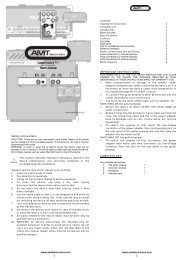
ENG-TS-2-manual - AMT Electronics
ENG-TS-2-manual - AMT Electronics
ENG-TS-2-manual - AMT Electronics

You also want an ePaper? Increase the reach of your titles
YUMPU automatically turns print PDFs into web optimized ePapers that Google loves.
Contents<br />
Important instructions 1<br />
Complete set 1<br />
Introduction 2<br />
Before you start 2<br />
Specifications 2<br />
Power adapter low-voltage contacts arrangement 2<br />
Controls 3<br />
Top panel 3<br />
Left panel 3<br />
Right panel 3<br />
Only for qualified personnel 3<br />
Audio connections and switching 3<br />
Audio connections (2 channels) 3<br />
Audio connections (4 channels) 4<br />
Block diagram 4<br />
Safety instructions<br />
IMPORTANT! There are no user-serviceable components inside the device. The<br />
device repair must be done only by qualified specialists.<br />
WARNING! To avoid possible malfunctions the device must not be exposed to rain<br />
or moisture. Prevent water or other liquids from getting inside the device. Do not<br />
place vessels filled with liquids (such as vases etc.) on top of the device.<br />
This symbol points out important information related to the<br />
device maintenance and operation which can be found in the<br />
accompanying documentation.<br />
IMPORTANT INSTRUCTIONS!<br />
NON-OBSERVANCE OF THE FOLOWING INSTRUCTIONS MIGHT<br />
RESULAT IN YOUR AMPLIFIER OR SPAEAKERS DAMAGE. GUARANTEE<br />
IS VOID IF THE DAMAGES ARE CAUSED BY NON-OBSERVANCE OF<br />
THESE INSTRUCTIONS.<br />
‣ After transportation or storage of the device under under<br />
room temperature in its original packaging for AT LEAST 2<br />
HOURS!<br />
‣ To connect the passive switch to other devices use<br />
exclusively cables intended for such connections.<br />
‣ Under no circumstances use other types of cables such as<br />
for speakers etc.<br />
CONNECTION of the passive switch to power adapter:<br />
‣ Connect the adapter only AFTER all audio connections<br />
have been accomplished!<br />
‣ Before connecting the passive switch to power adapter<br />
make sure that the casing, cables, low-voltage connector<br />
and power plug are free from damages: no cuts, cracks,<br />
dents and so on and are in operable condition.<br />
‣ To connect the passive switch to the power adapter first<br />
insert the low-voltage connector of power adapter into<br />
corresponding socket on the right panel of the switch and<br />
then plug the adapter into the wall outlet.<br />
DISCONNECTION of the passive switch from power adapter:<br />
‣ To disconnect the passive switch from the power adapter<br />
first disconnect the adapter from mains and then<br />
disconnect its low-voltage connector from the socket on<br />
the right panel of the passive switch.<br />
COMPLETE SET<br />
1. Passive switch 1<br />
2. Instruction <strong>manual</strong> 1<br />
3. Packaging 1<br />
4. Warranty card 1<br />
Please read the instruction <strong>manual</strong> carefully.<br />
1. Keep the <strong>manual</strong> at hand.<br />
2. Pay close attention to the warning instructions.<br />
3. Adhere to all maintenance instructions.<br />
4. Use only dry cloth to clean the device which must be<br />
disconnected from the power adapter.<br />
5. Do not place the device next to heat sources, avoid direct<br />
sunlight.<br />
6. Lay the power cable in such a way that it is impossible to be<br />
stepped on. Besides, avoid its contacts with sharp angles etc.<br />
If the plug of the power adapter is used for the device<br />
disconnection from mains, it must be easily accessible.<br />
7. Use only auxiliary devices and accessories recommended by<br />
the manufacturer.<br />
8. Turn the device off during thunderstorms.<br />
9. All works related the device repair must и carried out only by<br />
qualified servicing personnel.<br />
10. IMPORTANT! All servicing instructions are intended<br />
exclusively for qualified personnel. Do not carry out any repair<br />
works not specified in the instruction <strong>manual</strong>. All repair works<br />
are to be carried out by qualified personnel only.<br />
www.amtelectronics.com<br />
www.amtelectronics.com<br />
1 1
INTRODUCTION<br />
<strong>AMT</strong> TRUE SELECTOR <strong>TS</strong>-2 passive switch (further <strong>TS</strong>-2) is intended for studio<br />
use and live performances.<br />
<strong>TS</strong>-2 passive switch is intended for switching of two pedal groups (external signal<br />
processing devices) in order to combine them in a single flexible complex which<br />
allows you to switch from one sound character to another in no time at all.<br />
The <strong>TS</strong>-2 features are as follows:<br />
<strong>TS</strong>-2 has been built with high quality components.<br />
The possibility of modular connection of <strong>TS</strong>-2 passive switches while<br />
configuring the sound system including great number of effects.<br />
The ease of device operation and its commutation with other sound processing<br />
system constituents.<br />
<br />
<br />
The <strong>TS</strong>-2 simplicity ensures its high operational reliability.<br />
The <strong>TS</strong>-2 provides low-voltage power supply to the sound processing effects of<br />
the system by using single power adapter.<br />
Architecture and other features of <strong>TS</strong>-2 passive switch:<br />
The <strong>TS</strong>-2 is a two-channel passive switch.<br />
The <strong>TS</strong>-2 allows the use of two or more external effects modules without<br />
interfering with the switched signals.<br />
If SEND output and RETURN input of any of the channels is not used, the<br />
selection of that channel make the signal from INPUT travel directly to the<br />
output of the passive switch.<br />
Important! <strong>TS</strong>-2 like other top class devices is sensitive to<br />
power source quality. We insist that you use the power<br />
adapter conforming to the quality requirements<br />
(recommended adapters: AC/DC Adapter SA09DC-9V 1,11A or<br />
AC/DC Adapter SA12DC-12V 1,25A).<br />
Specifications<br />
IN DC ADAPTER<br />
Voltage NOM. / MAX.<br />
9 / 12 V<br />
Current NOM. / MAX. 1,25 / 3.0A<br />
OUT 1 DC; OUT 2 DC; OUT 3 DC.<br />
Voltage NOM. / MAX.<br />
9-12 / 15 V<br />
Current NOM. / MAX. 0.8 / 1.25A<br />
Power adapter (optional)<br />
recommended:<br />
AC/DC Adapter SA09DC-<br />
9V 1,11A;<br />
AC/DC Adapter SA12DC-<br />
12V 1,25A.<br />
Dimensions / Weight<br />
Net dimensions (NETTO) (WхHхD). 111х58х73 mm.<br />
NETTO weight<br />
0,23 kg.<br />
Overall dimensions (GROSS) (WхHхD). Appr. 125х83х103mm.<br />
GROSS weight<br />
Appr. 0,3 kg.<br />
Use only external devices and accessories<br />
recommended by the manufacturer.<br />
IT IS STRICTLY PROHIBITED to connect power adapters<br />
with AC output voltage to the IN DC ADAPTER socket!<br />
Before you start<br />
For safe transportation the device was carefully packaged by the manufacturer.<br />
However, if the cardboard packaging is damaged you should immediately inspect<br />
the device for the absence of external damages.<br />
‣ In case of damages do NOT SEND the device to manufacturer,<br />
but inform the seller or transport agency, since otherwise you<br />
will lose the right to damage compensation.<br />
‣ In order to avoid damages during storage and transportation<br />
always use original packing.<br />
‣ Do not allow children to play with the device and packaging<br />
materials.<br />
‣ Please, recycle all packing materials in the way harmless to<br />
the environment.<br />
‣ In order to avoid the device overheating provide a sufficient air<br />
flow around it; do not cover it and do not place near other heat<br />
emitting devices.<br />
‣ Device operation near powerful radio transmitters and sources<br />
of high-frequency signals can result in appreciable<br />
deterioration of sound. In this case increase the distance<br />
between the device and the transmitter and use screened<br />
cables for all interconnections.<br />
CAUTION!<br />
Please be aware that high volume can harm your hearing and / or<br />
damage the dynamic heads of your acoustic system. Before turning<br />
the device on rotate Volume controls to extreme left position<br />
(counter-clockwise). Always try to adhere to moderate volume level.<br />
www.amtelectronics.com<br />
www.amtelectronics.com<br />
2 2
CONTROLS<br />
Front panel<br />
O nly for qualified personnel<br />
The device repair must be done only by qualified experts. If<br />
the device has not been used for a long time, it is necessary<br />
to disconnect the power adapter from mains and remove its<br />
low-voltage connector from the device’s casing.<br />
In order to avoid possible damages or traumas connected<br />
with inflammation or electric short circuit do not allow any<br />
foreign objects or liquids inside the device.<br />
AUDI<br />
O CONNECTIONS AND SWITCHING<br />
CAUTION! All connections are to be carried out only<br />
when the power of the passive switch has been<br />
SWITCHED OFF!<br />
Possible<br />
audio connections between the passive switch and external devices:<br />
1. OUTPUT – passive switch output.<br />
2. Passive switch channel А indicator.<br />
3. RETURN – input for connection of external effects module to channel А<br />
of the passive switch.<br />
4. SEND – signal output to external effects module from channel А of the<br />
passive switch.<br />
5. SEND – signal output to external effects module from channel B of the<br />
passive switch.<br />
6. RETURN – input for connection of external effects module to channel B<br />
of the passive switch.<br />
7. Passive switch channel B indicator.<br />
8. INPUT – passive switch input.<br />
9. FOOT SWITCH for selection of external effects modules connected to<br />
cannels А and В of the passive switch.<br />
Left panel<br />
Right<br />
10. OUT 3 DC –socket for external devices’ power connectors from the<br />
passive switch.<br />
11. OUT 2 DC - socket for external devices’ power connectors from the<br />
passive switch.<br />
pa<br />
nel.<br />
12. OUT 1 DC - socket for external devices’ power connectors from the<br />
passive switch.<br />
13. IN DC ADAPTER – socket for low-voltage connector of the power<br />
adapter.<br />
www.amtelectronics.com<br />
www.amtelectronics.com<br />
3 3
All the mentioned names, titles and trademarks are the property of their owners.<br />
______________________________________________________<br />
<strong>AMT</strong> <strong>Electronics</strong> reserves the right to change the internal and external design of the device<br />
which won’t decrease its consumer properties without preliminary notification. In this<br />
connection the specifications and appearance of the device might differ from the ones<br />
shown in this document.<br />
www.amtelectronics.com<br />
www.amtelectronics.com<br />
4 4