GNUPlot Manual
GNUPlot Manual
GNUPlot Manual

Create successful ePaper yourself
Turn your PDF publications into a flip-book with our unique Google optimized e-Paper software.
70 gnuplot 4.0 36 SET-SHOW<br />
For this to be possible, the surface needs to have ’grid structure’ (see splot datafile (p. 155) about<br />
this), and it has to be drawn with lines or with linespoints.<br />
When hidden3d is set, both the hidden portion of the surface and possibly its contours drawn on the<br />
base (see set contour (p. 61)) as well as the grid will be hidden. Each surface has its hidden parts<br />
removed with respect to itself and to other surfaces, if more than one surface is plotted. Contours<br />
drawn on the surface (set contour surface) don’t work. Labels and arrows are always visible and are<br />
unaffected. The key is also never hidden by the surface.<br />
Functions are evaluated at isoline intersections. The algorithm interpolates linearly between function<br />
points or data points when determining the visible line segments. This means that the appearance of a<br />
function may be different when plotted with hidden3d than when plotted with nohidden3d because<br />
in the latter case functions are evaluated at each sample. Please see set samples (p. 90) and set<br />
isosamples (p. 71) for discussion of the difference.<br />
The algorithm used to remove the hidden parts of the surfaces has some additional features controllable<br />
by this command. Specifying defaults will set them all to their default settings, as detailed below.<br />
If defaults is not given, only explicitly specified options will be influenced: all others will keep their<br />
previous values, so you can turn on/off hidden line removal via set {no}hidden3d, without modifying<br />
the set of options you chose.<br />
The first option, offset, influences the linestyle used for lines on the ’back’ side. Normally, they are<br />
drawn in a linestyle one index number higher than the one used for the front, to make the two sides of<br />
the surface distinguishable. You can specify a different line style offset to add instead of the default 1,<br />
by offset . Option nooffset stands for offset 0, making the two sides of the surface use the<br />
same linestyle.<br />
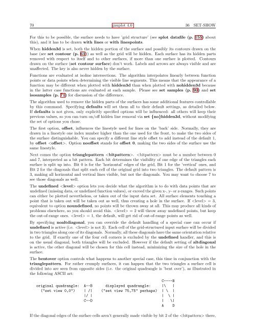
Next comes the option trianglepattern . must be a number between 0<br />
and 7, interpreted as a bit pattern. Each bit determines the visibility of one edge of the triangles each<br />
surface is split up into. Bit 0 is for the ’horizontal’ edges of the grid, Bit 1 for the ’vertical’ ones, and<br />
Bit 2 for the diagonals that split each cell of the original grid into two triangles. The default pattern is<br />
3, making all horizontal and vertical lines visible, but not the diagonals. You may want to choose 7 to<br />
see those diagonals as well.<br />
The undefined option lets you decide what the algorithm is to do with data points that are<br />
undefined (missing data, or undefined function values), or exceed the given x-, y- or z-ranges. Such points<br />
can either be plotted nevertheless, or taken out of the input data set. All surface elements touching a<br />
point that is taken out will be taken out as well, thus creating a hole in the surface. If = 3,<br />
equivalent to option noundefined, no points will be thrown away at all. This may produce all kinds of<br />
problems elsewhere, so you should avoid this. = 2 will throw away undefined points, but keep<br />
the out-of-range ones. = 1, the default, will get rid of out-of-range points as well.<br />
By specifying noaltdiagonal, you can override the default handling of a special case can occur if<br />
undefined is active (i.e. is not 3). Each cell of the grid-structured input surface will be divided<br />
in two triangles along one of its diagonals. Normally, all these diagonals have the same orientation relative<br />
to the grid. If exactly one of the four cell corners is excluded by the undefined handler, and this is<br />
on the usual diagonal, both triangles will be excluded. However if the default setting of altdiagonal<br />
is active, the other diagonal will be chosen for this cell instead, minimizing the size of the hole in the<br />
surface.<br />
The bentover option controls what happens to another special case, this time in conjunction with the<br />
trianglepattern. For rather crumply surfaces, it can happen that the two triangles a surface cell is<br />
divided into are seen from opposite sides (i.e. the original quadrangle is ’bent over’), as illustrated in<br />
the following ASCII art:<br />
C----B<br />
original quadrangle: A--B displayed quadrangle: |\ |<br />
("set view 0,0") | /| ("set view 75,75" perhaps) | \ |<br />
|/ | | \ |<br />
C--D | \|<br />
A D<br />
If the diagonal edges of the surface cells aren’t generally made visible by bit 2 of the there,