Technical Guide - InFocus
Technical Guide - InFocus
Technical Guide - InFocus

Create successful ePaper yourself
Turn your PDF publications into a flip-book with our unique Google optimized e-Paper software.
Projector<br />
IN5542/IN5542c/IN5544/IN5544c<br />
User's Manual (<strong>Technical</strong>)<br />
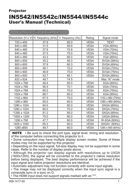
Computer signal examples<br />
Resolution (H x V) H. frequency (kHz) V. frequency (Hz) Rating Signal mode<br />
720 x 400 37.9 85.0 VESA TEXT<br />
640 x 480 31.5 59.9 VESA VGA (60Hz)<br />
640 x 480 37.9 72.8 VESA VGA (72Hz)<br />
640 x 480 37.5 75.0 VESA VGA (75Hz)<br />
640 x 480 43.3 85.0 VESA VGA (85Hz)<br />
800 x 600 35.2 56.3 VESA SVGA (56Hz)<br />
800 x 600 37.9 60.3 VESA SVGA (60Hz)<br />
800 x 600 48.1 72.2 VESA SVGA (72Hz)<br />
800 x 600 46.9 75.0 VESA SVGA (75Hz)<br />
800 x 600 53.7 85.1 VESA SVGA (85Hz)<br />
832 x 624 49.7 74.5 Mac 16” mode<br />
1024 x 768 48.4 60.0 VESA XGA (60Hz)<br />
1024 x 768 56.5 70.1 VESA XGA (70Hz)<br />
1024 x 768 60.0 75.0 VESA XGA (75Hz)<br />
1024 x 768 68.7 85.0 VESA XGA (85Hz)<br />
1152 x 864 67.5 75.0 VESA 1152 x 864 (75Hz)<br />
1280 x 960 60.0 60.0 VESA 1280 x 960 (60Hz)<br />
1280 x 1024 64.0 60.0 VESA SXGA (60Hz)<br />
1280 x 1024 80.0 75.0 VESA SXGA (75Hz)<br />
*1280 x 1024 91.2 85.0 VESA SXGA (85Hz)<br />
*1600 x 1200 75.0 60.0 VESA UXGA (60Hz)<br />
1280 x 768 47.7 60.0 VESA W-XGA (60Hz)<br />
1400 x 1050 65.3 60.0 VESA SXGA+ (60Hz)<br />
1280 x800 49.7 60.0 VESA 1280 x 800 (60Hz)<br />
NOTE • Be sure to check the port type, signal level, timing and resolution<br />
of the computer before connecting this projector to it.<br />
• Some computers may have multiple display screen modes. Some of these<br />
modes may not be supported by this projector.<br />
• Depending on the input signal, full-size display may not be supported in some<br />
cases. Refer to the number of display pixels above.<br />
• Although the projector can display signals with resolutions up to UXGA<br />
(1600x1200), the signal will be converted to the projector’s native resolution<br />
before being displayed. The best display performance will be achieved if the<br />
input signal and native projector resolutions are identical.<br />
• Automatic adjustment may not function correctly with some input signals.<br />
• The image may not be displayed correctly when the input sync signal is a<br />
composite sync or a sync on G.<br />
• The HDMI input does not support signals marked with an "*".<br />
009-1417-00<br />
1
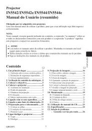
Initial set signals<br />
Initial set signals<br />
The following signals are used for initial settings. The signal timing for some<br />
computer models may be different. In this case, adjust the V POSITION and H<br />
POSITION in the IMAGE menu.<br />
Back porch (B) Front porch (D) Back porch (b) Front porch (d)<br />
Display time (C)<br />
Display time (c)<br />
Data<br />
Data<br />
H. Sync. V. Sync.<br />
Sync (A)<br />
Sync (a)<br />
Computer/ Horizontal signal timing (μs) Computer/ Vertical signal timing (lines)<br />
Signal (A) (B) (C) (D) Signal (a) (b) (c) (d)<br />
TEXT 2.0 3.0 20.3 1.0 TEXT 3 42 400 1<br />
VGA (60Hz) 3.8 1.9 25.4 0.6 VGA (60Hz) 2 33 480 10<br />
VGA (72Hz) 1.3 4.1 20.3 0.8 VGA (72Hz) 3 28 480 9<br />
VGA (75Hz) 2.0 3.8 20.3 0.5 VGA (75Hz) 3 16 480 1<br />
VGA (85Hz) 1.6 2.2 17.8 1.6 VGA (85Hz) 3 25 480 1<br />
SVGA (56Hz) 2.0 3.6 22.2 0.7 SVGA (56Hz) 2 22 600 1<br />
SVGA (60Hz) 3.2 2.2 20.0 1.0 SVGA (60Hz) 4 23 600 1<br />
SVGA (72Hz) 2.4 1.3 16.0 1.1 SVGA (72Hz) 6 23 600 37<br />
SVGA (75Hz) 1.6 3.2 16.2 0.3 SVGA (75Hz) 3 21 600 1<br />
SVGA (85Hz) 1.1 2.7 14.2 0.6 SVGA (85Hz) 3 27 600 1<br />
Mac 16" mode 1.1 3.9 14.5 0.6 Mac 16" mode 3 39 624 1<br />
XGA (60Hz) 2.1 2.5 15.8 0.4 XGA (60Hz) 6 29 768 3<br />
XGA (70Hz) 1.8 1.9 13.7 0.3 XGA (70Hz) 6 29 768 3<br />
XGA (75Hz) 1.2 2.2 13.0 0.2 XGA (75Hz) 3 28 768 1<br />
XGA (85Hz) 1.0 2.2 10.8 0.5 XGA (85Hz) 3 36 768 1<br />
1152 x 864<br />
1152 x 864<br />
1.2 2.4 10.7 0.6<br />
(75Hz)<br />
(75Hz)<br />
3 32 864 1<br />
1280 x 960<br />
1280 x 960<br />
1.0 2.9 11.9 0.9<br />
(60Hz)<br />
(60Hz)<br />
3 36 960 1<br />
SXGA (60Hz) 1.0 2.3 11.9 0.4 SXGA(60Hz) 3 38 1024 1<br />
SXGA (75Hz) 1.1 1.8 9.5 0.1 SXGA (75Hz) 3 38 1024 1<br />
SXGA (85Hz) 1.0 1.4 8.1 0.4 SXGA (85Hz) 3 44 1024 1<br />
UXGA (60Hz) 1.2 1.9 9.9 0.4 UXGA (60Hz) 3 46 1200 1<br />
W-XGA (60Hz) 1.7 2.5 16.0 0.8 W-XGA (60Hz) 3 23 768 1<br />
SXGA+ (60Hz) 1.2 1.9 11.5 0.7 SXGA+ (60Hz) 4 32 1050 3<br />
1280 x<br />
800(60Hz)<br />
1.6 2.4 15.3 0.8<br />
1280 x<br />
800(60Hz)<br />
3 24 800 1<br />
2
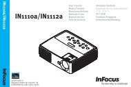
Connection to the ports<br />
Connection to the ports<br />
C<br />
A<br />
B<br />
HDMI<br />
DVI-D<br />
CONTROL IN CONTROL OUT REMOTE<br />
CONTROL<br />
IN<br />
OUT<br />
LAN<br />
D<br />
VIDEO 1<br />
S-VIDEO<br />
COMPUTER IN1 COMPUTER IN2<br />
BNC<br />
MONITOR<br />
OUT<br />
R/Cr/Pr G/Y B/Cb/Pb H V VIDEO 2<br />
AC IN<br />
I<br />
O<br />
Y<br />
Cb/Pb<br />
Cr/Pr<br />
G<br />
F<br />
E<br />
A COMPUTER IN1, B COMPUTER IN2, C MONITOR OUT<br />
D-sub 15pin mini shrink port<br />
• Video signal: RGB separate, Analog, 0.7Vp-p,<br />
75Ω terminated (positive)<br />
• H/V. sync. signal: TTL level (positive/negative)<br />
• Composite sync. signal: TTL level<br />
At RGB signal<br />
Pin Signal Pin Signal<br />
1 Video Red 9 (No connection)<br />
2 Video Green 10 Ground<br />
3 Video Blue 11 (No connection)<br />
4 (No connection) 12 A , B : SDA (DDC data), C : (No connection)<br />
5 Ground 13 H. sync / Composite sync.<br />
6 Ground Red 14 V. sync.<br />
7 Ground Green 15 A , B : SCL (DDC clock), C : (No connection)<br />
8 Ground Blue<br />
D BNC (G/Y, B/Cb/Pb, R/Cr/Pr, H, V)<br />
• BNC port x 5<br />
• Video : Analog 0.7Vp-p, 75Ω terminator<br />
• H/V, sync, : TTL level (positive/negative)<br />
• Composite sync, : TTL level<br />
COMPONENT VIDEO E Y, F Cb/Pb, G Cr/Pr<br />
RCA port x3<br />
• System: 480i@60, 480p@60, 576i@50, 576p@50, 720p@50/60, 1080i@50/60,<br />
1080p@50/60<br />
Port<br />
Signal<br />
Y Component video Y, 1.0±0.1Vp-p, 75Ω terminator with composite sync<br />
Cb/Pb Component video Cb/Pb, 0.7±0.1Vp-p, 75Ω terminator<br />
Cr/Pr Component video Cr/Pr, 0.7±0.1Vp-p, 75Ω terminator<br />
6<br />
11<br />
1<br />
7<br />
12<br />
2<br />
8<br />
13<br />
3<br />
9<br />
14<br />
4<br />
10<br />
15<br />
5<br />
3
Connection to the ports (continued)<br />
HDMI<br />
M<br />
DVI-D<br />
CONTROL IN CONTROL OUT REMOTE<br />
CONTROL<br />
K<br />
N<br />
IN<br />
OUT<br />
L<br />
LAN<br />
VIDEO 1<br />
S-VIDEO<br />
COMPUTER IN1 COMPUTER IN2<br />
BNC<br />
R/Cr/Pr G/Y B/Cb/Pb H V VIDEO 2<br />
Y<br />
Cb/Pb<br />
Cr/Pr<br />
MONITOR<br />
OUT<br />
I<br />
H<br />
J<br />
O<br />
I<br />
AC IN<br />
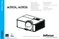
H S-VIDEO<br />
Mini DIN 4pin port<br />
1<br />
3<br />
2<br />
4<br />
Pin<br />
Signal<br />
Color signal 0.286Vp-p (NTSC, burst), 75Ω terminator<br />
1<br />
Color signal 0.300Vp-p (PAL/SECAM, burst) 75Ω terminator<br />
2 Brightness signal, 1.0Vp-p, 75Ω terminator<br />
3 Ground<br />
4 Ground<br />
I VIDEO 1<br />
RCA port<br />
• System: NTSC, PAL, SECAM, PAL-M, PAL-N, NTSC4.43<br />
• 1.0±0.1Vp-p, 75Ω terminator<br />
J VIDEO 2<br />
BNC port<br />
• System: NTSC, PAL, SECAM, PAL-M, PAL-N, NTSC4.43<br />
• 1.0±0.1Vp-p, 75Ω terminator<br />
REMOTE CONTROL K IN L OUT<br />
Ø3.5 stereo mini port<br />
• Connect to the projector's remote control.<br />
CONTROL M IN N OUT<br />
D-sub 9pin plug<br />
1 2 3 4 5<br />
6 7 8 9<br />
• For details of RS-232C communication, please refer to the following RS-232C<br />
Communication in this manual.<br />
Pin Signal Pin Signal Pin Signal<br />
1 (No connection) 4 (No connection) 7 RTS<br />
2 RD 5 Ground 8 CTS<br />
3 TD 6 (No connection) 9 (No connection)<br />
4
Connection to the ports (continued)<br />
O<br />
P<br />
Q<br />
LAN<br />
HDMI<br />
DVI-D<br />
CONTROL IN CONTROL OUT REMOTE<br />
CONTROL<br />
IN<br />
OUT<br />
VIDEO 1<br />
S-VIDEO<br />
COMPUTER IN1 COMPUTER IN2<br />
BNC<br />
MONITOR<br />
OUT<br />
R/Cr/Pr G/Y B/Cb/Pb H V VIDEO 2<br />
Y<br />
Cb/Pb<br />
Cr/Pr<br />
O<br />
I<br />
AC IN<br />
O HDMI<br />
• Type :Digital video connector<br />
18 16 14 12 10 8 6 4 2<br />
19 17 15 13 11 9 7 5 3 1<br />
Pin Signal Pin Signal Pin Signal<br />
1 T.M.D.S. Data2 + 8 T.M.D.S. Data0 Shield 15 SCL<br />
2 T.M.D.S. Data2 Shield 9 T.M.D.S. Data0 - 16 SDA<br />
3 T.M.D.S. Data2 - 10 T.M.D.S. Clock + 17 DDC/CEC Ground<br />
4 T.M.D.S. Data1 + 11 T.M.D.S. Clock Shield 18 +5V Power<br />
5 T.M.D.S. Data1 Shield 12 T.M.D.S. Clock - 19 Hot Plug Detect<br />
6 T.M.D.S. Data1 - 13 CEC<br />
7 T.M.D.S. Data0 + 14 Reserved(N.C. on device)<br />
P DVI-D<br />
DVI-D port (digital to digital)<br />
16 15 14 13 12 11 10 9<br />
24 23 22 21 20 19 18 17<br />
8 7 6 5 4 3 2 1<br />
Pin Signal Pin Signal Pin Signal<br />
1 T.M.D.S. Data2 - 9 T.M.D.S. Data1 - 17 T.M.D.S. Data0 -<br />
2 T.M.D.S. Data2 + 10 T.M.D.S. Data1 + 18 T.M.D.S. Data0 +<br />
3 T.M.D.S. Data2/4 Shield 11 T.M.D.S. Data1/3 Shield 19 T.M.D.S. Data0/5 Shield<br />
4 - 12 - 20 -<br />
5 - 13 - 21 -<br />
6 DDC Clock 14 +5V Power 22 T.M.D.S. Clock Shield<br />
7 DDC Data 15 Ground (for +5V) 23 T.M.D.S. Clock +<br />
8 - 16 Hot Plug Detect 24 T.M.D.S. Clock -<br />
Q LAN<br />
RJ-45 port<br />
1<br />
2<br />
3<br />
4<br />
5<br />
6<br />
7<br />
8<br />
Pin Signal Pin Signal Pin Signal<br />
1 TX+ 4 - 7 -<br />
2 TX- 5 - 8 -<br />
3 RX+ 6 RX-<br />
5
PJLink command<br />
PJLink command<br />
This projector is equipped with PJLink TM Class 1 protocol.<br />
Refer to the following table to control the projector using PJLink TM protocol<br />
commands.<br />
Commands Control Description Parameter or Response<br />
POWR<br />
Power Contorol<br />
0 = Standby<br />
1 = Power On<br />
POWR ? Power Status inquiry<br />
0 = Standby<br />
1 = Power On<br />
2 = Cool Down<br />
INPT Input Source selection<br />
11 = COMPUTER IN 1<br />
12 = COMPUTER IN 2<br />
13 = BNC<br />
21 = COMPONENT<br />
22 = S-VIDEO<br />
23 = VIDEO 1<br />
24 = VIDEO 2<br />
31 = HDMI<br />
32 = DVI-D<br />
INPT ? Input Source inquiry<br />
11 = COMPUTER IN 1<br />
12 = COMPUTER IN 2<br />
13 = BNC<br />
21 = COMPONENT<br />
22 = S-VIDEO<br />
23 = VIDEO 1<br />
24 = VIDEO 2<br />
31 = HDMI<br />
32 = DVI-D<br />
AVMT<br />
AV Mute<br />
30 = BLANK off<br />
31 = BLANK on<br />
AVMT ?<br />
AV Mute inquiry<br />
30 = BLANK off<br />
31 = BLANK on<br />
ERST ? Error Status inquiry<br />
1st byte: Refers to Fan error; one of 0 to 2<br />
2nd byte: Refers to Lamp error; one of 0 to 2<br />
3rd byte: Refers to Temperature error; one of 0 to 2<br />
4th byte: Refers to Cover error; one of 0 to 2<br />
5th byte: Refers to Filter error; one of 0 to 2<br />
6th byte: Refers to Other error; one of 0 to 2<br />
The mearning of 0 to 2 is as given below<br />
0 = Error is not detected; 1 = Warning; 2 = Error<br />
6
PJLink command (continued)<br />
Commands Control Description Parameter or Response<br />
LAMP ? Lamp Status inquiry<br />
1st number (digits 1 to 5): Lamp Time<br />
2nd number : 0 = Lamp off, 1 = Lamp on<br />
INST ? Input Source List inquiry 11 12 13 21 22 23 24 31 32<br />
NAME ? Projector Name inquiry<br />
Responds with the name set in "PROJECTOR NAME"<br />
of "NETWORK"<br />
INF1 ? Manufacturer's Name inquiry INFOCUS<br />
INF2 ? Model Name inquiry<br />
IN5542/IN5542c (XGA model)<br />
IN5544/IN5544c (WXGA model)<br />
INFO ? Other Information inquiry Responds with the factory information and so on<br />
CLSS ? Class Information inquiry 1<br />
NOTE • The password used in PJLink TM is the same as the password as the Web<br />
Browser Control. To use PJLink TM without authentication, do not set any password in<br />
the Web Browser Control.<br />
• For specifications of PJLink TM , see the Japan Business<br />
Machine and Information System Industries Association website.<br />
URL: http://pjlink.jbmia.or.jp/<br />
7
RS-232C Communication<br />
RS-232C Communication<br />
1 2 3 4 5<br />
6 7 8 9<br />
1 2 3 4 5<br />
6 7 8 9<br />
CONTROL port RS-232C cable (Cross) RS-232C port<br />
of the projector<br />
of the computer<br />
- (1) (1) CD<br />
RD (2)<br />
(2) RD<br />
TD (3)<br />
(3) TD<br />
- (4) (4) DTR<br />
GND (5)<br />
(5) GND<br />
- (6) (6) DSR<br />
RTS (7)<br />
(7) RTS<br />
CTS (8)<br />
(8) DTS<br />
- (9) (9) RI<br />
Connecting the cable<br />
1.<br />
2.<br />
8<br />
Turn off the projector and the computer.<br />
Connect the CONTROL port of the projector to the RS-232C port of the<br />
computer by a RS-232C cable (cross). Use a cable which meets the<br />
specifications shown on the previous page.<br />
3.<br />
Turn the computer on, and after the computer has started up, turn the<br />
projector on.<br />
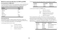
Communications setting<br />
19200bps, 8N1<br />
1. Protocol<br />
Consist of header (7 bytes) + command data (6 bytes).<br />
2. Header<br />
BE + EF + 03 + 06 + 00 + CRC_low + CRC_high<br />
CRC_low : Lower byte of CRC flag for command data<br />
CRC_high : Upper byte of CRC flag for command data<br />
3. Command data<br />
Command data chart<br />
byte_0 byte_1 byte_2 byte_3 byte_4 byte_5<br />
Action Type Setting code<br />
low high low high low high<br />
Action (byte_0 - 1)<br />
Action Classification Content<br />
1 SET Change setting to desired value.<br />
2 GET Read projector internal setup value.<br />
4 INCREMENT Increment setup value by 1.<br />
5 DECREMENT Decrement setup value by 1.<br />
6 EXECUTE Run a command.
RS-232C Communication (continued)<br />
Requesting projector status (Get command)<br />
(1) Send the request code Header + Command data (‘02H’+‘00H’+ type (2<br />
bytes)+‘00H’ +‘00H’) from the computer to the projector.<br />
(2) The projector returns the response code ‘1DH’+ data (2 bytes) to the computer.<br />
Changing the projector settings (Set command)<br />
(1) Send the setting code Header + Command data (‘01H’+‘00H’+ type (2 bytes) +<br />
setting code (2 bytes)) from the computer to the projector.<br />
(2) The projector changes the setting based on the above setting code.<br />
(3) The projector returns the response code ‘06H’ to the computer.<br />
Using the projector default settings (Reset Command)<br />
(1) The computer sends the default setting code Header + Command data<br />
(‘06H’+‘00H’ + type (2 bytes) +‘00H’+‘00H’) to the projector.<br />
(2) The projector changes the specified setting to the default value.<br />
(3) The projector returns the response code ‘06H’ to the computer.<br />
Increasing the projector setting value (Increment command)<br />
(1) The computer sends the increment code Header + Command data<br />
(‘04H’+‘00H’+ type (2 bytes) +‘00H’+‘00H’) to the projector.<br />
(2) The projector in creases the setting value on the above setting code.<br />
(3) The projector returns the response code ‘06H’ to the computer.<br />
Decreasing the projector setting value (Decrement command)<br />
(1) The computer sends the decrement code Header + Command data<br />
(‘05H’+‘00H’+ type (2 bytes) +‘00H’ + ‘00H’) to the projector.<br />
(2) The projector decreases the setting value on the above setting code.<br />
(3) The projector returns the response code ‘06H’ to the computer.<br />
When the projector cannot understand the received command<br />
When the projector cannot understand the received command, the error code ‘15H’<br />
is sent back to the computer.<br />
Sometimes the projector cannot properly receive the command. In this case, the<br />
command is not executed and the error code ‘15H’ is sent back to the computer. If<br />
this error code is returned, send the same command again.<br />
When the projector cannot execute the received command.<br />
When the projector cannot execute the received command, the error code ‘1CH’<br />
+ ‘xxxxH’ is sent back to the computer. When the data length is greater than<br />
indicated by the data length code, the projector will ignore the excess data code.<br />
Conversely when the data length is shorter than indicated by the data length<br />
code, an error code will be returned to the computer.<br />
NOTE • Operation cannot be guaranteed when the projector receives an undefined<br />
command or data.<br />
• Provide an interval of at least 40ms between the response code and any other code.<br />
• The projector outputs test data when the power supply is switched ON, and when the<br />
lamp is lit. Ignore this data.<br />
• Commands are not accepted during warm-up.<br />
9
Command Control via the Network<br />
Communication Port<br />
The following two ports are assigned for command control.<br />
TCP #23<br />
TCP #9715<br />
Command Control via the Network<br />
Command Control Settings<br />
Configure the following items from a web browser when command control is used.<br />
Port Settings<br />
Network Control<br />
Port1 (Port: 23)<br />
Network Control<br />
Port2 (Port: 9715)<br />
Port open<br />
Authentication<br />
Port open<br />
Authentication<br />
Click the [Enable] check box to open [Network<br />
Control Port1 (Port: 23)] to use TCP #23.<br />
Default setting is “Enable”.<br />
Click the [Enable] check box for the<br />
[Authentication] setting when authentication<br />
is required.<br />
Default setting is “Disable”.<br />
Click the [Enable] check box to open [Network<br />
Control Port2 (Port: 9715)] to use TCP<br />
#9715.<br />
Default setting is “Enable”.<br />
Click the [Enable] check box for the<br />
[Authentication] setting when authentication<br />
is required.<br />
Default setting is “Enable”.<br />
When the authentication setting is enabled, the following settings are required.<br />
Security Settings<br />
Network Control<br />
Authentication<br />
Password<br />
Re-enter<br />
Authentication<br />
Password<br />
Enter the desired authentication password.<br />
This setting will be the same for [Network<br />
Control Port1 (Port: 23)] and [Network<br />
Control Port2 (Port: 9715)].<br />
Default setting is blank.<br />
10
Command Control via the Network (continued)<br />
Command Format<br />
[TCP #23]<br />
1. Protocol<br />
Consist of header (7 bytes) + command data (6 bytes)<br />
2. Header<br />
BE + EF + 03 + 06 + 00 + CRC_low + CRC_high<br />
CRC_low: Lower byte of CRC flag for command data<br />
CRC_high: Upper byte of CRC flag for command data<br />
3. Command data<br />
Command data chart<br />
byte_0 byte_1 byte_2 byte_3 byte_4 byte_5<br />
Action Type Setting code<br />
low high low high low high<br />
Action (byte_0 - 1)<br />
Action Classification Content<br />
1 Set Change setting to desired value.<br />
2 Get Read projector internal setup value.<br />
4 Increment Increment setup value by 1.<br />
5 Decrement Decrement setup value by 1.<br />
6 Execute Run a command.<br />
Requesting projector status (Get command)<br />
(1) Send the following request code from the PC to the projector.<br />
Header + Command data (‘02H’ + ‘00H’ + type (2 bytes) + ‘00H’ + ‘00H’)<br />
(2) The projector returns the response code ‘1DH’ + data (2 bytes) to the PC.<br />
Changing the projector settings (Set command)<br />
(1) Send the following setting code from the PC to the projector.<br />
Header + Command data (‘01H’ + ‘00H’ + type (2 bytes) + setting code (2 bytes))<br />
(2) The projector changes the setting based on the above setting code.<br />
(3) The projector returns the response code ‘06H’ to the PC.<br />
Using the projector default settings (Reset Command)<br />
(1) The PC sends the following default setting code to the projector.<br />
Header + Command data (‘06H’ + ‘00H’ + type (2 bytes) + ‘00H’ + ‘00H’)<br />
(2) The projector changes the specified setting to the default value.<br />
(3) The projector returns the response code ‘06H’ to the PC.<br />
Increasing the projector setting value (Increment command)<br />
(1) The PC sends the following increment code to the projector.<br />
Header + Command data (‘04H’ + ‘00H’ + type (2 bytes) + ‘00H’ + ‘00H’)<br />
(2) The projector increases the setting value on the above setting code.<br />
(3) The projector returns the response code ‘06H’ to the PC.<br />
11
Command Control via the Network (continued)<br />
Decreasing the projector setting value (Decrement command)<br />
(1) The PC sends the following decrement code to the projector.<br />
Header + Command data (‘05H’ + ‘00H’ + type (2 bytes) + ‘00H’ + ‘00H’)<br />
(2) The projector decreases the setting value on the above setting code.<br />
(3) The projector returns the response code ‘06H’ to the PC.<br />
When the projector cannot understand the received command<br />
When the projector cannot understand the received command, the error code ‘15H’<br />
is sent back to the PC.<br />
Sometimes the projector cannot properly receive the command. In this case, the<br />
command is not executed and the error code ‘15H’ is sent back to the PC. If this<br />
error code is returned, send the same command again.<br />
When the projector cannot execute the received command.<br />
When the projector cannot execute the received command, the error code ‘1CH’ +<br />
‘xxxxH’ is sent back to the PC.<br />
When the data length is greater than indicated by the data length code, the<br />
projector will ignore the excess data code. Conversely when the data length is<br />
shorter than indicated by the data length code, an error code will be returned to<br />
the PC.<br />
When authentication error occurred.<br />
When authentication error occurred, the error code the ‘1FH’ + ‘0400H’ is sent<br />
back to the PC.<br />
NOTE • Operation cannot be guaranteed when the projector receives an undefined<br />
command or data.<br />
• Provide an interval of at least 40ms between the response code and any other code.<br />
• Commands are not accepted during warm-up.<br />
[TCP #9715]<br />
1. Protocol<br />
Consist of header (1 byte) + data length (1 byte) + command data (13 bytes) +<br />
check sum (1 bytes) + connection ID (1 byte).<br />
2. Header<br />
02, Fixed<br />
3. Data Length<br />
Network control commands byte length (0D, Fixed)<br />
4. Command data<br />
Network control commands that start with BE EF (13bytes).<br />
5. Check Sum<br />
This is the value to make zero on the addition of the lower 8 bits from the header<br />
to the checksum.<br />
6. Connection ID<br />
Random value from 0 to 255 (This value is attached to the reply data).<br />
12
Command Control via the Network (continued)<br />
7. Reply Data<br />
The connection ID (the data is same as the connection ID data on the sending<br />
data format) is attached to the Network control commands reply data.<br />
ACK reply: ‘06H’ + ‘xxH’<br />
NAK reply: ‘15H’ + ‘xxH’<br />
Error reply: ‘1CH’ + ‘xxxxH’ + ‘xxH’<br />
Data reply: ‘1DH’ + ‘xxxxH’ + ‘xxH’<br />
Projector busy reply: ‘1FH’ + ‘xxxxH’ + ‘xxH’<br />
Authentication error reply: ‘1FH’ + ‘0400H’ + ‘xxH’<br />
(‘xxH’ : connection ID)<br />
Automatic Connection Break<br />
The TCP connection will be automatically disconnected after there is no<br />
communication for 30 seconds after being established.<br />
Authentication<br />
The projector does not accept commands without authentication success<br />
when authentication is enabled. The projector uses a challenge response type<br />
authentication with an MD5 (Message Digest 5) algorithm. When the projector<br />
is using a LAN, a random 8 bytes will be returned if authentication is enabled.<br />
Combine this received 8 bytes and the authentication password and digest this<br />
data with the MD5 algorithm and add this in front of the commands to send.<br />
Following is a sample if the authentication password is set to “password” and the<br />
random 8 bytes are “a572f60c”.<br />
1) Select the projector.<br />
2) Receive the random 8 bytes “a572f60c” from the projector.<br />
3) Combine the random 8 bytes “a572f60c” and the authentication password<br />
“password” and it becomes “a572f60cpassword”.<br />
4) Use this combination “a572f60cpassword” with MD5 algorithm.<br />
It will become “e3d97429adffa11bce1f7275813d4bde”.<br />
5) Add “e3d97429adffa11bce1f7275813d4bde” in front of the commands and<br />
send the data.<br />
Send “e3d97429adffa11bce1f7275813d4bde”+command.<br />
6) When the sending data is correct, the command will be performed and the<br />
reply data will be returned. Otherwise, an authentication error will be returned.<br />
NOTE • During the transmission of the second or subsequent commands, the<br />
authentication data can be omitted when using the same connection.<br />
13
Daisy Chain Communication<br />
Daisy Chain Communication<br />
Transmitting side<br />
1 2 3 4 5<br />
6 7 8 9<br />
Recieving side<br />
1 2 3 4 5<br />
6 7 8 9<br />
CONTROL OUT port<br />
in Projector<br />
1.Communications setting<br />
Set the same communication settings (selecting from options below) on the<br />
CONTROL terminal for transmitting and receiving side connected with a RS-232C<br />
cable.<br />
Baud rate: 4800 / 9600 / 19200 / 38400 bps<br />
Parity NONE / ODD / EVEN<br />
Data bit: 8 bit (fixed)<br />
Start bit: 1 bit (fixed)<br />
Stop bit: 1 bit (fixed)<br />
2.Commands available only for daisy chain<br />
communication<br />
The projector supports the following commands only for daisy chain.<br />
(1) Control the projector (Set/Increment/Decrement/Execute)<br />
(2) Get the projector’s status (Get)<br />
(3) Get the number of connected projectors<br />
(4) Set the communication Group identification and Communication ID.<br />
(5) Get the communication Group identification and Communication ID.<br />
3.Command format<br />
Protocol<br />
Consist of header data (7 bytes) + command data (6 bytes)<br />
Header<br />
BE + EF + Packet_Type + 06 + Group + ID + Checksum<br />
Data chart<br />
Support Command Packet_Type Group ID<br />
Control the projector ‘83H’ 0~16 0~64<br />
Get the projector’s status ‘83H’ 1~16 1~64<br />
Get the number of connected projectors ‘84H’ 0 0<br />
Set the communication Group<br />
‘85H’ 1~16 1~64<br />
identification and Communication ID<br />
Get the communication Group<br />
identification and Communication ID<br />
‘86H’ 0 0<br />
14<br />
RS-232C cable (Cross)<br />
- (1) (1) CD<br />
RD (2)<br />
(2) RD<br />
TD (3)<br />
(3) TD<br />
- (4) (4) DTR<br />
GND (5)<br />
(5) GND<br />
- (6) (6) DSR<br />
RTS (7)<br />
(7) RTS<br />
CTS (8)<br />
(8) DTS<br />
- (9) (9) RI<br />
CONTROL IN<br />
port in Projector
Daisy Chain Communication<br />
Calculation of Checksum<br />
Sum up all of 12 bytes except the Checksum, then make the bit inversion of the<br />
lowest byte of the total, and add 1 to the inverted byte. The calculated result is<br />
the Checksum data.<br />
Exp. Communication Group: A / Communication ID: 1<br />
Header data (7 bytes)<br />
Command data (6 bytes)<br />
Header Packet Data Size Group ID Checksum Action Type Setting<br />
Type<br />
Code<br />
BE EF 83 06 01 01 66 01 00 00 60 01 00<br />
BE + EF + 83 + 06 + 01 + 01 + 01 + 00 + 00 + 60 + 01 + 00 = ‘029AH’<br />
The lowest byte of ‘029AH’ is ‘9AH’ (1001 1010). Making the bit inversion of the<br />
‘9AH’ gets ‘65H’ (0110 0101), then, add 1. The calculated checksum is ’66H’.<br />
Group and ID Settings<br />
This daisy chain command can adjust the control range by using the Group<br />
identification and ID.<br />
Group ID Direction note<br />
1~16 1~64 Individual control The command is available to the projectors with<br />
the same Group identification and ID numbers and<br />
command setting.<br />
1~16 0 Designated control<br />
according to the<br />
Group identification<br />
0 1~64 Designated control<br />
according to the ID<br />
The command is available to the projectors with the<br />
same Group identification and command setting.<br />
The command is available to the projectors with the<br />
same ID number and command setting.<br />
0 0 Unlimited. The command is available to the all projectors.<br />
15
Daisy Chain Communication<br />
Command data<br />
1 Controlling projector<br />
byte_0 byte_1 byte_2 byte_3 byte_4 byte_5<br />
Action Type Setting Code<br />
low high low high low high<br />
Action (byte_0-1)<br />
Action Classification Content<br />
1 Set Change setting to desired value.<br />
4 Increment Increment setup value by 1.<br />
5 Decrement Decrement setup value by 1.<br />
6 Execute Run a command.<br />
Note: For the Type and Setting Code, see the RS-232C communication/<br />
Network command table (20).<br />
2 Getting the projector’s status<br />
byte_0 byte_1 byte_2 byte_3 byte_4 byte_5<br />
Action Type Connection ID<br />
low high low high low high<br />
Action (byte_0-1)<br />
Action Classification Content<br />
2 Get Read projector internal setup value.<br />
Connection ID (byte_4-5)<br />
Connection ID<br />
Content<br />
0~255 This value is attached to the reply data.<br />
3 Other commands<br />
byte_0 byte_1 byte_2 byte_3 byte_4 byte_5<br />
Action Target Number Connection ID<br />
low high low high low high<br />
Support Command Action Target Number Connection ID<br />
Get the number of connected projectors 2 0 0~255<br />
Set the communication Group<br />
1 1~65535 0~255<br />
identification and Communication ID<br />
Get the communication Group<br />
identification and Communication ID<br />
2 1~65535 0~255<br />
16
Daisy Chain Communication<br />
Command data<br />
Requesting projector status (Get command)<br />
(1) Send the following request code from the PC to the projector.<br />
Header + Command data (‘02H’ + ‘00H’ + type (2 bytes) + connection ID (2<br />
bytes))<br />
(2) The projector returns the response code to the PC.<br />
‘9DH’ + ‘02H’ + connection ID (2 bytes) + data (2 bytes)<br />
When the projector cannot understand the received command, the error code<br />
is sent back to the PC.<br />
‘95H’ + ‘02H’ + connection ID (2 bytes) + ‘00H’ + ‘00H’<br />
When the projector cannot execute the received command, the error code is<br />
sent back to the PC.<br />
‘9CH’ + ‘02H’ + connection ID (2 bytes) + error code (2 bytes)<br />
Action (byte_0-1)<br />
Error Code<br />
Error Code<br />
Content<br />
0 The command was not accepted because the projector connected to PC<br />
was busy.<br />
1 Communication error occurred between projectors.<br />
2 The command was not accepted because the designated projector was<br />
not found.<br />
Changing the projector settings (Set command)<br />
(1) Send the following request code from the PC to the projector.<br />
Header + Command data (‘01H’ + ‘00H’ + type (2 bytes) + setting code (2 bytes))<br />
(2) The projector changes the setting based on the above setting code.<br />
(3) Projector does not send out the response data.<br />
Using the projector default settings (Reset Command)<br />
(1) The PC sends the following default setting code to the projector.<br />
Header + Command data (‘06H’ + ‘00H’ + type (2 bytes) + ‘00H’ + ‘00H’)<br />
(2) The projector changes the specified setting to the default value.<br />
(3) Projector does not send out the response data.<br />
Increasing the projector setting value (Increment command)<br />
(1) The PC sends the following increment code to the projector.<br />
Header + Command data (‘04H’ + ‘00H’ + type (2 bytes) + ‘00H’ + ‘00H’)<br />
(2) The projector increases the setting value on the above setting code.<br />
(3) Projector does not send out the response data.<br />
Decreasing the projector setting value (Decrement command)<br />
(1) The PC sends the following decrement code to the projector.<br />
Header + Command data (‘05H’ + ‘00H’ + type (2 bytes) + ‘00H’ + ‘00H’)<br />
(2) The projector decreases the setting value on the above setting code.<br />
(3) Projector does not send out the response data.<br />
17
Daisy Chain Communication<br />
Get the number of connected projectors<br />
(1) Send the following request code from the PC to the projector.<br />
Header + Command data (‘02H’ + ‘00H’ + ‘00H’ + ‘00H’ + connection ID (2 bytes))<br />
(2) The projector returns the response code to the PC.<br />
‘9EH’ + ‘04H’ + connection ID (2 bytes) + number of projectors (2 bytes) + group (1<br />
byte) + ID (1 byte)<br />
When the projector cannot understand the received command, the error code is<br />
sent back to the PC.<br />
‘96H’ + ‘04H’ + connection ID (2 bytes) + ‘00H’ + ‘00H’ + ‘00H’ + ‘00H’<br />
When the projector cannot execute the received command, the error code is sent<br />
back to the PC.<br />
‘9FH’ + ‘06H’ + connection ID (2 bytes) + position number of projector having an<br />
error* (2 bytes) + group (1 byte) + ID (1 byte) + error code (2 bytes)<br />
*The position number is counted from the projector connected to PC directly,<br />
which has No.1 as position number. Then, the next one is No.2 and so on.<br />
Error Code<br />
Error Code<br />
Content<br />
0 The command was not accepted because the projector connected to PC<br />
was busy.<br />
1 Communication error occurred between projectors.<br />
Set the communication Group identification and<br />
Communication ID<br />
(1) Send the following setting code from the PC to the projector.<br />
Header + Command data (‘01H’ + ‘00H’ + target number (2 bytes) + connection ID<br />
(2 bytes))<br />
(2) The projector changes the group and ID setting based on the above setting<br />
code.<br />
(3) Projector does not send out the response data.<br />
18
Daisy Chain Communication<br />
Get the communication Group identification and<br />
Communication ID<br />
(1) Send the following request code from the PC to the projector.<br />
Header + Command data (‘02H’ + ‘00H’ + target number (2 bytes) + connection ID<br />
(2 bytes))<br />
(2) The projector returns the response code to the PC.<br />
‘90H’ + ‘04H’ + connection ID (2 bytes) + target number (2 bytes) + group (1 byte)<br />
+ ID (1 byte)<br />
When the projector cannot understand the received command, the error code is<br />
sent back to the PC.<br />
‘97H’ + ‘04H’ + connection ID (2 bytes) + ‘00H’ + ‘00H’ + ‘00H’ + ‘00H’<br />
When the projector cannot execute the received command, the error code is sent<br />
back to the PC.<br />
‘91H’ + ‘06H’ + connection ID (2 bytes) + position number of projector having an<br />
error* (2 bytes) + group (1 byte) + ID (1 byte) + error code (2 bytes)<br />
* The position number is counted from the projector connected to PC directly,<br />
which has No.1 as position number. Then, the next one is No.2 and so on.<br />
Error Code<br />
Error Code<br />
Content<br />
0 The command was not accepted because the projector connected to PC<br />
was busy.<br />
1 Communication error occurred between projectors.<br />
2 The command was not accepted because the designated projector was<br />
not found.<br />
NOTE • During transmission of the second or subsequent commands, the<br />
authentication data can be omitted when using the same connection.<br />
• Commands are not accepted during warm-up.<br />
•To use the daisy chain communication, select DAISY CHAIN in the OPTION<br />
>COMMUNICATION TYPE submenu in the OSD (On Screen Display) (User's<br />
Manual (detailed) - Operating <strong>Guide</strong>)<br />
19
RS-232C Communication / Network command table<br />
20<br />
RS-232C Communication / Network command table<br />
Names Operation Type Header<br />
Command Data<br />
CRC Action Type Setting Code<br />
Power Set OFF BE EF 03 06 00 2A D3 01 00 00 60 00 00<br />
ON BE EF 03 06 00 BA D2 01 00 00 60 01 00<br />
Get BE EF 03 06 00 19 D3 02 00 00 60 00 00<br />
(Example Return)<br />
00 00 01 00 02 00<br />
(Off) (On) (Cool Down)<br />
Input Source Set COMPUTER IN 1 BE EF 03 06 00 FE D2 01 00 00 20 00 00<br />
COMPUTER IN 2 BE EF 03 06 00 3E D0 01 00 00 20 04 00<br />
HDMI BE EF 03 06 00 0E D2 01 00 00 20 03 00<br />
VIDEO 1 BE EF 03 06 00 6E D3 01 00 00 20 01 00<br />
S-VIDEO BE EF 03 06 00 9E D3 01 00 00 20 02 00<br />
COMPONENT BE EF 03 06 00 AE D1 01 00 00 20 05 00<br />
BNC BE EF 03 06 00 CE D0 01 00 00 20 07 00<br />
DVI-D BE EF 03 06 00 AE D4 01 00 00 20 09 00<br />
VIDEO 2 BE EF 03 06 00 5E D4 01 00 00 20 0A 00<br />
Get BE EF 03 06 00 CD D2 02 00 00 20 00 00<br />
Error Status Get BE EF 03 06 00 D9 D8 02 00 20 60 00 00<br />
(Example Return)<br />
00 00 01 00 02 00 03 00<br />
(Normal) (Cover error) (Fan error) (Lamp error)<br />
04 00 05 00<br />
(Temp error) (Air flow error)<br />
07 00 08 00 0F 00 10 00<br />
(Cold error) (Filter error) (Shutter error) (Lens Shift error)<br />
BRIGHTNESS Get BE EF 03 06 00 89 D2 02 00 03 20 00 00<br />
Increment BE EF 03 06 00 EF D2 04 00 03 20 00 00<br />
Decrement BE EF 03 06 00 3E D3 05 00 03 20 00 00<br />
CONTRAST Get BE EF 03 06 00 FD D3 02 00 04 20 00 00<br />
Increment BE EF 03 06 00 9B D3 04 00 04 20 00 00<br />
Decrement BE EF 03 06 00 4A D2 05 00 04 20 00 00<br />
PICTURE MODE Set NORMAL BE EF 03 06 00 23 F6 01 00 BA 30 00 00<br />
CINEMA BE EF 03 06 00 B3 F7 01 00 BA 30 01 00<br />
DYNAMIC BE EF 03 06 00 E3 F4 01 00 BA 30 04 00<br />
BOARD (BLACK) BE EF 03 06 00 E3 EF 01 00 BA 30 20 00<br />
BOARD (GREEN) BE EF 03 06 00 73 EE 01 00 BA 30 21 00<br />
WHITE BOARD BE EF 03 06 00 83 EE 01 00 BA 30 22 00<br />
DAY TIME BE EF 03 06 00 E3 C7 01 00 BA 30 40 00<br />
CUSTOM BE EF 03 06 00 E3 FB 01 00 BA 30 10 00<br />
Get BE EF 03 06 00 10 F6 02 00 BA 30 00 00<br />
GAMMA Set 1 DEFAULT BE EF 03 06 00 07 E9 01 00 A1 30 20 00<br />
2 DEFAULT BE EF 03 06 00 97 E8 01 00 A1 30 21 00<br />
3 DEFAULT BE EF 03 06 00 67 E8 01 00 A1 30 22 00<br />
4 DEFAULT BE EF 03 06 00 F7 E9 01 00 A1 30 23 00<br />
5 DEFAULT BE EF 03 06 00 C7 EB 01 00 A1 30 24 00<br />
6 DEFAULT BE EF 03 06 00 57 EA 01 00 A1 30 25 00<br />
1 CUSTOM BE EF 03 06 00 07 FD 01 00 A1 30 10 00<br />
2 CUSTOM BE EF 03 06 00 97 FC 01 00 A1 30 11 00<br />
3 CUSTOM BE EF 03 06 00 67 FC 01 00 A1 30 12 00<br />
4 CUSTOM BE EF 03 06 00 F7 FD 01 00 A1 30 13 00
RS-232C Communication / Network command table<br />
Names Operation Type Header<br />
Command Data<br />
CRC Action Type Setting Code<br />
GAMMA Set 5 CUSTOM BE EF 03 06 00 C7 FF 01 00 A1 30 14 00<br />
6 CUSTOM BE EF 03 06 00 57 FE 01 00 A1 30 15 00<br />
Get BE EF 03 06 00 F4 F0 02 00 A1 30 00 00<br />
User Gamma Pattern Set Off BE EF 03 06 00 FB FA 01 00 80 30 00 00<br />
9step Gray Scale BE EF 03 06 00 6B FB 01 00 80 30 01 00<br />
15step Gray Scale BE EF 03 06 00 9B FB 01 00 80 30 02 00<br />
Ramp BE EF 03 06 00 0B FA 01 00 80 30 03 00<br />
Get BE EF 03 06 00 C8 FA 02 00 80 30 00 00<br />
User Gamma Point 1 Get BE EF 03 06 00 08 FE 02 00 90 30 00 00<br />
Increment BE EF 03 06 00 6E FE 04 00 90 30 00 00<br />
Decrement BE EF 03 06 00 BF FF 05 00 90 30 00 00<br />
User Gamma Point 2 Get BE EF 03 06 00 F4 FF 02 00 91 30 00 00<br />
Increment BE EF 03 06 00 92 FF 04 00 91 30 00 00<br />
Decrement BE EF 03 06 00 43 FE 05 00 91 30 00 00<br />
User Gamma Point 3 Get BE EF 03 06 00 B0 FF 02 00 92 30 00 00<br />
Increment BE EF 03 06 00 D6 FF 04 00 92 30 00 00<br />
Decrement BE EF 03 06 00 07 FE 05 00 92 30 00 00<br />
User Gamma Point 4 Get BE EF 03 06 00 4C FE 02 00 93 30 00 00<br />
Increment BE EF 03 06 00 2A FE 04 00 93 30 00 00<br />
Decrement BE EF 03 06 00 FB FF 05 00 93 30 00 00<br />
User Gamma Point 5 Get BE EF 03 06 00 38 FF 02 00 94 30 00 00<br />
Increment BE EF 03 06 00 5E FF 04 00 94 30 00 00<br />
Decrement BE EF 03 06 00 8F FE 05 00 94 30 00 00<br />
User Gamma Point 6 Get BE EF 03 06 00 C4 FE 02 00 95 30 00 00<br />
Increment BE EF 03 06 00 A2 FE 04 00 95 30 00 00<br />
Decrement BE EF 03 06 00 73 FF 05 00 95 30 00 00<br />
User Gamma Point 7 Get BE EF 03 06 00 80 FE 02 00 96 30 00 00<br />
Increment BE EF 03 06 00 E6 FE 04 00 96 30 00 00<br />
Decrement BE EF 03 06 00 37 FF 05 00 96 30 00 00<br />
User Gamma Point 8 Get BE EF 03 06 00 7C FF 02 00 97 30 00 00<br />
Increment BE EF 03 06 00 1A FF 04 00 97 30 00 00<br />
Decrement BE EF 03 06 00 CB FE 05 00 97 30 00 00<br />
COLOR TEMP Set 1 HIGH BE EF 03 06 00 0B F5 01 00 B0 30 03 00<br />
2 MID BE EF 03 06 00 9B F4 01 00 B0 30 02 00<br />
3 LOW BE EF 03 06 00 6B F4 01 00 B0 30 01 00<br />
4 Hi-BRIGHT-1 BE EF 03 06 00 3B F2 01 00 B0 30 08 00<br />
5 Hi-BRIGHT-2 BE EF 03 06 00 AB F3 01 00 B0 30 09 00<br />
6 Hi-BRIGHT-3 BE EF 03 06 00 5B F3 01 00 B0 30 0A 00<br />
1 CUSTOM (HIGH) BE EF 03 06 00 CB F8 01 00 B0 30 13 00<br />
2 CUSTOM (MID) BE EF 03 06 00 5B F9 01 00 B0 30 12 00<br />
3 CUSTOM (LOW) BE EF 03 06 00 AB F9 01 00 B0 30 11 00<br />
4 CUSTOM BE EF 03 06 00 FB FF 01 00 B0 30 18 00<br />
(Hi-BRIGHT-1)<br />
5 CUSTOM BE EF 03 06 00 6B FE 01 00 B0 30 19 00<br />
(Hi-BRIGHT-2)<br />
6 CUSTOM BE EF 03 06 00 9B FE 01 00 B0 30 1A 00<br />
(Hi-BRIGHT-3)<br />
Get BE EF 03 06 00 C8 F5 02 00 B0 30 00 00<br />
21
RS-232C Communication / Network command table<br />
Names Operation Type Header<br />
Command Data<br />
CRC Action Type Setting Code<br />
COLOR TEMP GAIN R Get BE EF 03 06 00 34 F4 02 00 B1 30 00 00<br />
Increment BE EF 03 06 00 52 F4 04 00 B1 30 00 00<br />
Decrement BE EF 03 06 00 83 F5 05 00 B1 30 00 00<br />
COLOR TEMP GAIN G Get BE EF 03 06 00 70 F4 02 00 B2 30 00 00<br />
Increment BE EF 03 06 00 16 F4 04 00 B2 30 00 00<br />
Decrement BE EF 03 06 00 C7 F5 05 00 B2 30 00 00<br />
COLOR TEMP GAIN B Get BE EF 03 06 00 8C F5 02 00 B3 30 00 00<br />
Increment BE EF 03 06 00 EA F5 04 00 B3 30 00 00<br />
Decrement BE EF 03 06 00 3B F4 05 00 B3 30 00 00<br />
COLOR TEMP OFFSET<br />
R<br />
COLOR TEMP OFFSET<br />
G<br />
COLOR TEMP OFFSET<br />
B<br />
Get BE EF 03 06 00 04 F5 02 00 B5 30 00 00<br />
Increment BE EF 03 06 00 62 F5 04 00 B5 30 00 00<br />
Decrement BE EF 03 06 00 B3 F4 05 00 B5 30 00 00<br />
Get BE EF 03 06 00 40 F5 02 00 B6 30 00 00<br />
Increment BE EF 03 06 00 26 F5 04 00 B6 30 00 00<br />
Decrement BE EF 03 06 00 F7 F4 05 00 B6 30 00 00<br />
Get BE EF 03 06 00 BC F4 02 00 B7 30 00 00<br />
Increment BE EF 03 06 00 DA F4 04 00 B7 30 00 00<br />
Decrement BE EF 03 06 00 0B F5 05 00 B7 30 00 00<br />
COLOR Get BE EF 03 06 00 B5 72 02 00 02 22 00 00<br />
Increment BE EF 03 06 00 D3 72 04 00 02 22 00 00<br />
Decrement BE EF 03 06 00 02 73 05 00 02 22 00 00<br />
COLOR Reset Execute BE EF 03 06 00 80 D0 06 00 0A 70 00 00<br />
TINT Get BE EF 03 06 00 49 73 02 00 03 22 00 00<br />
Increment BE EF 03 06 00 2F 73 04 00 03 22 00 00<br />
Decrement BE EF 03 06 00 FE 72 05 00 03 22 00 00<br />
TINT Reset Execute BE EF 03 06 00 7C D1 06 00 0B 70 00 00<br />
SHARPNESS Get BE EF 03 06 00 F1 72 02 00 01 22 00 00<br />
Increment BE EF 03 06 00 97 72 04 00 01 22 00 00<br />
Decrement BE EF 03 06 00 46 73 05 00 01 22 00 00<br />
SHARPNESS Reset Execute BE EF 03 06 00 C4 D0 06 00 09 70 00 00<br />
ACTIVE IRIS Set PRESENTATION BE EF 03 06 00 5B 2E 01 00 04 33 11 00<br />
THEATER BE EF 03 06 00 CB 2F 01 00 04 33 10 00<br />
MANUAL BE EF 03 06 00 CB 3B 01 00 04 33 20 00<br />
Get BE EF 03 06 00 38 22 02 00 04 33 00 00<br />
MANUAL IRIS Get BE EF 03 06 00 B0 22 02 00 02 33 00 00<br />
Increment BE EF 03 06 00 D6 22 04 00 02 33 00 00<br />
Decrement BE EF 03 06 00 07 23 05 00 02 33 00 00<br />
MY MEMORY Load Set 1 BE EF 03 06 00 0E D7 01 00 14 20 00 00<br />
2 BE EF 03 06 00 9E D6 01 00 14 20 01 00<br />
3 BE EF 03 06 00 6E D6 01 00 14 20 02 00<br />
4 BE EF 03 06 00 FE D7 01 00 14 20 03 00<br />
MY MEMORY Save Set 1 BE EF 03 06 00 F2 D6 01 00 15 20 00 00<br />
2 BE EF 03 06 00 62 D7 01 00 15 20 01 00<br />
3 BE EF 03 06 00 92 D7 01 00 15 20 02 00<br />
4 BE EF 03 06 00 02 D6 01 00 15 20 03 00<br />
PROGRESSIVE Set OFF BE EF 03 06 00 4A 72 01 00 07 22 00 00<br />
TV BE EF 03 06 00 DA 73 01 00 07 22 01 00<br />
FILM BE EF 03 06 00 2A 73 01 00 07 22 02 00<br />
Get BE EF 03 06 00 79 72 02 00 07 22 00 00<br />
22
Names Operation Type Header<br />
RS-232C Communication / Network command table<br />
Command Data<br />
CRC Action Type Setting Code<br />
3D-YCS Set OFF BE EF 03 06 00 E6 70 01 00 0A 22 00 00<br />
MOVIE BE EF 03 06 00 76 71 01 00 0A 22 01 00<br />
STILL IMAGE BE EF 03 06 00 86 71 01 00 0A 22 02 00<br />
Get BE EF 03 06 00 D5 70 02 00 0A 22 00 00<br />
VIDEO NR Set LOW BE EF 03 06 00 26 72 01 00 06 22 01 00<br />
MID BE EF 03 06 00 D6 72 01 00 06 22 02 00<br />
HIGH BE EF 03 06 00 46 73 01 00 06 22 03 00<br />
Get BE EF 03 06 00 85 73 02 00 06 22 00 00<br />
ASPECT Set NORMAL BE EF 03 06 00 5E DD 01 00 08 20 10 00<br />
4:3 BE EF 03 06 00 9E D0 01 00 08 20 00 00<br />
16:9 BE EF 03 06 00 0E D1 01 00 08 20 01 00<br />
16:10 *2 BE EF 03 06 00 3E D6 01 00 08 20 0A 00<br />
14:9 BE EF 03 06 00 CE D6 01 00 08 20 09 00<br />
SMALL *1 BE EF 03 06 00 FE D1 01 00 08 20 02 00<br />
NATIVE *2 BE EF 03 06 00 5E D7 01 00 08 20 08 00<br />
FULL *2 BE EF 03 06 00 5E C9 01 00 08 20 20 00<br />
Get BE EF 03 06 00 AD D0 02 00 08 20 00 00<br />
OVER SCAN Get BE EF 03 06 00 91 70 02 00 09 22 00 00<br />
Increment BE EF 03 06 00 F7 70 04 00 09 22 00 00<br />
Decrement BE EF 03 06 00 26 71 05 00 09 22 00 00<br />
OVER SCAN Reset Execute BE EF 03 06 00 EC D9 06 00 27 70 00 00<br />
V POSITION Get BE EF 03 06 00 0D 83 02 00 00 21 00 00<br />
Increment BE EF 03 06 00 6B 83 04 00 00 21 00 00<br />
Decrement BE EF 03 06 00 BA 82 05 00 00 21 00 00<br />
V POSITION Reset Execute BE EF 03 06 00 E0 D2 06 00 02 70 00 00<br />
H POSITION Get BE EF 03 06 00 F1 82 02 00 01 21 00 00<br />
Increment BE EF 03 06 00 97 82 04 00 01 21 00 00<br />
Decrement BE EF 03 06 00 46 83 05 00 01 21 00 00<br />
H POSITION Reset Execute BE EF 03 06 00 1C D3 06 00 03 70 00 00<br />
H PHASE Get BE EF 03 06 00 49 83 02 00 03 21 00 00<br />
Increment BE EF 03 06 00 2F 83 04 00 03 21 00 00<br />
Decrement BE EF 03 06 00 FE 82 05 00 03 21 00 00<br />
H SIZE Get BE EF 03 06 00 B5 82 02 00 02 21 00 00<br />
Increment BE EF 03 06 00 D3 82 04 00 02 21 00 00<br />
Decrement BE EF 03 06 00 02 83 05 00 02 21 00 00<br />
H SIZE Reset Execute BE EF 03 06 00 68 D2 06 00 04 70 00 00<br />
AUTO ADJUST Execute BE EF 03 06 00 91 D0 06 00 0A 20 00 00<br />
COLOR SPACE Set AUTO BE EF 03 06 00 0E 72 01 00 04 22 00 00<br />
RGB BE EF 03 06 00 9E 73 01 00 04 22 01 00<br />
SMPTE240 BE EF 03 06 00 6E 73 01 00 04 22 02 00<br />
REC709 BE EF 03 06 00 FE 72 01 00 04 22 03 00<br />
REC601 BE EF 03 06 00 CE 70 01 00 04 22 04 00<br />
Get BE EF 03 06 00 3D 72 02 00 04 22 00 00<br />
COMPONENT Set COMPONENT BE EF 03 06 00 4A D7 01 00 17 20 00 00<br />
SCART RGB BE EF 03 06 00 DA D6 01 00 17 20 01 00<br />
Get BE EF 03 06 00 79 D7 02 00 17 20 00 00<br />
*1 IN5542/IN5542c only. *2 IN5544/IN5544c only.<br />
23
RS-232C Communication / Network command table<br />
Names Operation Type Header<br />
Command Data<br />
CRC Action Type Setting Code<br />
S-VIDEO FORMAT Set AUTO BE EF 03 06 00 E6 70 01 00 12 22 0A 00<br />
NTSC BE EF 03 06 00 86 74 01 00 12 22 04 00<br />
PAL BE EF 03 06 00 16 75 01 00 12 22 05 00<br />
SECAM BE EF 03 06 00 16 70 01 00 12 22 09 00<br />
NTSC4.43 BE EF 03 06 00 26 77 01 00 12 22 02 00<br />
M-PAL BE EF 03 06 00 86 71 01 00 12 22 08 00<br />
N-PAL BE EF 03 06 00 76 74 01 00 12 22 07 00<br />
Get BE EF 03 06 00 75 76 02 00 12 22 00 00<br />
VIDEO 1 FORMAT Set AUTO BE EF 03 06 00 A2 70 01 00 11 22 0A 00<br />
NTSC BE EF 03 06 00 C2 74 01 00 11 22 04 00<br />
PAL BE EF 03 06 00 52 75 01 00 11 22 05 00<br />
SECAM BE EF 03 06 00 52 70 01 00 11 22 09 00<br />
NTSC4.43 BE EF 03 06 00 62 77 01 00 11 22 02 00<br />
M-PAL BE EF 03 06 00 C2 71 01 00 11 22 08 00<br />
N-PAL BE EF 03 06 00 32 74 01 00 11 22 07 00<br />
Get BE EF 03 06 00 31 76 02 00 11 22 00 00<br />
VIDEO 2 FORMAT Set AUTO BE EF 03 06 00 86 72 01 00 1A 22 0A 00<br />
NTSC BE EF 03 06 00 E6 76 01 00 1A 22 04 00<br />
PAL BE EF 03 06 00 76 77 01 00 1A 22 05 00<br />
SECAM BE EF 03 06 00 76 72 01 00 1A 22 09 00<br />
NTSC4.43 BE EF 03 06 00 46 75 01 00 1A 22 02 00<br />
M-PAL BE EF 03 06 00 E6 73 01 00 1A 22 08 00<br />
N-PAL BE EF 03 06 00 16 76 01 00 1A 22 07 00<br />
Get BE EF 03 06 00 15 74 02 00 1A 22 00 00<br />
HDMI FORMAT Set AUTO BE EF 03 06 00 BA 77 01 00 13 22 00 00<br />
VIDEO BE EF 03 06 00 2A 76 01 00 13 22 01 00<br />
COMPUTER BE EF 03 06 00 DA 76 01 00 13 22 02 00<br />
Get BE EF 03 06 00 89 77 02 00 13 22 00 00<br />
DVI-D FORMAT Set AUTO BE EF 03 06 00 62 74 01 00 19 22 00 00<br />
VIDEO BE EF 03 06 00 F2 75 01 00 19 22 01 00<br />
COMPUTER BE EF 03 06 00 02 75 01 00 19 22 02 00<br />
Get BE EF 03 06 00 51 74 02 00 19 22 00 00<br />
HDMI RANGE Set AUTO BE EF 03 06 00 86 D8 01 00 22 20 00 00<br />
NORMAL BE EF 03 06 00 16 D9 01 00 22 20 01 00<br />
ENHANCED BE EF 03 06 00 E6 D9 01 00 22 20 02 00<br />
Get BE EF 03 06 00 B5 D8 02 00 22 20 00 00<br />
DVI-D RANGE Set AUTO BE EF 03 06 00 FE D4 01 00 20 20 10 00<br />
NORMAL BE EF 03 06 00 3E D9 01 00 20 20 00 00<br />
ENHANCED BE EF 03 06 00 AE D8 01 00 20 20 01 00<br />
Get BE EF 03 06 00 0D D9 02 00 20 20 00 00<br />
COMPUTER IN 1 Set SYNC ON G OFF BE EF 03 06 00 5E D7 01 00 10 20 02 00<br />
AUTO BE EF 03 06 00 CE D6 01 00 10 20 03 00<br />
Get BE EF 03 06 00 0D D6 02 00 10 20 00 00<br />
COMPUTER IN 2 Set SYNC ON G OFF BE EF 03 06 00 A2 D6 01 00 11 20 02 00<br />
AUTO BE EF 03 06 00 32 D7 01 00 11 20 03 00<br />
Get BE EF 03 06 00 F1 D7 02 00 11 20 00 00<br />
BNC Set SYNC ON G OFF BE EF 03 06 00 86 D4 01 00 1A 20 02 00<br />
AUTO BE EF 03 06 00 16 D5 01 00 1A 20 03 00<br />
Get BE EF 03 06 00 D5 D5 02 00 1A 20 00 00<br />
24
RS-232C Communication / Network command table<br />
Names Operation Type Header<br />
Command Data<br />
CRC Action Type Setting Code<br />
FRAME LOCK -<br />
COMPUTER IN 1<br />
FRAME LOCK -<br />
COMPUTER IN 2<br />
Set OFF BE EF 03 06 00 3B C2 01 00 50 30 00 00<br />
ON BE EF 03 06 00 AB C3 01 00 50 30 01 00<br />
Get BE EF 03 06 00 08 C2 02 00 50 30 00 00<br />
Set OFF BE EF 03 06 00 0B C3 01 00 54 30 00 00<br />
ON BE EF 03 06 00 9B C2 01 00 54 30 00 00<br />
Get BE EF 03 06 00 38 C3 02 00 54 30 00 00<br />
FRAME LOCK - BNC Set OFF BE EF 03 06 00 4F C3 01 00 57 30 00 00<br />
ON BE EF 03 06 00 DF C2 01 00 57 30 01 00<br />
Get BE EF 03 06 00 7C C3 02 00 57 30 00 00<br />
FRAME LOCK - HDMI Set OFF BE EF 03 06 00 7F C2 01 00 53 30 00 00<br />
ON BE EF 03 06 00 EF C3 01 00 53 30 01 00<br />
Get BE EF 03 06 00 4C C2 02 00 53 30 00 00<br />
FRAME LOCK - DVI-D Set OFF BE EF 03 06 00 A7 C1 01 00 59 30 00 00<br />
ON BE EF 03 06 00 37 C0 01 00 59 30 01 00<br />
Get BE EF 03 06 00 94 C1 02 00 59 30 00 00<br />
KEYSTONE V Get BE EF 03 06 00 B9 D3 02 00 07 20 00 00<br />
Increment BE EF 03 06 00 DF D3 04 00 07 20 00 00<br />
Decrement BE EF 03 06 00 0E D2 05 00 07 20 00 00<br />
KEYSTONE V Reset Execute BE EF 03 06 00 08 D0 06 00 0C 70 00 00<br />
AUTO KEYSTONE V<br />
Execute BE EF 03 06 00 E5 D1 06 00 0D 20 00 00<br />
EXECUTE<br />
AUTO KEYSTONE V Set OFF BE EF 03 06 00 EA D1 01 00 0F 20 00 00<br />
ON BE EF 03 06 00 7A D0 01 00 0F 20 01 00<br />
Get BE EF 03 06 00 D9 D1 02 00 0F 20 00 00<br />
KEYSTONE H Get BE EF 03 06 00 E9 D0 02 00 0B 20 00 00<br />
Increment BE EF 03 06 00 8F D0 04 00 0B 20 00 00<br />
Decrement BE EF 03 06 00 5E D1 05 00 0B 20 00 00<br />
KEYSTONE H Reset Execute BE EF 03 06 00 98 D8 06 00 20 70 00 00<br />
ECO MODE Set NORMAL BE EF 03 06 00 3B 23 01 00 00 33 00 00<br />
ECO BE EF 03 06 00 AB 22 01 00 00 33 01 00<br />
Get BE EF 03 06 00 08 23 02 00 00 33 00 00<br />
MIRROR Set NORMAL BE EF 03 06 00 C7 D2 01 00 01 30 00 00<br />
MONITOR OUT -<br />
COMPUTER IN 1<br />
MONITOR OUT -<br />
COMPUTER IN 2<br />
MONITOR OUT -<br />
BNC<br />
H:INVERT BE EF 03 06 00 57 D3 01 00 01 30 01 00<br />
V:INVERT BE EF 03 06 00 A7 D3 01 00 01 30 02 00<br />
H&V:INVERT BE EF 03 06 00 37 D2 01 00 01 30 03 00<br />
Get BE EF 03 06 00 F4 D2 02 00 01 30 00 00<br />
Set COMPUTER IN 1 BE EF 03 06 00 3E F4 01 00 B0 20 00 00<br />
COMPUTER IN 2 BE EF 03 06 00 FE F6 01 00 B0 20 04 00<br />
BNC BE EF 03 06 00 0E F6 01 00 B0 20 07 00<br />
OFF BE EF 03 06 00 CE B5 01 00 B0 20 FF 00<br />
Get BE EF 03 06 00 0D F4 02 00 B0 20 00 00<br />
Set COMPUTER IN 1 BE EF 03 06 00 0E F5 01 00 B4 20 00 00<br />
COMPUTER IN 2 BE EF 03 06 00 CE F7 01 00 B4 20 04 00<br />
BNC BE EF 03 06 00 3E F7 01 00 B4 20 07 00<br />
OFF BE EF 03 06 00 FE B4 01 00 B4 20 FF 00<br />
Get BE EF 03 06 00 3D F5 02 00 B4 20 00 00<br />
Set COMPUTER IN 1 BE EF 03 06 00 4A F5 01 00 B7 20 00 00<br />
COMPUTER IN 2 BE EF 03 06 00 8A F7 01 00 B7 20 04 00<br />
BNC BE EF 03 06 00 7A F7 01 00 B7 20 07 00<br />
OFF BE EF 03 06 00 BA B4 01 00 B7 20 FF 00<br />
Get BE EF 03 06 00 79 F5 02 00 B7 20 00 00<br />
25
RS-232C Communication / Network command table<br />
Names Operation Type Header<br />
Command Data<br />
CRC Action Type Setting Code<br />
MONITOR OUT -<br />
HDMI<br />
MONITOR OUT -<br />
DVI-D<br />
MONITOR OUT -<br />
COMPONENT<br />
MONITOR OUT -<br />
S-VIDEO<br />
MONITOR OUT -<br />
VIDEO 1<br />
MONITOR OUT -<br />
VIDEO 2<br />
MONITOR OUT -<br />
STANDBY<br />
Set COMPUTER IN 1 BE EF 03 06 00 7A F4 01 00 B3 20 00 00<br />
COMPUTER IN 2 BE EF 03 06 00 BA F6 01 00 B3 20 04 00<br />
BNC BE EF 03 06 00 4A F6 01 00 B3 20 07 00<br />
OFF BE EF 03 06 00 8A B5 01 00 B3 20 FF 00<br />
Get BE EF 03 06 00 49 F4 02 00 B3 20 00 00<br />
Set COMPUTER IN 1 BE EF 03 06 00 A2 F7 01 00 B9 20 00 00<br />
COMPUTER IN 2 BE EF 03 06 00 62 F5 01 00 B9 20 04 00<br />
BNC BE EF 03 06 00 92 F5 01 00 B9 20 07 00<br />
OFF BE EF 03 06 00 52 B6 01 00 B9 20 FF 00<br />
Get BE EF 03 06 00 91 F7 02 00 B9 20 00 00<br />
Set COMPUTER IN 1 BE EF 03 06 00 F2 F4 01 00 B5 20 00 00<br />
COMPUTER IN 2 BE EF 03 06 00 32 F6 01 00 B5 20 04 00<br />
BNC BE EF 03 06 00 C2 F6 01 00 B5 20 07 00<br />
OFF BE EF 03 06 00 02 B5 01 00 B5 20 FF 00<br />
Get BE EF 03 06 00 C1 F4 02 00 B5 20 00 00<br />
Set COMPUTER IN 1 BE EF 03 06 00 86 F5 01 00 B2 20 00 00<br />
COMPUTER IN 2 BE EF 03 06 00 46 F7 01 00 B2 20 04 00<br />
BNC BE EF 03 06 00 B6 F7 01 00 B2 20 07 00<br />
OFF BE EF 03 06 00 76 B4 01 00 B2 20 FF 00<br />
Get BE EF 03 06 00 B5 F5 02 00 B2 20 00 00<br />
Set COMPUTER IN 1 BE EF 03 06 00 C2 F5 01 00 B1 20 00 00<br />
COMPUTER IN 2 BE EF 03 06 00 02 F7 01 00 B1 20 04 00<br />
BNC BE EF 03 06 00 F2 F7 01 00 B1 20 07 00<br />
OFF BE EF 03 06 00 32 B4 01 00 B1 20 FF 00<br />
Get BE EF 03 06 00 F1 F5 02 00 B1 20 00 00<br />
Set COMPUTER IN 1 BE EF 03 06 00 E6 F7 01 00 BA 20 00 00<br />
COMPUTER IN 2 BE EF 03 06 00 26 F5 01 00 BA 20 04 00<br />
BNC BE EF 03 06 00 D6 F5 01 00 BA 20 07 00<br />
OFF BE EF 03 06 00 16 B6 01 00 BA 20 FF 00<br />
Get BE EF 03 06 00 D5 F7 02 00 BA 20 00 00<br />
Set COMPUTER IN 1 BE EF 03 06 00 2A F7 01 00 BF 20 00 00<br />
COMPUTER IN 2 BE EF 03 06 00 EA F5 01 00 BF 20 04 00<br />
BNC BE EF 03 06 00 1A F5 01 00 BF 20 07 00<br />
OFF BE EF 03 06 00 DA B6 01 00 BF 20 FF 00<br />
Get BE EF 03 06 00 19 F7 02 00 BF 20 00 00<br />
LANGUAGE Set ENGLISH BE EF 03 06 00 F7 D3 01 00 05 30 00 00<br />
FRANÇAIS BE EF 03 06 00 67 D2 01 00 05 30 01 00<br />
DEUTSCH BE EF 03 06 00 97 D2 01 00 05 30 02 00<br />
ESPAÑOL BE EF 03 06 00 07 D3 01 00 05 30 03 00<br />
ITALIANO BE EF 03 06 00 37 D1 01 00 05 30 04 00<br />
NORSK BE EF 03 06 00 A7 D0 01 00 05 30 05 00<br />
NEDERLANDS BE EF 03 06 00 57 D0 01 00 05 30 06 00<br />
PORTUGUÊS BE EF 03 06 00 C7 D1 01 00 05 30 07 00<br />
BE EF 03 06 00 A7 D5 01 00 05 30 09 00<br />
BE EF 03 06 00 37 DE 01 00 05 30 10 00<br />
BE EF 03 06 00 57 D5 01 00 05 30 0A 00<br />
SVENSKA BE EF 03 06 00 C7 D4 01 00 05 30 0B 00<br />
PYCCKNN BE EF 03 06 00 F7 D6 01 00 05 30 0C 00<br />
SUOMI BE EF 03 06 00 67 D7 01 00 05 30 0D 00<br />
26
RS-232C Communication / Network command table<br />
Names Operation Type Header<br />
Command Data<br />
CRC Action Type Setting Code<br />
LANGUAGE Set POLSKI BE EF 03 06 00 97 D7 01 00 05 30 0E 00<br />
TÜRKÇE BE EF 03 06 00 07 D6 01 00 05 30 0F 00<br />
Get BE EF 03 06 00 C4 D3 02 00 05 30 00 00<br />
MENU POSITION V Get BE EF 03 06 00 40 D7 02 00 16 30 00 00<br />
Increment BE EF 03 06 00 26 D7 04 00 16 30 00 00<br />
Decrement BE EF 03 06 00 F7 D6 05 00 16 30 00 00<br />
MENU POSITION V<br />
Execute BE EF 03 06 00 A8 C7 06 00 44 70 00 00<br />
Reset<br />
MENU POSITION H Get BE EF 03 06 00 04 D7 02 00 15 30 00 00<br />
Increment BE EF 03 06 00 62 D7 04 00 15 30 00 00<br />
Decrement BE EF 03 06 00 B3 D6 05 00 15 30 00 00<br />
MENU POSITION H<br />
Execute BE EF 03 06 00 DC C6 06 00 43 70 00 00<br />
Reset<br />
BLANK Set MyScreen BE EF 03 06 00 FB CA 01 00 00 30 20 00<br />
ORIGINAL BE EF 03 06 00 FB E2 01 00 00 30 40 00<br />
BLUE BE EF 03 06 00 CB D3 01 00 00 30 03 00<br />
WHITE BE EF 03 06 00 6B D0 01 00 00 30 05 00<br />
BLACK BE EF 03 06 00 9B D0 01 00 00 30 06 00<br />
Get BE EF 03 06 00 08 D3 02 00 00 30 00 00<br />
BLANK On/Off Set OFF BE EF 03 06 00 FB D8 01 00 20 30 00 00<br />
ON BE EF 03 06 00 6B D9 01 00 20 30 01 00<br />
Get BE EF 03 06 00 C8 D8 02 00 20 30 00 00<br />
START UP Set MyScreen BE EF 03 06 00 CB CB 01 00 04 30 20 00<br />
ORIGINAL BE EF 03 06 00 0B D2 01 00 04 30 00 00<br />
OFF BE EF 03 06 00 9B D3 01 00 04 30 01 00<br />
Get BE EF 03 06 00 38 D2 02 00 04 30 00 00<br />
MyScreen LOCK Set OFF BE EF 03 06 00 3B EF 01 00 C0 30 00 00<br />
ON BE EF 03 06 00 AB EE 01 00 C0 30 01 00<br />
Get BE EF 03 06 00 08 EF 02 00 C0 30 00 00<br />
MESSAGE Set OFF BE EF 03 06 00 8F D6 01 00 17 30 00 00<br />
ON BE EF 03 06 00 1F D7 01 00 17 30 01 00<br />
Get BE EF 03 06 00 BC D6 02 00 17 30 00 00<br />
TEMPLATE Set TEST PATTERN BE EF 03 06 00 43 D9 01 00 22 30 00 00<br />
DOT-LINE 1 BE EF 03 06 00 D3 D8 01 00 22 30 01 00<br />
DOT-LINE 2 BE EF 03 06 00 23 D8 01 00 22 30 02 00<br />
DOT-LINE 3 BE EF 03 06 00 B3 D9 01 00 22 30 03 00<br />
DOT-LINE 4 BE EF 03 06 00 83 DB 01 00 22 30 04 00<br />
Get BE EF 03 06 00 70 D9 02 00 22 30 00 00<br />
TEMPLATE On/Off Set OFF BE EF 03 06 00 BF D8 01 00 23 30 00 00<br />
ON BE EF 03 06 00 2F D9 01 00 23 30 01 00<br />
Get BE EF 03 06 00 8C D8 02 00 23 30 00 00<br />
CLOSED CAPTION<br />
DISPLAY<br />
CLOSED CAPTION<br />
MODE<br />
Set OFF BE EF 03 06 00 FA 62 01 00 00 37 00 00<br />
ON BE EF 03 06 00 6A 63 01 00 00 37 01 00<br />
Get BE EF 03 06 00 C9 62 02 00 00 37 00 00<br />
Set CAPTIONS BE EF 03 06 00 06 63 01 00 01 37 00 00<br />
TEXT BE EF 03 06 00 96 62 01 00 01 37 01 00<br />
Get BE EF 03 06 00 35 63 02 00 01 37 00 00<br />
27
RS-232C Communication / Network command table<br />
Names Operation Type Header<br />
Command Data<br />
CRC Action Type Setting Code<br />
CLOSED CAPTION<br />
CHANNEL<br />
SOURCE SKIP<br />
COMPUTER IN 1<br />
SOURCE SKIP<br />
COMPUTER IN 2<br />
28<br />
SOURCE SKIP<br />
BNC<br />
SOURCE SKIP<br />
HDMI<br />
SOURCE SKIP<br />
DVI-D<br />
SOURCE SKIP<br />
COMPONENT<br />
SOURCE SKIP<br />
S-VIDEO<br />
SOURCE SKIP<br />
VIDEO 1<br />
SOURCE SKIP<br />
VIDEO 2<br />
Set 1 BE EF 03 06 00 D2 62 01 00 02 37 01 00<br />
2 BE EF 03 06 00 22 62 01 00 02 37 02 00<br />
3 BE EF 03 06 00 B2 63 01 00 02 37 03 00<br />
4 BE EF 03 06 00 82 61 01 00 02 37 04 00<br />
Get BE EF 03 06 00 71 63 02 00 02 37 00 00<br />
Set NORMAL BE EF 03 06 00 FE 78 01 00 20 22 00 00<br />
SKIP BE EF 03 06 00 6E 79 01 00 20 22 01 00<br />
Get BE EF 03 06 00 CD 78 02 00 20 22 00 00<br />
Set NORMAL BE EF 03 06 00 CE 79 01 00 24 22 00 00<br />
SKIP BE EF 03 06 00 5E 78 01 00 24 22 01 00<br />
Get BE EF 03 06 00 FD 79 02 00 24 22 00 00<br />
Set NORMAL BE EF 03 06 00 8A 79 01 00 27 22 00 00<br />
SKIP BE EF 03 06 00 1A 78 01 00 27 22 01 00<br />
Get BE EF 03 06 00 B9 79 02 00 27 22 00 00<br />
Set NORMAL BE EF 03 06 00 BA 78 01 00 23 22 00 00<br />
SKIP BE EF 03 06 00 2A 79 01 00 23 22 01 00<br />
Get BE EF 03 06 00 89 78 02 00 23 22 00 00<br />
Set NORMAL BE EF 03 06 00 62 7B 01 00 29 22 00 00<br />
SKIP BE EF 03 06 00 F2 7A 01 00 29 22 01 00<br />
Get BE EF 03 06 00 51 7B 02 00 29 22 00 00<br />
Set NORMAL BE EF 03 06 00 32 78 01 00 25 22 00 00<br />
SKIP BE EF 03 06 00 A2 79 01 00 25 22 01 00<br />
Get BE EF 03 06 00 01 78 02 00 25 22 00 00<br />
Set NORMAL BE EF 03 06 00 46 79 01 00 22 22 00 00<br />
SKIP BE EF 03 06 00 D6 78 01 00 22 22 01 00<br />
Get BE EF 03 06 00 75 79 02 00 22 22 00 00<br />
Set NORMAL BE EF 03 06 00 02 79 01 00 21 22 00 00<br />
SKIP BE EF 03 06 00 92 78 01 00 21 22 01 00<br />
Get BE EF 03 06 00 31 79 02 00 21 22 00 00<br />
Set NORMAL BE EF 03 06 00 26 7B 01 00 2A 22 00 00<br />
SKIP BE EF 03 06 00 B6 7A 01 00 2A 22 01 00<br />
Get BE EF 03 06 00 15 7B 02 00 2A 22 00 00<br />
AUTO SEARCH Set OFF BE EF 03 06 00 B6 D6 01 00 16 20 00 00<br />
ON BE EF 03 06 00 26 D7 01 00 16 20 01 00<br />
Get BE EF 03 06 00 85 D6 02 00 16 20 00 00<br />
DIRECT ON Set OFF BE EF 03 06 00 3B 89 01 00 20 31 00 00<br />
ON BE EF 03 06 00 AB 88 01 00 20 31 01 00<br />
Get BE EF 03 06 00 08 89 02 00 20 31 00 00<br />
AUTO OFF Get BE EF 03 06 00 08 86 02 00 10 31 00 00<br />
Increment BE EF 03 06 00 6E 86 04 00 10 31 00 00<br />
Decrement BE EF 03 06 00 BF 87 05 00 10 31 00 00<br />
SHUTTER TIMER Set 1h BE EF 03 06 00 27 92 01 00 06 24 01 00<br />
3h BE EF 03 06 00 47 93 01 00 06 24 03 00<br />
6h BE EF 03 06 00 17 90 01 00 06 24 06 00<br />
Get BE EF 03 06 00 84 93 02 00 06 24 00 00<br />
LAMP TIME LOW Get BE EF 03 06 00 C2 FF 02 00 90 10 00 00<br />
LAMP TIME HIIGH Get BE EF 03 06 00 2A FD 02 00 9E 10 00 00<br />
LAMP TIME Reset Execute BE EF 03 06 00 58 DC 06 00 30 70 00 00<br />
FILTER TIME LOW Get BE EF 03 06 00 C2 F0 02 00 A0 10 00 00<br />
FILTER TIME HIGH Get BE EF 03 06 00 D6 FC 02 00 9F 10 00 00<br />
FILTER TIME Reset Execute BE EF 03 06 00 98 C6 06 00 40 70 00 00
RS-232C Communication / Network command table<br />
Names Operation Type Header<br />
Command Data<br />
CRC Action Type Setting Code<br />
MY BUTTON-1 Set COMPUTER IN 1 BE EF 03 06 00 3A 33 01 00 00 36 00 00<br />
COMPUTER IN 2 BE EF 03 06 00 FA 31 01 00 00 36 04 00<br />
BNC BE EF 03 06 00 0A 31 01 00 00 36 07 00<br />
HDMI BE EF 03 06 00 CA 33 01 00 00 36 03 00<br />
DVI-D BE EF 03 06 00 6A 35 01 00 00 36 09 00<br />
COMPONENT BE EF 03 06 00 6A 30 01 00 00 36 05 00<br />
S-VIDEO BE EF 03 06 00 5A 32 01 00 00 36 02 00<br />
VIDEO 1 BE EF 03 06 00 AA 32 01 00 00 36 01 00<br />
VIDEO 2 BE EF 03 06 00 9A 35 01 00 00 36 0A 00<br />
INFORMATION BE EF 03 06 00 FA 3E 01 00 00 36 10 00<br />
AUTO KEYSTONE BE EF 03 06 00 6A 3F 01 00 00 36 11 00<br />
EXECUTE<br />
MY MEMORY BE EF 03 06 00 9A 3F 01 00 00 36 12 00<br />
ACTIVE IRIS BE EF 03 06 00 AA 3D 01 00 00 36 15 00<br />
PICTURE MODE BE EF 03 06 00 0A 3E 01 00 00 36 13 00<br />
FILTER RESET BE EF 03 06 00 3A 3C 01 00 00 36 14 00<br />
TEMPLATE BE EF 03 06 00 CA 39 01 00 00 36 1B 00<br />
PbyP SWAP BE EF 03 06 00 5A 38 01 00 00 36 1A 00<br />
LENS MEMORY-1 BE EF 03 06 00 CA 27 01 00 00 36 33 00<br />
LENS MEMORY-2 BE EF 03 06 00 FA 25 01 00 00 36 34 00<br />
LENS MEMORY-3 BE EF 03 06 00 6A 24 01 00 00 36 35 00<br />
MY IMAGE BE EF 03 06 00 5A 3D 01 00 00 36 16 00<br />
Get BE EF 03 06 00 09 33 02 00 00 36 00 00<br />
MY BUTTON-2 Set COMPUTER IN 1 BE EF 03 06 00 C6 32 01 00 01 36 00 00<br />
COMPUTER IN 2 BE EF 03 06 00 06 30 01 00 01 36 04 00<br />
BNC BE EF 03 06 00 F6 30 01 00 01 36 07 00<br />
HDMI BE EF 03 06 00 36 32 01 00 01 36 03 00<br />
DVI-D BE EF 03 06 00 96 34 01 00 01 36 09 00<br />
COMPONENT BE EF 03 06 00 96 31 01 00 01 36 05 00<br />
S-VIDEO BE EF 03 06 00 A6 33 01 00 01 36 02 00<br />
VIDEO 1 BE EF 03 06 00 56 33 01 00 01 36 01 00<br />
VIDEO 2 BE EF 03 06 00 66 34 01 00 01 36 0A 00<br />
INFORMATION BE EF 03 06 00 06 3F 01 00 01 36 10 00<br />
AUTO KEYSTONE BE EF 03 06 00 96 3E 01 00 01 36 11 00<br />
EXECUTE<br />
MY MEMORY BE EF 03 06 00 66 3E 01 00 01 36 12 00<br />
ACTIVE IRIS BE EF 03 06 00 56 3C 01 00 01 36 15 00<br />
PICTURE MODE BE EF 03 06 00 F6 3F 01 00 01 36 13 00<br />
FILTER RESET BE EF 03 06 00 C6 3D 01 00 01 36 14 00<br />
TEMPLATE BE EF 03 06 00 36 38 01 00 01 36 1B 00<br />
PbyP SWAP BE EF 03 06 00 A6 39 01 00 01 36 1A 00<br />
LENS MEMORY-1 BE EF 03 06 00 36 26 01 00 01 36 33 00<br />
LENS MEMORY-2 BE EF 03 06 00 06 24 01 00 01 36 34 00<br />
LENS MEMORY-3 BE EF 03 06 00 96 25 01 00 01 36 35 00<br />
MY IMAGE BE EF 03 06 00 A6 3C 01 00 01 36 16 00<br />
Get BE EF 03 06 00 F5 32 02 00 01 36 00 00<br />
MY BUTTON-3 Set COMPUTER IN 1 BE EF 03 06 00 82 32 01 00 02 36 00 00<br />
COMPUTER IN 2 BE EF 03 06 00 42 30 01 00 02 36 04 00<br />
BNC BE EF 03 06 00 B2 30 01 00 02 36 07 00<br />
HDMI BE EF 03 06 00 72 32 01 00 02 36 03 00<br />
29
RS-232C Communication / Network command table<br />
Names Operation Type Header<br />
Command Data<br />
CRC Action Type Setting Code<br />
MY BUTTON-3 Set DVI-D BE EF 03 06 00 D2 34 01 00 02 36 09 00<br />
COMPONENT BE EF 03 06 00 D2 31 01 00 02 36 05 00<br />
S-VIDEO BE EF 03 06 00 E2 33 01 00 02 36 02 00<br />
VIDEO 1 BE EF 03 06 00 12 33 01 00 02 36 01 00<br />
VIDEO 2 BE EF 03 06 00 22 34 01 00 02 36 0A 00<br />
INFORMATION BE EF 03 06 00 42 3F 01 00 02 36 10 00<br />
AUTO KEYSTONE BE EF 03 06 00 D2 3E 01 00 02 36 11 00<br />
EXECUTE<br />
MY MEMORY BE EF 03 06 00 22 3E 01 00 02 36 12 00<br />
ACTIVE IRIS BE EF 03 06 00 12 3C 01 00 02 36 15 00<br />
PICTURE MODE BE EF 03 06 00 B2 3F 01 00 02 36 13 00<br />
FILTER RESET BE EF 03 06 00 82 3D 01 00 02 36 14 00<br />
TEMPLATE BE EF 03 06 00 72 38 01 00 02 36 1B 00<br />
PbyP SWAP BE EF 03 06 00 E2 39 01 00 02 36 1A 00<br />
LENS MEMORY-1 BE EF 03 06 00 72 26 01 00 02 36 33 00<br />
LENS MEMORY-2 BE EF 03 06 00 42 24 01 00 02 36 34 00<br />
LENS MEMORY-3 BE EF 03 06 00 D2 25 01 00 02 36 35 00<br />
MY IMAGE BE EF 03 06 00 E2 3C 01 00 02 36 16 00<br />
Get BE EF 03 06 00 B1 32 02 00 02 36 00 00<br />
MY BUTTON-4 Set COMPUTER IN 1 BE EF 03 06 00 7E 33 01 00 03 36 00 00<br />
COMPUTER IN 2 BE EF 03 06 00 BE 31 01 00 03 36 04 00<br />
BNC BE EF 03 06 00 4E 31 01 00 03 36 07 00<br />
HDMI BE EF 03 06 00 8E 33 01 00 03 36 03 00<br />
DVI-D BE EF 03 06 00 2E 35 01 00 03 36 09 00<br />
30<br />
COMPONENT BE EF 03 06 00 2E 30 01 00 03 36 05 00<br />
S-VIDEO BE EF 03 06 00 1E 32 01 00 03 36 02 00<br />
VIDEO 1 BE EF 03 06 00 EE 32 01 00 03 36 01 00<br />
VIDEO 2 BE EF 03 06 00 DE 35 01 00 03 36 0A 00<br />
INFORMATION BE EF 03 06 00 BE 3E 01 00 03 36 10 00<br />
AUTO KEYSTONE BE EF 03 06 00 2E 3F 01 00 03 36 11 00<br />
EXECUTE<br />
MY MEMORY BE EF 03 06 00 DE 3F 01 00 03 36 12 00<br />
ACTIVE IRIS BE EF 03 06 00 EE 3D 01 00 03 36 15 00<br />
PICTURE MODE BE EF 03 06 00 4E 3E 01 00 03 36 13 00<br />
FILTER RESET BE EF 03 06 00 7E 3C 01 00 03 36 14 00<br />
TEMPLATE BE EF 03 06 00 8E 39 01 00 03 36 1B 00<br />
PbyP SWAP BE EF 03 06 00 1E 38 01 00 03 36 1A 00<br />
LENS MEMORY-1 BE EF 03 06 00 8E 27 01 00 03 36 33 00<br />
LENS MEMORY-2 BE EF 03 06 00 BE 25 01 00 03 36 34 00<br />
LENS MEMORY-3 BE EF 03 06 00 2E 24 01 00 03 36 35 00<br />
MY IMAGE BE EF 03 06 00 1E 3D 01 00 03 36 16 00<br />
Get BE EF 03 06 00 4D 33 02 00 03 36 00 00<br />
MY SOURCE Set COMPUTER IN 1 BE EF 03 06 00 FA 38 01 00 20 36 00 00<br />
COMPUTER IN 2 BE EF 03 06 00 3A 3A 01 00 20 36 04 00<br />
BNC BE EF 03 06 00 CA 3A 01 00 20 36 07 00<br />
HDMI BE EF 03 06 00 0A 38 01 00 20 36 03 00<br />
DVI-D BE EF 03 06 00 AA 3E 01 00 20 36 09 00<br />
COMPONENT BE EF 03 06 00 AA 3B 01 00 20 36 05 00<br />
S-VIDEO BE EF 03 06 00 9A 39 01 00 20 36 02 00<br />
VIDEO 1 BE EF 03 06 00 6A 39 01 00 20 36 01 00<br />
VIDEO 2 BE EF 03 06 00 5A 3E 01 00 20 36 0A 00
RS-232C Communication / Network command table<br />
Names Operation Type Header<br />
Command Data<br />
CRC Action Type Setting Code<br />
MY SOURCE Get BE EF 03 06 00 C9 38 02 00 20 36 00 00<br />
MY IMAGE Set OFF BE EF 03 06 00 3A C3 01 00 00 35 00 00<br />
IMAGE-1 BE EF 03 06 00 AA C2 01 00 00 35 01 00<br />
IMAGE-2 BE EF 03 06 00 5A C2 01 00 00 35 02 00<br />
IMAGE-3 BE EF 03 06 00 CA C3 01 00 00 35 03 00<br />
IMAGE-4 BE EF 03 06 00 FA C1 01 00 00 35 04 00<br />
Get BE EF 03 06 00 09 C3 02 00 00 35 00 00<br />
MY IMAGE IMAGE-1<br />
Execute BE EF 03 06 00 71 C3 06 00 01 35 00 00<br />
Delete<br />
MY IMAGE IMAGE-2<br />
Execute BE EF 03 06 00 35 C3 06 00 02 35 00 00<br />
Delete<br />
MY IMAGE IMAGE-3<br />
Execute BE EF 03 06 00 C9 C2 06 00 03 35 00 00<br />
Delete<br />
MY IMAGE IMAGE-4<br />
Execute BE EF 03 06 00 BD C3 06 00 04 35 00 00<br />
Delete<br />
REMOTE FRONT Set Off BE EF 03 06 00 FF 32 01 00 00 26 00 00<br />
On BE EF 03 06 00 6F 33 01 00 00 26 01 00<br />
Get BE EF 03 06 00 CC 32 02 00 00 26 00 00<br />
REMOTE REAR Set Off BE EF 03 06 00 03 33 01 00 01 26 00 00<br />
On BE EF 03 06 00 93 32 01 00 01 26 01 00<br />
Get BE EF 03 06 00 30 33 02 00 01 26 00 00<br />
REMOTE TOP Set Off BE EF 03 06 00 47 33 01 00 02 26 00 00<br />
On BE EF 03 06 00 D7 32 01 00 02 26 01 00<br />
Get BE EF 03 06 00 74 33 02 00 02 26 00 00<br />
REMOTE ID Set ALL BE EF 03 06 00 9F 30 01 00 08 26 00 00<br />
1 BE EF 03 06 00 0F 31 01 00 08 26 01 00<br />
REMOTE FREQUENCY<br />
NORMAL<br />
REMOTE FREQUENCY<br />
HIGH<br />
2 BE EF 03 06 00 FF 31 01 00 08 26 02 00<br />
3 BE EF 03 06 00 6F 30 01 00 08 26 03 00<br />
4 BE EF 03 06 00 5F 32 01 00 08 26 04 00<br />
Get BE EF 03 06 00 AC 30 02 00 08 26 00 00<br />
Set Disable BE EF 03 06 00 FF 3D 01 00 30 26 00 00<br />
Enable BE EF 03 06 00 6F 3C 01 00 30 26 01 00<br />
Get BE EF 03 06 00 CC 3D 02 00 30 26 00 00<br />
Set Disable BE EF 03 06 00 03 3C 01 00 31 26 00 00<br />
Enable BE EF 03 06 00 93 3D 01 00 31 26 01 00<br />
Get BE EF 03 06 00 30 3C 02 00 31 26 00 00<br />
FOCUS Increment BE EF 03 06 00 6A 93 04 00 00 24 00 00<br />
Decrement BE EF 03 06 00 BB 92 05 00 00 24 00 00<br />
ZOOM Increment BE EF 03 06 00 96 92 04 00 01 24 00 00<br />
Decrement BE EF 03 06 00 47 93 05 00 01 24 00 00<br />
LENS SHIFT -V Increment BE EF 03 06 00 D2 92 04 00 02 24 00 00<br />
Decrement BE EF 03 06 00 03 93 05 00 02 24 00 00<br />
LENS SHIFT -H Increment BE EF 03 06 00 2E 93 04 00 03 24 00 00<br />
Decrement BE EF 03 06 00 FF 92 05 00 03 24 00 00<br />
LENS SHIFT<br />
CENTERING<br />
Execute BE EF 03 06 00 B8 93 06 00 04 24 00 00<br />
31
RS-232C Communication / Network command table<br />
Names Operation Type Header<br />
Command Data<br />
CRC Action Type Setting Code<br />
LENS MEMORY INDEX Set 1 BE EF 03 06 00 4B 92 01 00 07 24 00 00<br />
2 BE EF 03 06 00 DB 93 01 00 07 24 01 00<br />
3 BE EF 03 06 00 2B 93 01 00 07 24 02 00<br />
Get BE EF 03 06 00 78 92 02 00 07 24 00 00<br />
LENS MEMORY LOAD Execute BE EF 03 06 00 E8 90 06 00 08 24 00 00<br />
LENS MEMORY SAVE Execute BE EF 03 06 00 14 91 06 00 09 24 00 00<br />
LENS MEMORY CLEAR Execute BE EF 03 06 00 50 91 06 00 0A 24 00 00<br />
LENS MEMORY FOCUS Get BE EF 03 06 00 28 91 02 00 0B 24 00 00<br />
LENS MEMORY ZOOM Get BE EF 03 06 00 5C 90 02 00 0C 24 00 00<br />
LENS MEMORY<br />
Get BE EF 03 06 00 A0 91 02 00 0D 24 00 00<br />
LENS SHIFT -V<br />
LENS MEMORY<br />
Get BE EF 03 06 00 E4 91 02 00 0E 24 00 00<br />
LENS SHIFT -H<br />
LENS MEMORY<br />
Get BE EF 03 06 00 18 90 02 00 0F 24 00 00<br />
LENS TYPE<br />
MAGNIFY Get BE EF 03 06 00 7C D2 02 00 07 30 00 00<br />
Increment BE EF 03 06 00 1A D2 04 00 07 30 00 00<br />
Decrement BE EF 03 06 00 CB D3 05 00 07 30 00 00<br />
FREEZE Set NORMAL BE EF 03 06 00 83 D2 01 00 02 30 00 00<br />
FREEZE BE EF 03 06 00 13 D3 01 00 02 30 01 00<br />
Get BE EF 03 06 00 B0 D2 02 00 02 30 00 00<br />
SHUTTER Set OFF BE EF 03 06 00 F3 93 01 00 05 24 00 00<br />
ON BE EF 03 06 00 63 92 01 00 05 24 01 00<br />
Get BE EF 03 06 00 C0 93 02 00 05 24 00 00<br />
PbyP Set OFF BE EF 03 06 00 3E 26 01 00 10 23 00 00<br />
ON BE EF 03 06 00 AE 27 01 00 10 23 01 00<br />
Get BE EF 03 06 00 0D 26 02 00 10 23 00 00<br />
PbyP RIGHT SOURCE Set COMPUTER IN 1 BE EF 03 06 00 86 27 01 00 12 23 00 00<br />
COMPUTER IN 2 BE EF 03 06 00 46 25 01 00 12 23 04 00<br />
BNC BE EF 03 06 00 B6 25 01 00 12 23 07 00<br />
HDMI BE EF 03 06 00 76 27 01 00 12 23 03 00<br />
DVI-D BE EF 03 06 00 D6 21 01 00 12 23 09 00<br />
COMPONENT BE EF 03 06 00 D6 24 01 00 12 23 05 00<br />
S-VIDEO BE EF 03 06 00 E6 26 01 00 12 23 02 00<br />
VIDEO 1 BE EF 03 06 00 16 26 01 00 12 23 01 00<br />
VIDEO 2 BE EF 03 06 00 26 21 01 00 12 23 0A 00<br />
Get BE EF 03 06 00 B5 27 02 00 12 23 00 00<br />
PbyP MAIN AREA Set LEFT BE EF 03 06 00 7A 26 01 00 13 23 00 00<br />
RIGHT BE EF 03 06 00 EA 27 01 00 13 23 01 00<br />
Get BE EF 03 06 00 49 26 02 00 13 23 00 00<br />
PbyP LEFT SOURCE Set COMPUTER IN 1 BE EF 03 06 00 F2 26 01 00 15 23 00 00<br />
COMPUTER IN 2 BE EF 03 06 00 32 24 01 00 15 23 04 00<br />
BNC BE EF 03 06 00 C2 24 01 00 15 23 07 00<br />
HDMI BE EF 03 06 00 02 26 01 00 15 23 03 00<br />
DVI-D BE EF 03 06 00 A2 20 01 00 15 23 09 00<br />
COMPONENT BE EF 03 06 00 A2 25 01 00 15 23 05 00<br />
S-VIDEO BE EF 03 06 00 92 27 01 00 15 23 02 00<br />
VIDEO 1 BE EF 03 06 00 62 27 01 00 15 23 01 00<br />
VIDEO 2 BE EF 03 06 00 52 20 01 00 15 23 0A 00<br />
Get BE EF 03 06 00 C1 26 02 00 15 23 00 00<br />
PbyP SWAP Execute BE EF 03 06 00 01 27 06 00 16 23 00 00<br />
32