TAPTITE 2000 Thread-Rolling Fasteners for Metal
TAPTITE 2000 Thread-Rolling Fasteners for Metal
TAPTITE 2000 Thread-Rolling Fasteners for Metal

You also want an ePaper? Increase the reach of your titles
YUMPU automatically turns print PDFs into web optimized ePapers that Google loves.
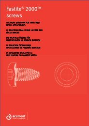
<strong>TAPTITE</strong> <strong>2000</strong> ®<br />
FASTENERS
UNIQUE DESIGN INCREASES PERFORMANCE<br />
<strong>TAPTITE</strong> <strong>2000</strong> ® fasteners are designed to provide<br />
the benefits of previous <strong>TAPTITE</strong> ® fastener<br />
products with an innovative new thread design –<br />
the Radius Profile <strong>Thread</strong>. The proven TRILOBULAR <br />
principle is maintained while incorporating this innovative<br />
thread design. The result is a new generation of <strong>TAPTITE</strong> ®<br />
fasteners, providing excellent mechanical, assembly, and ergonomic<br />
characteristics surpassed by no other technology. <strong>TAPTITE</strong> <strong>2000</strong><br />
fasteners af<strong>for</strong>d end-users with enhanced opportunities to reduce the<br />
overall cost of assembly.<br />
Trilobular Cross Section<br />
FEATURES<br />
• TRILOBULAR configuration reduces<br />
friction<br />
• Radius Profile thread<br />
• Roll <strong>for</strong>ms own work-hardened<br />
mating threads<br />
• Excellent axial alignment<br />
• Variety of point styles available<br />
BENEFITS<br />
The Radius Profile <strong>Thread</strong> design<br />
advances the proven per<strong>for</strong>mance<br />
of Taptite fasteners to<br />
a new level.<br />
• Eases assembly<br />
• Provides superior resistance to<br />
vibration loosening<br />
• Increases drive-to-strip ratio<br />
• Increases prevailing torque<br />
• Provides excellent torque-tension<br />
relationship<br />
• Lowers required drive torque<br />
• Lowers end load requirements<br />
2
B UILT O N P ROVEN P ERFORMANCE<br />
<strong>TAPTITE</strong> ® fasteners have been used in a variety of industries since its<br />
inception over <strong>for</strong>ty years ago. Built upon those years of experience<br />
with the proven per<strong>for</strong>mance features of <strong>TAPTITE</strong> ® , <strong>TAPTITE</strong> ® II, and<br />
Duo-<strong>TAPTITE</strong> ® fasteners, the <strong>TAPTITE</strong> <strong>2000</strong> ® design combines all these<br />
previous benefits with an even lower thread-<strong>for</strong>ming torque. The result<br />
is optimal joint per<strong>for</strong>mance in a wide range of applications.<br />
APPLICATION COMPARISON<br />
<strong>TAPTITE</strong> ® II <strong>Fasteners</strong> Duo-<strong>TAPTITE</strong> ® <strong>Fasteners</strong> <strong>TAPTITE</strong> <strong>2000</strong> ® <strong>Fasteners</strong><br />
Lowest thread-<strong>for</strong>ming torque<br />
x<br />
Positioning applications x x<br />
Structural applications x x<br />
High torque-tension applications x x<br />
High strip-out requirement x x<br />
Automation capability x x<br />
Nut member greater than 1.5 x screw dia. x x<br />
Nut member less than 0.3 x screw dia. x x<br />
Adaptability to different point styles x x<br />
High axial alignment required x x<br />
TRILOBULAR <strong>TAPTITE</strong> <strong>2000</strong> ® FASTENERS VS. OTHER THREAD-ROLLING FASTENERS<br />
Prevailing Torque<br />
Higher Drive-to-Fail Ratio<br />
Lower Starting End Load<br />
<strong>TAPTITE</strong> <strong>2000</strong> ®<br />
<strong>Thread</strong>-rolling<br />
Bolt<br />
IFI 524<br />
Spec.<br />
<strong>TAPTITE</strong> <strong>2000</strong> ®<br />
<strong>Thread</strong>-rolling<br />
Bolt<br />
Round-bodied<br />
<strong>Thread</strong>-rolling<br />
Bolt<br />
<strong>TAPTITE</strong> <strong>2000</strong> ®<br />
<strong>Thread</strong>-rolling<br />
Bolt<br />
Round-bodied<br />
<strong>Thread</strong>-rolling<br />
Bolt<br />
The TRILOBULAR shape of<br />
<strong>TAPTITE</strong> <strong>2000</strong> ® provides high prevailing<br />
torque. Graph shows comparison of a<br />
<strong>TAPTITE</strong> <strong>2000</strong> ® fastener with IFI-524<br />
locking screw specification.<br />
The higher, more uni<strong>for</strong>m<br />
drive-to-fail ratio of <strong>TAPTITE</strong> <strong>2000</strong> ® bolts<br />
provide a built-in safety factor<br />
against over-torquing.<br />
<strong>TAPTITE</strong> <strong>2000</strong> ® fasteners require a low<br />
axial end load to initiate thread<br />
<strong>for</strong>ming.<br />
NOTE: End load and drive-to-fail ratio graphs shown are based on average results recorded when testing an M8 x 1.25 size in unthreaded steel weld<br />
nuts having a 7.45mm diameter hole. Prevailing torque test per IFI-524.<br />
3
D E S I G N S P E C I F I C A T I O N S<br />
Acument Global Technologies has manufactured <strong>TAPTITE</strong> ® fasteners since<br />
1960. Let us put our threaded fastener manufacturing expertise to work <strong>for</strong><br />
you.<br />
DESIGN SPECIFICATIONS FOR <strong>TAPTITE</strong> <strong>2000</strong> ® FASTENERS<br />
Diameters: M1.6 – M16 (#2 – 5/8")<br />
Head Styles: Pan, hex washer, flat, oval, round washer, button head,<br />
fillister and specials<br />
Drive Systems: Any drive system, including the TORX PLUS ® Drive<br />
System<br />
Point Styles: Standard <strong>TAPTITE</strong> ® point, CA point, or “SP” point<br />
Specials: Shoulder screws, double-end studs, collar studs, sems;<br />
others may be available<br />
Materials: Low carbon steel, medium carbon steel, alloy steel, stainless<br />
steel; others may be available<br />
Heat Treat: Camcore ® fasteners or case hardening (see details below)<br />
Please contact an Acument Global Technologies applications<br />
engineer <strong>for</strong> in<strong>for</strong>mation on specials and assistance in selecting the<br />
optimal fastener <strong>for</strong> your application.<br />
Camcore® <strong>Fasteners</strong><br />
<strong>TAPTITE</strong> <strong>2000</strong> ® HEAT TREATMENT<br />
Camcore ® <strong>Fasteners</strong>: When tapping into high strength steel or in<br />
structural applications, a Camcore ® fastener is recommended. Camcore ®<br />
fasteners are made from high strength alloy steel which is through hardened<br />
to HRC 33-39 and tempered. The fastener lead threads are induction<br />
hardened to a minimum of HRC 45 by a secondary induction treatment.<br />
When combined with non-electroplated finishes, resistance to stress<br />
corrosion cracking is improved.<br />
Case Hardening: Case hardening is the standard heat treatment <strong>for</strong> all<br />
<strong>TAPTITE</strong> <strong>2000</strong> ® screws in sizes M5 (#12) and smaller. This process raises<br />
the surface hardness to a level higher than the core hardness.<br />
Through Hardening: Through hardening, which increases toughness<br />
and ductility, is the preferred treatment <strong>for</strong> <strong>TAPTITE</strong> <strong>2000</strong> ® fasteners<br />
used in aluminum applications.<br />
TORX PLUS ® DRIVE SYSTEM<br />
<strong>TAPTITE</strong> <strong>2000</strong> ® fastener per<strong>for</strong>mance is improved with the TORX PLUS ®<br />
Drive System. Its 0° angle provides a more efficient transfer of torque,<br />
improving driveability. Its reduced drive tool tolerance and broad<br />
engagement area increases tool bit fatigue life, so drive tools last longer.<br />
Many styles are available, including internal, external, low-profile external,<br />
tamper-resistant, and dual drives. The AUTOSERT ® feature, which allows<br />
<strong>for</strong> high RPM engagement in internal drives, can be included.<br />
For more in<strong>for</strong>mation on how the TORX PLUS ® Drive System outper<strong>for</strong>ms<br />
other drive systems, go to www.acument.com.
<strong>TAPTITE</strong> <strong>2000</strong> ®<br />
STANDARD FASTENERS<br />
<strong>TAPTITE</strong> <strong>2000</strong> ® STANDARD POINT FASTENERS<br />
<strong>TAPTITE</strong> <strong>2000</strong> ® fasteners have a<br />
special point design featuring a<br />
long lead (3 – 5 threads) <strong>for</strong> low<br />
thread-<strong>for</strong>ming torque. Larger<br />
sizes, M6 (1/4") and larger, have<br />
stabilizing threads to aid<br />
alignment and ease starting.<br />
For M5 (#12) and Smaller<br />
For M6 (1/4") and Larger<br />
LENGTH TOLERANCE<br />
Metric per ANSI B18.6.7M<br />
Nominal Screw Length<br />
to 3mm inclusive<br />
over 3 to 10mm inclusive<br />
over 10 to 16mm inclusive<br />
over 16 to 50mm inclusive<br />
over 50mm<br />
Inch per ANSI B18.6.3<br />
Tolerance<br />
on Length<br />
±0.2mm<br />
±0.3mm<br />
±0.4mm<br />
±0.5mm<br />
±1.0mm<br />
Nominal Screw Size<br />
Nominal #4 – #12 1/4" – 1/2"<br />
Screw Length Tolerance on Length<br />
To 1/2" inclusive +0, – .020" +0, – .030"<br />
Over 1/2" to 1"<br />
inclusive<br />
+0, – .030" +0, – .030"<br />
Over 1" to 2"<br />
inclusive<br />
+0, – .060" +0, – .060"<br />
Over 2" +0, – .090" +0, – .090"<br />
DIMENSIONAL DATA – METRIC SIZES (mm)<br />
Screw Body Dimensions<br />
Point<br />
Screw C D Cp<br />
Size Nominal Nominal Max.<br />
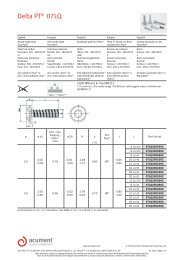
M1.6 x 0.35 1.60 1.56 1.40<br />
M2.0 x 0.40 2.00 1.96 1.77<br />
M2.5 x 0.45 2.50 2.45 2.25<br />
M3 x 0.5 3.00 2.95 2.71<br />
M3.5 x 0.6 3.50 3.44 3.17<br />
M4 x 0.7 4.00 3.93 3.60<br />
M5 x 0.8 5.00 4.92 4.55<br />
M6 x 1.0 6.00 5.90 5.38<br />
M8 x 1.25 8.00 7.87 7.23<br />
M10 x 1.5 10.00 9.85 9.08<br />
M12 x 1.75 12.00 11.82 10.92<br />
M14 x 2.0 14.00 13.80 12.77<br />
M16 x 2.0 16.00 15.80 14.76<br />
DIMENSIONAL DATA – INCH SIZES (in)<br />
Screw Body Dimensions<br />
Point<br />
Screw C D Cp<br />
Size Nominal Nominal Max.<br />
2-56 0.086 0.084 0.077<br />
3-48 0.099 0.097 0.088<br />
4-40 0.112 0.110 0.098<br />
5-40 0.125 0.123 0.111<br />
6-32 0.138 0.135 0.121<br />
8-32 0.164 0.161 0.147<br />
10-24 0.190 0.186 0.167<br />
10-32 0.190 0.187 0.174<br />
12-24 0.216 0.212 0.193<br />
1/4-20 0.250 0.245 0.220<br />
5/16-18 0.313 0.307 0.279<br />
3/8-16 0.375 0.369 0.337<br />
7/16-14 0.438 0.431 0.394<br />
7/16-20 0.438 0.433 0.407<br />
1/2-13 0.500 0.492 0.453<br />
9/16-12 0.563 0.555 0.511<br />
5/8-11 0.625 0.616 0.569<br />
5
<strong>TAPTITE</strong> <strong>2000</strong> ®<br />
STANDARD FASTENERS<br />
RECOMMENDED PILOT HOLE SIZES IN STEEL NUT MEMBERS – METRIC SIZES (mm)<br />
Application Light Medium-Light Medium-Heavy Full Strength Extended<br />
Duty Class 0.3 Diameters of Material 0.5 Diameters of Material 0.75 Diameters of Material 1.0 Diameters of Material 1.25 Diameters of Material<br />
Percentage<br />
of <strong>Thread</strong><br />
90% 80% 70% 65% 60%<br />
Nominal Material Pilot Drill Material Pilot Drill Material Pilot Drill Material Pilot Drill Material Pilot Drill<br />
Size Thckns. Hole Size Thckns. Hole Size Thckns. Hole Size Thckns. Hole Size Thckns. Hole Size<br />
M2.5 x 0.45 0.5 - 0.9 2.24 2.25 0.9 - 1.5 2.27<br />
#43<br />
2.26<br />
1.5 - 2.1 2.3 2.3 2.1 - 2.7 2.31 2.3 2.7 - 3.5 2.32 2.3<br />
M3 x 0.5 0.5 - 1.1 2.71<br />
#36<br />
7/64<br />
7/64<br />
1.1 - 1.7 2.74 2.75 1.7 - 2.7 2.77<br />
2.7 - 3.3 2.79<br />
2.71 2.78 2.78<br />
3.3 - 4.0 2.8 2.8<br />
M3.5 x 0.6 0.6 - 1.4 3.15<br />
1/8<br />
#30<br />
1.4 - 2.0 3.19 3.2 2.0 - 2.9 3.23 3.25 2.9 - 3.8 3.25 3.25 3.8 - 4.5 3.27<br />
3.18 3.27<br />
M4 x 0.7 0.8 - 1.4 3.59 3.6 1.4 - 2.4 3.64<br />
#27<br />
#26<br />
2.4 - 3.3 3.68 3.7 3.3 - 4.4 3.7 3.7 4.4 - 5.5 3.73<br />
3.66 3.73<br />
M4.5 x 0.75 0.9 - 1.7 4.06<br />
#21<br />
4.04<br />
1.7 - 2.7 4.11 4.1 2.7 - 3.9 4.16 4.2 3.9 - 4.9 4.18 4.2 4.9 - 6.4 4.21 4.2<br />
M5 x 0.8 1.0 - 2.1 4.53 4.5 2.1 - 2.9 4.58 4.57 2.9 - 4.4 4.64<br />
#14<br />
4.62<br />
4.4 - 5.9 4.66 4.65 5.9 - 7.1 4.69 4.7<br />
M6 x 1.0 1.2 - 2.4 5.42<br />
#3<br />
7/32<br />
2.4 - 3.6 5.48 5.5 3.6 - 4.9 5.55<br />
5.41 5.56<br />
4.9 - 6.9 5.58 5.6 6.9 - 8.1 5.61 5.6<br />
M7 x 1.0 1.4 - 2.4 6.42 6.4 2.4 - 4.4 6.48 6.5 4.4 - 6.5 6.55<br />
F<br />
6.53<br />
6.5 - 7.7 6.58 6.6 7.7 - 9.5 6.61 6.6<br />
M8 x 1.25 1.6 - 3.1 7.27 7.25 3.1 - 4.9 7.35<br />
L<br />
M<br />
4.6 - 6.9 7.43 7.4 6.9 - 8.9 7.47<br />
7.37 7.49<br />
8.9 - 10.9 7.51 7.5<br />
M10 x 1.5 1.9 - 3.9 9.12<br />
23/64<br />
U<br />
3.9 - 5.9 9.22 9.25 5.9 - 8.3 9.32 9.3 8.3 - 10.9 9.37<br />
9.1 9.35<br />
10.9 - 12.9 9.41 9.4<br />
M12 x 1.75 2.4 - 4.9 10.98 11.0 4.9 - 7.4 11.09<br />
7/16<br />
7/16<br />
7.4 - 10.5 11.2<br />
11.11 11.11<br />
10.5 - 14.5 11.26 11.3 14.5 - 17.0 11.31 11.3<br />
RECOMMENDED PILOT HOLE SIZES IN STEEL NUT MEMBERS – INCH SIZES (in)<br />
Application Light Medium-Light Medium-Heavy Full Strength Extended<br />
Duty Class 0.3 Diameters of Material 0.5 Diameters of Material 0.75 Diameters of Material 1.0 Diameters of Material 1.25 Diameters of Material<br />
Percentage<br />
of <strong>Thread</strong><br />
90% 80% 70% 65% 60%<br />
Nominal Material Pilot Drill Material Pilot Drill Material Pilot Drill Material Pilot Drill Material Pilot Drill<br />
Size Thckns. Hole Size Thckns. Hole Size Thckns. Hole Size Thckns. Hole Size Thckns. Hole Size<br />
2-56 .017-.034 0.0756 1.9mm . 034-.052 0.0767 1.95mm 5/64 #47<br />
2mm<br />
.052-.073 0.0779 .073-.095 0.0785 .095-.169 0.0790<br />
0.0748 0.0763 0.0781 0.0785 0.0787<br />
3-48 020-.040 0.8680 2.2mm #43<br />
#43<br />
.040-.059 0.0882<br />
.059-.084 0.0895 .084-.110 0.0902 2.3mm .110-.141 0.0909 2.3mm<br />
0.0866 0.089 0.089 0.0906 0.0906<br />
4-40 .022-.045 0.0974<br />
#40<br />
#39<br />
#39<br />
#38<br />
.045-.067 0.0990<br />
.067-.095 0.1006 .095-.126 0.1014 .126-.157 0.1023 2.6mm<br />
0.098 0.0995 0.0995 0.1015 0.0906<br />
5-40 .025-.051 0.1104 2.8mm #33<br />
#33<br />
.051-.075 0.1120<br />
.075-.106 0.1136 .106-.141 0.1144 2.9mm .141-.175 0.1153 2.9mm<br />
0.1102 0.113 0.113 0.1142 0.1142<br />
6-32 .028-.066 0.1197<br />
#31<br />
.066-.083 0.1218 3.1mm 1/8<br />
1/8<br />
.083-.117 0.1238 .117-.152 0.1248 .152-.193 0.1258 3.2mm<br />
0.120 0.122 0.125 0.125 0.126<br />
8-32 .033-.066 0.1457 3.7mm .066-.098 0.1478 3.75mm .098-.141 0.1498 3.8mm .141-1.80 0.1508 3.8mm #24<br />
.180-.230 0.1518<br />
0.1457 0.1476 0.1496 0.1491 0.152<br />
10-24 .038-.079 0.1656<br />
#19<br />
#18<br />
.079-.114 0.1683<br />
.114-.162 0.1710 11/64 11/64 4.4mm<br />
.162-.209 0.1724 .209-.266 0.1738<br />
0.166 0.1695 0.1719 0.1719 0.1732<br />
10-32 .038-.079 0.1717 11/64 #17<br />
#16<br />
#16<br />
.079-.114 0.1738<br />
.114-.162 .01758 .162-.209 0.1768 .209-.266 0.1778 4.5mm<br />
0.1719 0.173 0.177 0.177 0.1772<br />
12-24 .043-.086 0.1916<br />
#11<br />
#9<br />
5mm #8<br />
.086-.130 0.1943<br />
.130-.184 0.1970 .184-.238 0.1984 .238-.302 0.1998 5.1mm<br />
0.191 0.196 0.1969 0.199 0.2008<br />
1/4-20 .050-.100 0.2208<br />
#2<br />
.100-.150 0.2240 5.7mm #1<br />
.150-.213 0.2273 .213-.275 0.2289 5.8mm .275-.350 0.2309 5.8mm<br />
0.221 0.2244 0.228 0.2283 0.2283<br />
5/16-18 .062-.126 0.2800 7.1mm .126-.188 0.2836 7.2mm .188-.266 0.2872 7.3mm L<br />
.266-.345 0.2890 .345-.438 0.2908 7.4mm<br />
0.2795 0.2835 0.2874 0.29 0.2913<br />
3/8-16 .075-.150 0.3384 8.6mm .150-.225 0.3425 8.7mm .225-.319 0.3466 8.8mm Size<br />
.319-.413 0.3486 .413-.525 0.3506 8.9mm<br />
0.3386 0.3425 0.3465 0.348 0.3504<br />
7/16-14 .087-.174 0.3957<br />
X<br />
X<br />
Y<br />
13/32 13/32<br />
.174-.262 0.4004<br />
.262-.371 .04050 .371-.481 0.4073 .481-.612 0.4096<br />
0.397 0.397 0.404 0.4063 0.4063<br />
1/2-13 .100-.200 0.4550 29/64 29/64 15/32 15/32 15/32<br />
.200-.300 0.4600<br />
.300-.425 0.4650 .425-.550 0.4675 .550-.700 0.4700<br />
0.4531 0.4531 0.4688 0.4688 0.468<br />
6<br />
APPLICATION DUTY CLASS - A general term used here to group material thickness in terms of screw diameters. For example, the average<br />
material thickness listed under ”medium-heavy” equals 75% of the screw diameter.
<strong>TAPTITE</strong> <strong>2000</strong> ®<br />
STANDARD FASTENERS<br />
RECOMMENDED EXTRUDED PILOT HOLE SIZES IN LIGHT-GAGE STEEL<br />
Extruding holes <strong>for</strong> fasteners in lightgage<br />
steel nearly doubles the length of<br />
thread engagement over the original<br />
material thickness.<br />
HOLE SIZE DIAMETER (D) PER MATERIAL THICKNESS – METRIC SIZES (mm)<br />
MATERIAL THICKNESS<br />
SCREW SIZE 0.50 – 0.69 0.70 – 0.99 1.00 – 1.49 1.50 – 2.49 2.50 – 3.00<br />
M2.5 x 0.45 2.22 2.23 2.24 — —<br />
M3 x 0.5 2.70 2.71 2.72 — —<br />
M4 x 0.7 3.57 3.59 3.61 3.64 —<br />
M5 x 0.8 — 4.53 4.56 4.59 —<br />
M6 x 1.0 — 5.42 5.45 5.48 5.51<br />
M8 x 1.25 — — 7.27 7.31 7.35<br />
EXTRUDED HOLE THICKNESSES – METRIC SIZES (mm)<br />
APPROXIMATE MATERIAL THICKNESS “T”<br />
METRIC 0.6 – 1.0 1.0 – 1.2 1.2 – 2.0 2.0 – 2.5 2.5 – 3.0<br />
HOLE DIA. D H R H R H R H R H R<br />
2.00 – 2.55 1.00 0.13 1.00 0.13 1.00 0.15 1.10 0.25 — —<br />
2.56 – 3.20 1.20 0.13 1.20 0.13 1.20 0.15 1.30 0.25 1.35 0.25<br />
3.21 – 3.80 1.35 0.13 1.35 0.13 1.35 0.15 1.50 0.25 1.60 0.25<br />
3.81 – 4.60 — — 1.50 0.13 1.55 0.15 1.80 0.25 1.90 0.25<br />
4.61 – 5.60 — — 1.80 0.13 1.80 0.15 2.30 0.25 2.40 0.25<br />
5.61 – 6.60 — — — — 1.90 0.15 2.55 0.25 2.65 0.25<br />
6.61 – 7.60 — — — — 2.10 0.15 2.95 0.25 3.20 0.25<br />
<strong>TAPTITE</strong> <strong>2000</strong> ® fasteners develop<br />
almost twice the failure torque in<br />
extruded holes, providing maximum<br />
joint integrity.<br />
Example: The chart shows that <strong>for</strong> a<br />
M4 x 0.7 screw in a material<br />
thickness of 0.75mm the suggested<br />
hole diameter is 3.59mm. The<br />
corresponding “H” dimension is the<br />
1.35mm minimum, making the total<br />
length of engagement 2.1mm<br />
minimum.<br />
HOLE SIZE DIAMETER (D) PER MATERIAL THICKNESS – INCH SIZES (in)<br />
MATERIAL THICKNESS<br />
SCREW SIZE 020 – .029 .030 – .039 .040 – .059 .060 – .099 .100 – .130<br />
4-40 0.097 0.097 0.098 — —<br />
6-32 0.119 0.120 0.121 0.122 —<br />
8-32 0.145 0.146 0.147 0.148 —<br />
10-24 0.164 0.166 0.168 0.170 0.170<br />
10-32 0.171 0.172 0.173 0.174 0.174<br />
1/4-20 — 0.221 0.223 0.225 0.225<br />
5/16-18 — — 0.282 0.285 0.285<br />
EXTRUDED HOLE THICKNESSES – INCH SIZES (in)<br />
APPROXIMATE MATERIAL THICKNESS “T”<br />
HOLE 0.020 – 0.035 0.035 – 0.050 0.050 – 0.075 0.075 – 0.100 0.100 – 0.125<br />
DIA. (D) H R H R H R H R H R<br />
.081 – .100 0.040 0.005 0.040 0.005 0.040 0.006 0.043 0.010 — —<br />
.101 – .125 0.047 0.005 0.047 0.005 0.047 0.006 0.052 0.010 0.054 0.010<br />
.126 – .150 0.053 0.005 0.053 0.005 0.053 0.006 0.060 0.010 0.063 0.010<br />
.151 – .180 — — 0.060 0.005 0.060 0.006 0.070 0.010 0.075 0.010<br />
.181 – .220 — — 0.070 0.005 0.070 0.006 0.090 0.010 0.095 0.010<br />
.221 – .260 — — — — 0.075 0.006 0.100 0.010 0.105 0.010<br />
.261 – .300 — — — — 0.083 0.006 0.116 0.010 0.125 0.010<br />
7
<strong>TAPTITE</strong> <strong>2000</strong> ® STANDARD FASTENERS<br />
HOLE SIZES PER PERCENTAGE OF THREAD ENGAGEMENT – METRIC SIZES (mm)<br />
Nominal<br />
Percent <strong>Thread</strong> Engagement<br />
Screw Size 100 95 90(1) 85(1) 80 75 70 65 60 55 50 45 40 35<br />
M2.5 x 0.45 2.21 2.22 2.24 2.25 2.27 2.28 2.29 2.31 2.32 2.34 2.35 2.37 2.38 2.40<br />
M3 x 0.5 2.67 2.69 2.71 2.72 2.74 2.76 2.77 2.79 2.80 2.82 2.84 2.85 2.87 2.90<br />
M3.5 x 0.6 3.11 3.13 3.15 3.17 3.19 3.21 3.23 3.25 3.27 3.29 3.30 3.32 3.34 3.36<br />
M4 x 0.7 3.54 3.57 3.59 3.61 3.64 3.66 3.68 3.70 3.73 3.75 3.77 3.79 3.80 3.84<br />
M4.5 x 0.75 4.01 4.04 4.06 4.09 4.11 4.13 4.16 4.18 4.21 4.23 4.26 4.28 4.30 4.33<br />
M5 x 0.8 4.48 4.51 4.53 4.56 4.58 4.61 4.64 4.66 4.69 4.71 4.74 4.77 4.79 4.82<br />
M6 x 1.0 5.35 5.38 5.42 5.45 5.48 5.51 5.54 5.58 5.61 5.64 5.67 5.71 5.74 5.77<br />
M7 x 1.0 6.35 6.38 6.42 6.45 6.48 6.51 6.54 6.58 6.61 6.64 6.67 6.71 6.74 6.77<br />
M8 x 1.25 7.19 7.23 7.27 7.31 7.35 7.39 7.43 7.47 7.51 7.55 7.59 7.63 7.67 7.72<br />
M10 x 1.5 9.03 9.07 9.12 9.17 9.22 9.27 9.32 9.37 9.41 9.46 9.51 9.56 9.61 9.66<br />
M12 x 1.75 10.86 10.92 10.98 11.30 11.09 11.15 11.20 11.26 11.31 11.37 11.43 11.49 11.55 11.60<br />
HOLE SIZES PER PERCENTAGE OF THREAD ENGAGEMENT – INCH SIZES (in)<br />
Nominal Percent <strong>Thread</strong> Engagement<br />
Screw<br />
Size<br />
100 95 90(1) 85(1) 80 75 70 65 60 55 50 45 40 35<br />
2-56<br />
0.074 0.075 0.075 0.076 0.076 0.077 0.077 0.078 0.079 0.079 0.080 0.080 0.081 0.081<br />
4 0 6 1 7 3 9 5 0 6 2 8 4 9<br />
3-48<br />
0.085 0.086 0.086 0.087 0.088 0.088 0.089 0.090 0.090 0.091 0.092 0.092 0.093 0.094<br />
5 1 8 5 2 8 5 2 9 6 2 9 6 3<br />
4-40<br />
0.095 0.096 0.097 0.098 0.099 0.099 0.100 0.101 0.102 0.103 0.103 0.104 0.105 0.106<br />
8 6 4 2 0 8 6 4 3 1 9 7 5 3<br />
5-40<br />
0.108 0.109 0.110 0.111 0.112 0.112 0.113 0.114 0.115 0.116 0.116 0.117 0.118 0.119<br />
8 6 4 2 0 8 6 4 3 1 9 7 5 3<br />
6-32<br />
0.117 0.118 0.119 0.120 0.121 0.122 0.123 0.124 0.125 0.126 0.127 0.128 0.129 0.130<br />
7 7 7 7 8 8 8 8 8 8 8 9 9 9<br />
8-32<br />
0.143 0.144 0.145 0.146 0.147 0.148 0.149 0.150 0.151 0.152 0.153 0.154 0.155 0.156<br />
7 7 7 7 8 8 8 8 8 8 8 9 9 9<br />
10-24<br />
0.162 0.164 0.165 0.167 0.168 0.169 0.171 0.172 0.173 0.175 0.176 0.177 0.179 0.180<br />
9 3 6 0 3 7 0 4 8 1 5 8 2 5<br />
10-32<br />
0.169 0.170 0.171 0.172 0.173 0.174 0.175 0.176 0.177 0.178 0.179 0.180 0.181 0.182<br />
7 7 7 7 8 8 8 8 8 8 8 9 9 9<br />
12-24<br />
0.188 0.190 0.191 0.193 0.194 0.195 0.197 0.198 0.199 0.201 0.202 0.203 0.205 0.206<br />
9 3 6 0 3 7 0 4 8 1 5 8 2 5<br />
1/4-20<br />
0.217 0.219 0.220 0.222 0.224 0.225 0.227 0.228 0.230 0.232 0.233 0.235 0.237 0.238<br />
5 1 8 4 0 6 3 9 5 1 8 4 0 6<br />
5/16-18<br />
0.276 0.278 0.280 0.281 0.283 0.285 0.287 0.289 0.290 0.292 0.294 0.296 0.298 0.299<br />
4 2 0 8 6 4 2 0 8 6 4 3 1 9<br />
3/8-16<br />
0.334 0.336 0.338 0.340 0.342 0.344 0.346 0.348 0.350 0.352 0.354 0.356 0.358 0.360<br />
NOTE: Nominal screw diameters are used when calculating hole sizes and are based on the U.S. basic<br />
thread depth of .6495 times the pitch. Hole data accuracy decreases <strong>for</strong> engagements less than 70%. This is<br />
because the above data is based on a linear relation between hole size and percentage of thread<br />
engagement.<br />
Hole Size = D – (0.6495 x P x %). In this equation, D is equal to the nominal screw diameter.<br />
(1)<br />
Pilot holes listed under the 90% and 85% thread engagement columns are recommended <strong>for</strong> single punch<br />
extruded holes.<br />
Typical tolerance <strong>for</strong> the pilot hole range is -10% to +5% from the nominal percent thread engagement. Example: <strong>for</strong><br />
a M12 <strong>TAPTITE</strong> <strong>2000</strong> ® fastener using a single punch extruded hole, the nominal hole size is 85% thread<br />
engagement or 11.30mm, bounded by a tolerance window of 11.15mm (75% thread engagement) to 10.98mm<br />
(90% thread engagement.<br />
PROPER DESIGN<br />
Due to the variability of materials such as cast iron and powdered metals, please contact an Acument Global<br />
Technologies applications engineer <strong>for</strong> proper hole size recommendations to ensure proper fastener per<strong>for</strong>mance.
S P E C I A L P O I N T D E S I G N S<br />
<strong>TAPTITE</strong> <strong>2000</strong> ® CA POINT FASTENERS<br />
<strong>TAPTITE</strong> <strong>2000</strong> ® CA fasteners have a gimlet<br />
point <strong>for</strong> use where clearance holes and pilot<br />
holes do not align. The CA point is also good<br />
<strong>for</strong> rapid hole finding, floating nut members<br />
or difficult access applications.<br />
The CA point can be supplied with a sharp point or a slightly<br />
truncated blunt point, which is desirable <strong>for</strong> situtations when the<br />
sharp point could be a potential hazard to wires, components or<br />
assembly line and service personnel.<br />
<strong>TAPTITE</strong> <strong>2000</strong> ® “SP” (SHORT POINT) FASTENERS<br />
<strong>TAPTITE</strong> <strong>2000</strong> ® “SP” fasteners have a shorter<br />
point than standard <strong>TAPTITE</strong> <strong>2000</strong> ® fasteners<br />
to maximize full thread engagement in blind<br />
holes, particularly in non-ferrous materials,<br />
such as aluminum.<br />
The short point of the <strong>TAPTITE</strong> <strong>2000</strong> ® “SP” <br />
fastener maximizes the amount of full thread<br />
engagment in blind holes. Increasing the full<br />
thread engagment is often critical in shallow<br />
depth holes. In many cases the failure mode<br />
can can be shifted from internal thread<br />
stripping to fastener fracture, which is<br />
typically desired in castings. In deeper holes,<br />
the shorter “SP” point may allow use of a<br />
shorter fastener, saving weight and cost.<br />
9
<strong>TAPTITE</strong> <strong>2000</strong> ® SP F ASTENERS<br />
RECOMMENDED PILOT HOLE SIZES FOR ALUMINUM OR ZINC ALLOY DIE CASTINGS FOR <strong>TAPTITE</strong> <strong>2000</strong> SP FASTENERS<br />
METRIC SIZES (mm)<br />
Distance to<br />
F L H Edge <strong>for</strong> No<br />
Hole Diameter as Cast Hole Dia Length Boss Measurable<br />
Screw Top A Bottom B as of <strong>Thread</strong> Dia. Distortion<br />
Size Max. Min. Max. Min. Drilled Engagement Min. Min.<br />
M2 x 0.40 1.91 1.83 1.81 1.73 1.82 4.00 3.32 1.0<br />
M2.5 x 0.45 2.39 2.31 2.28 2.20 2.29 5.00 4.15 1.2<br />
M3 x 0.5 2.90 2.82 2.76 2.68 2.77 6.00 4.98 1.3<br />
M3.5 x 0.6 3.31 3.23 3.21 3.13 3.23 7.00 5.81 1.6<br />
M4 x 0.7 3.82 3.74 3.64 3.56 3.68 8.00 6.64 1.8<br />
M5 x 0.8 4.80 4.72 4.58 4.50 4.64 10.00 8.30 2.1<br />
M6 x 1.0 5.74 5.66 5.48 5.40 5.54 12.00 9.96 2.6<br />
M7 x 1.0 6.78 6.70 6.48 6.40 6.54 14.00 11.62 2.6<br />
M8 x 1.25 7.69 7.61 7.35 7.27 7.43 16.00 13.28 3.3<br />
M10 x 1.5 9.64 9.56 9.22 9.14 9.32 20.00 16.60 3.9<br />
M12 x 1.75 11.59 11.51 11.09 11.01 11.20 24.00 19.92 4.6<br />
INCH SIZES (in)<br />
Distance to<br />
F L H Edge <strong>for</strong> No<br />
Hole Diameter as Cast Hole Dia Length Boss Measurable<br />
Screw Top A Bottom B as of <strong>Thread</strong> Dia. Distortion<br />
Size Max. Min. Max. Min. Drilled Engagement Min. Min.<br />
2-56 0.081 0.078 0.077 0.074 0.0779 0.172 0.197 0.046<br />
3-48 0.093 0.090 0.088 0.085 0.0895 0.198 0.208 0.054<br />
4-40 0.105 0.102 0.099 0.096 0.1006 0.224 0.220 0.065<br />
5-40 0.118 0.115 0.112 0.109 0.1136 0.250 0.232 0.065<br />
6-32 0.128 0.125 0.122 0.119 0.1238 0.276 0.242 0.081<br />
8-32 0.155 0.152 0.148 0.145 0.1498 0.328 0.272 0.081<br />
10-24 0.177 0.174 0.168 0.165 0.1710 0.380 0.315 0.108<br />
10-32 0.182 0.179 0.174 0.171 0.1758 0.380 0.315 0.081<br />
12-24 0.203 0.200 0.194 0.191 0.1970 0.432 0.359 0.108<br />
1/4-20 0.235 0.232 0.224 0.221 0.2273 0.500 0.415 0.130<br />
5/16-18 0.297 0.294 0.284 0.281 0.2872 0.625 0.519 0.144<br />
3/8-16 0.359 0.356 0.343 0.340 0.3466 0.750 0.623 0.162<br />
7/16-14 0.419 0.416 0.400 0.397 0.4050 0.875 0.726 0.186<br />
1/2-13 0.481 0.478 0.460 0.457 0.4650 1.000 0.830 0.200<br />
The minimum length of thread engagement should be equal to twice<br />
the diameter of the screw (to approach utilizing available screw<br />
strength). To ensure optimum per<strong>for</strong>mance, the hole diameter should<br />
provide <strong>for</strong> 65% to 75% thread engagement.<br />
10
L O W E R I N -P L A C E C O S T S<br />
Through the elimination of tapping operations and their optimal per<strong>for</strong>mance, <strong>TAPTITE</strong> <strong>2000</strong> ® fasteners can lower your installed<br />
costs. Have you considered these design and assembly issues that <strong>TAPTITE</strong> <strong>2000</strong> ® fasteners can eliminate or improve?<br />
SAVINGS THROUGH ELIMINATION OF<br />
TAPPING OPERATIONS<br />
Total savings from elimination of tapping<br />
operations<br />
SAVINGS THROUGH INCREASED PERFORMANCE OF<br />
<strong>TAPTITE</strong> <strong>2000</strong> ® FASTENERS<br />
Advantage Est. Cost Savings Advantage Est. Cost Savings<br />
Direct labor <strong>for</strong> tapping operations $<br />
Indirect labor <strong>for</strong> tapping operations<br />
Taps<br />
Jogs and fixtures<br />
Tapping lubricants<br />
Gauges<br />
Set-up time of tapping equipment<br />
Downtime on automated equipment due to<br />
tapping station malfunction<br />
Downtime to replace broken taps<br />
Low machine efficiency from loading, galling<br />
and binding of taps<br />
Cleaning of oil and chips<br />
Inspection <strong>for</strong> class of fit<br />
Loss or repair of tapped assemblies due to<br />
under- or over-sized tapped threads<br />
Loss or repair of tapped assemblies due to<br />
tap breakage<br />
Moving components to and from tapping<br />
department<br />
Use of drilling and tapping stations <strong>for</strong> other<br />
needed operations<br />
Improved cycle time on multi-operation<br />
equipment<br />
Elimination of cross-threading into<br />
pre-tapped holes<br />
Elimination of tapped holes clogged with<br />
paint or other <strong>for</strong>eign materials<br />
Reduction of drilling operations – holes can<br />
be cored or punched during part blanking<br />
Allows largest diameter punch in each screw<br />
size <strong>for</strong> less breakage and longer life<br />
Can thread directly into less expensive<br />
untapped tubular rivets and bushings<br />
Uni<strong>for</strong>m driving torque, low end load<br />
requirements, and high drive-to-fail ratios<br />
Reduced assembly problems from stripped<br />
threads and unseated fasteners<br />
Lowered tool costs from extended driver,<br />
bit and socket life<br />
Reduced operator fatigue<br />
Eliminated use of waxes or lubricants<br />
Superior vibration resistance and excellent<br />
torque-tension relationship<br />
Smaller diameter or fewer screws can be<br />
used<br />
Can replace threaded inserts<br />
Can be used as an adjusting or<br />
calibrating screw<br />
Can be made captive without costly<br />
secondary operations<br />
Elimination of lock nuts, washers and other<br />
secondary locking devices<br />
Reduced need <strong>for</strong> weld and clinch nuts by<br />
utilizing extruded holes<br />
Greater use of die casting and other soft<br />
materials<br />
Improved quality and joint integrity<br />
Short point available<br />
Shorter holes can be used where hole<br />
length is restricted<br />
Total savings from improved per<strong>for</strong>mance<br />
of <strong>TAPTITE</strong> <strong>2000</strong> ® fasteners<br />
OVERALL SAVINGS<br />
Total savings from elimination of<br />
tapping operations<br />
Total savings from improved<br />
per<strong>for</strong>mance of <strong>TAPTITE</strong> <strong>2000</strong> ® fasteners<br />
Total savings<br />
Number of gained advantages<br />
$<br />
$<br />
11
Y O U R S I N G L E S O U R C E<br />
In today’s global economy, effective support from suppliers is more vital than ever. Acument Global<br />
Technologies is poised to be your fully-integrated partner in every stage of the product cycle.<br />
GLOBAL SUPPLY<br />
Acument Global Technologies is the global leader in providing<br />
fastening solutions to manufacturers around the world. With<br />
more than 12,000 employees in over 17 countries, Acument<br />
Global Technologies is able to provide fastening and<br />
assembly solutions on a global scale.<br />
BROAD MANUFACTURING CAPABILITIES<br />
Acument Global Technologies has among the broadest range<br />
of manufacturing capabilities available from the fastener industry.<br />
From threaded fasteners to blind rivets to cold <strong>for</strong>med components,<br />
we are the global leader in fastener manufacturing technology.<br />
ENGINEERED SOLUTIONS<br />
Acument Global Technologies application engineers have the<br />
know-how and equipment to uncover the optimal solution <strong>for</strong> your<br />
application. Design assistance and thorough testing allow you to choose<br />
the optimal fastening technology <strong>for</strong> your unique requirements.<br />
QUALITY PRODUCTS<br />
Acument Global Technologies products are produced to the highest quality standards. Substantial<br />
testing procedures in every production phase ensure a consistently high level of quality to ensure<br />
reliable per<strong>for</strong>mance.<br />
AUTOMATION CAPABILITIES & ASSEMBLY SOLUTIONS<br />
Drawing on its well-established products and application experience, Acument Global Technologies<br />
can configure the optimal tooling system <strong>for</strong> your assembly line. From simple, two-headed modules to<br />
multi-headed equipment, these systems can dramatically reduce assembly time and costs.<br />
SUPPLY CHAIN SOLUTIONS<br />
Global vendor-managed inventory programs, global warehousing and distribution programs, global<br />
supply capabilities, JIT and Kan Ban programs, custom packaging and more are among our complete<br />
range of logistic services. We can design a custom program to meet your global needs.<br />
The in<strong>for</strong>mation in this manual is not to<br />
be considered a specification.<br />
Taptite ® , <strong>TAPTITE</strong> <strong>2000</strong> ® , SP , CA and the Taptite <strong>2000</strong> logo are<br />
trademarks of Research, Engineering & Manufacturing Inc.<br />
(REMINC). TORX ® , TORX PLUS ® , Camcore ® , and AUTOSERT ®<br />
are registered trademarks of Acument Intellectual Properties, LLC.<br />
6125 Eighteen Mile Road<br />
Sterling Heights, Michigan 48314<br />
1-800-544-6117<br />
acument.com<br />
camcarsolutions.com<br />
ringscrew.com<br />
Printed in the U.S.A. ©2002-2007 Acument Intellectual Properties, LLC. REV: 02/01/07