Multibody Contact Simula- tion of Constant Velocity Plunging Joint
Multibody Contact Simula- tion of Constant Velocity Plunging Joint
Multibody Contact Simula- tion of Constant Velocity Plunging Joint

Create successful ePaper yourself
Turn your PDF publications into a flip-book with our unique Google optimized e-Paper software.
98 IMW - Institutsmitteilung Nr. 35 (2010)<br />
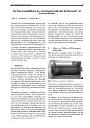
locity joint” in Simpack. The screenshot <strong>of</strong> the whole multibody model<br />
is shown in Fig. 3.<br />
Figure3: Screenshot <strong>of</strong> the multibody model <strong>of</strong> CV plunging joint<br />
3 <strong>Multibody</strong> contact simula<strong>tion</strong> and simula<strong>tion</strong> results<br />
Tab. 1 shows the main dimensions <strong>of</strong> ball plunging CVJ and load<br />
condi<strong>tion</strong>s used in the simula<strong>tion</strong>. The driving torque loaded on the<br />
outer race <strong>of</strong> CV plunging joint and the resisting torque loaded on<br />
the wheel shaft are 1000 N·m and -1000 N·m respectively. The initial<br />
angle velocity <strong>of</strong> the joint is 80 Rad/s.<br />
Ball diameter<br />
d<br />
Effective radius<br />
R<br />
Torque T<br />
<strong>Velocity</strong> ω<br />
22.225 mm 31.95 mm 1000 Nm 80 Rad/s<br />
Table 1: Main dimensions and load condi<strong>tion</strong>s used in the simula<strong>tion</strong><br />
At first, the CV plunging joint is running with fixed articula<strong>tion</strong> angle<br />
10 0 , that’s to say, without plunging. Fig. 4 shows the change <strong>of</strong> contact<br />
forces between balls and races during rota<strong>tion</strong> <strong>of</strong> the joint. The