Multibody Contact Simula- tion of Constant Velocity Plunging Joint
Multibody Contact Simula- tion of Constant Velocity Plunging Joint
Multibody Contact Simula- tion of Constant Velocity Plunging Joint

Create successful ePaper yourself
Turn your PDF publications into a flip-book with our unique Google optimized e-Paper software.
IMW - Institutsmitteilung Nr. 35 (2010) 95<br />
<strong>Multibody</strong> <strong>Contact</strong> <strong>Simula</strong><strong>tion</strong><br />
<strong>of</strong> <strong>Constant</strong> <strong>Velocity</strong><br />
<strong>Plunging</strong> <strong>Joint</strong><br />
Shen, L.J.<br />
<strong>Constant</strong> velocity plunging joint is one <strong>of</strong><br />
the important components in automotive<br />
drivelines, the overall dynamic performances<br />
<strong>of</strong> the constant velocity plunging joint are<br />
not fully reported or described in the past. Intend to obtain more precise<br />
estima<strong>tion</strong> <strong>of</strong> the dynamic contact forces between balls and races and<br />
the movements <strong>of</strong> the balls in races, this paper apply polygon contact<br />
model to simulate the contact dynamics <strong>of</strong> constant velocity plunging<br />
joint with SIMPACK s<strong>of</strong>tware package.<br />
1 Introduc<strong>tion</strong><br />
The annual produc<strong>tion</strong> <strong>of</strong> constant velocity joint (CVJ) for use in driveshaft<br />
currently totals more than 2 billion and CVJ remains a highly<br />
pr<strong>of</strong>itable business in the near future. With growing demands to improving<br />
fuel economy, performance, durability and drivability <strong>of</strong> vehicles,<br />
demands for CVJ to be made smaller and more lightweight,<br />
more durable, and better NVH performance are increasing rapidly /1/.<br />
Among all kinds <strong>of</strong> CVJ, CV plunging joints are <strong>of</strong>ten used as inboard<br />
joints in side shafts <strong>of</strong> front wheel driven (FWD) cars, side shafts <strong>of</strong><br />
rear wheel driven (RWD) cars with independent suspension, propeller<br />
shafts <strong>of</strong> trucks and passenger cars and other industrial machines to<br />
accommodate the change in axle length, at the same time, transmit<br />
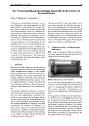
torque uniformly with joint articula<strong>tion</strong>/2/. Fig. 1 shows a constant<br />
velocity drive shaft used in cars.
96 IMW - Institutsmitteilung Nr. 35 (2010)<br />
Figure1: <strong>Constant</strong> velocity drive shaft (after /1/)<br />
The fric<strong>tion</strong> between balls and races leads to high plunging forces<br />
with increasing articula<strong>tion</strong> <strong>of</strong> the joint. Therefore, deteriorate NVH<br />
performance <strong>of</strong> torque transmission /3/. Because <strong>of</strong> fric<strong>tion</strong>, the oscillating<br />
movement <strong>of</strong> the ball is not true rolling but consists <strong>of</strong> rolling,<br />
boring and sliding. Boring and sliding aggravate ball-track fric<strong>tion</strong><br />
and then accelerate the process <strong>of</strong> fatigue. Carsten Bauer investigated<br />
the fatigue, internal fric<strong>tion</strong> and stress <strong>of</strong> CV plunging joint via analysis<br />
as well as experiments, he paid much atten<strong>tion</strong> to deal with the influence<br />
<strong>of</strong> induc<strong>tion</strong> annealing to the internal stress and nondestructive<br />
test <strong>of</strong> the fatigue quantitatively /4/. So, understanding<br />
the dynamic contact <strong>of</strong> ball-races and movement <strong>of</strong> balls will help us<br />
find ways to decrease boring and sliding, therefore, improve the fatigue<br />
life, NVH performance/5/. This paper will apply polygon contact<br />
model (PCM) to simulate the multi-body contact dynamics <strong>of</strong> CV<br />
plunging joint with SIMPACK s<strong>of</strong>tware package, and investigate the<br />
movement <strong>of</strong> the balls under running state.<br />
2 <strong>Multibody</strong> contact model <strong>of</strong> the CV plunging joint<br />
All components <strong>of</strong> CV plunging joint are assembled by mechanical<br />
contacts, leads to a multibody contact system /6/. <strong>Contact</strong>s between<br />
all the components <strong>of</strong> CV plunging joint are shown in Fig. 2. In the<br />
entire joint, there are 24 helical surface-to-sphere contacts (ball-race<br />
contact), 12 sphere-to-plane contacts (ball-cage window contact), 12<br />
sphere-to-cylindrical contacts (ball-cage window contact), and 1
IMW - Institutsmitteilung Nr. 35 (2010) 97<br />
sphere-to -cylindrical contact (cage-outer race contact) and 1 sphereto-sphere<br />
contact (cage-inner race contact).<br />
Figure 2: <strong>Contact</strong>s between components <strong>of</strong> CV plunging joint<br />
Because the races <strong>of</strong> CV plunging joint are helical surface, which<br />
makes most <strong>of</strong> the common contact models are not applicable in this<br />
case. And just because <strong>of</strong> this, there’s few publica<strong>tion</strong>s men<strong>tion</strong>ed the<br />
multi-body contact dynamic simula<strong>tion</strong> <strong>of</strong> CV plunging joint up to<br />
now, though a number <strong>of</strong> multi-body contact dynamic simula<strong>tion</strong>s<br />
are done in CV fixed joint. Recently, Gerhard Hippmann presented a<br />
compliant contact algorithm named Polygonal <strong>Contact</strong> Model (PCM)<br />
to deal with contact between complexity shaped surfaces in multibody<br />
dynamics/7-8/. In PCM, the body surfaces are represented by<br />
polygon meshes, two polygonal surfaces collide if at least one pair <strong>of</strong><br />
intersecting polygons exists, and contact force determina<strong>tion</strong> by the<br />
elastic founda<strong>tion</strong> model and regularized Coulomb’s fric<strong>tion</strong>. This<br />
model facilitated multi-body contact dynamic simula<strong>tion</strong> <strong>of</strong> CV<br />
plunging joint. To relieve the difficulty <strong>of</strong> calcula<strong>tion</strong> and convergence,<br />
the inner race-cage contact and the outer race-cage contact<br />
<br />
are replaced by user defined joints ( X ; , , ). Other contacts are<br />
modeled with PCM.<br />
When a car run in the road, the wheel and wheel plate move up and<br />
down, resulting the plunging <strong>of</strong> the intermediate shaft (see Fig. 1), so<br />
the wheel shaft and wheel plate are also included in the multibody<br />
model, the constant velocity fixed joint is modeled as a “constant ve-
98 IMW - Institutsmitteilung Nr. 35 (2010)<br />
locity joint” in Simpack. The screenshot <strong>of</strong> the whole multibody model<br />
is shown in Fig. 3.<br />
Figure3: Screenshot <strong>of</strong> the multibody model <strong>of</strong> CV plunging joint<br />
3 <strong>Multibody</strong> contact simula<strong>tion</strong> and simula<strong>tion</strong> results<br />
Tab. 1 shows the main dimensions <strong>of</strong> ball plunging CVJ and load<br />
condi<strong>tion</strong>s used in the simula<strong>tion</strong>. The driving torque loaded on the<br />
outer race <strong>of</strong> CV plunging joint and the resisting torque loaded on<br />
the wheel shaft are 1000 N·m and -1000 N·m respectively. The initial<br />
angle velocity <strong>of</strong> the joint is 80 Rad/s.<br />
Ball diameter<br />
d<br />
Effective radius<br />
R<br />
Torque T<br />
<strong>Velocity</strong> ω<br />
22.225 mm 31.95 mm 1000 Nm 80 Rad/s<br />
Table 1: Main dimensions and load condi<strong>tion</strong>s used in the simula<strong>tion</strong><br />
At first, the CV plunging joint is running with fixed articula<strong>tion</strong> angle<br />
10 0 , that’s to say, without plunging. Fig. 4 shows the change <strong>of</strong> contact<br />
forces between balls and races during rota<strong>tion</strong> <strong>of</strong> the joint. The
IMW - Institutsmitteilung Nr. 35 (2010) 99<br />
changes <strong>of</strong> contact forces are consistent with the analytical results<br />
without considering the ball-race fric<strong>tion</strong> in reference /4/. Sawtoothed<br />
curves in Fig. 4 is due to coarse discrete <strong>of</strong> the contact surface<br />
and ball-race fric<strong>tion</strong> in multibody simula<strong>tion</strong>, finer contact surface<br />
mesh will improve the continuity <strong>of</strong> the curve but more calcula<strong>tion</strong><br />
time. Fig. 5 shows the change <strong>of</strong> ball centre posi<strong>tion</strong>, velocity as<br />
well as angle velocity <strong>of</strong> ball1 relative to inner race1 and outer race1<br />
during rota<strong>tion</strong> <strong>of</strong> the joint.<br />
Figure 4: Change <strong>of</strong> contact force between balls and races during rota<strong>tion</strong> <strong>of</strong> the joint (with<br />
fixed articula<strong>tion</strong> angle 10 0 )<br />
Figure 5: Movement <strong>of</strong> ball 1 relative to inner and outer races under fixed articula<strong>tion</strong> angle
100 IMW - Institutsmitteilung Nr. 35 (2010)<br />
When the joint is plunging between 5 0 and 15 0 (with preliminary articulated<br />
angle 10 0 ), the posi<strong>tion</strong> <strong>of</strong> ball centre, velocity and angle velocity<br />
<strong>of</strong> ball1 relative to inner races and outer races are shown in Fig.<br />
6. When the joint enter stable running state, the curve <strong>of</strong> posi<strong>tion</strong>, velocity<br />
and angle velocity are similar to sinusoid, though there’s more<br />
or less devia<strong>tion</strong>. It can be read qualitatively from phase difference between<br />
velocity and angle velocity that the mo<strong>tion</strong> <strong>of</strong> balls is not pure<br />
rolling<br />
Figure 6: Movement <strong>of</strong> ball 1 relative to inner and outer race in plunging<br />
4 Conclusion<br />
The multibody contact simula<strong>tion</strong> <strong>of</strong> constant velocity plunging joint<br />
is carried out in Simpack s<strong>of</strong>tware package using the so named polygonal<br />
contact model (PCM). The change <strong>of</strong> ball-race contact forces,<br />
ball centre posi<strong>tion</strong>, velocity as well as angle velocity <strong>of</strong> balls relative<br />
to inner races and outer races in running states are calculated. They<br />
are consistent with the analytical results before. Further studies will<br />
analyze the kinestate <strong>of</strong> balls relative to races in contact points.
IMW - Institutsmitteilung Nr. 35 (2010) 101<br />
5 References<br />
/1/ http://www.gkndriveline.com/<br />
/2/ Schmelz, F., Seherr-Thoss, H. Aucktor, E.: Universal <strong>Joint</strong>s and<br />
Driveshafts. Springer, Berlin, 2006.<br />
/3/ Baron, E. NVH phenomena in constant-velocity joints - a 3-fold<br />
approach. In Engineering for the customer - FISITA 1992: Automotive<br />
technology serving society. 1992.<br />
/4/ Carsten Bauer. Untersuchungen zu Beanspruchung, Fertigungstechnik,<br />
tribologi -schem Verhalten und Verschleißenprüftechnik<br />
von Kulgel-Gleichlauf-verschiebe -gelenken. Stuttgart,<br />
1988.<br />
/5/ Tawil, M. Lebensdauerprüfung von Gelenkwellen. IMW-<br />
Institutsmitteilung Nr.25, Clausthal 2000<br />
/6/ Serveto, S.M., J-P; Diaby, M, Secondary torque in automotive<br />
drive shaft ball joints: influence <strong>of</strong> geometry and fric<strong>tion</strong> Proc.<br />
IMechE Part K: J. Multi-body Dynamics, 2008. 222(3): p. 215-<br />
227.<br />
/7/ Hippmann, G., An Algorithm for Compliant <strong>Contact</strong> Between<br />
Complexly Shaped Bodies <strong>Multibody</strong> System Dynamics, 2004.<br />
12(4): p. 345-362.<br />
/8/ S. Ebrahimi, G.H., and P. Eberhard, EXTENSION OF THE<br />
POLYGONAL CONTACT MODEL FOR FLEXIBLE MULTIBODY<br />
SYSTEMS. Int. J. <strong>of</strong> Appl. Math. and Mech., 2005. 1: p. 33-50.