BEI HS35 Absolute Optical Encoder - Ä°maj Teknik
BEI HS35 Absolute Optical Encoder - Ä°maj Teknik
BEI HS35 Absolute Optical Encoder - Ä°maj Teknik

You also want an ePaper? Increase the reach of your titles
YUMPU automatically turns print PDFs into web optimized ePapers that Google loves.
40<br />
<strong>BEI</strong> | Page <strong>Absolute</strong> Title <strong>Encoder</strong> Options<br />
Parallel <strong>Absolute</strong> Output<br />
The two most common types of absolute outputs are the Gray Code and the Natural<br />
Binary. Resolution for absolute encoders is expressed in “bits” where each successive<br />
bit increases the resolution by a factor of two. For example, 10 bits = 2 10 =<br />
1024 counts per revolution.<br />
Natural binary code (Figure 1) is constructed so that the code counts up using the<br />
natural sequence of binary counting, i.e. 000, 001, 010, 011, 100 . . etc. The drawback<br />
to using this code sequence is that at several count positions the code will<br />
have transitions on multiple bits simultaneously. Due to the normal variations<br />
caused by gate delays, line impedances, etc. the actual transitions will not occur<br />
simultaneously. Reading data during one of these times could result in an erroneous<br />
reading. This can be overcome by taking multiple readings.<br />
Gray code (Figure 2), by contrast, is designed to avoid the multiple transition problem<br />
entirely. It is specifically constructed so that only one bit will transition at a<br />
time. This ensures that state changes are much less ambiguous to the controller<br />
and is generally considered to be a more robust type of absolute code.<br />
Regardless of the code type, one of the characteristics of absolute encoders is that<br />
they can readily be used for any resolution up to and including their maximum resolution.<br />
For example, a 12 bit encoder can be used at only 8 bits by ignoring (or disconnecting)<br />
the four lowest significant bits (LSB). This enables an installation that<br />
uses multiple absolute encoders to use the same encoder throughout with each<br />
controller using only the bits that it needs.<br />
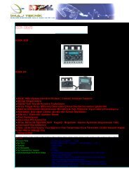
Figure 1 Natural Binary<br />
2 0<br />
(LSB)<br />
2 1<br />
2 2<br />
Figure 2 Gray Code<br />
G0<br />
(LSB)<br />
G1<br />
G2<br />
G3<br />
2 3 ETC. THRU G7 (MSB)<br />
ETC. THRU 2 7 (MSB)<br />
Ordering 8-Bit <strong>Absolute</strong>s<br />
For years, we produced encoders with a maximum resolution of 8 bits. Lots<br />
of those old 8 bit encoders are still around. We update them to newer 12 bit<br />
designs on a case-by-case basis. If you have an 8 bit encoder, here is how<br />
that model number was constructed: Direction of Rotation, Count, Code<br />
and Latch designators were inserted between Shaft Seal Configuration<br />
and Voltage/Output as shown below. To specify an equivalent encoder<br />
based on the 12 bit design, please call our Applications Specialists at 800-<br />
ENCODER (800-362-6337) or check our web site at www.beiied.com.<br />
Direction of Rotation: CCW or CW<br />
Count: 8<br />
Code: GC= Gray Code or NB= Natural Binary<br />
Latch: L= Latch or Blank=None<br />
Output Terminations: EM20=MS3102R20-29P or ED25=DB25P;<br />
SM18 = MS3102R18-1P; C18 = Cable, with length specified in<br />
inches. Specify ED25 for Line Driver Outputs.<br />
Example: H25E-F1-SS-CCW-8GC-28V/V-EM20<br />
(one possible encoder configuration with the 8-Bit <strong>Absolute</strong> Option.)<br />
Serial Synchronous Interface (SSI)<br />
SSI output provides effective synchronization in a closed-loop control system.<br />
A clock pulse train from a controller is used to clock out sensor data: one bit of position<br />
data is transmitted to the controller per one clock pulse received by the sensor.<br />
The use of a differential driver permits reliable transmission of data over long distances<br />
in environments that may be electrically noisy. The encoder utilizes a clock<br />
signal, provided by the user interface, to time the data transmission. Receiving electronics<br />
must include an appropriate receiver as well as line terminating resistors.<br />
Features<br />
• Synchronous transmission<br />
• Transmission lengths to 1000 feet<br />
• Accepts clock rates from 100 KHz to 1.8 MHz<br />
Data Transmission Sequence<br />
1. Output driver of the encoder is a MAX 491 transceiver in transmit mode.<br />
The recommended receiver is a MAX 491 transceiver in receive mode.<br />
2. Controller provides a series of pulses (or differential pulse pairs) on the CLOCK<br />
input lines.<br />
3. On the first HIGH-to-LOW CLOCK transition, the encoder latches its data at the<br />
current position and prepares to transmit.<br />
4. Controller reads data on the falling edge of the next 16 clock cycles.<br />
5. The first bit is a START bit and is always HIGH.<br />
6. Next come 12 data bits beginning with the most significant bit (MSB) and ending<br />
with the least significant bit (LSB). This is followed by three LOW pulses.<br />
7. After the DATA bits, the DATA line goes LOW and remains LOW for a minimum of<br />
30 microseconds between the end of the DATA bits and the beginning of the next<br />
CLOCK series.<br />
Interfacing Long Data Lines<br />
Cable impedance can create a transmission delay, in effect, shifting the phase relationship<br />
between the clock pulse and the data. If this phase shift exceeds 180°,<br />
then the wrong bit position will be sampled by the receiver. As a result, the maximum<br />
allowable clock frequency is a function of the cable length. For 24 AWG,<br />
stranded, 3 pair cable (<strong>BEI</strong> part number 37048-003 or equivalent) the group delay is<br />
1.36ns/ft. The table below shows the maximum transmission rate allowable as a<br />
function of cable length to ensure a phase shift of less than 90°.<br />
CLOCK, Maximum (kHz) = 92,000 / Cable Length (ft)CW<br />
Cable Length (ft) 50 100 200 300 500 1000<br />
Max Freq (kHz) 1800 900 500 300 200 100<br />
SSI Timing<br />
Ordering SSI<br />
HOW TO SPECIFY SSI OUTPUT IN THE ENCODER MODEL NUMBER:<br />
Use the designation, S3 between the Code Format designation<br />
and the Connector designation.<br />
Example: H25D-SS-12GC-S3-CW-SM18<br />
Copyright © 2007 by <strong>BEI</strong> Industrial <strong>Encoder</strong>s | 1-800-ENCODER | www.beiied.com