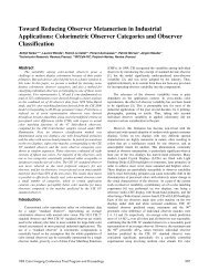
JIST - Society for Imaging Science and Technology
JIST - Society for Imaging Science and Technology
JIST - Society for Imaging Science and Technology

Create successful ePaper yourself
Turn your PDF publications into a flip-book with our unique Google optimized e-Paper software.
<strong>JIST</strong><br />
Vol. 51, No. 1<br />
January/February<br />
2007<br />
Journal of<br />
<strong>Imaging</strong> <strong>Science</strong><br />
<strong>and</strong> <strong>Technology</strong><br />
imaging.org<br />
<strong>Society</strong> <strong>for</strong> <strong>Imaging</strong> <strong>Science</strong> <strong>and</strong> <strong>Technology</strong>
Editorial Staff<br />
Melville Sahyun, editor<br />
sahyun@infionline.net<br />
Donna Smith, production manager<br />
dsmith@imaging.org<br />
Editorial Board<br />
Philip Laplante, associate editor<br />
Michael Lee, associate editor<br />
Nathan Moroney, associate editor<br />
Mitchell Rosen, color science editor<br />
David S. Weiss, associate editor<br />
David R. Whitcomb, associate editor<br />
<strong>JIST</strong> papers are available <strong>for</strong> purchase<br />
at www.imaging.org <strong>and</strong> through<br />
ProQuest. They are indexed in<br />
INSPEC, Chemical Abstracts, <strong>Imaging</strong><br />
Abstracts, COMPENDEX, <strong>and</strong> ISI:<br />
<strong>Science</strong> Citation Index.<br />
Orders <strong>for</strong> subscriptions or single<br />
copies, claims <strong>for</strong> missing numbers,<br />
<strong>and</strong> notices of change of address<br />
should be sent to IS&T via one of the<br />
means listed below.<br />
IS&T is not responsible <strong>for</strong> the accuracy<br />
of statements made by authors <strong>and</strong><br />
does not necessarily subscribe to their<br />
views.<br />
Copyright ©2007, <strong>Society</strong> <strong>for</strong> <strong>Imaging</strong><br />
<strong>Science</strong> <strong>and</strong> <strong>Technology</strong>. Copying<br />
of materials in this journal <strong>for</strong> internal<br />
or personal use, or the internal or personal<br />
use of specific clients, beyond<br />
the fair use provisions granted by the<br />
US Copyright Law is authorized by<br />
IS&T subject to payment of copying<br />
fees. The Transactional Reporting Service<br />
base fee <strong>for</strong> this journal should be<br />
paid directly to the Copyright Clearance<br />
Center (CCC), Customer Service,<br />
508/750-8400, 222 Rosewood Dr.,<br />
Danvers, MA 01923 or online at<br />
www.copyright.com. Other copying<br />
<strong>for</strong> republication, resale, advertising or<br />
promotion, or any <strong>for</strong>m of systematic<br />
or multiple reproduction of any material<br />
in this journal is prohibited except with<br />
permission of the publisher.<br />
Library of Congress Catalog Card<br />
No. 59-52172<br />
Printed in the USA.<br />
<strong>Society</strong> <strong>for</strong> <strong>Imaging</strong> <strong>Science</strong> <strong>and</strong><br />
<strong>Technology</strong><br />
7003 Kilworth Lane<br />
Springfield, VA 22151<br />
www.imaging.org<br />
info@imaging.org<br />
703/642-9090<br />
703/642-9094 fax<br />
Manuscripts should be sent to the<br />
postal address above as describe at<br />
right. E-mail PDF <strong>and</strong> other files as requested<br />
to dsmith@imaging.org.<br />
Guide <strong>for</strong> Authors<br />
Scope: The Journal of <strong>Imaging</strong> <strong>Science</strong> <strong>and</strong> <strong>Technology</strong> (<strong>JIST</strong>) is dedicated to the advancement of imaging science knowledge, the<br />
practical applications of such knowledge, <strong>and</strong> how imaging science relates to other fields of study. The pages of this journal are<br />
open to reports of new theoretical or experimental results, <strong>and</strong> to comprehensive reviews. Only original manuscripts that have not<br />
been previously published nor currently submitted <strong>for</strong> publication elsewhere should be submitted. Prior publication does not refer<br />
to conference abstracts, paper summaries, or non-reviewed proceedings, but it is expected that Journal articles will exp<strong>and</strong> in scope<br />
the presentation of such preliminary communication. Please include keywords on your title <strong>and</strong> abstract page.<br />
Editorial Process/Submission of Papers <strong>for</strong> Review: All submitted manuscripts are subject to peer review. (If a manuscript appears better<br />
suited to publication in the Journal of Electronic <strong>Imaging</strong>, published jointly by IS&T <strong>and</strong> SPIE, the editor will make this recommendation.)<br />
To expedite the peer review process, please recommend two or three competent, independent reviewers. The editorial staff, will<br />
take these under consideration, but is not obligated to use them.<br />
Manuscript Guidelines: Please follow these guidelines when preparing accepted manuscripts <strong>for</strong> submission.<br />
• Manuscripts should be double-spaced, single-column, <strong>and</strong> numbered. It is the responsibility of the author to prepare a succinct,<br />
well-written, paper composed in proper English. <strong>JIST</strong> generally follows the guidelines found in the AIP Style Manual, available<br />
from the American Institute of Physics.<br />
• Documents may be created in Microsoft Word, WordPerfect, or LaTeX/REVTeX.<br />
• Manuscripts must contain a title page that lists the paper title, full name(s) of the author(s), <strong>and</strong> complete affiliation/address <strong>for</strong><br />
each author. Include an abstract that summarizes objectives, methodology, results, <strong>and</strong> their significance; 150 words maximum.<br />
Provide at least four key words.<br />
• Figures should con<strong>for</strong>m to the st<strong>and</strong>ards set <strong>for</strong>th at www.aip.org/epub/submitgraph.html.<br />
• Equations should be numbered sequentially with Arabic numerals in parentheses at the right margin. Be sure to define symbols<br />
that might be confused (such as ell/one, nu/vee, omega/w).<br />
• For symbols, units, <strong>and</strong> abbreviations, use SI units (<strong>and</strong> their st<strong>and</strong>ard abbreviations) <strong>and</strong> metric numbers. Symbols, acronyms,<br />
etc., should be defined on their first occurrence.<br />
• Illustrations: Number all figures, graphs, etc. consecutively <strong>and</strong> provide captions. Figures should be created in such a way that<br />
they remain legible when reduced, usually to single column width (3.3 inches/8.4 cm); see also<br />
www.aip.org/epub/submitgraph.html <strong>for</strong> guidance. Illustrations must be submitted as .tif or .eps files at full size <strong>and</strong> 600 dpi;<br />
grayscale <strong>and</strong> color images should be at 300 dpi. <strong>JIST</strong> does not accept .gif or .jpeg files. Original hardcopy graphics may be sent<br />
<strong>for</strong> processing by AIP, the production house <strong>for</strong> <strong>JIST</strong>. (See note below on color <strong>and</strong> supplemental illustrations.)<br />
• References should be numbered sequentially as citations appear in the text, <strong>for</strong>mat as superscripts, <strong>and</strong> list at the end of the document<br />
using the following <strong>for</strong>mats:<br />
• Journal articles: Author(s) [first/middle name/initial(s), last name], “title of article (optional),” journal name (in italics), ISSN<br />
number (e.g. <strong>for</strong> <strong>JIST</strong> citation, ISSN: 1062-3701), volume (bold): first page number, year (in parentheses).<br />
• Books: Author(s) [first/ middle name/initial(s), last name], title (in italics), (publisher, city, <strong>and</strong> year in parentheses) page reference.<br />
Conference proceedings are normally cited in the Book <strong>for</strong>mat, including publisher <strong>and</strong> city of publication (Springfield, VA, <strong>for</strong> all<br />
IS&T conferences), which is often different from the conference venue.<br />
• Examples<br />
1. H. P. Le, Progress <strong>and</strong> trends in ink-jet printing technology, J. <strong>Imaging</strong> Sci. Technol. 42, 46 (1998).<br />
2. E. M. Williams, The Physics <strong>and</strong> <strong>Technology</strong> of Xerographic Processes (John Wiley <strong>and</strong> Sons, New York, 1984) p. 30.<br />
3. Gary K. Starkweather, “Printing technologies <strong>for</strong> images, gray scale, <strong>and</strong> color,” Proc. SPIE 1458: 120 (1991).<br />
4. Linda T. Creagh, “Applications in commercial printing <strong>for</strong> hot melt ink-jets,” Proc. IS&T’s 10th Int’l. Congress on Adv. In<br />
Non-Impact Printing Technologies (IS&T, Springfield, VA 1994) pp. 446-448.<br />
5. ISO 13655-1996 Graphic technology: Spectral measurement <strong>and</strong> colorimetric computation <strong>for</strong> graphic arts images (ISO,<br />
Geneva), www.iso.org.<br />
6. <strong>Society</strong> <strong>for</strong> <strong>Imaging</strong> <strong>Science</strong> <strong>and</strong> <strong>Technology</strong> website, www.imaging.org, accessed October 2003.<br />
Reproduction of Color: Authors who wish to have color figures published in the print journal will incur color printing charges.<br />
The cost <strong>for</strong> reproducing color illustrations is $490 per page; color is not available to those given page waivers, nor can color page<br />
charges be negotiated or waived. Authors may also choose to have their figures appear in color online <strong>and</strong> in grayscale in the printed<br />
journal. There is no additional charge <strong>for</strong> this, however those who choose this option are responsible <strong>for</strong> ensuring that the captions<br />
<strong>and</strong> descriptions in the text are readable in both color <strong>and</strong> black-<strong>and</strong>-white as the same file will be used in the online <strong>and</strong><br />
print versions of the journal. Only figures saved as TIFF/TIF or EPS files will be accepted <strong>for</strong> posting. Color illustrations may be<br />
also submitted as supplemental material <strong>for</strong> posting on the IS&T website <strong>for</strong> a flat fee of $100 <strong>for</strong> up to five files.<br />
Website Posting of Supplemental Materials: Authors may also submit additional (supplemental) materials related to their articles<br />
<strong>for</strong> posting on the IS&T Website. Examples of such materials are charts, graphs, illustrations, or movies that further explain the<br />
science or technology discussed in the paper. Supplemental materials will be posted <strong>for</strong> a flat fee of $100 <strong>for</strong> up to five files. For<br />
each additional file, a $25 fee will be charged. Fees must be received be<strong>for</strong>e supplemental materials will be posted. As a matter of<br />
editorial policy, appendices are normally treated as supplemental material.<br />
Submission of Accepted Manuscripts: Author(s) will receive notification of acceptance (or rejection) <strong>and</strong> reviewers’<br />
reports. Those whose manuscripts have been accepted <strong>for</strong> publication will receive correspondence in<strong>for</strong>ming them of the issue <strong>for</strong><br />
which the paper is tentatively scheduled, links to copyright <strong>and</strong> page charge <strong>for</strong>ms, <strong>and</strong> detailed instructions <strong>for</strong> submitting accepted<br />
manuscripts. A duly signed transfer of copyright agreement <strong>for</strong>m is required <strong>for</strong><br />
publication in this journal. No claim is made to original US Government works.<br />
Page charges: Page charges <strong>for</strong> the Journal is $80/printed page. Such payment is<br />
not a condition <strong>for</strong> publication, <strong>and</strong> in some circumstances page charges are<br />
waived. Requests <strong>for</strong> waivers must be made in writing to the managing editor prior<br />
to acceptance of the paper <strong>and</strong> at the time of submission.<br />
Manuscripts submissions: Manuscripts should be submitted both electronically<br />
<strong>and</strong> as hardcopy. To submit electronically, send a single PDF file attached to an e-<br />
mail message/cover letter to jist@imaging.org. To submit hardcopy, mail 2 singlespaced,<br />
single-sided copies of the manuscript to: IS&T. With both types of submission,<br />
include a cover letter that states the paper title; lists all authors, with complete<br />
contact in<strong>for</strong>mation <strong>for</strong> each (affiliation, full address, phone, fax, <strong>and</strong> e-mail); identifies<br />
the corresponding author; <strong>and</strong> notes any special requests. Unless otherwise<br />
stated, submission of a manuscript will be understood to mean that the paper has<br />
been neither copyrighted, classified, or published, nor is being considered <strong>for</strong><br />
publication elsewhere. Authors of papers published in the Journal of <strong>Imaging</strong><br />
<strong>Science</strong> <strong>and</strong> <strong>Technology</strong> are jointly responsible <strong>for</strong> their content. Credit <strong>for</strong> the<br />
content <strong>and</strong> responsibility <strong>for</strong> errors or fraud are borne equally by all authors.<br />
JOURNAL OF IMAGING SCIENCE AND TECH-<br />
NOLOGY ( ISSN:1062-3701) is published bimonthly<br />
by The <strong>Society</strong> <strong>for</strong> <strong>Imaging</strong> <strong>Science</strong> <strong>and</strong> <strong>Technology</strong>,<br />
7003 Kilworth Lane, Springfield, VA 22151. Periodicals<br />
postage paid at Springfield, VA <strong>and</strong> at<br />
additional mailing offices. Printed in Virginia,<br />
USA.<br />
<strong>Society</strong> members may receive this journal as part of<br />
their membership. Forty-five dollars ($45.00) of<br />
membership dues are allocated to this subscription.<br />
IS&T members may refuse this subscription by written<br />
request. Domestic institution <strong>and</strong> individual nonmember<br />
subscriptions are $195/year or $50/single<br />
copy. The <strong>for</strong>eign subscription rate is $205/year.<br />
For online version in<strong>for</strong>mation, contact IS&T.<br />
POSTMASTER: Send address changes to JOURNAL<br />
OF IMAGING SCIENCE AND TECHNOLOGY,<br />
7003 Kilworth Lane, Springfield, VA 22151.
<strong>JIST</strong><br />
Vol. 51, No. 1<br />
January/February<br />
2007<br />
Journal of<br />
<strong>Imaging</strong> <strong>Science</strong><br />
<strong>and</strong> <strong>Technology</strong> ®<br />
iii<br />
iv<br />
From the Editor<br />
To the Editor<br />
Feature Article<br />
1 Improved Pen Alignment <strong>for</strong> Bidirectional Printing<br />
Edgar Bernal, Jan P. Allebach, <strong>and</strong> Zygmunt Pizlo<br />
General Papers<br />
23 Characterization of Red-Green <strong>and</strong> Blue-Yellow Opponent Channels<br />
Bong-Sun Lee, Zygmunt Pizlo, <strong>and</strong> Jan P. Allebach<br />
34 High Dynamic Range Image Compression by Fast Integrated Surround<br />
Retinex Model<br />
Lijie Wang, Takahiko Horiuchi, <strong>and</strong> Hiroaki Kotera<br />
44 Illumination-Level Adaptive Color Reproduction Method with Lightness<br />
Adaptation <strong>and</strong> Flare Compensation <strong>for</strong> Mobile Display<br />
Myong-Young Lee, Chang-Hwan Son, Jong-Man Kim,<br />
Cheol-Hee Lee, <strong>and</strong> Yeong-Ho Ha<br />
53 Influence of Paper on Colorimetric Properties of an Ink Jet Print<br />
Marjeta Černi~ <strong>and</strong> Sabina Bra~ko<br />
61 Development of a Multi-spectral Scanner using LED Array <strong>for</strong> Digital<br />
Color Proof<br />
Shoji Yamamoto, Norimichi Tsumura, Toshiya Nakaguchi, <strong>and</strong> Yoichi<br />
Miyake<br />
70 Spectral Color <strong>Imaging</strong> System <strong>for</strong> Estimating Spectral Reflectance<br />
of Paint<br />
Vladimir Bochko, Norimichi Tsumura, <strong>and</strong> Yoichi Miyake<br />
79 Digital Watermarking of Spectral Images Using PCA-SVD<br />
Long Ma, Changjun Li, <strong>and</strong> Shuni Song<br />
86 Qualification of a Layered Security Print Deterrent<br />
Steven J. Simske <strong>and</strong> Jason S. Aronoff<br />
continued on next page<br />
imaging.org<br />
<strong>Society</strong> <strong>for</strong> <strong>Imaging</strong> <strong>Science</strong> <strong>and</strong> <strong>Technology</strong>
IS&T BOARD OF DIRECTORS<br />
President<br />
James R. Milch Jim<br />
Director Medical <strong>Science</strong>s<br />
Eastman Kodak Company<br />
continued from previous page<br />
96 Preparation of Gold Nanoparticles in a Gelatin Layer Film Using Photographic<br />
Materials (5): Characteristics of Gold Nanoparticles Prepared on an Ultrafine Grain<br />
Photographic Emulsion<br />
Ken’ichi Kuge, Tomoaki Nakao, Seiji Saito, Ohiro Hikosaka, <strong>and</strong> Akira Hasegawa<br />
Immediate Past President<br />
James C. King Jim<br />
Principal Scientist<br />
Adobe Systems Incorporated<br />
Executive Vice President<br />
Eric G. Hanson<br />
Department Manager<br />
Hewlett Packard Company<br />
Conference Vice President<br />
Rita Hofmann<br />
Chemist, R&D Manager<br />
Il<strong>for</strong>d <strong>Imaging</strong> Switzerl<strong>and</strong> GmbH<br />
Publication Vice President<br />
Franziska Frey<br />
Assist. Prof., School of Print Media<br />
Rochester Institute of <strong>Technology</strong><br />
Secretary<br />
Ramon Borrell<br />
<strong>Technology</strong> Strategy Director<br />
Hewlett Packard Company<br />
Treasurer<br />
Peter D. Burns<br />
Principal Scientist<br />
Eastman Kodak Company<br />
Vice Presidents<br />
Stefi Baum<br />
Director, Chester F. Carleson Center<br />
<strong>for</strong> <strong>Imaging</strong> <strong>Science</strong><br />
Laura Kitzmann<br />
Marketing Dev. & Comm. Manager<br />
Sensient <strong>Imaging</strong> Technologies, Inc.<br />
Michael A. Kriss<br />
Retired<br />
Howard A. Mizes<br />
Principle Scientist, Xerox Corp.<br />
Jin Mizuguchi<br />
Professor, Yokohama National Univ.<br />
David Weiss<br />
Scientist Fellow, NexPress Solutions,<br />
Inc.<br />
IS&T Conference Calendar<br />
For details <strong>and</strong> a complete listing of conferences, visit www.imaging.org<br />
Electronic <strong>Imaging</strong><br />
IS&T/SPIE 19th Annual Symposium<br />
January 28–February 1, 2007<br />
San Jose, Cali<strong>for</strong>nia<br />
General chairs: Michael A. Kriss<br />
<strong>and</strong> Robert A. Sprague<br />
International Symposium on Technologies <strong>for</strong><br />
Digital Fulfillment<br />
March 3–March 5, 2007<br />
Las Vegas, Nevada<br />
General chair: Stuart Gordon<br />
Archiving 2007<br />
May 21–May 24, 2007<br />
Arlington, Virginia<br />
General chair: Scott Stovall<br />
Ninth International Symposium<br />
on Multispectral Color <strong>Science</strong><br />
<strong>and</strong> Application cosponsored by IS&T<br />
May 30–June 1, 2007<br />
Taipe, Taiwan<br />
General chairs: Tien-Rien Lee <strong>and</strong> Yoichi Miyake<br />
Digital Fabrication Processes Conference<br />
September 16–September 20, 2007<br />
Anchorage, Alaska<br />
General chair: Ross Mills<br />
NIP23: The 23rd International Congress on<br />
Digital Printing Technologies<br />
September 16–September 20, 2007<br />
Anchorage, Alaska<br />
General chair: Ramon Borrell<br />
IS&T/SID’s Fifteenth Color <strong>Imaging</strong><br />
Conference cosponsored by SID<br />
November 5–November 9, 2007<br />
Albuquerque, New Mexico<br />
General chairs: Jan Morovic<br />
<strong>and</strong> Charles Poynton<br />
Chapter Director<br />
Franziska Frey – Rochester<br />
Takashi Kitamura – Japan<br />
Executive Director<br />
Suzanne E. Grinnan<br />
IS&T Executive Director<br />
ii<br />
/
From the Editor<br />
Starting this year, on-line will be the default method <strong>for</strong><br />
IS&T members to receive the Journal of <strong>Imaging</strong> <strong>Science</strong> <strong>and</strong><br />
<strong>Technology</strong>. Many readers already see the Journal on line or<br />
simply download pdf’s of articles of interest. Those without<br />
subscriptions are more likely, as well, to see electronic versions<br />
of the Journal’s articles rather than the original print<br />
hardcopy.<br />
At the same time the number of articles which address<br />
color science, either as the principal focus or a peripheral<br />
issue, is increasing steadily as illustrated by the General Papers<br />
in this issue, eight of which deal with aspects of color<br />
imaging. The number of submissions with respect to all aspects<br />
of imaging science with color illustrations is likewise<br />
increasing; authors expect to be able to illustrate their technical<br />
articles using color. However, fewer authors or their<br />
institutions are willing to subsidize the high cost of color<br />
printing in order to reach the limited audience of the highquality<br />
print edition, <strong>and</strong> are there<strong>for</strong>e opting <strong>for</strong> color online<br />
exclusively. When accurate color in an illustration is<br />
critical to underst<strong>and</strong>ing the content of an article, we need<br />
to establish a process that ensures that our readers of soft<br />
copy versions see the color graphics authentically, in the way<br />
the author(s) intend.<br />
Accordingly our subscribers <strong>and</strong> readers should be enabled<br />
to colorimetrically interpret the color values that sit in<br />
our articles correctly so that they may be viewed appropriately<br />
on their displays <strong>and</strong> printers. Our Editorial Staff has<br />
chosen sRGB as the default color space at this time because<br />
it is necessary in our production workflow to use a color<br />
space that is compatible with both web <strong>and</strong> print publication;<br />
this selection is subject to future revision, i.e., it may be<br />
permanent only as long as there continues to be a dem<strong>and</strong><br />
<strong>for</strong> us to publish a print edition of the Journal. But until that<br />
time, readers of the on-line Journal should calibrate their<br />
displays <strong>and</strong> printers accordingly. We anticipate that authors<br />
in the future may request different color spaces <strong>for</strong> their<br />
illustrations; in that case they will be able to choose a nondefault<br />
space, but will need to supply the Journal with an<br />
appropriate ICC profile.<br />
These topics are treated in more detail in the following<br />
Letter to the Editor, which provides guidelines <strong>for</strong> submission,<br />
display, <strong>and</strong> printing of color imagery in a webpublished<br />
Journal. These guidelines have been kindly providedbyDr.PatrickHerzog.<br />
—M. R. V. Sahyun<br />
iii
Letter to the Editor:<br />
Guidelines <strong>for</strong> the H<strong>and</strong>ling of Color in IS&T Journal Papers<br />
Driven by the nature of our <strong>Society</strong>, color has been one<br />
of the major topics of scientific papers published in this<br />
Journal, <strong>and</strong> it is quite clear that showing research results<br />
frequently has required reproducing color images in true<br />
color. In color reproduction, however, it is difficult to<br />
achieve the required level of color faithfulness, <strong>and</strong> in the<br />
past authors have not been able to af<strong>for</strong>d paying the extra<br />
costs <strong>for</strong> color printing.<br />
Journal papers are now published electronically, <strong>and</strong><br />
color printers <strong>and</strong> monitors have become ubiquitous, so the<br />
scenario is changing, allowing <strong>for</strong> an extensive use of color.<br />
We would like to encourage even more use of color images,<br />
graphics, etc., wherever meaningful <strong>for</strong> the subject, or wherever<br />
appropriate to support the clarity of the paper. However,<br />
h<strong>and</strong>ling color is still not simple in general, <strong>and</strong> its<br />
extensive use may incur additional problems. We intend<br />
these guidelines to keep such problems to a minimum. Accordingly,<br />
we <strong>for</strong>esee different work paths, <strong>and</strong> hope to provide<br />
solutions <strong>for</strong> authors with different levels of color<br />
experience.<br />
Author guidelines<br />
General rules<br />
1. Keep in mind that in the print version of your paper<br />
you may choose to have the figures printed in grayscale,<br />
which may also be the case when readers who<br />
do not have access to color printers, purchase, download,<br />
<strong>and</strong> print the PDF of your article. Hence, you<br />
should make sure that all color images or graphics<br />
also reproduce well in grayscale.<br />
2. The default color space is sRGB (according to ISO/<br />
IEC 61966-2.1). Make sure that all figures, graphics,<br />
etc. have been prepared <strong>for</strong> this color space or converted<br />
into sRGB after preparation.<br />
Why sRGB?<br />
sRGB is the system color space in Windows 2000 <strong>and</strong> XP,<br />
<strong>and</strong> will be the default color space with Windows Vista.<br />
Mac OS does not generally assume sRGB, but has built-in<br />
color management capabilities, so that it will correctly display<br />
images <strong>and</strong> PDFs if they have appropriate profiles embedded.<br />
Moreover, most printer manufacturers assume RGB<br />
data to be sRGB if no color management is used, so that one<br />
should get reasonable results also on office printers.<br />
How to create sRGB data<br />
Non-Color Expert Level<br />
Color conversions are carried out by means of a color management<br />
system using color profiles (ICC profiles). If you do<br />
not know how to create the proper color trans<strong>for</strong>ms, you are<br />
unlikely to require high color fidelity. To create a file properly,<br />
follow the simple guidelines given here.<br />
Simple Guidelines <strong>for</strong> Achieving sRGB-like behavior on PCs<br />
If you are using Windows 2000, XP, or Vista, then your system’s<br />
default color space is sRGB. This is good news. Moreover,<br />
most monitor manufacturers have adopted the sRGB<br />
st<strong>and</strong>ard in a way that every monitor by default approximates<br />
sRGB. This approximation does not guarantee color<br />
accuracy, but it does ensure that the computer/monitor system<br />
is not entirely off in terms of color. In other words: If<br />
you display a graphic or image on your system, <strong>and</strong> you like<br />
what you see, then it is safe <strong>for</strong> you to claim that the data<br />
was prepared <strong>for</strong> sRGB.<br />
Important Note: A precondition is that you have not<br />
modified the entire system, neither in terms of the operating<br />
system’s color settings, nor in terms of the monitor. If you<br />
have modified color temperature, color balance, RGB gains,<br />
etc., the display most probably no longer follows an approximate<br />
sRGB state. In this case try to reset the monitor to its<br />
default settings using the onscreen menu.<br />
Simple Guidelines <strong>for</strong> Achieving sRGB-like behavior<br />
on Macs<br />
If you are using a Macintosh, the default setup is different<br />
than sRGB. The main difference is that the Mac uses a<br />
gamma of 1.8 instead of the 2.2 of sRGB. If you do not<br />
know how to convert color images into another color space,<br />
we recommend changing the default setting. Just open the<br />
Monitor Control Panel from the System Preferences menu,<br />
click on the “Colors” tab, <strong>and</strong> press the “Calibrate” button.<br />
If your monitor is in good shape, you can use the nonexpert<br />
mode. Set the gamma correction to “2.2 TV gamma,”<br />
<strong>and</strong> the desired color temperature to “D65” or “uncorrected.”<br />
Some monitors, e.g., LCD, provide a greater luminance<br />
range at a slightly lower color temperature, e.g., D60,<br />
which may, in that case, be a better compromise. Note: Do<br />
not per<strong>for</strong>m this manual correction if you are using a monitor<br />
calibration system (see below).<br />
Making use of Monitor Calibration Tools<br />
If you are using monitor calibration hard- <strong>and</strong>/or software,<br />
the sRGB state may also be void. In this case, you should use<br />
color conversion software (e.g., Photoshop) to convert the<br />
data into sRGB using your up-to-date monitor profile as a<br />
source profile <strong>and</strong> the sRGB profile as destination profile. If<br />
you do not know how to do this, carry out the following<br />
instead: Rerun your monitor calibration system <strong>and</strong> choose<br />
an sRGB setting if possible, or at least set the target gamma<br />
to 2.2 <strong>and</strong> the white point to D65 (or 6500 K).<br />
iv
Summary<br />
To summarize, there are two ways to achieve the required<br />
sRGB based color data. The first one is to put the computer<br />
<strong>and</strong> monitor in a state where it approximates sRGB. In this<br />
case, you can take any color data as perceived on the monitor<br />
as valid. The second way is to leave the computer/<br />
monitor as it is, <strong>and</strong> to have a valid color profile available.<br />
Prepare all the color data so that you are happy with them.<br />
Afterwards, use the monitor profile as source profile <strong>and</strong><br />
sRGB as destination profile <strong>and</strong> convert the data into sRGB.<br />
Color Expert Level<br />
We assume that you know how to convert color data into<br />
sRGB. If in doubt, follow the guidelines <strong>for</strong> non-color experts.<br />
We recommend that all color images have the sRGB<br />
profile embedded. Do not use color spaces different than<br />
sRGB even if embedded profiles in principle allow <strong>for</strong> this:<br />
Many web browsers or PDF viewers may not support embedded<br />
profiles, hence display <strong>and</strong> print quality may be<br />
compromised.<br />
Color Plate Appendix<br />
If you feel that sRGB limits your color data unacceptably,<br />
there is the option to include an appendix of color plates,<br />
which will not appear in the published paper version of the<br />
journal, but will be available as Supplemental Material on<br />
the IS&T website. For these color plates you can use any<br />
color space that can be described by a matrix profile (do not<br />
use LUT profiles!). It is m<strong>and</strong>atory that every image here has<br />
the respective profile embedded. You can replicate any image<br />
of the main text in the color appendix, <strong>and</strong> also add further<br />
images (at the discretion of the Editorial <strong>and</strong> Production<br />
Staff). You should add a description of how the images have<br />
been prepared, <strong>and</strong> what the reader should do in order to<br />
achieve an appropriate reproduction, i.e., specify the rendering<br />
intent. If the color space is large, an appropriate reproduction<br />
may be possible only on a monitor, or on a specific<br />
type of large gamut printer, etc. Let the readers know this.<br />
Readers’ Guidelines<br />
All color images in the main body of every paper have been<br />
prepared <strong>for</strong> sRGB.<br />
Monitor Viewing of Color Articles<br />
The best way to enable faithful viewing of color images in<br />
articles is a calibrated display with a properly installed monitor<br />
profile. If you possess a monitor calibrator, make sure<br />
that the monitor is properly calibrated <strong>and</strong> profiled. If not,<br />
<strong>and</strong> you have a Mac, nothing else is required; just make sure<br />
that the monitor settings are somewhat reasonable (white<br />
does not look pink etc.). If you don’t have a monitor calibrator<br />
<strong>and</strong> you have a PC, follow the guidelines in the section<br />
above, “Simple Guidelines <strong>for</strong> Achieving sRGB-like behavior<br />
on PCs.”<br />
On the Macintosh, most known PDF viewing software<br />
(including Preview <strong>and</strong> Acrobat) obeys embedded color profiles.<br />
In Windows, Acrobat also supports profiles, <strong>and</strong> makes<br />
use of monitor profiles, but defaults to sRGB if none has<br />
been installed on the system.<br />
Printing of Color Articles<br />
Printing color is less predictable than displaying color on a<br />
monitor. Depending on the printer type, paper, inks, printing<br />
speed, driver settings, etc., quite different results may<br />
occur. Though printer profiling can correct deviate color<br />
behavior, it cannot per<strong>for</strong>m magic given sometimes very<br />
limited color gamuts. Hence, if color quality is essential to an<br />
article, make sure that you use a good printer with reasonable<br />
inks, quality coated paper, <strong>and</strong> high-quality driver<br />
settings.<br />
If you know how to profile a printer, make use of this<br />
capability. Otherwise we recommend using the default settings<br />
of the printer driver, which should lead to reasonable<br />
results, since most printer manufacturers assume, more or<br />
less, an sRGB color space <strong>for</strong> the source data, i.e., the color<br />
space <strong>for</strong> which the article images have been prepared.<br />
If the author(s) have included a color plate appendix<br />
with specially prepared images (larger color gamut etc.) they<br />
should also have provided special guidelines to get to the<br />
desired result, e.g., by specifying the rendering intent. These<br />
color plates are usually intended <strong>for</strong> experts who should<br />
strictly follow the authors’ directives, <strong>and</strong> employ color<br />
management.<br />
Appendix<br />
To check if your system obeys color profiles, the following<br />
site provides a test document with a simple test to see if a<br />
PDF viewer supports embedded profiles: http://<br />
www.color.org/version4ready.html.<br />
—Patrick Herzog<br />
X-Rite, Inc.<br />
v
IS&T Corporate Members<br />
IS&T Corporate Members provide significant financial support, thereby assisting the <strong>Society</strong> in achieving its goals of<br />
disseminating in<strong>for</strong>mation <strong>and</strong> providing professional services to imaging scientists <strong>and</strong> engineers. In turn, the <strong>Society</strong><br />
provides a number of material benefits to its Corporate Members. For complete in<strong>for</strong>mation on the Corporate Membership<br />
program, contact IS&T at info@imaging.org.<br />
Sustaining Corporate Members<br />
Adobe Systems Inc.<br />
345 Park Avenue<br />
San Jose, CA 95110-2704<br />
Canon USA Inc.<br />
One Canon Plaza, Lake Success<br />
New York, NY 11042-1198<br />
Eastman Kodak Company<br />
343 State Street<br />
Rochester, NY 14650<br />
Hewlett-Packard Company<br />
1501 Page Mill Road<br />
Palo Alto, CA 94304<br />
Supporting Corporate Members<br />
Lexmark International, Inc.<br />
740 New Circle Road NW<br />
Lexington, KY 40511<br />
Xerox Corporation<br />
Wilson Center <strong>for</strong> Research <strong>and</strong><br />
<strong>Technology</strong><br />
800 Phillips Road<br />
Webster, NY 14580<br />
Fuji Photo Film Company, Ltd.<br />
210 Nakanuma, Minami-ashigara<br />
Kanagawa 250-0193 Japan<br />
Konica Minolta Holdings Inc.<br />
No. 1 Sakura-machi<br />
Hino-shi, Tokyo 191-8511 Japan<br />
Donor Corporate Members<br />
ABBY USA Software House, Inc.<br />
47221 Fremont Blvd.<br />
Fremont, CA 94538<br />
ILFORD <strong>Imaging</strong> Switzerl<strong>and</strong> GmbH<br />
Route de l’Ancienne Papeterie 1<br />
CH-1723 Marly, Switzerl<strong>and</strong><br />
Axis Communications AB<br />
Embdalavägen 14<br />
SE-223 69 Lund, Sweden<br />
Cheran Digital <strong>Imaging</strong> & Consulting, Inc.<br />
798 Burnt Gin Road<br />
Gaffney, SC 29340<br />
Clariant Produkte GmbH<br />
Division Pigments & Additives<br />
65926 Frankfurt am Main Germany<br />
Felix Schoeller Jr. GmbH & Co. KG<br />
Postfach 3667<br />
D-49026 Osnabruck, Germany<br />
Ferrania SpA<br />
Viale Martiri Della Liberta’ 57<br />
Ferrania (Savona) I-17014<br />
GretagMacbeth<br />
Logo GmbH & Co. KG<br />
Westfälischer Hof Garbrock 4<br />
48565 Steinfurt, Germany<br />
Hallmark Cards, Inc.<br />
Chemistry R & D<br />
2501 McGee, #359<br />
Kansas City, MO 64141-6580<br />
MediaTek Inc.<br />
No. 1 Dusing Rd., 1<br />
Hsinchu 300 R.O.C, Taiwan<br />
Nitta Gelatin NA Inc.<br />
201 W. Passaic Street<br />
Rochelle Park, NJ 07662-3100<br />
Pantone, Inc.<br />
590 Commerce Blvd.<br />
Carlstadt, NJ 07072-3098<br />
Quality Engineering Associates (QEA),<br />
Inc.<br />
99 South Bed<strong>for</strong>d Street, #4<br />
Burlington, MA 01803<br />
The Ricoh Company, Ltd.<br />
16-1 Shinei-cho, Tsuzuki-ku<br />
Yokohama 224-0035 Japan<br />
Sharp Corporation<br />
492 Minosho-cho, Yamatokoriyama<br />
Nara 639-1186 Japan<br />
Sony Corporation/<br />
Sony Research Center<br />
6-7-35 Kita-shinagawa<br />
Shinagawa, Tokyo 141 Japan<br />
as 12/3/06
Journal of <strong>Imaging</strong> <strong>Science</strong> <strong>and</strong> <strong>Technology</strong>® 51(1): 1–22, 2007.<br />
© <strong>Society</strong> <strong>for</strong> <strong>Imaging</strong> <strong>Science</strong> <strong>and</strong> <strong>Technology</strong> 2007<br />
Improved Pen Alignment <strong>for</strong> Bidirectional Printing<br />
Edgar Bernal <strong>and</strong> Jan P. Allebach<br />
School of Electrical <strong>and</strong> Computer Engineering, Purdue University, West Lafayette, IN 47907-1285<br />
E-mail: eabernal@purdue.edu<br />
Zygmunt Pizlo<br />
Department of Psychological <strong>Science</strong>s, Purdue University, West Lafayette, IN 47907-1285<br />
Abstract. The quality of the prints produced by an ink jet printer is<br />
highly dependent on the characteristics of the dots produced by the<br />
ink jet pens. While some literature discusses metrics <strong>for</strong> the objective<br />
evaluation of print quality, few of the ef<strong>for</strong>ts have combined<br />
automated quality tests with subjective assessment. The authors<br />
develop an algorithm <strong>for</strong> analyzing printed dots <strong>and</strong> study the effect<br />
of the dot characteristics on perceived print alignment. The authors<br />
establish the perceptual preferences of human observers via a set<br />
of psychophysical experiments.<br />
© 2007 <strong>Society</strong> <strong>for</strong> <strong>Imaging</strong> <strong>Science</strong> <strong>and</strong> <strong>Technology</strong>.<br />
DOI: 10.2352/J.<strong>Imaging</strong>Sci.Technol.200751:11<br />
INTRODUCTION<br />
The advent of low cost, photo-quality ink jet printers has<br />
raised the need <strong>for</strong> an objective means of determining print<br />
quality that is consistent with what the end-user perceives.<br />
High level quality metrics have been specified in the International<br />
Association <strong>for</strong> St<strong>and</strong>ardization/International Electrotechnical<br />
Commission (ISO/IEC) guidelines on hardcopy<br />
print assessment. 1 These guidelines include metrics <strong>for</strong> four<br />
distinct categories of printed areas: line <strong>and</strong> character metrics,<br />
solid fill metrics, tint solid metrics, <strong>and</strong> background<br />
field metrics. Other metrics that enable the quantification of<br />
per<strong>for</strong>mance aspects relevant to ink jet printers have also<br />
been proposed. These aspects include color registration,<br />
color consistency, modulation transfer function (MTF), text<br />
quality, sharpness, 2 dot quality, <strong>and</strong> line quality. 3,4<br />
Multiple ef<strong>for</strong>ts have been made to automate the process<br />
of image quality assessment both during product<br />
development 5 <strong>and</strong> manufacturing, 6 <strong>and</strong> <strong>for</strong> benchmarking<br />
<strong>and</strong> competitive analysis. 4,7 The ultimate objective of these<br />
initiatives is to provide the ability to measure a large volume<br />
of prints <strong>and</strong>, at the same time, achieve the repeatability <strong>and</strong><br />
objectivity that visual inspection-based processes lack.<br />
Attempts have also been made to characterize <strong>and</strong> reduce<br />
print quality defects inherent to ink jet technology,<br />
such as the inability to achieve uni<strong>for</strong>mity in areas of solid<br />
color because of b<strong>and</strong>ing, 8 printing artifacts derived from<br />
incorrect dot placement, 9 dot shapes <strong>and</strong> sizes that differ<br />
from the ideal, 10 <strong>and</strong> the presence of tails <strong>and</strong> satellites due<br />
to aerodynamic effects. 11<br />
Received Jul. 31, 2006; accepted <strong>for</strong> publication Oct. 11, 2006.<br />
1062-3701/2007/511/1/22/$20.00.<br />
Low level models have also been used to improve the<br />
quality of printed halftone images. There are two approaches<br />
to the development of such model-based algorithms. 12 The<br />
first approach uses models that reflect the actual process<br />
whereby the digital halftone is trans<strong>for</strong>med to colorant on<br />
the page. For example, models <strong>for</strong> the laser beam, exposure<br />
of the organic photoconductor, <strong>and</strong> the resulting absorptance<br />
on the paper have been embedded into the Direct<br />
Binary Search (DBS) halftoning algorithm <strong>for</strong> electrophotographic<br />
(EP) printers, 13 showing good improvement over<br />
regular binary DBS with tone correction. The second approach<br />
is largely based on characterization of the halftone<br />
image as it exists on the printed page. For example, analytical<br />
<strong>and</strong> stochastic models <strong>for</strong> EP printer dot interactions<br />
have been incorporated in the DBS halftoning algorithm, 14<br />
yielding enhanced detail rendition <strong>and</strong> improved tonal gradation<br />
in shadow areas. For ink jet printers, the displacement<br />
<strong>and</strong> profile of individual dots were measured <strong>and</strong> the<br />
conditional pixel statistics were calculated. 15 These results<br />
were then applied to the DBS halftoning algorithm to develop<br />
an ink jet printer model that reduced the visual<br />
artifacts caused by systematic <strong>and</strong> r<strong>and</strong>om errors in dot<br />
placement.<br />
An ink jet printer places marks on the page by means of<br />
a print head that contains columns of nozzles through which<br />
ink is fired. The nozzles are fired in a carefully controlled<br />
manner as the print head moves back <strong>and</strong> <strong>for</strong>th across the<br />
page. Careful alignment of the dot patterns printed in successive<br />
passes across the page is critical to perceived print<br />
quality. The aim of this paper is to study the effects of the<br />
printed dot characteristics on the perception of ink jet pen<br />
alignment via an approach that relies both on automated<br />
image analysis tools <strong>and</strong> psychophysical experiments. We develop<br />
a set of image analysis tools to characterize many attributes<br />
of printed dots, including alignment. We also examine<br />
the relationship between physical alignment <strong>and</strong><br />
perceived alignment. This paper focuses on the HP DeskJet<br />
6540 (Hewlett-Packard Company, 3000 Hanover St., Palo<br />
Alto, CA 94304-1185) high resolution ink jet printer with<br />
plain paper, but the methodology is generally applicable to<br />
other ink jet printers <strong>and</strong> paper types as well.<br />
The structure of the paper is as follows: we first give an<br />
overview of the ink jet printing process. We then describe<br />
the calibration of the image capture device <strong>and</strong> the design of<br />
1
Bernal, Allebach, <strong>and</strong> Pizlo: Improved pen alignment <strong>for</strong> bidirectional printing<br />
the tools that enable alignment measurement <strong>and</strong> dot analysis.<br />
We present some experimental results obtained from the<br />
application of the dot analysis tool to test prints. We proceed<br />
to describe the set of psychophysical experiments that were<br />
per<strong>for</strong>med on alignment perception. Finally, we give our<br />
conclusions.<br />
PRELIMINARIES<br />
Figure 1 illustrates the operation of a typical ink jet printer.<br />
The paper is advanced through the unit by a series of rollers<br />
driven by a stepper motor. A carriage transports the pen or<br />
printhead back <strong>and</strong> <strong>for</strong>th across the page. The printhead<br />
consists of one or more columns of nozzles through which<br />
drops of ink are fired onto the surface of the paper. Printed<br />
dots reveal artifacts that depend on print options such as<br />
print resolution, speed, directionality, <strong>and</strong> the number of<br />
printing passes over each pixel on the paper. A print mode<br />
specifies the set of such print options with which a document<br />
is printed. The pixels that are printed in a given pass<br />
across the page comprise a subset of the pixels in a horizontal<br />
b<strong>and</strong> with height equal to the height of the print head.<br />
This horizontal b<strong>and</strong> of pixels is called a swath. In the<br />
single-pass print modes, the printhead passes only once over<br />
each position on the paper, so the swaths do not overlap. For<br />
a multipass print mode with N passes, the paper only advances<br />
a fraction 1/N of the height of the printhead between<br />
passes. With the single pass print modes, misalignment between<br />
adjoining swaths is especially visible. With multipass<br />
modes, the misalignment is masked to some extent by the<br />
overlapping swaths. Typically, a print mode with one pass, a<br />
higher printhead velocity, <strong>and</strong> lower resolution is used <strong>for</strong><br />
draft quality printing <strong>and</strong> a mode with multiple passes, a<br />
lower printhead velocity, <strong>and</strong> a higher resolution is used <strong>for</strong><br />
the highest quality printing. To achieve print resolutions that<br />
are lower than the native resolution of the print mechanism,<br />
two or more dots are printed in a cluster <strong>for</strong> each pixel.<br />
In this paper, we are primarily interested in draft quality<br />
printing of black <strong>and</strong> white documents using a single pass<br />
mode. This modus oper<strong>and</strong>i implies that there is a tradeoff<br />
between print speed <strong>and</strong> print resolution. To see this, consider<br />
the simpler case in which the printhead has only one<br />
column of nozzles <strong>and</strong> is moving at a speed of v inches<br />
per second (ips) across the page. Suppose also that the<br />
maximum frequency at which the nozzles can be fired is f<br />
firings/sec. Then, the closest distance at which two horizontally<br />
adjacent dots can be printed is d=v/f in., <strong>and</strong> the<br />
maximum resolution that can be achieved with that particular<br />
print mode is 1/d dots per inch (dpi). Since f is fixed <strong>for</strong><br />
a given printhead, the print resolution is inversely proportional<br />
to the print speed. In unidirectional print modes, the<br />
pen only fires ink while it is traveling in one direction across<br />
the page (either while traveling from left to right or from<br />
right to left), while in bidirectional print modes, successive<br />
swaths are printed in opposite directions.<br />
When printing at a resolution of 300 dpi, the DeskJet<br />
6540, which has a pen with vertical nozzle-to-nozzle spacing<br />
of 1/600 in., renders a single dot as two vertically adjacent<br />
dots. However, given the high nozzle firing frequency required<br />
to print at high carriage speeds, some of the nozzles<br />
fail to fire ink occasionally, which results in some single dots<br />
being printed on the page. Figure 2 shows typical single <strong>and</strong><br />
double dots printed at a carriage speed of 30 ips <strong>and</strong><br />
scanned at 7000 dpi with a QEA IAS-1000 Automated Image<br />
Analysis System (Quality Engineering Associates Inc, 25<br />
Adams Street, Burlington, MA 01803).<br />
Figure 3 shows the appearance of a typical dot printed<br />
with a single-pass, 300 dpi resolution print mode with different<br />
carriage speeds <strong>and</strong> printing directions. It illustrates<br />
the fact that as print speed increases, the dot shape becomes<br />
more asymmetric, <strong>and</strong> thus more dependent on the printing<br />
direction. Other artifacts that are related to print speed are<br />
Figure 1. Operation of an ink jet printer: a the 3-D view illustrates the<br />
movement of the printhead <strong>and</strong> b the cross-section illustrates the paper<br />
path.<br />
Figure 2. Effect of print resolution on dot appearance: a single dot <strong>and</strong><br />
b double dot printed with 300 dots per inch dpi, 30 inches per second<br />
ips, right-to-left print mode. Scanned at 7000 dpi with QEA<br />
IAS-1000.<br />
2 J. <strong>Imaging</strong> Sci. Technol. 511/Jan.-Feb. 2007
Bernal, Allebach, <strong>and</strong> Pizlo: Improved pen alignment <strong>for</strong> bidirectional printing<br />
Figure 4. Other artifacts due to high print speeds: a satellites <strong>and</strong> b<br />
tails on dots printed at 300 dpi, 60 ips, right-to-left print mode. Scanned<br />
at 7000 dpi with QEA IAS-1000.<br />
Figure 3. Typical dot printed at 300 dpi: a 15 ips left-to-right print<br />
mode, b 45 ips left-to-right print mode, <strong>and</strong> c 45 ips right-to-left print<br />
mode. Scanned at 7000 dpi with QEA IAS-1000.<br />
tails <strong>and</strong> satellites, which occur when the drop of ink breaks<br />
up as it exits the print nozzle. If the secondary droplet breaks<br />
away completely from the main droplet, it <strong>for</strong>ms a satellite<br />
[see Fig. 4(a)], <strong>and</strong> if it breaks away only partially, it <strong>for</strong>ms a<br />
tail [see Fig. 4(b)]. Tails <strong>and</strong> satellites usually trail the main<br />
dot relative to the direction of travel of the pen. Since there<br />
is a tradeoff between print quality <strong>and</strong> print speed <strong>and</strong> also<br />
because the media characteristics <strong>and</strong> page content impact<br />
the choice of print mode that will yield the best print quality,<br />
a number of different print modes are typically designed <strong>for</strong><br />
an ink jet printer. The specific effect of the print modes on<br />
the dot attributes will be described in detail later.<br />
The process of printing a vertical line with a single-pass,<br />
bidirectional mode is illustrated in Fig. 5 <strong>for</strong> a simplified<br />
printer architecture. The printhead contains nozzles (in this<br />
case, 3 columns of 8 nozzles each) that fire the colorant onto<br />
the page. Typically, a real printhead would contain many<br />
more nozzles. For example, the black ink printhead <strong>for</strong> the<br />
HP DeskJet 6540 printer contains 4 columns of 168 nozzles<br />
each. The two-dimensional image of the line (including the<br />
blank regions surrounding the line) is encoded onto a print<br />
mask, 16 which consists of a two-dimensional array of 0’s <strong>and</strong><br />
1’s. A 1 indicates firing the nozzle at that particular position<br />
<strong>and</strong> a 0 indicates no firing. In the case illustrated by Fig. 5,<br />
the upper segment of the vertical line is printed on the leftto-right<br />
pass of the pen <strong>and</strong> the lower segment is printed on<br />
the right-to-left pass. The size of each swath is determined<br />
by the distance between the top <strong>and</strong> bottom nozzles in the<br />
pen.<br />
Vertical alignment within a swath is readily achieved via<br />
the fixed spatial positions of the nozzles in the printhead,<br />
<strong>and</strong> between swaths by the correct advancement of the paper.<br />
Horizontal alignment within a swath is also readily<br />
achieved by virtue of the fixed spatial configuration of the<br />
nozzles in the print head, <strong>and</strong> through synchronized firing of<br />
J. <strong>Imaging</strong> Sci. Technol. 511/Jan.-Feb. 2007 3
Bernal, Allebach, <strong>and</strong> Pizlo: Improved pen alignment <strong>for</strong> bidirectional printing<br />
ink jet printer <strong>and</strong> scanned with the Aztek Premier high<br />
resolution drum scanner (Aztek Digital <strong>Imaging</strong>, 13765-F<br />
Alton Parkway, Irvine, CA 92618). We developed a software<br />
tool that classifies <strong>and</strong> quantifies the printed dot characteristics<br />
<strong>and</strong> calculates the relative position of adjacent swaths<br />
from the scanned version of the test pattern. To match the<br />
perceived attributes <strong>and</strong> the measured quantities, we used a<br />
set of test pages encoded in a low level printing language as<br />
the stimuli in the psychophysical experiments. The low level<br />
printing language allows fine tuning of the swath-to-swath<br />
offsets as well as print speeds <strong>and</strong> print directions.<br />
Figure 5. Illustration of the process of printing a vertical line in a singlepass,<br />
bidirectional print mode, with a 24-nozzle pen. The vertical position<br />
of the pen with respect to the media changes from swath to swath as the<br />
paper is advanced.<br />
the nozzles while the print head moves at constant velocity.<br />
Between swaths, horizontal alignment depends on the timing<br />
of the start of the firing of nozzles at the initial edge of<br />
the page. Consequently, swath-to-swath horizontal alignment<br />
is the factor that ultimately determines whether or not<br />
the print appears aligned to the viewer. Figure 5 illustrates<br />
the situation where an undesired line break is produced due<br />
to inaccurate horizontal alignment between swaths. In reality,<br />
however, the line segments printed on each of the swaths<br />
are more complex than those depicted in the figure. This is<br />
because of the dot irregularities <strong>and</strong> the fact that the relationship<br />
between the main dot <strong>and</strong> tails or satellites is reversed<br />
from raster to raster. Thus, the task of achieving accurate<br />
swath-to-swath alignment requires knowledge of how<br />
the human viewer actually perceives the position of the main<br />
dot/satellite or main dot/tail pair.<br />
The ability of the human viewer to detect misalignment<br />
has been widely studied in cases where the line segments are<br />
displayed or printed with ideal devices. The just noticeable<br />
angular offset between two line segments is called Vernier<br />
acuity. 17 It has been found that the discriminable offset<br />
ranges from 5 to 10 seconds of arc (2.910 −4 in. to 5.8<br />
10 −4 in. at a viewing distance of 12 in.), which is much<br />
less than the distance of 25 seconds of arc between foveal<br />
receptors. However, few studies have considered the case<br />
where the lines are composed of irregular dots. Patel et al.<br />
found that thresholds <strong>for</strong> asymmetric irregular shapes were<br />
higher than those <strong>for</strong> regular dots. 18 Since dots become more<br />
irregular as the print speed increases, evaluation of alignment<br />
perception at high print speeds (45 ips <strong>and</strong> above) is<br />
of particular interest. Also, since higher print speeds imply<br />
lower print resolutions, the test resolution was fixed at<br />
300 dpi <strong>for</strong> the fastest print modes. This is the highest resolution<br />
achievable at the highest print speed <strong>for</strong> this printer.<br />
To enable automatic measurement of the print characteristics,<br />
we designed a test pattern that is printed with an<br />
PREPROCESSING<br />
The alignment measurement procedure consists of printing,<br />
scanning, <strong>and</strong> processing a test pattern in order to get dot<br />
placement in<strong>for</strong>mation. Even though the images obtained<br />
with the QEA System are sharper than those obtained with<br />
the Aztek Scanner, the latter was chosen <strong>for</strong> this task due to<br />
its larger field of view at high resolutions. The alignment<br />
analysis tool relies on averaging dot positions across a large<br />
number of dots that cover a printed area of approximately<br />
1 in.1 in. The Aztek Scanner is capable of capturing a<br />
region of 8.5 in.11 in. regardless of the scanning resolution,<br />
while the field of view of the QEA is less than 0.1 in.<br />
0.1 in. at 8000 dpi. In this section, the scanner calibration<br />
procedure that allows the mapping of the scanner grayscale<br />
output into absorptance is described. Also, the design of the<br />
test pattern <strong>and</strong> the initial processing to find boundaries<br />
between dots are presented.<br />
Scanner Calibration<br />
Scanner calibration is the process whereby device-dependent<br />
scanner RGB values are converted into values of a deviceindependent<br />
color space such as CIE XYZ. 19 The scanner<br />
calibration was per<strong>for</strong>med as suggested in Ref. 20:<br />
1. A TIFF file containing 17 half-inch square test<br />
patches with gray values ranging from 0 to 1 was<br />
generated.<br />
2. The TIFF file was printed using the printer driver’s<br />
halftoning technique at 600 dpi. The same printer<br />
<strong>and</strong> the same colorant (K) used in the alignment<br />
study were used in the calibration process.<br />
3. The luminance values of the patches were measured<br />
with a calibrated Gretag SPM-50 (Gretag Data <strong>and</strong><br />
Image Systems, Althardstrasse 70, CH-8105 Regensdorf,<br />
Zürich, Switzerl<strong>and</strong>) spectrophotometer. Five<br />
measurements were taken <strong>for</strong> each patch <strong>and</strong> the results<br />
were averaged. The resulting luminance was<br />
converted to absorptance (0–1) values <strong>and</strong> then rescaled<br />
to fall in the range 0–255.<br />
4. The patches were scanned at 1000 dpi with the Aztek<br />
Premier drum scanner. The resulting patch images<br />
were cropped to avoid edge effects, <strong>and</strong> the average<br />
grayscale value of each patch was found.<br />
5. The scanner data S was fitted to the spectrophotometer<br />
data G using an exponential function of the<br />
<strong>for</strong>m G=a 1 S/255 +a 2 by minimizing the mean-<br />
4 J. <strong>Imaging</strong> Sci. Technol. 511/Jan.-Feb. 2007
Bernal, Allebach, <strong>and</strong> Pizlo: Improved pen alignment <strong>for</strong> bidirectional printing<br />
squared error between the function output <strong>and</strong> the<br />
data points. The resulting coefficients were<br />
a 1 =262.48, =1.23, <strong>and</strong> a 2 =5.02.<br />
6. Be<strong>for</strong>e any scanned image is processed, it is calibrated<br />
using this mapping. The raw data <strong>and</strong> the<br />
fitted curve are shown in Fig. 6.<br />
Test Pattern Design <strong>and</strong> Dot Boundary Calculation<br />
The first step toward pen characterization consists of designing<br />
a test pattern with attributes that enable the measurement<br />
of the quantities of interest. In our case, we are interested<br />
in being able to measure swath-to-swath alignment<br />
<strong>and</strong> to quantify dot characteristics such as shape, size, elongation,<br />
<strong>and</strong> presence or absence of artifacts, such as tails <strong>and</strong><br />
satellites.<br />
The test pattern we designed is a 600600 pixel grid<br />
where only every 20th row <strong>and</strong> 20th column contains a<br />
printed dot. Hence, there are a total of 900 dots in the<br />
printed test pattern. In order to facilitate scanner focusing<br />
<strong>and</strong> to stabilize the pen’s nozzle firing, a 50-pixel-wide solid<br />
frame surrounds the central grid, <strong>and</strong> a 400 pixel<br />
400 pixel solid black region is placed on each side of the<br />
frame. Figure 7 shows the designed test pattern.<br />
The test pattern is printed in the desired print mode<br />
(the dot analysis tool works <strong>for</strong> any print mode, as long as<br />
the test pattern complies with the specifications listed above)<br />
<strong>and</strong> then scanned at a resolution of 8000 dpi with the Aztek<br />
Premier Scanner. The scanned image is processed to produce<br />
a binary segmentation mask image that indicates the presence<br />
or absence of ink at every pixel. The threshold <strong>for</strong> the<br />
image binarization is calculated according to Otsu’s<br />
method, 21 an unsupervised approach that minimizes the<br />
intra-class variance of the black <strong>and</strong> white pixels. Figure 8<br />
shows a portion of the scanned test pattern <strong>and</strong> its corresponding<br />
segmentation mask.<br />
With the aid of the segmentation mask, boundaries between<br />
rows <strong>and</strong> columns are found, <strong>and</strong> boundaries delimiting<br />
dot regions are determined. Boundaries between columns<br />
are determined by vertically projecting the data of the<br />
binary image <strong>and</strong> finding the points of the projection that<br />
are greater than zero, as illustrated in Fig. 9(a). The process<br />
is similar <strong>for</strong> row boundaries, except that the projection is<br />
done horizontally. The boundaries <strong>for</strong> a dot’s cell are determined<br />
by intersecting the boundaries of the row <strong>and</strong> the<br />
column to which the dot belongs, as illustrated in Fig. 9(b).<br />
The centroid of each dot is then calculated based on the<br />
spatial distribution of ink absorptance throughout the dot’s<br />
corresponding cell. If the cell of the dot is defined by the<br />
coordinates x 1 ,y 1 <strong>and</strong> x M ,y N , as shown in Fig. 9(b), then<br />
its horizontal center of mass is given by<br />
C x =<br />
N M<br />
<br />
n=1 m=1<br />
Im,nx m<br />
N M<br />
<br />
n=1 m=1<br />
Im,n<br />
, 1<br />
where Im,n is the absorptance value of the image at the<br />
pixel with coordinates x m ,y n . Similarly, the vertical center<br />
of mass is given by<br />
C y =<br />
N M<br />
<br />
n=1 m=1<br />
Im,ny n<br />
N M<br />
<br />
n=1 m=1<br />
Im,n<br />
. 2<br />
Figure 6. Raw data <strong>and</strong> fitted curve <strong>for</strong> the Aztek Premier Scanner.<br />
Figure 7. Test pattern <strong>for</strong> printhead <strong>and</strong> alignment characterization.<br />
Figure 8. Cropped version of a test pattern printed with 15 ips, bidirectional<br />
print mode <strong>and</strong> scanned at 8000 dpi with Aztek Premier Scanner<br />
<strong>and</strong> b corresponding binary mask.<br />
J. <strong>Imaging</strong> Sci. Technol. 511/Jan.-Feb. 2007 5
Bernal, Allebach, <strong>and</strong> Pizlo: Improved pen alignment <strong>for</strong> bidirectional printing<br />
DOT ANALYSIS<br />
In this section, the procedure <strong>for</strong> misalignment measurement,<br />
dot analysis, <strong>and</strong> pen characterization is presented.<br />
First, we will describe the procedure <strong>for</strong> measuring misalignment<br />
from scanned images of the test target. Then, we will<br />
discuss the algorithms that classify dots into double <strong>and</strong><br />
single dots, segment double dots, <strong>and</strong> detect tails <strong>and</strong> satellites<br />
<strong>and</strong> separate them from the main dots. These algorithms<br />
were applied to images obtained with the Aztek<br />
Scanner.<br />
Misalignment Measurement<br />
Since the height of each swath is known, it is possible to<br />
determine the regions in the image that correspond to different<br />
swaths by segmenting the image file into horizontal<br />
stripes with height equal to the height of one swath. Then, if<br />
the upper <strong>and</strong> lower halves of the test pattern shown in Fig.<br />
7 are positioned in adjacent stripes, misalignment can be<br />
estimated by calculating the offset between the average horizontal<br />
position of the dots in the upper half of the pattern<br />
<strong>and</strong> the average horizontal position of the dots in the lower<br />
half of the pattern. If C xi,j is the horizontal center of mass of<br />
the dot in the ith row <strong>and</strong> jth column, then the average<br />
swath-to-swath misalignment is given by<br />
C x = 1<br />
450 j=1<br />
<br />
30 15<br />
C xi,j − C xi+15,j<br />
i=1<br />
because rows 1 to 15 belong to the upper swath <strong>and</strong> rows 16<br />
to 30 belong to the lower swath, <strong>and</strong> there are a total of 450<br />
dots in each swath. This approach, however, yields estimates<br />
that are highly dependent on the image skew, which can<br />
occur during both printing <strong>and</strong> scanning.<br />
In order to account <strong>for</strong> the effect of image skew, the<br />
angle of skew must be estimated. This is done by fitting a<br />
straight line to each of the rows of dot centroids via orthogonal<br />
regression 22 <strong>and</strong> averaging the slopes of the set of<br />
straight lines thus obtained. The new reference columns are<br />
found by fitting straight lines to each of the columns of dot<br />
centroids, with the constraint that they should be perpendicular<br />
to the line describing the skew of the image. The<br />
orthogonal distance of each of the centroids to its respective<br />
reference column is calculated. The average of these distances<br />
across dots on each swath is computed to find the<br />
average offset of each swath. The total misalignment is estimated<br />
by computing the difference between the average offset<br />
of the upper swath <strong>and</strong> the average offset of the lower<br />
swath. Figure 10 illustrates the process of skew estimation<br />
<strong>and</strong> misalignment measurement.<br />
Dot Classification<br />
As seen earlier, double dots are inherent to 300 dpi resolution<br />
print modes when printing with a 600 dpi resolution<br />
3<br />
Figure 9. a Finding boundaries between rows <strong>and</strong> columns <strong>and</strong> b<br />
finding the centroid of a dot.<br />
Figure 10. Skew estimation <strong>and</strong> misalignment measurement.<br />
6 J. <strong>Imaging</strong> Sci. Technol. 511/Jan.-Feb. 2007
Bernal, Allebach, <strong>and</strong> Pizlo: Improved pen alignment <strong>for</strong> bidirectional printing<br />
printhead. Also, as the print speed increases, tails <strong>and</strong> satellites<br />
appear more frequently. Identifcation of the main attributes<br />
of the printed dots plays a fundamental role in the<br />
dot analysis process. The process of dot classification into<br />
single <strong>and</strong> double dots consists of coding the most relevant<br />
in<strong>for</strong>mation of the dot image <strong>and</strong> comparing it to a database<br />
of previously coded training samples to find the one that<br />
most resembles the dot. To this end, the principal components<br />
of the distribution of the in<strong>for</strong>mation embedded in<br />
the set of training dot images must be found. 23<br />
The simplest approach consists of representing the<br />
NN image of the dot as an N 2 1 vector in an<br />
N 2 -dimensional space. Then, if the set of training samples<br />
consists of the images I 1 ,I 2 ,...,I M , we can represent each<br />
image I i asavector i . The average image is given by<br />
M<br />
= 1 i .<br />
M i=1<br />
The principal components of the set of training images are<br />
the eigenvectors of the covariance matrix<br />
M<br />
C = 1 i − i − T .<br />
M i=1<br />
This set of vectors is the basis of the new feature space.<br />
Let v 1 ,v 2 ,...,v K denote the set of K eigenvectors corresponding<br />
to the K largest eigenvalues of C. This set will be<br />
the basis of the new eigenspace <strong>and</strong> any NN<br />
arbitrary dot can be approximated by a linear<br />
combination of its elements as K<br />
i=1 i v i +, where<br />
i =v T i −. Since the basis of the space is fixed, an image<br />
− can be represented by the vector of its coefficients,<br />
= 1¯ K . The training of the algorithm consists of calculating<br />
the coefficients 1 , 2 ,..., M that correspond to<br />
the images 1 , 2 ,..., M whose class is known. To classify<br />
4<br />
5<br />
anewdot, its corresponding coefficients are found <strong>and</strong><br />
the Euclidean distance i =− i is calculated <strong>for</strong><br />
i=1,...,M. The new dot is assigned to the same class as dot<br />
j, where<br />
j = argmin i ,i =1,2, ...,M,<br />
i<br />
i.e., we find the dot j from the training set that is closest to<br />
the new dot in terms of the K coefficients <strong>and</strong> assign the new<br />
dot to the same class to which dot j belongs. 24 In our case,<br />
the training set consisted of five single dots <strong>and</strong> five double<br />
dots, <strong>and</strong> the classification stage worked with four coefficients,<br />
which implies that M10 <strong>and</strong> K4. Figure 11(a)<br />
shows a sample image that illustrates the results of the dot<br />
classification stage. Dots surrounded by a single frame were<br />
identified as single dots <strong>and</strong> dots surrounded by a double<br />
frame were identified as double dots. The per<strong>for</strong>mance of<br />
the classification stage was found to be 100% accurate<br />
among the group of patterns tested. This group was comprised<br />
of at least 100 test patterns, each composed of 900<br />
dots. Figure 11(b) shows a scatter diagram of the coefficients<br />
1 <strong>and</strong> 2 <strong>for</strong> the single <strong>and</strong> double dot training samples<br />
<strong>and</strong> <strong>for</strong> the single <strong>and</strong> double dots in Fig. 11(a). It can be<br />
seen that in this two-dimensional feature space, the projection<br />
coefficients <strong>for</strong>m two clusters, one corresponding to<br />
each dot class. This is why a simple metric such as the<br />
Euclidean distance yields a good classification per<strong>for</strong>mance.<br />
Dot Bisection<br />
All dots identified as double dots have to go through the<br />
process of bisection. This is necessary because in the end we<br />
want to know the characteristics of individual dots. Given<br />
the large number of dots present in a single test pattern,<br />
there is a need to implement an efficient segmentation algorithm.<br />
Caselles et al. 25 <strong>and</strong> Kass et al. 26 devised segmentation<br />
algorithms based on active contours that lock onto image<br />
6<br />
Figure 11. Operation of the dot classification stage: a Cropped region of a test image after the dot<br />
classification stage. Dots surrounded by a single frame were identified as single dots <strong>and</strong> dots surrounded by<br />
a double frame were identified as double dots. b Scatter diagram of coefficients 1 <strong>and</strong> 2 <strong>for</strong> the training<br />
samples <strong>and</strong> <strong>for</strong> the dots in Fig. 11a.<br />
J. <strong>Imaging</strong> Sci. Technol. 511/Jan.-Feb. 2007 7
Bernal, Allebach, <strong>and</strong> Pizlo: Improved pen alignment <strong>for</strong> bidirectional printing<br />
features such as lines <strong>and</strong> edges. A priori knowledge of the<br />
topology of the desired final solution imposes an important<br />
constraint on the possible approaches <strong>and</strong> allows <strong>for</strong> the<br />
design of a faster algorithm than those belonging to the<br />
active contour class, which were designed <strong>for</strong> a general class<br />
of images.<br />
Our solution is a fixed-topology, multi-resolution approach<br />
to the “snakes” active contour model proposed by<br />
Kass et al. 26 This model modifies the shape of the solution<br />
until a contour with minimum total energy is found. Let the<br />
contour be described parametrically as vs=xs,ys, s<br />
0,1. Lets i N i=1 be a set of real numbers such that 0<br />
s 1 ¯ s N 1. Then the total energy of the contour can<br />
be approximated by<br />
E = E cont s i + E curv s i + E image s i ,<br />
i<br />
where E cont is the energy due to the continuity of the contour<br />
components, is its corresponding scaling factor, E curv<br />
7<br />
is the energy due to curvature or bending of the contour, <br />
is its corresponding scaling factor, E image is the energy due to<br />
the image gradient on the contour components, <strong>and</strong> is its<br />
corresponding scaling factor. Minimizing the continuity energy<br />
corresponds to finding a contour in which the distance<br />
between elements is small. Minimizing the curvature energy<br />
is equivalent to finding a contour with the smallest curvature<br />
possible. Lastly, minimizing the image energy corresponds to<br />
finding a contour with elements located in small gradient<br />
image regions. Minimizing the overall energy corresponds to<br />
finding a compromise between the three energy values regulated<br />
by the three scaling constants.<br />
As will be seen later, neither the continuity term (which<br />
regularizes the interpixel distances) nor the curvature term<br />
(which controls the smoothness of the contour) imposed in<br />
the snakes approach were utilized herein, since they are implicit<br />
in the implementation of our algorithm. For the external<br />
energy term, image absorptance rather than image gradient,<br />
as suggested by Kass et al., 26 was chosen. This is<br />
Figure 12. First stage of bisection process: a c<strong>and</strong>idates <strong>for</strong> endpoints of the bisecting contour, b selected<br />
endpoints, c c<strong>and</strong>idates <strong>for</strong> third component of the contour, <strong>and</strong> d selected point.<br />
8 J. <strong>Imaging</strong> Sci. Technol. 511/Jan.-Feb. 2007
Bernal, Allebach, <strong>and</strong> Pizlo: Improved pen alignment <strong>for</strong> bidirectional printing<br />
because the bisecting contour should lie in the lightest path<br />
between the two dark regions that correspond to each of the<br />
dots.<br />
Figure 12 illustrates the evolution of the dot bisection<br />
process. In the first stage of the process, the line segment<br />
with the lowest integrated absorptance per unit length between<br />
the left boundary of the dot image <strong>and</strong> the dot centroid<br />
is found. The leftmost vertex of the bisecting contour is<br />
the one at which this particular segment originates. The line<br />
segment with the lowest integrated absorptance per unit<br />
length between the dot centroid <strong>and</strong> the right boundary of<br />
the dot image is also found. The rightmost vertex of the<br />
bisecting contour is the one at which this particular segment<br />
terminates. This step is illustrated in Fig. 12(a), which shows<br />
the set of c<strong>and</strong>idates <strong>for</strong> contour endpoints <strong>and</strong> their respective<br />
line segments. Figure 12(b) shows the selected vertices.<br />
The third vertex of the contour is the point equidistant to<br />
the endpoints such that the line segments between it <strong>and</strong> the<br />
endpoints have the least integrated absorptance per unit<br />
length. Figure 12(c) shows some of the points in the set of<br />
c<strong>and</strong>idates <strong>for</strong> a new vertex of the contour <strong>and</strong> the corresponding<br />
line segments. The average absorptance per unit<br />
length between each c<strong>and</strong>idate point <strong>and</strong> both of the endpoints<br />
of the contour is calculated. The point that defines<br />
the segments with the least integrated absorptance per unit<br />
length is kept, as shown in Fig. 12(d). Note that the c<strong>and</strong>idate<br />
points <strong>for</strong> new vertices are all located on the line segment<br />
that lies halfway between the endpoints <strong>and</strong> which is<br />
perpendicular to the line connecting the two endpoints.<br />
Thus, they are all equidistant to both endpoints. Also, note<br />
that the search is limited to a specific angle, called the angle<br />
of sweep. In the case illustrated in Fig. 12, the angle of sweep<br />
was set to ±15°.<br />
In the subsequent stages of the algorithm, the same procedure<br />
is implemented between intermediate contour vertices.<br />
The multiresolution effect is a natural consequence of<br />
the fact that as the procedure advances, the energy of the<br />
active contour is minimized on smaller regions of the image.<br />
The distance between the contour vertices is determined by<br />
the number of stages in the procedure: the higher the num-<br />
Figure 13. Evolution of bisection process after stages a 1, b 2, c 3, <strong>and</strong> d 4.<br />
J. <strong>Imaging</strong> Sci. Technol. 511/Jan.-Feb. 2007 9
Bernal, Allebach, <strong>and</strong> Pizlo: Improved pen alignment <strong>for</strong> bidirectional printing<br />
Figure 15. Initialization of tail detection algorithm: a fitted ellipse <strong>for</strong><br />
single dot with a tail <strong>and</strong> direction of projections orthogonal to major axis<br />
of ellipse <strong>and</strong> b projected absorptance profile <strong>and</strong> positions of center of<br />
mass <strong>and</strong> local minimum in profile.<br />
Figure 14. Illustration of ellipse fitting a grayscale image of dot, b<br />
binary dot, <strong>and</strong> c dot outline <strong>and</strong> fitted ellipse.<br />
ber of stages, the higher the number of vertices in the contour,<br />
<strong>and</strong> thus the smaller the distance between vertices. The<br />
curvature characteristics of the contour are determined by<br />
the magnitude of the angle of sweep illustrated in Fig. 12(a).<br />
The larger the magnitude of that angle, the less smooth the<br />
contour can be. Thus, the continuity <strong>and</strong> curvature constraints<br />
are implicit in the implementation of the algorithm.<br />
Figures 13(a)–13(d) illustrate the evolution of the process.<br />
Ellipse Fitting<br />
Ellipse fitting is a basic task in pattern recognition because it<br />
describes the data in terms of a geometric primitive, thus<br />
reducing <strong>and</strong> simplifying its representation. In our case, ellipse<br />
fitting is used to estimate dot eccentricity, aspect ratio,<br />
<strong>and</strong> orientation. Historically, techniques <strong>for</strong> ellipse fitting are<br />
divided into two main approaches: clustering 27,28 <strong>and</strong> leastsquares<br />
fitting. 29,30 While clustering methods are robust to<br />
outliers <strong>and</strong> can detect multiple primitives at once, they are<br />
computationally expensive <strong>and</strong> have low accuracy. On the<br />
10 J. <strong>Imaging</strong> Sci. Technol. 511/Jan.-Feb. 2007
Bernal, Allebach, <strong>and</strong> Pizlo: Improved pen alignment <strong>for</strong> bidirectional printing<br />
Table I. In<strong>for</strong>mation provided <strong>for</strong> each single dot.<br />
Output<br />
Location of dot’s center of mass<br />
Total integrated absorptance of the dot<br />
Coefficients of the ellipse fitted to the dot<br />
outline<br />
In<strong>for</strong>mation of whether dot has a tail or not<br />
If dot has a tail, the location of the components<br />
of the tail-segmenting contour<br />
If dot has a tail, the location of the main dot<br />
<strong>and</strong> tail’s centers of mass<br />
If dot has a tail, the total integrated absorptance<br />
of the main dot <strong>and</strong> of the tail<br />
Format<br />
21 vector of double precision<br />
floating point numbers<br />
Double precision floating<br />
point number<br />
61 vector of double precision<br />
floating point numbers<br />
Binary number<br />
29 array of double precision<br />
floating point numbers<br />
22 array of double precision<br />
floating point numbers<br />
21 vector of double precision<br />
floating point numbers<br />
Figure 16. Tail detection algorithm: a single dot with a tail <strong>and</strong> b tail<br />
segment.<br />
other h<strong>and</strong>, the least-squares methods are fast <strong>and</strong> accurate,<br />
but can only fit one geometric shape at a time <strong>and</strong> are more<br />
sensitive to outliers. 30 We found that the model proposed by<br />
Halif <strong>and</strong> Flusser, 30 which is an improved version of that<br />
proposed by Fitzgibbon et al., 29 per<strong>for</strong>med accurately <strong>and</strong><br />
efficiently enough <strong>for</strong> our purposes. A short description of<br />
the method can be found in the Appendix (Appendix available<br />
as Supplemental Material on the IS&T website,<br />
www.imaging.org). The ellipse is fitted to the set of coordinates<br />
of the pixels that belong to the dot outline defined by<br />
the binary image of the dot, as shown in Fig. 14. The binary<br />
image of the dot is obtained by thresholding its grayscale<br />
image in the same manner as the binary segmentation mask<br />
is obtained from the grayscale scanned image (as described<br />
in section entitled “Test Pattern Design <strong>and</strong> Boundary Calculation”).<br />
From the ellipse coefficients, quantities such as<br />
dot aspect ratio <strong>and</strong> orientation are estimated.<br />
Tail Detection<br />
Tail <strong>and</strong> satellite dots manifest themselves in a way very similar<br />
to that in which double dots appear on the printed page:<br />
there is a region of low absorptance between two regions of<br />
higher absorptance. In the case of double dots, these regions<br />
correspond to the two main dots, while in the tail/satellite<br />
problem, they correspond to the main dot <strong>and</strong> the tail or<br />
satellite. The main difference between the two is the fact that<br />
the direction of the segmenting contour that separates the<br />
tail or the satellite from the main dot is perpendicular to the<br />
orientation of the dot. From the ellipse-fitting stage, we can<br />
estimate the orientation of the main dot by the inclination of<br />
the main axis of the ellipse that best fits the points on the<br />
outline of the dot.<br />
Figure 15(a) shows a dot with a tail <strong>and</strong> its fitted ellipse.<br />
An absorptance profile is obtained by projecting the dot absorptance<br />
in the direction perpendicular to the ellipse orientation,<br />
as indicated by the arrows. Figure 15(b) shows the<br />
profile obtained <strong>for</strong> this particular dot. For instance, the projected<br />
absorptance value corresponding to the path highlighted<br />
by the dashed gray (black) arrow in Fig. 15(a) is the<br />
point in the profile of Fig. 15(b) marked with the dashed<br />
gray (black) line. Starting at the point in the profile that<br />
corresponds to the dot’s center of mass [see dashed gray line<br />
in Fig. 15(b)], a search <strong>for</strong> a local minumum is per<strong>for</strong>med<br />
[see dashed black line in Fig. 15(b)]. The existence of a local<br />
minimum in the profile indicates the presence of a tail. If<br />
there is at least one local minimum, the position of the local<br />
minimum closest to the center of mass is found. In order to<br />
decrease the false alarm rate in the tail detection process, the<br />
decision that a tail is present is made only if the value of the<br />
profile at this local minimum is at least 20% smaller than the<br />
maximum value of the profile.<br />
The tail-segmenting contour is initialized at the extreme<br />
points of the line segment whose projection yielded that<br />
particular local minimum [in this case, the segmenting contour<br />
is initialized at the end points of the dashed black arrow<br />
in Fig. 15(a)]. The subsequent stages of the tail separation<br />
J. <strong>Imaging</strong> Sci. Technol. 511/Jan.-Feb. 2007 11
Bernal, Allebach, <strong>and</strong> Pizlo: Improved pen alignment <strong>for</strong> bidirectional printing<br />
process are the same as in the dot bisection process: at each<br />
stage, the point equidistant to the endpoints, such that the<br />
line segments between it <strong>and</strong> the endpoints have the least<br />
integrated absorptance per unit length, is found <strong>and</strong> added<br />
to the contour. This strategy makes the overall procedure <strong>for</strong><br />
separating the main dot <strong>and</strong> its tail robust to errors in the<br />
initial estimation of the local minimum based on the projected<br />
absorptance. Figure 16 shows the results of the tail<br />
detection algorithm applied to a single dot with a tail.<br />
EXPERIMENTAL RESULTS FOR DOT SHAPE<br />
ANALYSIS<br />
In this section, some of the results gathered from the application<br />
of the dot analysis tool to different test pages are<br />
presented. The objective of the tests was to establish the<br />
variability of the dot characteristics from pen to pen <strong>for</strong> a<br />
sample population of pens, <strong>and</strong> from print mode to print<br />
mode <strong>for</strong> a single pen.<br />
Output of Dot Analysis Tool<br />
Pen alignment has an important impact on print quality, <strong>and</strong><br />
the precision with which alignment is controlled impacts<br />
product engineering <strong>and</strong> cost. Dot shape characteristics impact<br />
both the appearance of the printed page <strong>and</strong> the way<br />
alignment is perceived. There<strong>for</strong>e, in order to thoroughly<br />
study how alignment is perceived by human viewers, we<br />
must first underst<strong>and</strong> how dot shape characteristics vary<br />
with the print mode <strong>for</strong> a single pen. However, these results<br />
will only be meaningful if we first establish that printing<br />
properties across a population of pens <strong>for</strong> a given print<br />
mode remain more or less stable. Thus, we first examine this<br />
aspect of the pen characteristics.<br />
The dot analysis tool takes the scanned image of the test<br />
pattern (see Fig. 7) printed with the HP DeskJet 6540 <strong>and</strong><br />
processes it in the manner described in the preceding section.<br />
The output of the analysis tool is a set of text files that<br />
contain all the in<strong>for</strong>mation required to extract the characteristics<br />
of each dot in the printed pattern. For each dot, the<br />
in<strong>for</strong>mation of whether it is single or double is provided. If<br />
the dot is double, the location of the 13 components of its<br />
bisecting contour is included in the <strong>for</strong>m of a 213 vector<br />
of double precision floating point numbers. From this point<br />
on, double dots are treated as two individual single dots.<br />
Then, <strong>for</strong> each single dot, the in<strong>for</strong>mation contained in Table<br />
I is provided. Another of the outputs of the dot analysis tool<br />
is an image that illustrates all the in<strong>for</strong>mation enumerated<br />
above in a graphic manner superimposed on the original<br />
Figure 17. Illustration of the operation of the analysis tool: a original scanned single dot, b result of<br />
analysis of single dot, c original scanned double dot, <strong>and</strong> d result of analysis of double dot. The type of<br />
black frame surrounding the dot corresponds to the type of dot. The dotted lines are the bisecting <strong>and</strong><br />
tail-segmenting contours. The dashed lines are the fitted ellipses. The white crosses are the main dot <strong>and</strong><br />
tail/satellite centroids.<br />
12 J. <strong>Imaging</strong> Sci. Technol. 511/Jan.-Feb. 2007
Bernal, Allebach, <strong>and</strong> Pizlo: Improved pen alignment <strong>for</strong> bidirectional printing<br />
Table II. Parameters <strong>for</strong> the five different print modes.<br />
Print mode No. Directionality Carriage speed<br />
1 Unidirectional 15 ips<br />
2 Bidirectional 15 ips<br />
3 Bidirectional 30 ips<br />
4 Bidirectional 45 ips<br />
5 Bidirectional 60 ips<br />
image. Figure 17 shows sample input <strong>and</strong> output images <strong>for</strong><br />
both single <strong>and</strong> double dots. The output images show the<br />
ellipse fitted to the dot, the tail-segmenting contour, <strong>and</strong> the<br />
centers of mass of the main dot <strong>and</strong> of the tail.<br />
In order to allow <strong>for</strong> controlled variation of the dot<br />
characteristics, the test targets had to be encoded into Printer<br />
Control Language (PCL) comm<strong>and</strong>s. PCL comm<strong>and</strong>s embed<br />
printing attributes such as print resolution, carriage<br />
speed, <strong>and</strong> print directionality into the print job be<strong>for</strong>e<br />
sending it to the printer. The process of encoding a page in<br />
the PCL language consists of breaking the image file into<br />
horizontal stripes with height equal to the height of a swath.<br />
Then, each image file is converted to a PCL file that specifies<br />
the carriage speed, directionality of the print, resolution, <strong>and</strong><br />
the number of nozzles to use. The PCL files corresponding<br />
to each of the image swaths are then sent sequentially to the<br />
printer by means of a proprietary software tool that allows<br />
the horizontal offset between swaths to be changed in steps<br />
as small as 1/13 of 1/600 in.<br />
Two printing attributes were varied throughout to obtain<br />
different dot characteristics: print speed <strong>and</strong> print directionality.<br />
A total of five different print modes were created.<br />
The parameters of each of the print modes are listed in Table<br />
II. A specific class of dots corresponds to each of these print<br />
modes. In order to identify the main differences between the<br />
type of dot produced by each print mode, the test target was<br />
printed <strong>and</strong> subsequently analyzed with the dot analysis tool.<br />
Effect of Print Speed on Dot Characteristics<br />
The first source of variability tested was the variability from<br />
pen to pen. Using the dot analysis tool, we were able to<br />
establish that the attributes of the printed dot remain more<br />
or less constant <strong>for</strong> a given print speed throughout a fairly<br />
large population of pens. We tested a population of 30 different<br />
pens <strong>and</strong> measured the characteristics of the printed<br />
dots <strong>for</strong> the 60 ips, bidirectional print mode. Figure 18<br />
shows the resulting fraction of dots with a tail (measured as<br />
number of tails divided by number of dots) <strong>and</strong> dot aspect<br />
ratio (measured as the ratio of the ellipse’s major to minor<br />
axes) <strong>for</strong> the pen population. Upon inspection of the plots, it<br />
becomes clear that there is not a significant variation of the<br />
dot characteristics from pen to pen, <strong>for</strong> a particular print<br />
mode.<br />
Figure 19 shows the average dot profile <strong>for</strong> the right-toleft<br />
swaths at different print speeds. It becomes evident from<br />
the inspection of these images that as carriage speed increases,<br />
the average dot elongation increases <strong>and</strong> satellites<br />
<strong>and</strong> tails tend to grow. Figure 20 shows the effect of speed on<br />
the average dot aspect ratio <strong>and</strong> the fraction of dots with a<br />
tail <strong>and</strong> corroborates quantitatively the qualitative assertions<br />
concluded from the inspection of Fig. 19: as print speed<br />
increases, the average dot aspect ratio increases <strong>and</strong> the fraction<br />
of dots with a tail increases.<br />
PSYCHOPHYSICAL EXPERIMENTS ON ALIGNMENT<br />
PERCEPTION<br />
Psychophysical experiments allow us to draw conclusions<br />
about perception. The objective of this section is to make<br />
inferences about the effect of dot characteristics on perceived<br />
alignment from responses of human subjects in constant<br />
stimuli <strong>and</strong> signal detection experiments. The five print<br />
modes described in the section “Output of Dot Analysis<br />
Figure 18. Statistics <strong>for</strong> sample pen population averaged across all dots in the test pattern <strong>for</strong> each pen: a<br />
fraction of dots with a tail <strong>and</strong> b average dot aspect ratio.<br />
J. <strong>Imaging</strong> Sci. Technol. 511/Jan.-Feb. 2007 13
Bernal, Allebach, <strong>and</strong> Pizlo: Improved pen alignment <strong>for</strong> bidirectional printing<br />
Figure 19. Average dot profiles <strong>for</strong> different print speeds: a 15 ips, b 30 ips, c 45 ips, <strong>and</strong> d 60 ips.<br />
As carriage speed increases, average dot elongation increases, <strong>and</strong> the likelihood of tails <strong>and</strong> satellites<br />
increases.<br />
Tool” were used to print the test images shown to the subjects.<br />
The following sections describe the design <strong>and</strong> the<br />
results of the experiments.<br />
Constant Stimuli Test<br />
Recall from the section “Misalignment Measurement” that<br />
misalignment is measured as the average offset of the horizontal<br />
centroids in each column of dots in the upper swath<br />
with respect to the horizontal centroids in each column of<br />
dots in the lower swath, while taking into account the effects<br />
of skew (see Fig. 10). In this experiment, printed misalignment<br />
values ranging from 0/600 in. to 1.6/600 in. are chosen.<br />
Preliminary tests showed that this range was in<strong>for</strong>mative<br />
enough <strong>for</strong> our purposes since it contains values that are<br />
consistently perceived as aligned, consistently perceived as<br />
misaligned, <strong>and</strong> values that do not offer a clear choice. Thus,<br />
offset values that produce measured misalignment ranging<br />
from 0/600 in. to 1.6/600 in. were chosen to be tested. The<br />
actual measured misalignment values tested vary from print<br />
mode to print mode, since the only parameter we can<br />
change is the relative offset between swaths. A test image is<br />
printed <strong>for</strong> each of the offset values <strong>and</strong> shown to the subject.<br />
For this experiment, two test pages consisting of linebased<br />
drawings were used as test images (see Fig. 21). In<br />
order to measure printed misalignment <strong>for</strong> each test image,<br />
five test patterns arranged horizontally across the whole<br />
width of the page (see Fig. 22) were placed directly below<br />
each of the images <strong>and</strong> printed on the same page. The test<br />
patterns were hidden prior to the execution of the experiment.<br />
Image misalignment was estimated by averaging the<br />
misalignment across the five patches, <strong>and</strong> only images with<br />
alignment whose st<strong>and</strong>ard deviation across the five test<br />
patches was smaller than 0.1/600 in. were kept. The order of<br />
presentation was r<strong>and</strong>omized <strong>and</strong> the subject was asked to<br />
answer whether he/she was able to detect misalignment in<br />
each of the test pages. A total of 16 subjects with normal or<br />
corrected to normal vision, who were students <strong>and</strong>/or staff<br />
14 J. <strong>Imaging</strong> Sci. Technol. 511/Jan.-Feb. 2007
Bernal, Allebach, <strong>and</strong> Pizlo: Improved pen alignment <strong>for</strong> bidirectional printing<br />
Figure 20. Effect of print speed on a average dot aspect ratio <strong>and</strong> b<br />
fraction of dots with a tail. As print speed increases, the average dot<br />
aspect ratio increases <strong>and</strong> the fraction of dots with a tail increases.<br />
Figure 21. Test images used in constant stimuli test: a 600 dpi resolution<br />
image <strong>and</strong> b 300 dpi resolution image.<br />
members at Purdue University, participated in this<br />
experiment.<br />
The first test image was the 600 dpi resolution flowchart<br />
depicted in Fig. 21(a). Eleven versions of this image were<br />
printed with the 15 ips, unidirectional print mode, each version<br />
at a different misalignment value, <strong>for</strong> a total of 11 images.<br />
The second test image was the 300 dpi resolution flowchart<br />
depicted in Fig. 21(b). Eleven versions of this image<br />
were printed with each of the four remaining print modes,<br />
each version at a different misalignment value, <strong>for</strong> a total of<br />
44 images. There<strong>for</strong>e, the total number of stimuli <strong>for</strong> the<br />
experiment was 55. Each subject was free to change the<br />
viewing distance to the page <strong>and</strong> to take as much time as<br />
needed to give a response. However, it was found that the<br />
subjects tended to hold the pages at a viewing distance of<br />
10 to 12 in., <strong>and</strong> that the average time to complete the experiment<br />
was less than 30 min.<br />
The proportion of “Detected” responses across subjects<br />
<strong>for</strong> each misalignment amount was recorded <strong>and</strong> plotted<br />
against the corresponding misalignment value. The data<br />
Figure 22. Arrangement of test patterns used to measure misalignment on test pages. These test patterns were<br />
printed below the images shown in Fig. 21 <strong>and</strong> were hidden during the psychophysical experiments. Figure 7<br />
shows the detailed structure within each of the test patterns.<br />
J. <strong>Imaging</strong> Sci. Technol. 511/Jan.-Feb. 2007 15
Bernal, Allebach, <strong>and</strong> Pizlo: Improved pen alignment <strong>for</strong> bidirectional printing<br />
Figure 24. Average proportion of “Detected” responses across 16 subjects<br />
<strong>for</strong> a 45 ips bidirectional <strong>and</strong> b 60 ips bidirectional print modes.<br />
St<strong>and</strong>ard probit analysis cannot be applied since the data points are not<br />
monotonic.<br />
Figure 23. Average proportion of “Detected” responses across 16 subjects<br />
<strong>and</strong> corresponding psychometric curves <strong>for</strong> a 15 ips unidirectional,<br />
b 15 ips bidirectional, <strong>and</strong> c 30 ips bidirectional print modes.<br />
Both estimated parameters <strong>and</strong> <strong>and</strong> the corresponding st<strong>and</strong>ard<br />
estimation errors are included.<br />
points were fitted with a cumulative Gaussian distribution<br />
by estimating the mean <strong>and</strong> st<strong>and</strong>ard deviation via Probit<br />
Analysis. 31,32 In this case, is related to sensitivity to<br />
changes in alignment: the larger its value, the less sensitive<br />
the subjects are. The parameter reflects both sensitivity to<br />
changes in alignment <strong>and</strong> response bias. Specifically, higher<br />
sensitivity leads to smaller values of . At the same time,<br />
however, the value of maydependonthesubject’sresponse<br />
criterion. For example, if the subject is conservative,<br />
that is, if he/she decides to the answer “Not Detected” when<br />
in doubt, will be larger.<br />
Figure 23 shows the resulting curves <strong>and</strong> data points<br />
from the experiments corresponding to three print modes:<br />
15 ips unidirectional, 15 ips bidirectional, <strong>and</strong> 30 ips bidirectional.<br />
Note that, as expected, the proportion of “Detected”<br />
responses increases as the misalignment value increases.<br />
This suggests that the point of perceived perfect<br />
alignment (the point at which the proportion of “Detected”<br />
responses is close to zero) coincides with the point of measured<br />
perfect alignment (the point at which measured misalignment<br />
is 0 in.). The plots include the estimated values<br />
<strong>for</strong> <strong>and</strong> as well as the st<strong>and</strong>ard error <strong>for</strong> each of the<br />
16 J. <strong>Imaging</strong> Sci. Technol. 511/Jan.-Feb. 2007
Bernal, Allebach, <strong>and</strong> Pizlo: Improved pen alignment <strong>for</strong> bidirectional printing<br />
Figure 25. Average proportion of “Shifted to the Right” responses across<br />
ten subjects <strong>and</strong> corresponding psychometric responses <strong>for</strong> symmetric test<br />
with a 45 ips bidirectional <strong>and</strong> b 60 ips bidirectional print modes.<br />
Both estimated parameters <strong>and</strong> <strong>and</strong> the corresponding st<strong>and</strong>ard<br />
estimation errors are included.<br />
parameters. Note that cannot be estimated reliably because<br />
there are almost no data points <strong>for</strong> which the proportion of<br />
detections is near 0.5. Most of the data points correspond to<br />
a proportion of “Detected” responses equal to 0 or 1. There<strong>for</strong>e,<br />
only can be used as a measure of sensitivity, although<br />
it may confound sensitivity with response bias. From the<br />
graphs, we can conclude that the higher print speed leads to<br />
lower sensitivity.<br />
Figure 24 shows the resulting data points from the experiments<br />
corresponding to the two remaining print modes:<br />
45 ips bidirectional <strong>and</strong> 60 ips bidirectional. Note that the<br />
proportion of “Detected” responses was close to zero <strong>for</strong><br />
measured misalignment that was not 0 in.: between 0.4/600<br />
<strong>and</strong> 0.9/600 in. <strong>for</strong> the 45 ips print mode, <strong>and</strong> at<br />
1.5/600 in. <strong>for</strong> the 60 ips print mode. This suggests that the<br />
point of perceived perfect alignment does not correspond to<br />
the point of measured perfect alignment. This is related to<br />
Figure 26. New psychometric curves <strong>for</strong> a 45 ips bidirectional <strong>and</strong> b<br />
60 ips bidirectional print modes. Both estimated parameters <strong>and</strong> <strong>and</strong><br />
the corresponding st<strong>and</strong>ard estimation errors are included.<br />
the fact that at higher print speeds, the dots are highly elongated<br />
<strong>and</strong> the dot’s centroid does not correspond to the<br />
perceived center of the dot. Since the data points do not<br />
exhibit the monotonicity characteristic of a Gaussian curve,<br />
Probit Analysis cannot be applied directly.<br />
In order to estimate the point at which alignment is<br />
perceived as perfect, a new set of constant stimuli tests was<br />
designed. For this experiment, vertical lines composed of<br />
two line segments with measured offsets near the points at<br />
which the psychometric curves reach their minimum value<br />
(0.75/600 in. <strong>for</strong> 45 ips <strong>and</strong> 1.50/600 in. <strong>for</strong> 60 ips) were<br />
printed. Seven values were chosen <strong>for</strong> the 45 ips print mode<br />
<strong>and</strong> ten values were chosen <strong>for</strong> the 60 ips print mode. A test<br />
pattern like the one in Fig. 7 was placed directly below the<br />
vertical line <strong>and</strong> printed on the same page to enable misalignment<br />
measurement. The test pattern was hidden prior<br />
to the execution of the experiment. The order of the presentations<br />
was r<strong>and</strong>omized <strong>and</strong> the subject was asked to answer<br />
whether the lower segment was shifted to the left or to the<br />
J. <strong>Imaging</strong> Sci. Technol. 511/Jan.-Feb. 2007 17
Bernal, Allebach, <strong>and</strong> Pizlo: Improved pen alignment <strong>for</strong> bidirectional printing<br />
Table III. Stimulus response matrix.<br />
Yes<br />
No<br />
Large misalignment Hits Misses<br />
Small misalignment False alarms Correct rejections<br />
Table IV. Signal detection test results.<br />
Table V. Estimated DL from signal detection test results.<br />
S<br />
1 / 600 in.<br />
mean DL<br />
1 / 600 in.<br />
stddev DL<br />
1 / 600 in.<br />
15 ips bidirectional 0.24 0.17 0.04<br />
30 ips bidirectional 0.32 0.14 0.05<br />
45 ips bidirectional 0.26 0.13 0.02<br />
60 ips bidirectional 0.48 0.30 0.05<br />
mean d stddev d mean c stddev c<br />
15 ips bidirectional 1.45 0.27 −0.04 0.14<br />
30 ips bidirectional 2.23 0.55 −0.05 0.33<br />
45 ips bidirectional 1.92 0.31 −0.06 0.19<br />
60 ips bidirectional 1.57 0.25 0.00 0.25<br />
right with respect to the upper segment. A total of ten subjects<br />
with normal or corrected to normal vision, who were<br />
students <strong>and</strong>/or staff members at Purdue University, participated<br />
in this experiment. Once again, the subjects were allowed<br />
to change the viewing distance to the page <strong>and</strong> to take<br />
as much time as needed to give a response. Subjects took on<br />
average less than 15 min to complete the test.<br />
The proportion of “Shifted to the Right” responses<br />
across subjects <strong>for</strong> each misalignment amount was recorded<br />
<strong>and</strong> plotted against the corresponding misalignment value.<br />
The data points were fitted with a cumulative Gaussian distribution<br />
by estimating the mean <strong>and</strong> st<strong>and</strong>ard deviation<br />
via Probit Analysis. The mean value of the fitted Gaussian<br />
curves in this symmetric design is the point of subjective<br />
equality (PSE), that is, the point of measured alignment at<br />
which the line is subjectively perceived to be aligned over a<br />
large number of trials. The PSE provides a better estimator<br />
of the point of perfect perceived alignment than the misalignment<br />
value at which the propotion of “Detected” responses<br />
is minimum in the plots depicted on Fig. 24. Figure<br />
25 shows the resulting psychometric curves, along with their<br />
respective estimated parameters. The plots include the estimated<br />
values <strong>for</strong> <strong>and</strong> as well as the st<strong>and</strong>ard error <strong>for</strong><br />
each of the parameters. These results demonstrate that the<br />
point of perceived perfect alignment does not correspond to<br />
the point of measured perfect alignment <strong>for</strong> the two print<br />
modes under consideration, as expected from the previous<br />
experiment.<br />
Now that we have a good estimator <strong>for</strong> the PSE, we can<br />
go back to the results in Fig. 24 <strong>and</strong> study them properly.<br />
The PSE might be thought of as the new origin <strong>for</strong> the data<br />
points of the constant stimuli tests <strong>for</strong> the 45 <strong>and</strong> 60 ips<br />
print modes depicted in Fig. 24: as we move away from the<br />
PSE (0.73/600 in. <strong>for</strong> the 45 ips print mode <strong>and</strong><br />
1.64/600 in. <strong>for</strong> the 60 ips print mode) in either direction,<br />
the proportion of “Detected” responses increases. Thus, relocating<br />
the origin of the plots in Fig. 25 to the position of<br />
the PSE <strong>and</strong> plotting the data points at their absolute distance<br />
from the PSE results in a monotonic sequence, which<br />
allows the application of Probit Analysis. This is consistent<br />
with the 15 ips <strong>and</strong> 30 ips cases, in which the PSE is near<br />
0 in., <strong>and</strong> the data points exhibit a monotonic behavior as<br />
we move away from the origin. Figure 26 depicts the new<br />
psychometric curves <strong>for</strong> the original tests <strong>for</strong> 45 <strong>and</strong> 60 ips<br />
bidirectional, with the origin shifted to the position of the<br />
PSE <strong>and</strong> the data points located at their absolute distance<br />
from the PSE. Note that the value of is considerably higher<br />
<strong>for</strong> the 60 ips case than <strong>for</strong> any other case (see Fig. 23 <strong>and</strong><br />
Fig. 26). This suggests that subjects might be less sensitive to<br />
changes in alignment at this particular print speed.<br />
Signal Detection Test<br />
The Gaussian parameter estimators from the constant<br />
stimuli test might be affected by noise <strong>for</strong> a variety of reasons,<br />
including response bias (the tendency of a subject to<br />
respond “Detected” or “Not detected” <strong>for</strong> reasons other than<br />
the percept of the stimulus itself) <strong>and</strong> lack of in<strong>for</strong>mative<br />
data points (those <strong>for</strong> which the proportion of “Detected”<br />
responses differs from 0 <strong>and</strong> 1). The latter is a consequence<br />
of the finite resolution of the printing device, which only<br />
allows us to change alignment in fixed-size steps. Signal detection<br />
tests are an alternative to measure a subject’s sensitivity<br />
(the equivalent to in the constant stimuli tests) that<br />
is less affected by response bias. 33<br />
The signal detection experiment we per<strong>for</strong>med falls in<br />
the class of Yes-No experiments <strong>for</strong> sensitivity measurement.<br />
In particular, we are interested in measuring the ability to<br />
distinguish between two misalignment values, rather than<br />
the ability to detect the presence of misalignment, as in the<br />
constant stimuli test. To this end, test pages consisting of<br />
vertical lines were encoded in the PCL language. A test pattern<br />
like the one in Fig. 7 was placed directly below the<br />
vertical line <strong>and</strong> printed on the same page to enable misalignment<br />
measurement. The test pattern was hidden prior<br />
to the execution of the experiment. Two groups of test pages,<br />
each consisting of 20 pages, were printed with each of the<br />
print modes. The test images in one of the groups had<br />
smaller misalignment values than those in the other group.<br />
The st<strong>and</strong>ard deviation of the misalignment values within<br />
each group was less than 10% of the difference between the<br />
average alignment values of the two groups. The order of the<br />
18 J. <strong>Imaging</strong> Sci. Technol. 511/Jan.-Feb. 2007
Bernal, Allebach, <strong>and</strong> Pizlo: Improved pen alignment <strong>for</strong> bidirectional printing<br />
presentations was r<strong>and</strong>omized <strong>and</strong> the subject was asked<br />
whether the page belonged to the large misalignment group<br />
or not, one page at a time. A total of seven subjects with<br />
normal or corrected to normal vision, who were students<br />
<strong>and</strong>/or staff members at Purdue University, participated in<br />
this experiment. Each of the subject’s responses was tabulated<br />
into a stimulus response matrix (see Table III). The<br />
subjects were free to choose the most appropriate viewing<br />
distance to the test pages, <strong>and</strong> to take as long as they desired<br />
to evaluate each page. Subjects took on average less than<br />
20 min to go through the 40 images.<br />
Since there are a total of 20 images in each group, the<br />
number of hits plus the number of misses equals 20 as well<br />
as the number of false alarms plus the number of correct<br />
rejections. There<strong>for</strong>e, it is only necessary to work with two of<br />
the four numbers in order to obtain all pertinent in<strong>for</strong>mation<br />
about a subject’s per<strong>for</strong>mance. The following is a short<br />
description of the data analysis procedure. 33<br />
The hit rate H is the proportion of large misalignment<br />
trials to which the subject responded “Yes,” <strong>and</strong> the false<br />
alarm rate F is the proportion of small misalignment trials<br />
to which the subject responded “Yes.” A common measure<br />
of sensitivity in signal detection theory is d. It is defined in<br />
terms of the inverse of the normal distribution function, z,<br />
as<br />
d = zH − zF.<br />
The sensitivity measure d is unaffected by response<br />
bias. This is because if the subject has the inclination to give<br />
a particular answer, both zH <strong>and</strong> zF move in the same<br />
direction, e.g., if the subject gives preference to the “Yes”<br />
response, both zH <strong>and</strong> zF increase, but their difference<br />
does not change. The subject’s preference to a particular<br />
response, or the response bias c, is estimated as follows:<br />
8<br />
Figure 27. Interswath junctures of line segments consistently perceived as<br />
aligned <strong>for</strong> a 45 ips bidirectional swaths displaced by 0.7/600 in.<br />
<strong>and</strong> b 60 ips bidirectional swaths displaced by 1.5/600 in. print<br />
modes. The dashed lines correspond to the horizontal positions at which<br />
the vertically projected absorptance profiles in Fig. 28 take on the values<br />
0.9 <strong>for</strong> the innermost red lines, 0.65 <strong>for</strong> the middle green lines, <strong>and</strong><br />
0.3 <strong>for</strong> the outermost blue lines. Scanned at 8000 dpi with QEA<br />
System.<br />
Figure 28. Absorptance profiles of interswath junctures that were consistently<br />
perceived as aligned <strong>for</strong> a 45 ips bidirectional <strong>and</strong> b 60 ips<br />
bidirectional print modes. Three selected absorptance levels are highlighted<br />
with dotted lines corresponding to the identical colored lines in<br />
Fig. 27. Note that both edges of the two interswath junctures intersect at<br />
the absorptance level 0.65 indicated by the green dotted line <strong>for</strong> both<br />
print modes.<br />
J. <strong>Imaging</strong> Sci. Technol. 511/Jan.-Feb. 2007 19
Bernal, Allebach, <strong>and</strong> Pizlo: Improved pen alignment <strong>for</strong> bidirectional printing<br />
c =− 1 zH + zF.<br />
2 9<br />
Table IV contains the d <strong>and</strong> c results averaged across<br />
seven subjects. The values of c close to zero mean that there<br />
was little influence of bias on the recorded responses. Larger<br />
values of d imply higher sensitivity to detect the particular<br />
difference in stimulus magnitude, here, the difference in<br />
alignment between the small misalignment <strong>and</strong> the large<br />
misalignment. Note that the differences in misalignment between<br />
the small <strong>and</strong> the large misalignment groups are different<br />
<strong>for</strong> each print mode. There<strong>for</strong>e, in order to compare<br />
different print modes with respect to sensitivity, a parameter<br />
called difference threshold (DL) has to be calculated from<br />
d.<br />
The parameter DL is defined as the smallest difference<br />
in stimulus magnitude that can be reliably detected. If the<br />
Gaussian distribution is the correct model <strong>for</strong> the psychometric<br />
function, DL corresponds to the difference between<br />
stimuli magnitudes S that produces d=1.So,ifd is proportional<br />
to S, DL is computed as follows:<br />
DL = S<br />
d .<br />
10<br />
The DL values estimated <strong>for</strong> each of the four print<br />
speeds are listed in Table V. It can be seen that the sensitivity<br />
of subjects to detect differences in alignment <strong>for</strong> the 15, 30,<br />
<strong>and</strong> 45 ips print modes is about the same, but the sensitivity<br />
<strong>for</strong> the 60 ips print mode is substantially lower (DL is<br />
larger).<br />
Note that some knowledge of how subjects perceive<br />
alignment is required <strong>for</strong> proper design of the signal detection<br />
test. In particular, an appropriate value of S is necessary<br />
<strong>for</strong> the test results to be meaningful. This is because if<br />
S is too large, the subject may not produce any errors, <strong>and</strong><br />
it would not be possible to estimate d. On the other h<strong>and</strong>,<br />
if S is too small, the subject would per<strong>for</strong>m at a chance<br />
level <strong>and</strong> the estimator would yield d=0. The in<strong>for</strong>mation<br />
of how large S should be chosen to be <strong>for</strong> each print mode<br />
is readily extracted from the constant stimuli test results. A<br />
good rule of thumb is to pick S between <strong>and</strong> 2, where<br />
corresponds to the st<strong>and</strong>ard deviation of the psychometric<br />
curve from the constant stimuli tests.<br />
Another important fact we had to keep in mind when<br />
designing the signal detection tests was that <strong>for</strong> the 45 <strong>and</strong><br />
60 ips, the PSE was not 0 in. In order <strong>for</strong> the signal detection<br />
test results to be meaningful, the misalignment values of<br />
both of the groups of prints must have the same sign relative<br />
to the PSE (they must both be located either to the right or<br />
to the left of the PSE). Otherwise, the resulting d would be<br />
an underestimation of the subject’s sensitivity. In fact, in the<br />
extreme case, the estimator would yield d=0 even if the<br />
subject could reliably discriminate the two stimuli. For example,<br />
if misalignment values of 0.2/600 in. <strong>and</strong><br />
1.1/600 in. were chosen <strong>for</strong> the case shown in Fig. 24(a)<br />
(which corresponds to the constant stimuli test results <strong>for</strong><br />
the 45 ips print mode), the subjects would judge the two<br />
levels as equally misaligned in a signal detection test, even<br />
though they are perceived as different: one is misaligned to<br />
the left <strong>and</strong> the other one is misaligned to the right.<br />
Discussion<br />
Point of Perceived Perfect Alignment<br />
Some insight to the fact that the point of perceived alignment<br />
differs from that of measured perfect alignment can be<br />
gained by examining an actual interswath juncture that was<br />
consistently perceived as aligned by the subjects. As the<br />
alignment values change, the appearance of each separate<br />
swath remains unchanged, but the relative horizontal positions<br />
of adjacent swaths change. There<strong>for</strong>e, subjects make<br />
their decision as to whether the print is aligned or not based<br />
on the appearance of the interswath junctures. This fact was<br />
corroborated by the subjects after each of the sessions. Figure<br />
27 shows sample scanned interswath junctures from the<br />
images that were consistently perceived as aligned by the<br />
subjects <strong>for</strong> both 45 <strong>and</strong> 60 ips print modes. Recall that even<br />
though the horizontal center of mass of the segment from<br />
the upper swath is different from that of the segment from<br />
the lower swath, these particular arrangements were consistently<br />
perceived as aligned. To better underst<strong>and</strong> the reasons<br />
why this happens, it is helpful to examine the average normal<br />
profiles of the upper <strong>and</strong> lower swath segments.<br />
Figure 28 shows the vertically projected absorptance<br />
profiles <strong>for</strong> the line segments that belong to the right-to-left<br />
<strong>and</strong> left-to-right swaths in both of the junctures depicted in<br />
Fig. 27. In both cases, the profiles show the asymmetry that<br />
results from tails <strong>and</strong> satellites that trail the main dots on the<br />
side opposite the direction of movement of the pen. Note,<br />
however, that in spite of the asymmetry of the profiles, the<br />
points at which they intersect lie on a horizontal line at<br />
approximately the same magnitude of absorptance in both<br />
cases (see green dotted line in Fig. 28). This level of absorp-<br />
Figure 29. Measured alignment versus perceived alignment <strong>for</strong> 45 ips<br />
bidirectional print mode. Measured misalignment increases from left to<br />
right <strong>and</strong> from top to bottom. The white cross indicates the location of the<br />
centroid in each average dot profile.<br />
20 J. <strong>Imaging</strong> Sci. Technol. 511/Jan.-Feb. 2007
Bernal, Allebach, <strong>and</strong> Pizlo: Improved pen alignment <strong>for</strong> bidirectional printing<br />
tance corresponds to a straight vertical line in the scanned<br />
interswath junctures, which has also been highlighted with<br />
the middle (green) dotted line in Fig. 27. This suggests that<br />
the main cue to perceived alignment is the position at which<br />
the edges of the lines reach a certain locally averaged level of<br />
absorptance <strong>and</strong>, more specifically, the absorptance level<br />
0.65 highlighted by the green dotted line. Notice that this<br />
absorptance level corresponds roughly to the 60% threshold<br />
of the transition from the paper to the line peak absorptance<br />
levels. This threshold has been reported to be the one that<br />
defines the line width perceived by the human observer. 34<br />
For reference, two other levels of absorptance have been<br />
highlighted as well.<br />
Figure 29 shows a simulation of dot-level relationships<br />
between swaths, specifically, at the interswath juncture. The<br />
average dot profile <strong>for</strong> a single direction at a print speed of<br />
45 ips was calculated. To account <strong>for</strong> the opposite directionality<br />
of the pen at the interswath junctures, the profile was<br />
flipped horizontally <strong>and</strong> the flipped version was placed right<br />
below the original profile. The two profiles are displaced<br />
with respect to one another to illustrate the effect of dot<br />
elongation on the relation between perceived <strong>and</strong> measured<br />
alignment. The amount of the relative displacement increases<br />
from left to right <strong>and</strong> from top to bottom in steps<br />
that correspond to the response that they elicited: from misalignment<br />
values that were consistently perceived as misaligned,<br />
to values that were occasionally perceived as misaligned,<br />
to values that were consistently perceived as aligned.<br />
The first image in the sequence shows the relationship<br />
between two dots with perfectly aligned horizontal centroids<br />
in a configuration that was consistently perceived as misaligned.<br />
The next image in the sequence shows the situation<br />
where the horizontal centroids are displaced 0.37/600 in.<br />
with respect to one another in a configuration that was occasionally<br />
perceived as aligned. The last image in the top row<br />
illustrates the situation where the horizontal displacement<br />
between the dot centroids equals 0.75/600 in. This is the<br />
offset that was consistently perceived as aligned by the subjects<br />
<strong>for</strong> this particular print mode. The bottom row illustrates<br />
displacements that continue to increase, starting from<br />
the offset that was reliably perceived as aligned <strong>and</strong> ending<br />
with an offset that was again reliably perceived as misaligned.<br />
Figure 30 shows a similar sequence in coarser steps<br />
<strong>for</strong> the 60 ips print mode. These sequences of images are an<br />
alternative way of visualizing the fact that the main cue to<br />
perception of alignment is not the offset between centroids,<br />
since zero offset between dot centroids does not guarantee<br />
that the dot configuration will be perceived as aligned.<br />
Rather, subjects appear to base their decision on the overall<br />
dot shape including tails or satellites.<br />
Sensitivity to Changes in Alignment<br />
The constant stimuli test results allowed us to estimate two<br />
important parameters of alignment detection: the point of<br />
perceived perfect alignment <strong>and</strong> the sensitivity to detect differences<br />
in alignment. The estimation of the sensitivity via<br />
constant stimuli tests is not reliable <strong>for</strong> the reasons explained<br />
Figure 30. Measured alignment versus perceived alignment <strong>for</strong> 60 ips<br />
bidirectional print mode. Measured misalignment increases from left to<br />
right. The white cross indicates the location of the centroid in each average<br />
dot profile.<br />
earlier. This raised the need <strong>for</strong> signal detection tests that<br />
provide a means to reliably measure sensitivity. The results<br />
showed that subjects are less sensitive to changes in alignment<br />
with the 60 ips print mode than with any other mode.<br />
CONCLUSIONS<br />
We presented a combination of automated image analysis<br />
methods <strong>and</strong> psychophysical tests to shed light on the issue<br />
of how swath-to-swath ink jet alignment is perceived by the<br />
average observer. We developed algorithms to measure misalignment<br />
as printed on a page <strong>and</strong> to classify printed dots<br />
based on their characteristics. Using the tools we developed,<br />
we showed that dot variability from pen to pen is negligible.<br />
We demonstrated that the way alignment is perceived is<br />
highly dependent on the characteristics of the individual<br />
dots. As print speed increases, dot elongation increases <strong>and</strong><br />
the presence of artifacts like tails <strong>and</strong> satellites becomes more<br />
evident. At small print speeds, dot shape tends to be symmetric<br />
about its centroid, <strong>and</strong> alignment of dot centroids<br />
corresponds roughly to alignment of dot outlines. At higher<br />
print speeds, dot shape becomes asymmetric about the dot<br />
centroid. In these cases, perfect alignment is not achieved by<br />
aligning dot centroids, but rather by aligning outlines at a<br />
certain level of absorptance. For the printer manufacturer,<br />
this implies that there is a need to develop alignment techniques<br />
that are based on alignment of ink outlines rather<br />
than on alignment of absorptance centroids. This conclusion<br />
corresponds to the results reported by Ward et al., 35 where<br />
the authors concluded that the subjects primarily used virtual<br />
edges to judge misalignment between two r<strong>and</strong>om dot<br />
clusters.<br />
Recall that the just noticeable angular offset between<br />
two line segments is called Vernier acuity <strong>and</strong> that it ranges<br />
from 5 to 10 seconds of arc. The sensitivity thresholds <strong>for</strong><br />
perception of changes in alignment reported in this paper<br />
are within the order of the Vernier acuity: 0.2/600 in., the<br />
estimated DL <strong>for</strong> the 15, 30 <strong>and</strong> 45 ips print mode with the<br />
signal detection test, corresponds to 5.7 seconds ofarcata<br />
viewing distance of 12 in. On the other h<strong>and</strong>, 0.4/600 in.,<br />
the estimated DL <strong>for</strong> the 60 ips print mode with the signal<br />
detection test, corresponds to 11.5 seconds of arc at a view-<br />
J. <strong>Imaging</strong> Sci. Technol. 511/Jan.-Feb. 2007 21
Bernal, Allebach, <strong>and</strong> Pizlo: Improved pen alignment <strong>for</strong> bidirectional printing<br />
ing distance of 12 in. It is important to emphasize, however,<br />
that these thresholds do not remain unchanged as printing<br />
speed changes. Specifically, the sensitivity threshold is noticeably<br />
higher when carriage speeds go beyond 45 ips. This<br />
result was corroborated by the results of the psychophysical<br />
tests <strong>and</strong> corresponds to results reported by Patel et al., 18<br />
where the authors found that Vernier thresholds increase <strong>for</strong><br />
dots with irregular shapes.<br />
ACKNOWLEDGMENTS<br />
The authors wish to thank Stuart Scofield, Bret Taylor, <strong>and</strong><br />
Steve Walker of HP Vancouver, WA <strong>for</strong> their invaluable assistance<br />
<strong>and</strong> encouragement during the per<strong>for</strong>mance of this<br />
research. This work was supported by the Hewlett-Packard<br />
Company.<br />
REFERENCES<br />
1 “Document B 123: NP 13660. Measurement of image quality attributes<br />
<strong>for</strong> hardcopy output”, 7th Working Draft, ISO/IEC, Geneva, Switzerl<strong>and</strong>,<br />
1995.<br />
2 Y. Kipman, “Image quality metrics <strong>for</strong> printers/plotters”, Proc. IS&T/<br />
SID’s Fourth Color <strong>Imaging</strong> Conference (IS&T, Springfield, VA, 1995)<br />
pp. 134–138.<br />
3 Y. Kipman, “Image quality metrics <strong>for</strong> printers <strong>and</strong> media”, in Proc.<br />
IS&T’s PICS: Image Processing, Image Quality, Image Capture, Systems<br />
Conference (IS&T, Springfield, VA, 1998) pp. 183–187.<br />
4 D. Wolin, K. Johnson, <strong>and</strong> Y. Kipman, “The importance of objective<br />
analysis in image quality evaluation”, Proc. IS&T’s NIP 14 (IS&T,<br />
Springfield, VA, 1998) pp. 603–606.<br />
5 D. Aultman <strong>and</strong> R. Dumas, “Automating jet quality analysis using a<br />
scanner-based system”, Proc. IS&T’s NIP 20 (IS&T, Springfield, VA,<br />
2004) pp. 378–382.<br />
6 D. Forrest, J. Briggs, <strong>and</strong> M. Tse, “Print quality analysis as a QC tool <strong>for</strong><br />
manufacturing inkjet print heads”, Proc. IS&T’s NIP 14 (IS&T,<br />
Springfield, VA, 1998) pp. 590–594.<br />
7 D. Wolin, K. Johnson, <strong>and</strong> Y. Kipman, “Automating image quality<br />
analysis”, Proc. IS&T’s NIP 14 (IS&T, Springfield, VA, 1998) pp.<br />
627–630.<br />
8 J. Briggs, M. Murphy, <strong>and</strong> Y. Pan, “B<strong>and</strong>ing characterization <strong>for</strong> inkjet<br />
printing”, Proc. IS&T’s PICS: Image Processing, Image Quality, Image<br />
Capture, Systems Conference (IS&T, Springfield, VA, 2000) pp. 84–88.<br />
9 Y. Kipman <strong>and</strong> K. Johnson, “Dot placement analysis using a line scan<br />
camera <strong>and</strong> rigid body rotation”, Proc. IS&T’s PICS: Image Processing,<br />
Image Quality, Image Capture, Systems Conference (IS&T, Springfield,<br />
VA, 2001) pp. 68–71.<br />
10 P. Fleming, J. Cawthorne, F. Mehta, S. Halwawala, <strong>and</strong> M. K. Joyce,<br />
“Interpretation of dot area <strong>and</strong> dot shape of inkjet dots based on image<br />
analysis”, J. <strong>Imaging</strong> Sci. Technol. 47, 394–399 (2003).<br />
11 S. Wang, “Aerodynamic effect on inkjet main drop <strong>and</strong> satellite dot<br />
placement”, Proc. IS&T’s NIP 14 (IS&T, Springfield, VA, 1998) pp. 5–8.<br />
12 J. P. Allebach, “DBS: Retrospective <strong>and</strong> future directions”, Proc. SPIE<br />
4300, 358–376 (2001).<br />
13 D. Kacker, T. Camis, <strong>and</strong> J. Allebach, “Electrophotographic process<br />
embedded in direct binary search”, IEEE Trans. Image Process. 11,<br />
243–257 (2002).<br />
14 F. Baqai <strong>and</strong> J. Allebach, “Halftoning via direct binary search using<br />
analytical <strong>and</strong> stochastic printer models”, IEEE Trans. Image Process. 12,<br />
1–15 (2003).<br />
15 J. Lee <strong>and</strong> J. P. Allebach, “Inkjet printer model based halftoning”, IEEE<br />
Trans. Image Process. 4, 674–689 (2005).<br />
16 J. Yen, M. Carlsson, M. Chang, J. Garcia, <strong>and</strong> H. Nguyen, “Constraint<br />
solving <strong>for</strong> inkjet print mask design”, J. <strong>Imaging</strong> Sci. Technol. 44,<br />
391–397 (2000).<br />
17 D. Regan, Human Perception of Objects, 1st ed. (Sinauer, Toronto, 2000)<br />
pp. 45–49.<br />
18 S. Patel, H. Bedell, <strong>and</strong> M. Ukwade, “Vernier judgments in the absence<br />
of regular shape in<strong>for</strong>mation”, Vision Res. 39, 2349–2360 (1999).<br />
19 W. Jang <strong>and</strong> J. P. Allebach, “Characterization of printer MTF”, J.<br />
<strong>Imaging</strong> Sci. Technol. 50, 264–275 (2006).<br />
20 J. Grice <strong>and</strong> J. P. Allebach, “The print quality toolkit”, J. <strong>Imaging</strong> Sci.<br />
Technol. 43, 187–199 (1999).<br />
21 N. Otsu, “A threshold selection method from gray-level histograms”,<br />
IEEE Trans. Syst. Man Cybern. 9, 62–66 (1979).<br />
22 A. Bjork, Numerical Methods <strong>for</strong> Least Squares Problems (<strong>Society</strong> <strong>for</strong><br />
Industrial <strong>and</strong> Applied Math, Philadelphia, 1996).<br />
23 K. Fukunaga, Introduction to Statistical Pattern Recognition, 2nded.<br />
(Academic, Boston, 1990).<br />
24 M. Turk <strong>and</strong> A. Pentl<strong>and</strong>, “Eigenfaces <strong>for</strong> face recognition”, J. Cogn<br />
Neurosci. 3, 71–86 (1991).<br />
25 V. Caselles, F. Catte, T. Coll, <strong>and</strong> F. Dibos, “A geometric model <strong>for</strong> active<br />
contours”, Numer. Math. 66, 1–31 (1993).<br />
26 M. Kass, A. Witkin, <strong>and</strong> D. Terzopoulos, “Snakes: Active contour<br />
models”, Int. J. Comput. Vis. 1(4), 321–331 (1987).<br />
27 V. Leavers, Shape Detection in Computer Vision Using the Hough<br />
Trans<strong>for</strong>m, 1st ed. (Springer, New York, 1992).<br />
28 H. Yuen, J. Illingworth, <strong>and</strong> J. Kittler, “Detecting partially occluded<br />
ellipses using the Hough trans<strong>for</strong>m”, Image Vis. Comput. 7, 31–37<br />
(1989).<br />
29 A. Fitzgibbon, M. Pilu, <strong>and</strong> R. Fisher, “Direct least square fitting of<br />
ellipses”, IEEE Trans. Pattern Anal. Mach. Intell. 21, 476–480 (1999).<br />
30 R. Halif <strong>and</strong> J. Flusser, “Numerically stable direct least squares fitting of<br />
ellipses”, Proc. Sixth Int’l Conf. Computer Graphics <strong>and</strong> Visualization,<br />
Vol. 1, 125–132 (1998).<br />
31 G. Gescheider, Psychophysics: Method, Theory, <strong>and</strong> Application, 2nded.<br />
(Erlbaum, Hillsdale, NJ, 1985).<br />
32 D. Finney, Probit Analysis, 3rd ed. (Cambridge University Press, New<br />
York, 1971).<br />
33 N. Macmillan <strong>and</strong> C. Creelman, Eds., Detection Theory: A User’s Guide,<br />
2nd ed. (LEA, New York, 2005) pp. 3–50.<br />
34 P. Engeldrum, “Quality of dot <strong>for</strong>med images”, Proc. SPIE 310, 118–124<br />
(1981).<br />
35 R. Ward, C. Casco, <strong>and</strong> R. Watt, “The location of noisy visual stimuli”,<br />
Can. J. Psychol. 39, 387–399 (1985).<br />
22 J. <strong>Imaging</strong> Sci. Technol. 511/Jan.-Feb. 2007
Journal of <strong>Imaging</strong> <strong>Science</strong> <strong>and</strong> <strong>Technology</strong>® 51(1): 23–33, 2007.<br />
© <strong>Society</strong> <strong>for</strong> <strong>Imaging</strong> <strong>Science</strong> <strong>and</strong> <strong>Technology</strong> 2007<br />
Characterization of Red-Green <strong>and</strong> Blue-Yellow<br />
Opponent Channels<br />
Bong-Sun Lee †<br />
School of Electrical <strong>and</strong> Computer Engineering, Purdue University, West Lafayette, IN 47907<br />
E-mail: bongsun.lee@thomson.net<br />
Zygmunt Pizlo<br />
Department of Psychological <strong>Science</strong>s, Purdue University, West Lafayette, IN 47907<br />
JanP.Allebach<br />
School of Electrical <strong>and</strong> Computer Engineering, Purdue University, West Lafayette, IN 47907<br />
Abstract. The responses of opponent channels have been modeled<br />
in the past as a linear trans<strong>for</strong>mation of cone absorption values<br />
L, M, S. The authors asked two related questions: (i) which <strong>for</strong>m of<br />
trans<strong>for</strong>mation is psychologically most plausible <strong>and</strong> (ii) is a linear<br />
trans<strong>for</strong>mation the right model, in the first place. The authors tested<br />
positions of unique hues <strong>for</strong> seven subjects in an xy chromaticity<br />
diagram as well as in a Boynton–MacLeod chromaticity diagram in<br />
log-coordinates. The results show that neither of the two opponent<br />
channels can be adequately approximated by a single straight line.<br />
The red-green channel can be approximated by two straight lines.<br />
The blue-yellow channel can be approximated by a quadratic function,<br />
whose middle section coincides closely with the daylight locus.<br />
These results show that linear models do not provide an adequate<br />
description of opponent channels. Our further analysis shows that<br />
there is a correlation between the red <strong>and</strong> the green directions.<br />
© 2007 <strong>Society</strong> <strong>for</strong> <strong>Imaging</strong> <strong>Science</strong> <strong>and</strong> <strong>Technology</strong>.<br />
DOI: 10.2352/J.<strong>Imaging</strong>Sci.Technol.200751:123<br />
INTRODUCTION<br />
A trichromatic theory has been dominant in the field of<br />
color vision since the time of its <strong>for</strong>mulation. It was originally<br />
proposed by Thomas Young 1 <strong>and</strong> then popularized by<br />
Helmholtz. 2 According to this theory, there are three receptors<br />
in the human eye that produce color sensations of blue,<br />
green, <strong>and</strong> red. Other colors are produced by combinations<br />
of these three. Despite its success in accounting <strong>for</strong> various<br />
color phenomena, the theory has failed to explain some important<br />
phenomena such as color blindness, simultaneous<br />
color contrast, color afterimages, etc. These color phenomena<br />
are explained by the opponent process theory proposed<br />
by Hering. 3 According to the opponent process theory, color<br />
is coded in the visual system in three channels: red-green,<br />
blue-yellow, <strong>and</strong> bright-dark. Green is a negative red, <strong>and</strong><br />
blue is a negative yellow. As a result, no color appears simultaneously<br />
both red <strong>and</strong> green or blue <strong>and</strong> yellow. The theory<br />
received considerable attention after it had been tested <strong>and</strong><br />
†<br />
The author is currently working at Thomson Inc., Burbank, CA.<br />
Received May 30, 2005; accepted <strong>for</strong> publication Aug. 26, 2006.<br />
1062-3701/2007/511/23/11/$20.00.<br />
confirmed by Hurvich <strong>and</strong> Jameson’s binocular fusion<br />
experiment. 4<br />
There are currently two theories accounting <strong>for</strong> the opponent<br />
color mechanisms. One postulates three stages <strong>and</strong><br />
the other postulates two (Hurvich <strong>and</strong> Jameson suggested<br />
that two stages are sufficient 5 ). Vision science <strong>and</strong> the psychophysics<br />
community use a three-stage theory: (1) LMS<br />
cone excitation, (2) cone-antagonistic processing that can be<br />
derived as a linear trans<strong>for</strong>mation of the first stage, <strong>and</strong> (3)<br />
a higher-order chromatic mechanism of the coneantagonistic<br />
in<strong>for</strong>mation. For the third stage, there exist two<br />
different chromatic mechanisms to obtain unique red <strong>and</strong><br />
unique green, <strong>and</strong> one single mechanism <strong>for</strong> unique blue<br />
<strong>and</strong> unique yellow. 6–8 A more detailed description of the<br />
three-stage theory can be found in the recent work by<br />
Wuerger, Atkinson, <strong>and</strong> Cropper. 8 The two-stage theory is<br />
widely used in imaging systems research <strong>and</strong><br />
applications. 9–18 Essentially, this theory takes the first two<br />
stages from the three-stage theory <strong>and</strong> ignores the third one,<br />
assuming that the third stage contributes little. By doing this,<br />
the two-stage theory is computationally quite simple because<br />
it does not include the nonlinear trans<strong>for</strong>mation of the third<br />
stage. But the computational simplicity of the two-stage<br />
theory comes at the price of providing a less accurate description<br />
of the color coding in the human visual system. A<br />
natural question is whether the approximation errors in the<br />
two-stage theory are justifiable. For example, if the errors are<br />
smaller than individual variability, then eliminating these errors<br />
will have no practical consequences <strong>for</strong> the color imaging<br />
industry. The main motivation behind our study is to<br />
provide empirical results that shed light on this question.<br />
Our results show that an accurate description of each<br />
observer’s color judgments requires the third stage, as suggested<br />
by the three-stage theory. Furthermore, we provide<br />
evidence showing that the blue-yellow channel cannot be<br />
modeled by a single straight line (contrary to Wuerger et al.’s<br />
finding). Finally, our results strongly suggest that these nonlinearities<br />
are not small as compared to individual variability<br />
<strong>and</strong>, there<strong>for</strong>e, should be included in imaging applications,<br />
23
Lee, Pizlo, <strong>and</strong> Allebach: Characterization of red-green <strong>and</strong> blue-yellow opponent channels<br />
such as image quality prediction, compression, broadcasting,<br />
color management, etc.<br />
The human visual system acquires spectral in<strong>for</strong>mation<br />
by means of three types of cones with maximum sensitivity<br />
in the, long, medium, <strong>and</strong> short wavelengths L,M,S. This<br />
in<strong>for</strong>mation is then represented by the responses of three<br />
opponent channels. There has been a substantial amount of<br />
research on the trans<strong>for</strong>mation between the responses of<br />
cones (LMS) <strong>and</strong> the responses of opponent channels<br />
(OPP). Most trans<strong>for</strong>mations have been assumed to be linear<br />
<strong>and</strong> are represented as a 33 matrix. There is also another<br />
device-independent space that is used to represent colors.<br />
This is the CIE XYZ space. 19 CIE XYZ is often used in<br />
engineering applications. The trans<strong>for</strong>mations between XYZ<br />
<strong>and</strong> OPP <strong>and</strong> between XYZ <strong>and</strong> LMS have also assumed to<br />
be linear by Smith <strong>and</strong> Pokorny, 20 Stockman, MacLeod, <strong>and</strong><br />
Johnson, 21 <strong>and</strong> Stockman <strong>and</strong> Sharpe. 22<br />
The nature of color representation is critical in the color<br />
imaging industry. When images are processed, one tries to<br />
minimize the perceived error between the trans<strong>for</strong>med <strong>and</strong><br />
the original images. It is, there<strong>for</strong>e, important to know<br />
which space provides an adequate representation of the color<br />
percept, so that the error can be computed in this space.<br />
Visible difference predictors are computational tools that try<br />
to accomplish just that. 16–18 Color images are often represented<br />
in the CIE XYZ space. But the percept uses the OPP<br />
space. There<strong>for</strong>e, the visible difference predictors have to<br />
trans<strong>for</strong>m the <strong>for</strong>mer into the latter be<strong>for</strong>e the perceived<br />
difference is computed. As pointed out just above, the imaging<br />
community assumes that a linear trans<strong>for</strong>mation can<br />
be used to characterize the relation between these two<br />
spaces. However, if a linear trans<strong>for</strong>mation is not adequate,<br />
the visible difference will not be predicted accurately. Another<br />
application of OPP space is found in the compression<br />
of images to utilize the fact that the human eye is not as<br />
sensitive to chromatic values as it is to luminance. There<strong>for</strong>e,<br />
the human visual system can af<strong>for</strong>d to lose more in<strong>for</strong>mation<br />
in the chrominance signals than in the luminance signal.<br />
In this application, precise decomposition of images<br />
into opponent colors is a key factor <strong>for</strong> more effective <strong>and</strong><br />
optimal compression results.<br />
There has been growing evidence indicating that the<br />
linearity assumption may not be valid. 23–29 Be<strong>for</strong>e we discuss<br />
details of the violations of the linear model, we introduce<br />
five different trans<strong>for</strong>mations between XYZ <strong>and</strong> OPP <strong>and</strong><br />
highlight differences <strong>and</strong> similarities among them. These<br />
trans<strong>for</strong>mations will be called Zhang, 9 Hurvich, 10 Flohr, 11<br />
Hunt, 12–14 <strong>and</strong> W<strong>and</strong>ell. 14,15 Each of these trans<strong>for</strong>mations is<br />
represented as follows:<br />
The columns of A provide isoluminant <strong>and</strong> isochrominant<br />
modulations in the CIE xy chromaticity diagram: C l<br />
specifies the direction of isochrominant modulation <strong>and</strong> C rg<br />
<strong>and</strong> C by define the directions of isoluminant modulation.<br />
For the isoluminant modulation that isolates the red-green<br />
opponent mechanism, the response of the blue-yellow<br />
mechanism is supposed to be zero. Similarly, the red-green<br />
mechanism response to the blue-yellow stimulus also should<br />
be zero. The two opponent-color directions specified by the<br />
vectors C rg <strong>and</strong> C by <strong>for</strong> each of the five trans<strong>for</strong>mations are<br />
shown in Fig. 1. The vector C rg is the direction of the redgreen<br />
channel <strong>and</strong> C by is the direction of the blue-yellow<br />
channel. Unique spectral hues (green, blue, yellow) as identified<br />
by Hurvich <strong>and</strong> Jameson 4 <strong>for</strong> subject DJ are represented<br />
in Fig. 1 as circles.<br />
The trans<strong>for</strong>mations of Hurvich <strong>and</strong> Flohr are almost<br />
identical. Let us assume that Hurvich <strong>and</strong> Jameson’s unique<br />
hues shown in Fig. 1 are an adequate representation of colors<br />
in the human visual system. (Recall, however, that there<br />
is individual variability with respect to unique hues.) Then,<br />
the trans<strong>for</strong>mation by Hurvich <strong>and</strong> Flohr seems to be the<br />
best <strong>for</strong> both blue <strong>and</strong> yellow. However, in the case of green,<br />
the model by Hunt or W<strong>and</strong>ell would be better than the one<br />
by Hurvich <strong>and</strong> Flohr. Clearly, none of these trans<strong>for</strong>mations<br />
seem to be adequate <strong>for</strong> all three unique hues.<br />
The question of psychophysical plausibility of linear<br />
models has been examined by Larimer, Krantz, <strong>and</strong><br />
Cicerone 6,7 Burns, Elsner, Pokorny, <strong>and</strong> Smith, 23 Ayama, Nakatsue,<br />
<strong>and</strong> Kaiser, 24 Ikeda <strong>and</strong> Uehira, 25 Chichilnisky <strong>and</strong><br />
W<strong>and</strong>ell, 26 Zaidi, 27 Webster, Miyahara, Malkoc, <strong>and</strong><br />
Raker, 28,29 <strong>and</strong> Wuerger et al. 8 Some measurements were<br />
per<strong>for</strong>med with a mixture of monochromatic lights <strong>and</strong> others<br />
with computer generated stimuli.<br />
Larimer et al. 6 reported that the blue-yellow opponent<br />
channel (red-green equilibria) satisfied Grassmann-type additivity<br />
laws. Specifically, the combination of unique blue<br />
X<br />
1<br />
1<br />
Y AO O 2 C l C rg C by O O 2<br />
Z= O 3= O 3,<br />
1<br />
where C l , C rg , <strong>and</strong> C by are the columns of A. The matrices<br />
are described in detail in Appendix A.1 (available as Supplemental<br />
Material on the IS&T website, www.imaging.org).<br />
Figure 1. Opponent-channel directions of five opponent-channel matrices<br />
in the CIE xy chromaticity diagram. The point “W” is the equal energy<br />
“white.”<br />
24 J. <strong>Imaging</strong> Sci. Technol. 511/Jan.-Feb. 2007
Lee, Pizlo, <strong>and</strong> Allebach: Characterization of red-green <strong>and</strong> blue-yellow opponent channels<br />
<strong>and</strong> unique yellow remains an equilibrium color (neither red<br />
nor green). However, another experiment conducted by<br />
them showed nonlinear additivity in the red-green opponent<br />
system (blue-yellow equilibria). 7 A similar result was described<br />
in the most recent study by Wuerger et al. 8 From the<br />
findings of nonlinearity of unique red <strong>and</strong> unique green in<br />
cone space, they postulated that there are three chromatic<br />
mechanisms required to account <strong>for</strong> the four unique hues:<br />
two color mechanisms that yield unique red <strong>and</strong> unique<br />
green, respectively, <strong>and</strong> one chromatic mechanism <strong>for</strong><br />
unique blue <strong>and</strong> unique yellow. Burns et al. noted from two<br />
observers that constant hue loci were typically curved (this is<br />
called the Abney effect 30 ) in the chromaticity diagram. 23<br />
Each of their unique hue loci was fairly straight except the<br />
curved unique blue locus. However, their unique reds were<br />
not collinear with unique greens. Similar results are found in<br />
Valberg’s determination of four unique hue curves. 31<br />
Rather than using the mixture of monochromatic lights<br />
as in Larimer et al., Burns et al., Ikeda <strong>and</strong> Uehira, <strong>and</strong><br />
Ayama et al.’s experiments, Chichilnisky <strong>and</strong> W<strong>and</strong>ell used<br />
stimuli generated on a computer monitor. 26 They also concluded<br />
that the opponent classification was not linear <strong>and</strong><br />
described it by using a piecewise linear model. Recently,<br />
computer generated stimuli have been widely used to measure<br />
not only the loci of unique hues, but also the loci of<br />
constant hues, 32,33 <strong>and</strong> all the loci look similar to those of<br />
previous findings with monochromatic color stimuli. 34,35<br />
A recent study by Webster et al. is quite representative<br />
<strong>for</strong> the current underst<strong>and</strong>ing of the relation between the<br />
cone absorptions <strong>and</strong> opponent channels. 28,29 They measured<br />
the direction of unique hues <strong>for</strong> several subjects. In<br />
their experiment, the initial adaptation to the gray background<br />
lasted 3 min, <strong>and</strong> the intertrial adaptation lasted 3s.<br />
The color stimulus was presented <strong>for</strong> 280 ms. Each trial presented<br />
moderately saturated stimuli. Figure 2 shows the<br />
opponent-color directions of one of their subjects in the xy<br />
chromaticity diagram. The red-green direction cannot be<br />
approximated by a single straight line. The same is true <strong>for</strong><br />
the blue-yellow direction.<br />
In this paper, we provide a further test of the linearity<br />
assumption <strong>for</strong> the trans<strong>for</strong>mation from LMS to OPP <strong>and</strong><br />
XYZ to OPP. Similar studies on the unique hue characterization<br />
have been done in the past <strong>and</strong> the results described<br />
in this paper con<strong>for</strong>m to those <strong>for</strong>mer findings. Compared<br />
to previous studies, our psychophysical experiment used<br />
more subjects, <strong>and</strong> the exposure duration was unlimited.<br />
Using unlimited exposure duration more closely approximates<br />
natural viewing conditions. Our discussion focuses on<br />
the correlation between the red <strong>and</strong> the green directions, <strong>and</strong><br />
on the relation between the daylight locus <strong>and</strong> the entire<br />
blue-yellow channel. It is important to point out that when<br />
werefertoopponentcolors,werefertocolorsintheopponent<br />
(perceptual) color space, rather than to colors in the<br />
chromaticity diagram. Specifically, in the chromaticity diagram,<br />
opponent colors do not have to lie on a single straight<br />
line going through the point representing an achromatic<br />
color. In fact, they do not.<br />
Figure 2. Opponent-color directions of one subject in the xy chromaticity<br />
diagram measured by Webster et al. p. 1548, Fig. 2, observer EM. 29<br />
Be<strong>for</strong>e testing the subjects in the main experiment, we<br />
had them per<strong>for</strong>m the st<strong>and</strong>ard color deficiency tests.<br />
COLOR DEFICIENCY TEST<br />
Subjects<br />
We tested five male observers (SL, WJ, OA, GF, KL), one of<br />
whom is the first author of this paper, <strong>and</strong> two female observers<br />
(BZ, YB). We used two tests: Ishihara’s test <strong>for</strong> color<br />
deficiency 36 <strong>and</strong> the Farnsworth–Munsell 100-hue test. 37<br />
Five observers wore normal untinted glasses <strong>for</strong> their eyesight<br />
correction. Both tests were done under daylight D65<br />
simulated by a viewing booth (GretagMacbeth SpectraLight<br />
II, 617 Little Britain Road, New Windsor, NY 12553). Subjects<br />
SL, BZ, WJ, GF, <strong>and</strong> KL had perfect scores <strong>for</strong> all 25<br />
Ishihara plates, while YB <strong>and</strong> OA responded incorrectly on<br />
some plates. Specifically, OA responded incorrectly on plate<br />
#19, <strong>and</strong> YB on plates #5, 7, 9, 12, 16, 17, <strong>and</strong> 22. According<br />
to the instruction <strong>for</strong> the interpretation of the test result,<br />
YB’s color vision is not regarded as normal, but since she<br />
read 15 plates out of the first 21 plates normally, she cannot<br />
be treated as a color deficient, either. In fact, her result of the<br />
Farnsworth-Munsell 100-hue test indicated she had good<br />
color discrimination ability as described next. With a more<br />
sophisticated color vision test such as anomaloscope, YB was<br />
found to have a normal color vision.<br />
The Farnsworth–Munsell 100-hue test directly measures<br />
the subject’s ability to per<strong>for</strong>m general color discrimination.<br />
It enables subjects with normal color vision to be categorized<br />
into the classes of superior (total error score is less than<br />
16), average (total error score from 16 to 100), <strong>and</strong> low (total<br />
error score greater than 100) color discrimination. Figure 3<br />
shows the results <strong>for</strong> each subject. Subjects SL, GF, <strong>and</strong> KL<br />
achieved a zero error score on this test. These subjects also<br />
scored perfectly on the Ishihara test. BZ <strong>and</strong> WJ’s color vision<br />
can also be treated as superior since they had only one<br />
wrong arrangement of purplish colors <strong>and</strong> cyanish colors,<br />
respectively (their error score was 4). Recall that these<br />
subjects obtained perfect scores on the Ishihara test. Subjects<br />
YB <strong>and</strong> OA gave more incorrect answers with error score<br />
16, <strong>and</strong> thus can be categorized as normal observers with<br />
J. <strong>Imaging</strong> Sci. Technol. 511/Jan.-Feb. 2007 25
Lee, Pizlo, <strong>and</strong> Allebach: Characterization of red-green <strong>and</strong> blue-yellow opponent channels<br />
Figure 3. Results of the seven subjects in the Farnsworth-Munsell 100-hue test. Perfect per<strong>for</strong>mance is represented<br />
by a perfect circle. The number of bumps represents the number of errors, <strong>and</strong> the height of the bumps<br />
represents the magnitude of each error. For example, OA made four errors.<br />
average color discrimination ability compared to the other<br />
subjects.<br />
EXPERIMENT<br />
General Methods<br />
Apparatus <strong>and</strong> Stimuli<br />
A calibrated cathode ray tube (CRT) computer monitor<br />
(EIZO FlexScan T965, EIZO Nanao Technologies Inc., 5710<br />
Warl<strong>and</strong> Drive, Cypress, CA 90630) was used to display<br />
stimuli in a darkened room. The calibration was done by a<br />
PR705 spectroradiometer (Photo Research Inc., 9731 Topanga<br />
Canyon Place, Chatsworth, CA 91311-4135) using a<br />
procedure similar to that described by Berns, Motta, <strong>and</strong><br />
Gorzynski. 38 To evaluate the per<strong>for</strong>mance of the calibration,<br />
125 patches using the combination of five digital values (0,<br />
32, 96, 145, 245) were generated <strong>and</strong> tested. CIE color differences<br />
were computed between the measurements from the<br />
patches <strong>and</strong> predictions from the calibration. The results<br />
showed average E * ab =0.5 <strong>and</strong> maximum E * ab =1.62.<br />
The subject viewed the stimuli from a distance of approximately<br />
20 in. A square patch with size 22 deg 2 was<br />
shown at the center of the monitor. The background was<br />
uni<strong>for</strong>m neutral gray color with the chromaticity value of<br />
(x=0.33, y=0.33) <strong>and</strong> a luminance value of 20 cd/m 2 .<br />
Ten stimuli were generated <strong>for</strong> each color (red, green,<br />
blue, yellow) by using different mixtures of the red, green,<br />
<strong>and</strong> blue phosphors of the CRT monitor. For example, to<br />
generate the ten red stimuli that were used to find unique<br />
red, each patch was generated by setting the red phosphor to<br />
its maximum intensity, the green phosphor to one of ten<br />
evenly spaced digital values ranging from 15% to 85% of its<br />
maximum, <strong>and</strong> the blue phosphor to a r<strong>and</strong>om value. These<br />
ten values <strong>for</strong> the green phosphor produced ten different<br />
levels of saturation of the red patch. This mixture looked<br />
red, but not necessarily unique red. The range of the r<strong>and</strong>om<br />
*<br />
setting of the blue phosphor corresponded to ±15E ab units<br />
around the unique red of subject SL (this range contained<br />
unique reds of the remaining subjects). The subject’s task<br />
was to adjust the intensity of the blue phosphor to make the<br />
mixture look unique red (i.e., neither bluish red nor yellowish<br />
red). Unique green was determined the same way as<br />
unique red. In the case of unique blue, the subject adjusted<br />
the intensity of the red phosphor to cancel green <strong>for</strong> ten<br />
different saturations of blue. Unique yellow was determined<br />
similarly by asking the subject to adjust the intensity of the<br />
green phosphor to cancel red. Note that the luminance of<br />
stimuli with different saturations <strong>and</strong> hues was not the same.<br />
It is known that luminance has little or no effect on the color<br />
settings chosen as unique. 6,7 We directly tested this assumption<br />
in a control experiment described in Appendix A. 2<br />
26 J. <strong>Imaging</strong> Sci. Technol. 511/Jan.-Feb. 2007
Lee, Pizlo, <strong>and</strong> Allebach: Characterization of red-green <strong>and</strong> blue-yellow opponent channels<br />
(available as Supplemental Material on the IS&T website,<br />
www.imaging.org).<br />
Figure 4. Subject SL’s settings of unique red medium saturation using<br />
four different durations of adaptation, a variation in chromaticity x <strong>and</strong><br />
b variation in chromaticity y, as function of trial number.<br />
Procedure<br />
There were four sessions. Each session consisted of ten trials<br />
<strong>and</strong> tested only a single color, i.e., red, green, blue, or yellow.<br />
The individual trials measured unique hue at different levels<br />
of saturation. In each trial, the subject viewed the patch in<br />
the center of the CRT monitor. A slide-bar was provided on<br />
the monitor <strong>for</strong> the subject to adjust the color of the patch.<br />
Changing the position of the slide-bar changed the intensity<br />
of one phosphor (the other two phosphors stayed at the<br />
initial setting). At the beginning of each trial, the phosphor<br />
intensity corresponding to the center position of the slidebar<br />
was r<strong>and</strong>omized to prevent the subject from using this<br />
position as cue to color. The subject’s task was to adjust the<br />
patch to a unique hue. Each trial was preceded by 3 min of<br />
adaptation to a neutral gray background. This duration was<br />
chosen based on the results of a preliminary experiment,<br />
which is described next. Each trial lasted about 1 to 2 min.<br />
One session lasted about 1h. Each subject was limited to<br />
one session a day.<br />
Note that since each trial lasted up to 2 min, the subject’s<br />
visual system adapted to the color displayed. As a result,<br />
this color was not constant throughout the trial, but was<br />
nevertheless close to the unique hue that the subject was<br />
supposed to produce. For example, in a trial where unique<br />
red was produced, the patch had only a small component of<br />
blue or yellow. There<strong>for</strong>e, it is reasonable to expect that the<br />
adaptation changed the appearance of the patch with respect<br />
to the red component, but not much with respect to the blue<br />
or yellow components. The effect of adaptation (if present)<br />
is likely to lead to increased variability of judgments from<br />
trial to trial, but not to systematic errors because (i) the<br />
initial intensity of the variable phosphor was r<strong>and</strong>om <strong>and</strong><br />
(ii) the ten levels of saturation were presented in r<strong>and</strong>om<br />
order. This conjecture was verified in a control experiment<br />
described in the next section.<br />
Preliminary Experiment<br />
The first author was the subject. The subject repeated ten<br />
trials <strong>for</strong> the same stimulus but with different durations of<br />
adaptation between trials: 0, 1, 3, <strong>and</strong> 5 min. In each trial, SL<br />
viewed the stimulus (medium saturated red) after he<br />
adapted to the neutral gray background <strong>for</strong> the given period<br />
of adaptation. As in the main experiment, the subject’s task<br />
was to adjust the patch to a unique hue by changing the<br />
position of the slide-bar.<br />
Figure 4 shows the subject SL’s settings of unique red<br />
using four different durations of adaptation. It is seen that<br />
the 0 <strong>and</strong> 1 min adaptation periods produce systematic<br />
changes in the perceived color of the stimulus: the values of<br />
x <strong>and</strong> y systematically increase with the trial number. Specifically,<br />
the slope of the regression line is significantly different<br />
from zero p0.05. On the other h<strong>and</strong>, 3 <strong>and</strong> 5 min<br />
of adaptation produce no systematic changes in the perceived<br />
color. The slope of the regression line was not significantly<br />
different from zero. There<strong>for</strong>e, in the main experiment<br />
we used a 3 min adaptation between trials. To further<br />
minimize the effect of adaptation, the stimuli were presented<br />
in a r<strong>and</strong>om order in the main experiment.<br />
Results<br />
Figure 5 shows the opponent-channel directions <strong>for</strong> each<br />
subject in the xy chromaticity diagram. It can be seen that<br />
the red-green channel cannot be represented by a single<br />
straight line. The red <strong>and</strong> the green parts of this channel can<br />
be approximated by straight line segments, but these segments<br />
meet at an angle different from 180°. Similarly, the<br />
blue-yellow channel cannot be represented by a straight line;<br />
a single curved line seems more appropriate.<br />
To verify whether a piecewise linear regression is adequate,<br />
we per<strong>for</strong>med a regression analysis separately <strong>for</strong><br />
each subject <strong>and</strong> each color. Specifically, linear <strong>and</strong> quadratic<br />
functions were used <strong>and</strong> the significance of the quadratic<br />
term was tested. The results <strong>for</strong> each subject are shown in<br />
Table I.<br />
It is seen that the quadratic term was significant <strong>for</strong> the<br />
blue part of the blue-yellow channel <strong>for</strong> six out of the seven<br />
subjects. An additional analysis shows that the quadratic<br />
term is significant <strong>for</strong> the blue-yellow channel in all subjects.<br />
J. <strong>Imaging</strong> Sci. Technol. 511/Jan.-Feb. 2007 27
Lee, Pizlo, <strong>and</strong> Allebach: Characterization of red-green <strong>and</strong> blue-yellow opponent channels<br />
Figure 5. Unique hues <strong>for</strong> each subject in xy chromaticity diagram. Redstars-greendiamonds <strong>and</strong><br />
bluecircles-yellowcrosses. Individual data points represent settings in individual trials. “W” is the point that<br />
corresponds to equal energy white. The triangle in the diagram represents the gamut of the computer monitor<br />
that was used in the experiment.<br />
There<strong>for</strong>e, we independently approximated the red <strong>and</strong><br />
green settings by two straight line segments, <strong>and</strong> the blueyellow<br />
settings by a single quadratic function. Using two<br />
separate functions (a quadratic one <strong>for</strong> the blue channel <strong>and</strong><br />
a linear one <strong>for</strong> the yellow channel) is likely to improve the<br />
fit, but at the expense of using more parameters.<br />
Figure 6 shows the results from Fig. 5, but with best<br />
fitting lines <strong>for</strong> blue-yellow (dash-dotted line), red-green<br />
(dashed line), <strong>and</strong> daylight locus (solid line) superimposed.<br />
The dashed lines <strong>for</strong> the red <strong>and</strong> green parts are the best<br />
fitting lines <strong>for</strong> the data. By the best fitting line, we mean a<br />
line minimizing the sum of squared distances of data points<br />
from this line in the direction orthogonal to the line. The<br />
actual computations were completed by singular value decomposition<br />
(SVD). In the conventional regression, the sum<br />
of squared differences in the direction of the variable to be<br />
28 J. <strong>Imaging</strong> Sci. Technol. 511/Jan.-Feb. 2007
Lee, Pizlo, <strong>and</strong> Allebach: Characterization of red-green <strong>and</strong> blue-yellow opponent channels<br />
Figure 6. Opponent-channel colors <strong>for</strong> each subject with the best fitting lines <strong>for</strong> blue-yellow dash-dotted line,<br />
red-green dashed line, <strong>and</strong> daylight locus solid line superimposed.<br />
predicted is minimized. However, in our analysis we are not<br />
interested in making predictions about either y or x. There<strong>for</strong>e,<br />
there is no reason to minimize errors in either of these<br />
two directions. In fact, since the task was to adjust the hue so<br />
that it is unique, it is reasonable to assume that the errors<br />
can be adequately modeled by distribution along a direction<br />
orthogonal to the opponent-channel direction. Thus, the<br />
best approach seems to be the one that minimizes the sum<br />
of squares of shortest distances between the data points <strong>and</strong><br />
the resulting straight line. This is done by determining the<br />
eigenvector that is associated with the larger eigenvalue <strong>for</strong> a<br />
given data set. The direction of this vector represents the<br />
slope of the best fitting line. The intercept is obtained by<br />
assuming that the line goes through the center of the gravity<br />
of the data set.<br />
For the blue-yellow data, we cannot do the same analysis<br />
because <strong>for</strong> quadratic regression, there is no direction<br />
that can be used as a common orthogonal direction <strong>for</strong> all<br />
data points. Instead, we per<strong>for</strong>med the regression in a new<br />
coordinate system. We first compute the eigenvector <strong>for</strong> the<br />
blue-yellow data whose direction maximizes the variance.<br />
Then, we rotate the x-coordinate system in such a way that<br />
J. <strong>Imaging</strong> Sci. Technol. 511/Jan.-Feb. 2007 29
Lee, Pizlo, <strong>and</strong> Allebach: Characterization of red-green <strong>and</strong> blue-yellow opponent channels<br />
Table I. p-values <strong>for</strong> testing the significance of the quadratic term in the regressing<br />
line approximating the data <strong>for</strong> individual subjects. p-values less than 0.05 indicate<br />
that the quadratic term is statistically significant.<br />
R G B Y B-Y<br />
SL 0.92 0.05 0.05 0.05 0.05<br />
BZ 0.06 0.64 0.05 0.14 0.05<br />
WJ 0.25 0.50 0.05 0.06 0.05<br />
YB 0.44 0.06 0.05 0.10 0.05<br />
GF 0.96 0.05 0.05 0.08 0.05<br />
KL 0.24 0.06 0.25 0.13 0.05<br />
OA 0.55 0.83 0.05 0.97 0.05<br />
the new x axis coincides with this direction (we call the new<br />
coordinate system, x−y). As a result, y is nearly orthogonal<br />
to blue-yellow everywhere. Next, we run a quadratic regression<br />
that minimizes errors along the y direction. These<br />
lines are shown in Fig. 6. The daylight locus is a quadratic<br />
function computed by Judd. 39 It is drawn within the daylight<br />
phase: 4000–25 000 K. Note that <strong>for</strong> all subjects, the best<br />
fitting line <strong>for</strong> blue-yellow closely coincides with the daylight<br />
locus.<br />
Figure 7 shows the relationship between the angle R of<br />
the red part <strong>and</strong> the angle G of the green part of the redgreen<br />
opponent channel <strong>for</strong> each subject. Each angle was<br />
obtained by measuring the angle between the x axis <strong>and</strong> the<br />
fitted line in Fig. 6. The error bars in each direction indicate<br />
one st<strong>and</strong>ard deviation of the estimated angle. The orientation<br />
of the best fitting line in each graph coincides with the<br />
direction of the eigenvector that is associated with the larger<br />
eigenvalue <strong>for</strong> the given data. It is seen that there is a systematic<br />
relation between the two angles. The squared correlation<br />
coefficient is r 2 =0.38 [Fig. 7(a)]. If the data point<br />
representing subject OA is excluded (this data point is characterized<br />
by large st<strong>and</strong>ard errors), the squared correlation<br />
coefficient is substantially higher r 2 =0.83 [Fig. 7(b)].<br />
Figure 8 shows the opponent-channel colors in a<br />
Boynton–MacLeod chromaticity diagram 40 in logcoordinates:<br />
logS/L+M versus logL/L+M space.<br />
The quantum absorption rates L, M, S were computed from<br />
the tristimulus values X, Y, Z using the matrix from Kaiser<br />
<strong>and</strong> Boynton. 19 The daylight locus (solid line) <strong>and</strong> best fitting<br />
lines <strong>for</strong> each opponent channel are superimposed. All<br />
lines in the graph were obtained via the same method used<br />
to determine the lines in the xy chromaticity diagram as<br />
shown in Fig. 6. In this space, the daylight locus seems to<br />
correspond to a straight line: The squared correlation coefficient<br />
computed from 20 equally spaced points from the<br />
daylight locus curve is equal to 0.99. Lee also observed that<br />
the daylight locus can be approximated by a straight line in<br />
log-log coordinates, 41 <strong>and</strong> this feature was used by Wei,<br />
Figure 7. Angle between the red line <strong>and</strong> the green line the unit is<br />
degrees: a <strong>for</strong> seven subjects G =1.14 R +142.0, r 2 =0.38 <strong>and</strong> b<br />
<strong>for</strong> the six subjects remaining after subject OA is excluded G =1.38 R<br />
+147.8, r 2 =0.83. Solid lines represent best fitting lines obtained by a<br />
regression on the given data. The error bars in each direction indicate ±<br />
one st<strong>and</strong>ard deviation of the estimated angle.<br />
Pizlo, Wu, <strong>and</strong> Allebach in their model <strong>for</strong> color constancy. 42<br />
Again, neither the blue-yellow nor the red-green direction<br />
can be adequately approximated by a single straight line.<br />
DISCUSSION<br />
For linear models of color vision to be adequate, it is necessary<br />
that the two equilibrium lines be straight lines in the xy<br />
chromaticity diagram. We (<strong>and</strong> others) have shown that<br />
these lines are not straight lines in xy space. It follows that<br />
linear models do not provide an adequate description of the<br />
opponent channels.<br />
As shown in Fig. 5, there is not much variability across<br />
subjects with respect to unique blue <strong>and</strong> unique yellow. On<br />
the other h<strong>and</strong>, there is some variability across subjects with<br />
respect to the directions of the lines representing unique red<br />
<strong>and</strong> unique green, although the two directions appear to be<br />
correlated. Figure 9 shows the distributions of maximally<br />
saturated unique hues measured by the seven subjects. Variations<br />
in unique blue <strong>and</strong> unique yellow are relatively small<br />
compared to those in unique red <strong>and</strong> unique green. The<br />
30 J. <strong>Imaging</strong> Sci. Technol. 511/Jan.-Feb. 2007
Lee, Pizlo, <strong>and</strong> Allebach: Characterization of red-green <strong>and</strong> blue-yellow opponent channels<br />
Figure 8. Opponent-channel colors <strong>for</strong> each subject in logS/L+M vs. logL/L+M space with blueyellow<br />
dash-dotted line, red-green dashed line, <strong>and</strong> daylight locus solid line superimposed.<br />
*<br />
range of unique hues in E ab units is 18 <strong>for</strong> red, 26 <strong>for</strong><br />
green, 11 <strong>for</strong> blue, <strong>and</strong> 9 <strong>for</strong> yellow.<br />
In Fig. 6, we showed that the blue-yellow opponent hue<br />
locus closely coincides with the daylight locus. To identify<br />
the relation between the daylight locus <strong>and</strong> the entire blueyellow<br />
opponent channel, we rendered 20 blue <strong>and</strong> yellow<br />
Munsell chips under 10 daylight illuminants chosen from<br />
the range 4000–25 000 K. These 20 chips were selected from<br />
the Munsell book to adequately represent the unique blueyellow<br />
locus of the subject SL. Figure 10 shows the rendering<br />
results of 20 Munsell chips. The 20 circles represent 20 Munsell<br />
chips, a thick dotted line shows the daylight locus, <strong>and</strong><br />
the several thin solid lines are the rendering results. It can be<br />
seen that the chromaticities of the light reflected by blue <strong>and</strong><br />
yellow surfaces closely coincide with the loci of unique blue<br />
<strong>and</strong> unique yellow hues, as shown in our measurements (see<br />
Fig. 6) <strong>and</strong> in measurements presented in Gouras’ Plate<br />
10(b). 43 This similarity suggests that the blue-yellow channel<br />
J. <strong>Imaging</strong> Sci. Technol. 511/Jan.-Feb. 2007 31
Lee, Pizlo, <strong>and</strong> Allebach: Characterization of red-green <strong>and</strong> blue-yellow opponent channels<br />
Figure 9. Distributions of maximally saturated unique hues measured by<br />
seven subjects. Variations in unique blue <strong>and</strong> unique yellow circles are<br />
relatively small compared to those in unique red <strong>and</strong> unique green<br />
diamonds.<br />
Figure 10. Rendering of 20 blue <strong>and</strong> yellow Munsell chips under ten<br />
daylight illuminants chosen from the range 4000–25 000 K. The 20<br />
circles represent 20 Munsell chips, a thick dotted line shows the daylight<br />
locus, <strong>and</strong> the several thin solid lines are the rendering results.<br />
evolved to efficiently serve in solving color constancy problem:<br />
unique blue <strong>and</strong> unique yellow surfaces will look<br />
unique when rendered under any daylight. More generally,<br />
changing the daylight when a natural surface is viewed,<br />
changes the response of the blue-yellow channel, only. The<br />
red-green channel is invariant to such changes.<br />
Consider now the relation between our results <strong>and</strong><br />
those of Webster et al. 28,29 Figure 8 is log scaled version of<br />
the Boynton–MacLeod chromaticity diagram. In the plot,<br />
even though the phases of daylight are represented by a<br />
straight line, the entire blue-yellow channel cannot be represented<br />
by a straight line. The same is true <strong>for</strong> the red-green<br />
channel. This characteristic of the unique hue directions<br />
confirms that these directions are not only off the theoretical<br />
cardinal opponent axes (the x <strong>and</strong> y axes of the Boynton–<br />
MacLeod diagram), but they also cannot be characterized by<br />
straight lines. In many respects, our results are similar to<br />
those of Webster et al. 28,29 . Their unique hue settings also<br />
showed a certain amount of departure from the cardinal axes<br />
(modified Boynton–MacLeod diagram). For none of their<br />
observers could the red-green channel be approximated by a<br />
single straight line; <strong>for</strong> some subjects, the same was true <strong>for</strong><br />
the blue-yellow channel. This fact clearly shows that any<br />
simple linear trans<strong>for</strong>mation between OPP responses <strong>and</strong><br />
LMS responses cannot describe the postprocessing stage of<br />
the human visual system. Webster et al. described the locus<br />
of unique hues as straight lines. Recall, however, that in our<br />
results, the blue part of the blue-yellow channel could not be<br />
approximated by a straight line. This difference between<br />
Webster et al.’s results <strong>and</strong> ours could be a consequence of<br />
the fact that we used a wider range of saturations.<br />
In our experiment, subjects viewed the stimulus <strong>for</strong><br />
about one minute on the average. This amount of time was<br />
necessary <strong>for</strong> the subject to be able to adjust the color of the<br />
patch. A question remains as to the effect of this prolonged<br />
adaptation on the directions of the opponent channels. In<br />
other words, while the subject is adjusting the color to<br />
unique red, does the adaptation affect the saturation of red<br />
only, or the hue as well? To verify whether unique hues<br />
adjusted in the main experiment still look unique when the<br />
exposure duration of the color is short, subject SL ran four<br />
sessions, ten trials per session, one session <strong>for</strong> each hue.<br />
After initial adaptation to the gray background <strong>for</strong> 3 min, a<br />
sequence of ten trials began. In each trial, the stimulus was<br />
shown <strong>for</strong> 280 ms. There was a 3sadaptation period between<br />
trials. The trials involved the colors that subject SL<br />
chose as unique in the main experiment. The order of saturations<br />
was r<strong>and</strong>omized. SL reported that the colors in each<br />
session still looked unique. There<strong>for</strong>e, we conclude that the<br />
long exposure duration in our main experiment did not<br />
substantially affect the directions representing opponent<br />
channels.<br />
Finally, we would like to point out that the complex<br />
relation between cone responses <strong>and</strong> opponent channels<br />
suggests that it may be unwarranted to talk about color coding<br />
on the retina (as Young-Helmholtz theory claims). Color<br />
as a perceptual attribute is associated with the functioning of<br />
cortical areas of the brain, rather than of the retina itself. It<br />
is more appropriate to talk about coding spectral in<strong>for</strong>mation<br />
on the retina. In fact, Hurvich <strong>and</strong> Jameson made this<br />
point very clearly. 44<br />
CONCLUSION<br />
In summary, our best fitting lines of unique hues in the xy<br />
chromaticity diagram, as well as in the log scaled version of<br />
the Boynton–MacLeod chromaticity diagram, reveal that a<br />
linear-model representation of opponent colors is not a precise<br />
characterization of the relation between OPP responses<br />
<strong>and</strong> LMS responses (or tristimulus XYZ). A simple nonlinear<br />
trans<strong>for</strong>mation (e.g., differentiable), however, does not<br />
seem to be plausible, either. Be<strong>for</strong>e such a model is proposed,<br />
one has to design psychophysical experiments that<br />
will allow reliable measurement of the relation between cone<br />
absorptions <strong>and</strong> responses of opponent channels <strong>for</strong> an arbitrary<br />
stimulus, not only <strong>for</strong> unique hues as was done in<br />
our study, as well as in prior studies.<br />
32 J. <strong>Imaging</strong> Sci. Technol. 511/Jan.-Feb. 2007
Lee, Pizlo, <strong>and</strong> Allebach: Characterization of red-green <strong>and</strong> blue-yellow opponent channels<br />
REFERENCES<br />
1 T. Young, On the Theory of Light <strong>and</strong> Colours (The <strong>Society</strong>, London,<br />
1802).<br />
2 H. von. Helmholtz, Treatise on Physiological Optics, translated from the<br />
3rd German ed. (Dover Publications, New York, NY, 1867/1925).<br />
3 E. Hering, Outlines of a Theory of the Light Sense, L.M.Hurvich<strong>and</strong>D.<br />
Jameson, Trans. (Harvard University Press, Cambridge, MA, 1878/1964).<br />
4 L. M. Hurvich <strong>and</strong> D. Jameson, “The binocular fusion of yellow in<br />
relation to color theories”, <strong>Science</strong> 114, 199–202 (1951).<br />
5 L. M. Hurvich, Color Vision (Sinauer, Toronto, 1981).<br />
6 J. Larimer, D. H. Krantz, <strong>and</strong> C. M. Cicerone, “Opponent-process<br />
additivity-I: red/green equilibria”, Vision Res. 14, 1127–1140 (1974).<br />
7 J. Larimer, D. H. Krantz, <strong>and</strong> C. M. Cicerone, “Opponent process<br />
additivity-II. yellow/blue equilibria <strong>and</strong> nonlinear models”, Vision Res.<br />
15, 723–731 (1975).<br />
8 S. M. Wuerger, P. Atkinson, <strong>and</strong> S. Cropper, “The cone inputs to the<br />
unique-hue mechanisms”, Vision Res. 45, 3210–3223 (2005).<br />
9 X. Zhang <strong>and</strong> B. A. W<strong>and</strong>ell, “A spatial extension of CIELAB <strong>for</strong> digital<br />
color image reproduction”, J. Soc. Inf. Disp. 5, 61–63 (1997).<br />
10 L. M. Hurvich <strong>and</strong> D. Jameson, “Some quantitative aspects of an<br />
opponent-colors theory. II. brightness, saturation, <strong>and</strong> hue in normal<br />
<strong>and</strong> dichromatic vision”, J. Opt. Soc. Am. 45, 602–616 (1955).<br />
11 T. J. Flohr, B. W. Kolpatzik, R. Balasubramanian, D. A. Carrara, C. A.<br />
Bouman, <strong>and</strong> J. P. Allebach, “Model based color image quantization”,<br />
Proc. SPIE 1913, 270–281 (1993).<br />
12 R. W. G. Hunt, The Reproduction of Colour (Fountain, London, 1995).<br />
13 S. N. Pattanaik, J. A. Ferwerda, M. D. Fairchild, <strong>and</strong> D. P. Greenberg,<br />
“Multiscale model of adaptation <strong>and</strong> spatial vision <strong>for</strong> realistic image<br />
display”, Proc. of ACM, SIGGRAPH 1998, pp. 287–298.<br />
14 M. D. Fairchild, Color Appearance Models (Addison Wesley Longman,<br />
London, 1998).<br />
15 B. A. W<strong>and</strong>ell, Foundations of Vision (Sinauer, Toronto, 1995).<br />
16 S. Daly, “The visible differences predictor: an algorithm <strong>for</strong> the<br />
assessment of image fidelity”, Digital Images <strong>and</strong> Human Vision. A. B.<br />
Watson, Ed. (MIT Press, Cambridge, MA, 1993) pp. 179–206.<br />
17 J. Lubin, “A visual discrimination model <strong>for</strong> imaging system design <strong>and</strong><br />
evaluation”, Vision Models <strong>for</strong> Target Detection <strong>and</strong> Recognition. E. Peli,<br />
Ed. (World Scientific, Singapore, 1995) pp. 245–283.<br />
18 W. Wu, Z. Pizlo, <strong>and</strong> J. P. Allebach, “Color image fidelity assessor”, Proc.<br />
IS&T PICS 2001 (IS&T, Springfield, VA, 2001) pp. 148–152.<br />
19 P. K. Kaiser <strong>and</strong> R. M. Boynton, Human Color Vision, 2nd ed. (Optical<br />
<strong>Society</strong> of America, Washington, DC, 1996).<br />
20 V. C. Smith <strong>and</strong> J. Pokorny, “Spectral sensitivity of the foveal cone<br />
photopigments between 400 <strong>and</strong> 500 nm”, Vision Res. 15, 161–171<br />
(1975).<br />
21 D. Stockman, I. A. MacLeod, <strong>and</strong> N. E. Johnson, “Spectral sensitivities of<br />
the human cones”, J. Opt. Soc. Am. A 10, 2491–2521 (1993).<br />
22 D. Stockman <strong>and</strong> L. T. Sharpe, “Spectral sensitivities of the middle- <strong>and</strong><br />
long-wavelength sensitive cones derived from measurements in observers<br />
of known genotype”, Vision Res. 40, 1711–1737 (2000).<br />
23 S. A. Burns, A. E. Elsner, J. Pokorny, <strong>and</strong> V. C. Smith, “The Abney effect:<br />
Chromaticity coordinates of unique <strong>and</strong> other constant hues”, Vision<br />
Res. 24, 479–489 (1984).<br />
24 M. Ayama, T. Nakatsue, <strong>and</strong> P. K. Kaiser, “Constant hue loci of unique<br />
<strong>and</strong> binary balanced hues at 10, 100, <strong>and</strong> 1000 td”, J. Opt. Soc. Am. A 4,<br />
1136–1144 (1987).<br />
25 M. Ikeda <strong>and</strong> I. Uehira, “Unique hue loci <strong>and</strong> implications”, Color Res.<br />
Appl. 14, 318–324 (1989).<br />
26 E. J. Chichilnisky <strong>and</strong> B. A. W<strong>and</strong>ell, “Trichromatic opponent color<br />
classification”, Vision Res. 39, 3444–3458 (1999).<br />
27 Q. Zaidi, “Parallel <strong>and</strong> serial connections between human color<br />
mechanisms”, in Applications of Parallel Processing in Vision, J. R.<br />
Brannan, Ed. (Elsevier <strong>Science</strong>, Amsterdam, 1992).<br />
28 M. A. Webster, E. Miyahara, G. Malkoc, <strong>and</strong> V. E. Raker, “Variations in<br />
normal color vision. I. cone-opponent axes”, J. Opt. Soc. Am. A 17,<br />
1535–1544 (2000).<br />
29 M. A. Webster, E. Miyahara, G. Malkoc, <strong>and</strong> V. E. Raker, “Variations in<br />
normal color vision. II. unique hues”, J. Opt. Soc. Am. A 17, 1545–1555<br />
(2000).<br />
30 W. W. Abney, “On the change in hue of spectrum colours by dilution<br />
with white light”, Proc. R. Soc. London, Ser. A 83, 120–127 (1910).<br />
31 A. Valberg, “A method <strong>for</strong> the precise determination of achromatic<br />
colours including white”, Vision Res. 11, 157–160 (1971).<br />
32 P. C. Hung <strong>and</strong> R. S. Berns, “Determination of constant hue loci <strong>for</strong> a<br />
CRT gamut <strong>and</strong> their predictions using color appearance spaces”, Color<br />
Res. Appl. 20, 285–295 (1995).<br />
33 F. Ebner <strong>and</strong> M. D. Fairchild, “Finding constant hue surfaces in color<br />
space”, Proc. SPIE 3300, 107–117 (1998).<br />
34 D. L. MacAdam, “Loci of constant hue <strong>and</strong> brightness determined with<br />
various surrounding colors”, J. Opt. Soc. Am. 40, 589–595 (1950).<br />
35 A. R. Robertson, “A new determination of lines of constant hue”, AIC<br />
Proceedings Color 69 1, 395–402 (1970).<br />
36 S. Ishihara, Tests <strong>for</strong> Colour-Blindness (Kanehara Shuppen Co. Ltd.,<br />
Tokyo, Japan, 1977).<br />
37 D. Farnsworth, The Farnsworth-Munsell 100-Hue Test <strong>for</strong> the<br />
Examination of Color Discrimination (Munsell Color, Macbeth Division<br />
of Kollmorgen Instruments Corp., New York, 1957).<br />
38 R. S. Berns, R. J. Motta, <strong>and</strong> M. E. Gorzynski, “CRT colorimetry. part I:<br />
theory <strong>and</strong> practice”, Color Res. Appl. 18, 299–314 (1993).<br />
39 G. Wyszecki <strong>and</strong> W. S. Stiles, Color <strong>Science</strong>: Concepts <strong>and</strong> Methods,<br />
Quantitative Data <strong>and</strong> Formulae, 2nd ed. (Wiley Interscience, New York,<br />
1982).<br />
40 D. I. A. MacLeod <strong>and</strong> R. M. Boynton, “Chromaticity diagram showing<br />
cone excitation by stimuli of equal luminance”, J. Opt. Soc. Am. 69,<br />
1183–1186 (1979).<br />
41 H.-C. Lee, “A computational model <strong>for</strong> opponent color encoding”,<br />
Advanced Printing of Conference Summaries, SPSE’s 43rd Annual<br />
Conference (IS&T, Springfield, VA, 1990) pp. 178–181.<br />
42 G. Wei, Z. Pizlo, W. Wu, <strong>and</strong> J. P. Allebach, “Opponent channels <strong>and</strong><br />
color constancy”, Invest. Ophthalmol. Visual Sci. 40, 749 (1999).<br />
43 P. Gouras, The Perception of Colour (Vision <strong>and</strong> Visual Dysfunction),Vol.<br />
6 (MacMillan, Ox<strong>for</strong>d, 1991).<br />
44 L. M. Hurvich <strong>and</strong> D. Jameson, “Human color perception”, Am. Sci. 57,<br />
143–166 (1969).<br />
J. <strong>Imaging</strong> Sci. Technol. 511/Jan.-Feb. 2007 33
Journal of <strong>Imaging</strong> <strong>Science</strong> <strong>and</strong> <strong>Technology</strong>® 51(1): 34–43, 2007.<br />
© <strong>Society</strong> <strong>for</strong> <strong>Imaging</strong> <strong>Science</strong> <strong>and</strong> <strong>Technology</strong> 2007<br />
High Dynamic Range Image Compression by Fast<br />
Integrated Surround Retinex Model<br />
Lijie Wang, Takahiko Horiuchi <strong>and</strong> Hiroaki Kotera<br />
Graduate School of <strong>Science</strong> <strong>and</strong> <strong>Technology</strong>, Chiba University, Inage-ku, Chiba, Japan<br />
E-mail: lijiewang@graduate.chiba-u.jp<br />
Abstract. A novel compressing method of high dynamic range image<br />
based on fast integrated surround Retinex model is proposed in<br />
this paper. The proposed method has two novelties. First, multiscale<br />
surround images are integrated to a single surround field, which is<br />
applied to center/surround single-scale Retinex (SSR) model. The<br />
method reduces the “b<strong>and</strong>ing artifact” seen in normal SSR <strong>and</strong> simplifies<br />
the complicated computational steps in conventional multiscale<br />
Retinex. Second, the Gaussian pyramid method is introduced<br />
to cut the computation time <strong>for</strong> generating a large-scale surround by<br />
tracing a “reduction” <strong>and</strong> “expansion” sequences using down <strong>and</strong> up<br />
sampling followed by linear interpolation. The computational expense<br />
is dramatically saved less than 1/100 <strong>for</strong> getting a surround<br />
by Gaussian convolution with large kernel size. The proposed model<br />
worked well in compressing the dynamic range <strong>and</strong> improving the<br />
visibility in heavy shadow areas of natural color images while preserving<br />
pleasing contrast.<br />
© 2007 <strong>Society</strong> <strong>for</strong> <strong>Imaging</strong> <strong>Science</strong> <strong>and</strong> <strong>Technology</strong>.<br />
DOI: 10.2352/J.<strong>Imaging</strong>Sci.Technol.200751:134<br />
INTRODUCTION<br />
Human vision is a complicated automatic self-adaptation<br />
system. It is capable of seeing over five orders in magnitude<br />
simultaneously <strong>and</strong> can gradually adapt to scenes with high<br />
dynamic ranges of over nine orders in magnitude. The current<br />
display devices, such as cathode ray tube (CRT), cannot<br />
capture the dynamic range more than 100:1. To recreate the<br />
viewer’s sensation of the original scene in current display<br />
devices, the high dynamic range (HDR) of the scene has to<br />
be compressed to the low dynamic range of the device. This<br />
is a difficult problem because the visual system is too complicated<br />
<strong>and</strong> current technique cannot yet underst<strong>and</strong> it<br />
completely.<br />
The many published papers on HDR image compression<br />
are classified into two groups: Spatially-invariant tone<br />
reproduction curve (TRC) <strong>and</strong> spatially-variant tone reproduction<br />
operator (TRO) methods. 1 TRC operates pointwise<br />
on the image data which is actually based on the global<br />
adaptation of human vision. Algorithms by Tumblin et al., 2<br />
Tumblin <strong>and</strong> Rushmeier, 3 belong to this catagory. Pattanaik<br />
et al. 4 proposed a time-dependent method based on the time<br />
adaptation of human vision, which also uses the global adaptation<br />
models. TRO uses the spatial structure of the image<br />
data <strong>and</strong> attempts to preserve local image contrast. The algorithm<br />
by Chiu et al. 5 belongs to this catagory. TRC is<br />
Received Sep. 12, 2005; accepted <strong>for</strong> publication Jun. 6, 2006.<br />
1062-3701/2007/511/34/10/$20.00.<br />
simple <strong>and</strong> efficient, but at the expense of local contrast loss<br />
because of processing the whole image with a single curve.<br />
TRO, which is traditionally based on a multiresolution decomposition<br />
algorithm, such as Gaussian decomposition,<br />
works well in measuring <strong>and</strong> preserving local image contrast.<br />
However, any methods can model only a part of the<br />
complicated adaptation process of human vision.<br />
This paper follows the method of TRO, but presents a<br />
new idea based on the Retinex theory of the human vision<br />
process. Retinex is a typical method of TRO <strong>and</strong> has been<br />
broadly used in image processing, such as color image appearance<br />
improvement, 6,7 <strong>and</strong> also HDR image compression,<br />
e.g., by Carrato 8 who adopts a rational filter substituting<br />
<strong>for</strong> a Gaussian filter. Human vision can see the world<br />
without being affected by the spatially nonuni<strong>for</strong>mity of illumination<br />
<strong>and</strong> the color of the illuminant, with what we<br />
call lightness <strong>and</strong> color constancies. Based on these characteristics,<br />
L<strong>and</strong> <strong>and</strong> McCann proposed Retinex. 9–14 Retinex is<br />
very useful in color image processing <strong>and</strong> has been improved<br />
during past <strong>for</strong>ty years. Multiscale Retinex (MSR), generated<br />
by the weighted sum of multiple single-scale Retinex (SSR),<br />
is the most popular algorithm, because it can suppress the<br />
b<strong>and</strong>ing artifacts around high contrast edges in SSR. Since<br />
the optimization of weights is not easy, 15 conventional MSR<br />
simply applies equal weights to all scales of SSR but does not<br />
always give a satisfactory image. Kotera et al. 6,7 proposed an<br />
adaptive scale-gain MSR to improve the color appearance in<br />
conventional MSR, but the selection of scales <strong>and</strong> weights is<br />
still complicated, <strong>and</strong> the computation cost is too expensive.<br />
In this paper, a new fast <strong>and</strong> simple algorithm is proposed<br />
without b<strong>and</strong>ing artifacts caused by the conventional<br />
SSR model. The proposed algorithm adopts an integrated<br />
multiscale surround image composed of several luminance<br />
surround images to apply to the SSR model, which substitutes<br />
<strong>for</strong> the conventional integrated MSR composed of several<br />
SSR. The Gaussian pyramid is introduced to generate an<br />
integrated surround image quickly. The original image is<br />
repeatedly down sampled <strong>and</strong> divided by 2 in width <strong>and</strong><br />
height, <strong>and</strong> the coarsest down-sampled image on the top of<br />
the pyramid is convoluted with the corresponding smallest<br />
size Gaussian filter, resulting in a surround image equivalent<br />
to the largest kernel size, so that the computational expense<br />
is dramatically reduced. By this model we get results comparable<br />
to the published papers in HDR image compression.<br />
In the following sections, first, we review the recent<br />
34
Wang, Horiuchi, <strong>and</strong> Kotera: High dynamic range image compression by fast integrated surround Retinex model<br />
progress in Retinex models. Next we propose the integrated<br />
surround Retinex algorithm, <strong>and</strong> third discuss the optimum<br />
parameters <strong>and</strong> improvement in speed. In addition, HDR<br />
image compression gives some examples which demonstrate<br />
good visibility in heavy shadow while preserving pleasing<br />
local contrast. Finally, we draw conclusions <strong>and</strong> insight into<br />
our future work.<br />
RETINEX MODEL<br />
The Retinex algorithm proposed by L<strong>and</strong> 9–13 is based on<br />
their Mondrian experiments <strong>and</strong> was improved by McCann<br />
et al. 16 It is a classical vision model with <strong>for</strong>ty years history<br />
<strong>and</strong> recently received attention again. 17 L<strong>and</strong> suggested that<br />
color appearance is controlled by surface reflectance rather<br />
than by the distribution of reflected light <strong>and</strong> proposed three<br />
color mechanisms <strong>for</strong> the spectral responses of the cone<br />
photoreceptors. He called these mechanisms Retinexes because<br />
they are thought to be some combination of retinal<br />
<strong>and</strong> cortical mechanisms. 18<br />
According to L<strong>and</strong>, human visual system has the functions<br />
that recognize the world without being affected by spatially<br />
nonuni<strong>for</strong>m distribution of illuminant. Basically Retinex<br />
is a model that eliminates the effect of the<br />
nonuni<strong>for</strong>mity of illumination. Simply, the image I captured<br />
by camera is equivalent to the product of the reflectance R<br />
<strong>and</strong> illuminant distribution L. According to RI/L, we can<br />
restore reflectance R from Image I by inferring illumination<br />
L.<br />
Though various enhancements to the theory have been<br />
proposed, its key feature is that the Retinex algorithm explicitly<br />
treats the spatial distribution of illumination. According<br />
to the path-based model based on Mondrian experiments of<br />
L<strong>and</strong> <strong>and</strong> McCann, 10 the luminance difference of two separated<br />
points in the scene is obtained by the ratio of the<br />
neighboring points along the path. When gray step patches<br />
with linear reflectance are lit by the illumination which has<br />
the opposite gradient, the sequence of darkness appearance<br />
is not changed regardless of whether each patch reflects the<br />
same amount of light physically, if the relative luminance<br />
ratios on the boundaries of each edge are traced. To estimate<br />
the distribution of illumination L, various ways of taking<br />
paths into account have been published. The r<strong>and</strong>om walk<br />
model 18 computes the luminance product of each point<br />
from the distributed initial points in the image by a r<strong>and</strong>om<br />
walk. The Poisson model 19 approaches the spatial gradient in<br />
illumination from the change in the second derivative of the<br />
signal <strong>and</strong> computes it by inversion. McCann-Sobel model 20<br />
iteratively computes the luminance ratio along spiral paths<br />
while continuing to down-sample the image. Another iterative<br />
model by Funt 21 traces eight neighbors. The iterative<br />
model is a two-dimensional extension of the path-based<br />
model, where a new value is calculated <strong>for</strong> each pixel by<br />
iterative comparison.<br />
The center/surround model simply estimates the luminance<br />
L around a pixel in consideration by averaging the<br />
image I with Gaussian filter. Based on the work by L<strong>and</strong>, 13<br />
NASA (Refs. 22–26) developed MSR model by integrating<br />
multiple SSRs with different scales <strong>and</strong> weights. Furthermore,<br />
a quadratic programming method minimizes a second<br />
differential cost function by determining undefined Euler-<br />
Lagrange coefficients under the constraint of a spatial<br />
smoothing condition <strong>for</strong> image <strong>and</strong> illumination. Because<br />
the path-based model is complicated, the concise center/<br />
surround model is selected in this paper. The reflectance<br />
image Rx,y is calculated by the ratio of center Ix,y to the<br />
surround Sx,y, simply noted as R=C/S. The spatial distribution<br />
of illumination Lx,y is equivalent to surround,<br />
which is calculated by averaging the original image Ix,y<br />
with a Gaussian filter.<br />
The most representative C/S MSR model of NASA is<br />
processed in logarithmic space. The following equations describe<br />
the process:<br />
i<br />
R MSR<br />
M<br />
x,y = <br />
m=1<br />
i<br />
w m R SSR x,y, m ; i = R,G,B,<br />
I<br />
i<br />
i x,y<br />
R SSR x,y, m = log<br />
I i x,y G m x,y ; i = R,G,B,<br />
G m x,y = K m exp− x 2 + y 2 / m 2 ,<br />
G m x,ydxdy<br />
1<br />
2<br />
=1. 3<br />
Equation (2) expresses the output of SSR model as the ratio<br />
of the center pixel C=I i x,y to the surround S=I i G m ,<br />
where G m denotes Gaussian averaging filter with scale m <strong>and</strong><br />
st<strong>and</strong>ard deviation m <strong>and</strong> the symbol denotes convolution.<br />
The defect of SSR is a b<strong>and</strong>ing artifact appears around<br />
high contrast edges. A MSR model without b<strong>and</strong>ing artifact<br />
has been developed by Jobson et al., 22–26 integrating multiple<br />
SSRs with different st<strong>and</strong>ard deviations m <strong>and</strong> appropriate<br />
weight w m as expressed by Eq. (1). However, the optimization<br />
process of m <strong>and</strong> w m is unclear <strong>and</strong> these parameters<br />
must be decided by trial <strong>and</strong> error. In addition, logarithmic<br />
conversion accentuates the dark noise level in shadow region<br />
<strong>and</strong> the dynamic range expansion in the processed image<br />
needs to be limited. Furthermore, because the basic logarithmic<br />
model treats R, G, <strong>and</strong> B channels independently <strong>and</strong><br />
the dynamic range of each channel is normalized to the<br />
range of the display device, the color balance cannot be<br />
maintained so that a wide uni<strong>for</strong>m area in the image, such as<br />
sky or wall tends to a gray world. Jobson et al. 25 regulated<br />
the range of the output image by lower <strong>and</strong> upper clipping<br />
of the wide histogram. Rahman et al. 26 improved the color<br />
restoration with additional logarithmic terms corresponding<br />
to each color b<strong>and</strong> signal divided by the sum of color b<strong>and</strong><br />
signals. They call this model multiscale Retinex with color<br />
restoration. Kotera et al., 6 proposed an adaptive scale-gain<br />
MSR model with stable <strong>and</strong> excellent color reproduction in<br />
linear space without using logarithmic conversion. In this<br />
model, the surround image generated only from the luminance<br />
image is used <strong>for</strong> the R, G, <strong>and</strong> B channels in common,<br />
which maintains the color balance. They also proposed<br />
an automatic setting method <strong>for</strong> weights adapted to the scale<br />
J. <strong>Imaging</strong> Sci. Technol. 511/Jan.-Feb. 2007 35
Wang, Horiuchi, <strong>and</strong> Kotera: High dynamic range image compression by fast integrated surround Retinex model<br />
gain. However, since the computation <strong>for</strong> weights needs the<br />
histograms luminance SSRs corresponding to the multiple<br />
scales <strong>and</strong> takes too much time with increasing Gaussian<br />
kernel size, it still needs improvement <strong>for</strong> practical use.<br />
INTEGRATED-SURROUND RETINEX MODEL<br />
In this paper, we propose a concise new Retinex model different<br />
from the conventional MSR. Our work is mainly<br />
based on the work of Kotera et al. 6,7 First, we adopted linear<br />
space without logarithmic conversion to avoid instability <strong>for</strong><br />
noise <strong>and</strong> output range spreading in dark shadows. Second,<br />
we used only the luminance channel to <strong>for</strong>m the surround<br />
<strong>for</strong> each color channel in order to keep color balance. The<br />
major difference from Kotera’s method is that the new model<br />
creates an integrated multiscale luminance surround from<br />
multiple luminance surround images by Gaussian filters<br />
with different st<strong>and</strong>ard deviation m . The proposed model<br />
can suppress unwanted b<strong>and</strong>ing artifacts as well as the adaptive<br />
MSR model of Kotera. We introduced the Gaussian<br />
pyramid to produce the integrated surround image, by<br />
which the convolution computation <strong>for</strong> smoothing the original<br />
image with a Gaussian filter was dramatically reduced.<br />
The following subsection details improvements in our new<br />
algorithm.<br />
Integrated-Surround Retinex Algorithm<br />
Figure 1 illustrates the proposed integrated-surround Retinex<br />
model. Instead of the weighting sum of multiple SSRs,<br />
the proposed model integrates m=1M different surround<br />
images S m into a single surround image S sum with adaptive<br />
weight parameters w m . To keep color balance, S m is calculated<br />
by convoluting the luminance image Yx,y with the<br />
Gaussian filter G m with st<strong>and</strong>ard diviation m as Eq. (6)<br />
expressed. The output of Eq. (4) is the ratio of the center<br />
pixel I i to integrated luminance surround S sum <strong>and</strong> A is a<br />
gain coefficient which will be discussed detailed in the coming<br />
section on optimum parameters<br />
I i x,y<br />
SSR sum x,y, m = A<br />
S sum x,y, m ;<br />
i = R,G,B,A: gain coefficient,<br />
M<br />
S sum x,y, m = w m S m x,y, m ,<br />
m=1<br />
4<br />
5<br />
where<br />
S m x,y, m = G m x,y Yx,y;<br />
m =2 m , Yx,y: luminance channel,<br />
M<br />
<br />
m=1<br />
w m =1.<br />
In the proposed method, M times of division is avoided<br />
in the computation of multiple SSRs <strong>and</strong> replaced with the<br />
easy summation instead. Figure 2(f) shows a sample obtained<br />
from the SSR process by the proposed method by<br />
integrating the three surround images of m =8,32,128<br />
with uni<strong>for</strong>m weight of 1/3. It does not provide the dramatic<br />
improvement in shadow appearance as does NASA as<br />
shown in Fig. 2(d) or our previous adaptive scale-gain MSR<br />
in Fig. 2(e), but it suppresses the b<strong>and</strong>ing artifact very well<br />
in comparison with a conventional middle scale SSR in Fig.<br />
2(b) <strong>and</strong> is clearly better than the large scale SSR in Fig. 2(c).<br />
In addition, contrast appears more natural without over emphasis<br />
in comparison with NASA in Fig. 2(d) or our previous<br />
MSR in Fig. 2(e).<br />
Optimum Parameters<br />
The Retinex model aims to reproduce the original visual<br />
images, but in practice, the original scene is usually unknown<br />
unless the observer has seen the captured scene<br />
st<strong>and</strong>ing at the same place <strong>and</strong> the same time. Thus the<br />
setting of the optimum parameters is difficult without the<br />
original image. In this paper, as illustrated in Fig. 3, a test<br />
scene “color block” under nonuni<strong>for</strong>m illumination in our<br />
laboratory is captured by a digital camera, then the camera<br />
image is modified using Adobe Photoshop by trial <strong>and</strong><br />
error method until it is seen approximately matched to the<br />
visual scene. The modified image is taken as a target image. 7<br />
To make a quantitative estimation <strong>for</strong> the proposed<br />
model <strong>and</strong> find the optimum parameters, the color differences<br />
E ab between the visual target image <strong>and</strong> the pro-<br />
*<br />
cessed images are evaluated in CIELAB color space as<br />
follows:<br />
6<br />
7<br />
E * ab = L *2 + a *2 + b *2 1/2 , 8<br />
Figure 1. Proposed Retinex model using integrated surround.<br />
36 J. <strong>Imaging</strong> Sci. Technol. 511/Jan.-Feb. 2007
Wang, Horiuchi, <strong>and</strong> Kotera: High dynamic range image compression by fast integrated surround Retinex model<br />
L * = L R * − L V * , a * = a R * − a V * , b * = b R * − b V * , 9<br />
where L * , a * , <strong>and</strong> b * are tristimulus values of CIELAB color<br />
space, R represents the results of proposed method, V represents<br />
target image<br />
L * = 116 f Y Y n −16,<br />
a * = 500 f X X n − f Y Y n,<br />
b * = 200 f Y Y n − f Z Z n,<br />
= ft t1/3 <strong>for</strong> t 10<br />
7.787t + 16/116 <strong>for</strong> t 0.008856,<br />
where X, Y, <strong>and</strong> Z are CIEXYZ tristimulus values <strong>and</strong> X n , Y n ,<br />
<strong>and</strong> Z n are the CIEXYZ tristimulus values of the reference<br />
white point. Considering the computation expense <strong>and</strong> processing<br />
speed, it is hoped to produce a MSR image from a<br />
small number of SSRs. Empirically, to produce a MSR image<br />
without b<strong>and</strong>ing artifact, at least three SSR images are<br />
needed. As well, first, we used three scales M=3 of surround<br />
images, small 1 =2, middle 2 =16, <strong>and</strong> large<br />
3 =128 to get an integrated surround in the proposed<br />
method. Then we adjusted the weights w m to minimize<br />
the color difference between the target image C <strong>and</strong> the processed<br />
output <strong>for</strong> the camera image B in Fig. 3. Figure 4<br />
illustrates the results in the case of M=3. Because the possible<br />
number of combinations <strong>for</strong> the weights w m with<br />
gain parameter A becomes too large, we cut the unnecessary<br />
tests by observing the tendency of color difference changes<br />
corresponding to each combination. First fixing the weight<br />
w 1 to 0.1, with the condition w 1 +w 2 +w 3 =1,a<br />
combination of w 2 <strong>and</strong> w 3 is changed. Next fixing<br />
w 2 to 0.1, a combination of w 1 <strong>and</strong> w 3 is also<br />
changed. When the gain A=0.8 <strong>and</strong> the weights w 1 <br />
=0.3, w 2 =0.1, <strong>and</strong> w 3 =0.6, the smallest color difference<br />
E * ab =8.6 is obtained. From the tendency of these color<br />
difference changes in Fig. 4, we can draw the conclusion that<br />
with the decrease in w 3 , the smallest color difference corresponding<br />
to each combination tends to increase <strong>and</strong> goes<br />
Figure 2. Sample by proposed Retinex model in comparison with conventional methods.<br />
Figure 3. Synthesis of target image visually matched to real scene.<br />
Figure 4. Color reproducibility by proposed model with three-scale sets<br />
m =2,16,128.<br />
J. <strong>Imaging</strong> Sci. Technol. 511/Jan.-Feb. 2007 37
Wang, Horiuchi, <strong>and</strong> Kotera: High dynamic range image compression by fast integrated surround Retinex model<br />
up rapidly <strong>for</strong> w 3 0.5. Hence w 3 0.5 <strong>and</strong> large<br />
scale 3 =128 are necessary. We verified this condition again<br />
by fixing w 3 to 0.6 <strong>and</strong> 0.5, respectively, while changing a<br />
combination of w 1 <strong>and</strong> w 2 , <strong>and</strong> reached the same<br />
conclusion, which is almost the same as reported by<br />
Yoda et al. 7<br />
We can also draw another conclusion from the experiments,<br />
namely that w 1 is more important than w 2 in<br />
color reproduction, because the smallest color difference increased<br />
<strong>for</strong> w 2 w 1 when w 3 is fixed to around<br />
0.5. Thus we moved to the tests <strong>for</strong> the simpler case of two<br />
scales where the middle scale 2 =16 is discarded <strong>and</strong> a combination<br />
of small 1 =2 <strong>and</strong> large 3 =128 scales are<br />
used. The same test process is per<strong>for</strong>med. Figure 5 illustrates<br />
the results in the case of M=2. When the gain: A=0.8, <strong>and</strong><br />
weights: w 1 =0.4, w 3 =0.6, the best result E * ab =8.54<br />
is obtained, which is a little bit smaller than the case of three<br />
scales M=3, but considered to be almost the same color<br />
reproducibility as the result with three surround images.<br />
In addition, we also tested the color reproducibility <strong>for</strong> a<br />
different set of three scales ( 1 =8, 2 =32, 3 =128). As<br />
*<br />
illustrated in Fig. 6, the minimum color difference E ab is<br />
obtained when the gain A=0.8 <strong>and</strong> weights w 1 =0.2,<br />
w 2 =0.1, <strong>and</strong> w 3 =0.7, but it is a little bit worse than<br />
shown in Fig. 4 M=3 <strong>and</strong> Fig. 5 M=2.<br />
The typical resultant images are compared with NASA<br />
(d) <strong>and</strong> our previous adaptive scale-gain MSR (h) in Fig. 7.<br />
The best image with the smallest color difference <strong>for</strong> M=3<br />
by the proposed model is shown in Fig. 7(e) <strong>and</strong> that <strong>for</strong><br />
M=2 in Fig. 7(f), respectively. In a tested color block image,<br />
b<strong>and</strong>ing artifacts are not seen in the reproduction by the<br />
proposed integrated-surround Retinex model using only two<br />
scales of luminance surround images.<br />
Improvement in Fast Computation<br />
The Retinex algorithm is very time-intensive due to a convolution<br />
between the original image <strong>and</strong> Gaussian filters in<br />
order to calculate surround images. Particularly, as the kernel<br />
size of the Gaussian filter increases, the computation<br />
time dramatically increases. The proposed model has the<br />
same problem, too. For example, when using a Gaussian<br />
filter with =128 (kernel size=4+1=513513 pixels)<br />
<strong>for</strong> the image size 1280960, it took more than one hour<br />
(Pentium 1 GHz, Memory 256 MB, MATLAB). For practical<br />
use, the time expense has to be reduced. Because time is<br />
mainly consumed in calculating the surround image, the<br />
Gaussian pyramid method is introduced to accelerate the<br />
Figure 5. Color reproducibility by proposed model with two-scale sets<br />
m =2,128.<br />
Figure 6. Color reproducibility by proposed model with three-scale sets<br />
m =8,32,128.<br />
Figure 7. Color reproducibility results by the proposed model in comparison with conventional methods.<br />
38 J. <strong>Imaging</strong> Sci. Technol. 511/Jan.-Feb. 2007
Wang, Horiuchi, <strong>and</strong> Kotera: High dynamic range image compression by fast integrated surround Retinex model<br />
convolution speed in this paper. The Gaussian pyramid substitutes<br />
a large-scale convolution <strong>for</strong> a very small-scale one<br />
through up/down-sampling <strong>and</strong> interpolation sequences.<br />
Accordingly, the time expense is dramatically reduced.<br />
The convolution process in Gaussian pyramid is illustrated<br />
in Fig. 8. First, the original luminance image g 0 x,y is<br />
placed at the bottom, <strong>and</strong> each successive higher level is a<br />
smaller version scaled down by 1/2 in width <strong>and</strong> height of<br />
the previous level. Through the K step sequences, image<br />
group: g 1 ,g 2 ,...,g K is constructed. The image in level k is a<br />
copy reduced in resolution by 2 −k of the image g 0 x,y in<br />
level 0, which characterizes the multiresolution pyramid<br />
structure. The up process from g 0 to g 1 ,...,g K is finished by<br />
down-sampling the low-pass image by a Gaussian filter with<br />
half the rate.<br />
In this paper, we used a low pass filter with coefficients<br />
w=0.0500 0.2500 0.4000 0.2500 0.0500 approximated to<br />
Gaussian, which is circularly symmetric without half-pixel<br />
offsets. It works very rapidly because it is symmetric <strong>and</strong><br />
applied separately in the horizontal <strong>and</strong> vertical directions. 2<br />
Designating the 1/2 reduction function as Reduce, we express<br />
the upward down-sampling Gaussian pyramid by Eq.<br />
(11),<br />
g k = Reduceg k−1 = Downsample 1/2 Lowpassg k−1 <br />
Lowpassg k−1 = m g k−1 ; means convolution.<br />
m = m ij = w i · w j ; i,j = 1,2, ... ,5<br />
S K = g K G m x,y, K ,<br />
S k−1 = Exp<strong>and</strong>s k = Upsample 2 Interpolates k ;<br />
k = K,K −1, ...,1.<br />
12<br />
13<br />
The surround S m expressed in Eq. (6) can be substituted by<br />
S 0 , <strong>and</strong> according to the Gaussian pyramid, S 0 can be obtained<br />
by the K-step up-sampling process after convoluting<br />
g K with the Gaussian filter G m K . Because the sizes of both<br />
g K <strong>and</strong> G m K are reduced to 2 −K 2 −K , the computation<br />
time is dramatically reduced. To avoid the loss of original<br />
image in<strong>for</strong>mation, in this paper the minimum image size of<br />
the top level K image obtained by the down-sampling process<br />
is limited to 3232.<br />
Table I gives examples of the computation time be<strong>for</strong>e<br />
<strong>and</strong> after Gaussian pyramid <strong>for</strong> two different size images.<br />
For the original image g 0 with size of 256192, the size of<br />
top image g 2 is reduced to 6448 after K=2 steps down<br />
sampling. Because of m = K 2 K , in this case of K=2,we<br />
need to compute the convolutions <strong>for</strong> K =2,4,8,16,32,<br />
equivalent to m =8,16,32,64,128, respectively. For m<br />
=64 <strong>and</strong> 128, be<strong>for</strong>e <strong>and</strong> after Gaussian pyramid the computation<br />
time is reduced to about 1/10 <strong>and</strong> 1/15, respectively.<br />
The time is further reduced with increasing m .For<br />
larger image size, 1280960, after K=4 steps downsampling,<br />
the size of top image g 4 is reduced to 8060. As<br />
Table I(b) illustrates, we need only to compute K =2,4,8,<br />
equivalent to m =32,64,128, respectively. The computation<br />
w = w i = 0.05,0.25, . 0.4, . 0.25, . 0.05:<br />
lowpass filter coefficients.<br />
11<br />
When the reduced image g k at the required level K is obtained,<br />
convolution with a small-sized Gaussian filter with<br />
st<strong>and</strong>ard deviation K creates the reduced surround image<br />
S K corresponding to level K. Then S K is exp<strong>and</strong>ed to twice in<br />
width <strong>and</strong> height by interpolation <strong>and</strong> up sampled at twice<br />
the rate. The process is repeated until the surround image S 0<br />
with the same size as the original image is obtained. This<br />
downward up-sampling process is expressed by Eqs. (12)<br />
<strong>and</strong> (13),<br />
a<br />
Table I. Reduction in process time by Gaussian pyramid.<br />
Scale<br />
256192<br />
process time s<br />
Image size<br />
2561926448<br />
process time s<br />
m m Normal Pyramid<br />
3 8 0.29 0.24<br />
4 16 0.75 0.24<br />
5 32 2.40 0.39<br />
6 64 9.13 0.90<br />
7 128 166.3 10.65<br />
Image size<br />
b<br />
Scale<br />
1280960<br />
process time s<br />
12809608060<br />
process time s<br />
m m Normal Pyramid<br />
5 32 59.10 5.13<br />
6 64 236.1 5.34<br />
Figure 8. Fast computation method <strong>for</strong> surround by Gaussian pyramid.<br />
7 128 4118 9.29<br />
J. <strong>Imaging</strong> Sci. Technol. 511/Jan.-Feb. 2007 39
Wang, Horiuchi, <strong>and</strong> Kotera: High dynamic range image compression by fast integrated surround Retinex model<br />
time is reduced to about 1/10, 1/45, <strong>and</strong> 1/450 after the<br />
pyramid, respectively. The computation time is even more<br />
dramatically reduced not only with increasing m , but also<br />
with increasing image size. As shown in Table I(b), <strong>for</strong> image<br />
size 1280960, the computation time is reduced to 1/443<br />
<strong>for</strong> m =128 after pyramid.<br />
Since Gaussian pyramid processing uses the coarsest<br />
down-sampled image version of the original image <strong>for</strong> computation<br />
of the surround image, whether the Retinex image<br />
quality is affected or not has to be re-estimated. Again we<br />
evaluated the color difference between the resultant images<br />
after Gaussian pyramid <strong>and</strong> the target visual image color<br />
block. As shown in Fig. 9, in the case of M=3 with<br />
m =2,16,128, the smallest color difference E * ab =8.54 is<br />
obtained when gain A=0.65, w m =0.1,0.1,0.8. Aswell,<br />
<strong>for</strong> the case of M=2 with m =2,128 in Fig. 10, the smallest<br />
color difference E * ab =8.5 is obtained when gain A<br />
=0.6, w m =0.1,0.9. We also tested m =8,32,128<br />
equivalent to K =2,8,32 <strong>for</strong> the same condition as subsection<br />
Optimum Parameters. Figure 11 illustrates the results.<br />
We obtain almost the same color reproduction accuracies<br />
through Gaussian pyramid processing.<br />
Figure 12 gives some examples be<strong>for</strong>e <strong>and</strong> after Gaussian<br />
pyramid with the same parameters. The resultant image<br />
with Gaussian pyramid is much the same as the results without<br />
Gaussian pyramid. As visually observed in Fig. 12(a)<br />
through (f), the three pairs of resultant images <strong>for</strong> [A=0.5,<br />
w m =1/3, m =8,32,128], [A=0.6, w m =0.1,0.1,0.8,<br />
m =8,32,128], <strong>and</strong> [A=0.8, w m =0.2,0.1,0.7,<br />
m =8,32,128] resulted in much the same image appearance<br />
with <strong>and</strong> without Gaussian pyramid, <strong>and</strong> bear comparison<br />
with NASA in (h). Because the true target image is<br />
unknown in this outdoor scene, the optimal parameters may<br />
be different from those of test target image color block. The<br />
proposed system resulted in the excellent rendition (i) even<br />
<strong>for</strong> the default parameters, A=0.5, w 1 =w 2 =0.5,<br />
m =2,128 with Gaussian pyramid.<br />
HIGH DYNAMIC RANGE (HDR) IMAGE<br />
COMPRESSION<br />
The proposed model also worked well <strong>for</strong> HDR image compression.<br />
Considering the computation time, we again<br />
adopted the pyramid process to create the surround image.<br />
We did not need any particular postprocess <strong>for</strong> normal LDR<br />
images after Retinex process to regulate the dynamic range.<br />
But <strong>for</strong> the most HDR images, a postprocess is necessary <strong>for</strong><br />
displaying them onto normal LDR display devices. Here the<br />
luminance channel is also applied to compute the surround<br />
<strong>for</strong> our HDR image compression in order to maintain color<br />
balance. First, we compute the integrated surround Retinex<br />
image Y R x,y <strong>for</strong> HDR luminance channel by<br />
Y R x,y = Yx,y<br />
S sum<br />
. 14<br />
Then we make use of Y R to obtain the condition <strong>for</strong><br />
compressing the HDR image to LDR image <strong>for</strong> the display<br />
device. We found that the histogram of Y R is mostly concentrated<br />
in the lower range, while scattered in the middle to<br />
higher ranges <strong>for</strong> our tested HDR images as illustrated in<br />
Fig. 13. Thus we divided the higher range of Y R by large<br />
interval <strong>and</strong> the lower range by small interval not to lose the<br />
details. First, the histogram of Y R is divided into two parts<br />
[Min-Mean] <strong>and</strong> [Mean-Max] by the mean value Mean.<br />
Second, the pixel numbers Num 1 less than Mean <strong>and</strong> Num 2<br />
larger than Mean are calculated respectively. Third, the ratios<br />
of Num 1 <strong>and</strong> Num 2 to all pixel numbers are calculated by<br />
Eqs. (15) <strong>and</strong> (16). Then, the bins are calculated by Eq. (17),<br />
ratio 1 =<br />
Num 1<br />
Num 1 + Num 2<br />
,<br />
15<br />
ratio 2 =<br />
Num 2<br />
Num 1 + Num 2<br />
,<br />
16<br />
bin 1 = 255 ratio 1 ; bin 2 = 255 ratio 2 . 17<br />
Figure 9. Color reproducibility by proposed pyramid with three-scale<br />
sets m =2,16,128.<br />
Figure 10. Color reproducibility by proposed pyramid with two-scale<br />
sets m =2,128.<br />
Figure 11. Color reproducibility by proposed pyramid with three-scale<br />
sets m =8,32,128.<br />
40 J. <strong>Imaging</strong> Sci. Technol. 511/Jan.-Feb. 2007
Wang, Horiuchi, <strong>and</strong> Kotera: High dynamic range image compression by fast integrated surround Retinex model<br />
Figure 12. Samples by the proposed model.<br />
Then the two ranges of [Min-Mean] <strong>and</strong> [Mean-Max] are<br />
uni<strong>for</strong>mly divided into bin 1 <strong>and</strong> bin 2 respectively. Accordingly,<br />
the Y R image is divided into 255, which provides an<br />
image which can be displayed on normal display devices,<br />
expressed by Y d x,y. Finally, the compressed color image<br />
I di x,y is reproduced by Eq. (18), where denotes a gamma<br />
correction coefficient. In this paper, =0.5 is used<br />
I di x,y = I <br />
ix,y<br />
Y<br />
Yx,y d x,y. 18<br />
Figures 14–17 show some experimental results. For the next<br />
part, the images in (a) by the proposed model are compared<br />
with those in (b) by Larson’s histogram adjustment<br />
method. 27 In total, our results are much the same as Larson’s<br />
results in spite of its simple <strong>and</strong> fast algorithm. However,<br />
un<strong>for</strong>tunately, our result in Fig. 14 looks worse than Larson’s<br />
<strong>and</strong> different from other samples. It has a drawback that the<br />
water drops on the right side glass door are overenhanced<br />
thereby reducing its resolution. We have not found the cause<br />
of this phenomenon yet, but it may come from an improper<br />
choice of weights <strong>and</strong> kernel sizes to create the integrated<br />
surround. On the contrary, in Figs. 16 <strong>and</strong> 17, the proposed<br />
method could display some areas visibly which are invisible<br />
in Larson’s results. 28<br />
CONCLUSIONS<br />
In this paper, a concise <strong>and</strong> fast Retinex algorithm different<br />
from conventional MSR is proposed by integrating multiscale<br />
surround images into a single surround. The proposed<br />
model worked as well as MSR in suppressing the b<strong>and</strong>ing<br />
artifacts obtained by conventional SSR. In addition, the<br />
Figure 13. Histogram of luminance image by proposed Retinex of high<br />
dynamic range image.<br />
computation time was dramatically reduced by introducing<br />
the Gaussian pyramid. This simple model worked nicely in<br />
appearance improvement <strong>for</strong> both normal LDR <strong>and</strong> HDR<br />
images with range compression. Retinex has a goal to reproduce<br />
the original scene just as the observer may have seen it.<br />
To find the optimum parameters, we synthesized a target<br />
image on display visually matched to the real scene as observed<br />
by naked eye in the experimental room. A simple test<br />
target color block is captured under nonuni<strong>for</strong>m illumination<br />
in the experimental room <strong>and</strong> used <strong>for</strong> evaluating the<br />
color reproducibility. Finding more robust <strong>and</strong> stable pa-<br />
J. <strong>Imaging</strong> Sci. Technol. 511/Jan.-Feb. 2007 41
Wang, Horiuchi, <strong>and</strong> Kotera: High dynamic range image compression by fast integrated surround Retinex model<br />
Figure 17. Air traffic tower: a by proposed model <strong>and</strong> b by Larson<br />
with histogram adjustment.<br />
ACKNOWLEDGMENT<br />
The authors would like to thank Ward Larson <strong>for</strong> his help<br />
with the HDR images used in this paper.<br />
Figure 14. Bathroom: a by proposed model <strong>and</strong> b by Larson with<br />
histogram adjustment.<br />
Figure 15. Memorial Church: a by proposed model <strong>and</strong> b by Larson<br />
with histogram adjustment.<br />
Figure 16. Win office: a by proposed model <strong>and</strong> b by Larson with<br />
histogram adjustment.<br />
rameters in a full automatic mode <strong>for</strong> more complicated<br />
target images is left to future work involving psychophysical<br />
tests.<br />
REFERENCES<br />
1 J. DiCarlo <strong>and</strong> B. W<strong>and</strong>ell, “Rendering high dynamic range images”,<br />
Proc. SPIE 3956, 392 (2001).<br />
2 J. Tumblin, J. Hodgins, <strong>and</strong> B. Guenter, “Two methods <strong>for</strong> display of<br />
high contrast images”, ACM Trans. Graphics 18, 56 (1999).<br />
3 J. Tumblin <strong>and</strong> H. Rushmeier, “Tone reproduction <strong>for</strong> realistic images”,<br />
IEEE Comput. Graphics Appl. 13, 42 (1993).<br />
4 S. N. Pattanaik, J. Tumblin, H. Yee, <strong>and</strong> D. P. Greenberg, “Timedependent<br />
visual adaptation <strong>for</strong> fast realistic image display”, Proc.<br />
SIGGRAPH (ACM/Addison-Wesley, New York, 2000) pp. 47–54.<br />
5 K. Chiu, M. Herf, P. Shirley, S. Swamy, C. Wang, <strong>and</strong> K. Zimmerman,<br />
“Spatially nonuni<strong>for</strong>m scaling functions <strong>for</strong> high contrast images”,<br />
Proceedings of Graphics Interface 93 (Morgan Kaufmann, San Francisco,<br />
CA, 1993) pp. 245–253.<br />
6 H. Kotera <strong>and</strong> M. Fujita, “Appearance improvement of color image by<br />
adaptive scale-gain Retinex model”, Proc. IS&T/SID 10th Color <strong>Imaging</strong><br />
Conference (IS&T, Springfield, VA, 2002) pp. 166–171.<br />
7 Y. Yoda <strong>and</strong> H. Kotera, “Appearance improvement of color image by<br />
adaptive linear Retinex model”, Proc. IS&T’s NIP21 (IS&T, Springfield,<br />
VA, 2004) pp. 660–663.<br />
8 S. Carrato, “A pseudo-Retinex approach <strong>for</strong> the visualisation of high<br />
dynamic range images”, Proc. 5th COST 276 Workshop (COST,<br />
European <strong>Science</strong> Foundation, Brussels, 2003) pp. 15–20.<br />
9 E. H. L<strong>and</strong>, “The Retinex”, Am. Sci. 52, 247 (1964).<br />
10 E. H. L<strong>and</strong> <strong>and</strong> J. J. McCann, “Lightness <strong>and</strong> the Retinex theory”, J. Opt.<br />
Soc. Am. 61, 1 (1971).<br />
11 E. H. L<strong>and</strong>, “The Retinex theory of colour vision”, Proc. R. Institution<br />
Gr. Britain 47, 23 (1974).<br />
12 E. H. L<strong>and</strong>, “Recent advances in the Retinex theory <strong>and</strong> some<br />
implications <strong>for</strong> cortical computations: Color vision <strong>and</strong> the natural<br />
image”, Proc. Natl. Acad. Sci. U.S.A. 80, 5163 (1983).<br />
13 E. H. L<strong>and</strong>, “An alternative technique <strong>for</strong> the computation of the<br />
designator in the Retinex theory of color vision”, Proc. Natl. Acad. Sci.<br />
U.S.A. 83, 3078 (1986).<br />
14 J. Frankle <strong>and</strong> J. J. McCann, “Method <strong>and</strong> apparatus <strong>for</strong> lightness<br />
imaging”, US Patent 4,384,336 (1983).<br />
15 R. Kimmel, “A variational framework <strong>for</strong> Retinex”, Int. J. Comput. Vis.<br />
52, 7 (2003).<br />
16 J. J. McCann, “Lessons learned from Mondrians applied to real images<br />
<strong>and</strong> color gamuts”, Proc. IS&T/SID 7th Color <strong>Imaging</strong> Conference (IS&T,<br />
Springfield, VA, 1999) pp. 1–8.<br />
17 J. J. McCann, “Retinex at 40”, J. Electron. <strong>Imaging</strong> 1, 6 (2004).<br />
18 B. Funt, V. Cardei, <strong>and</strong> K. Barnard, “Learning colour constancy”, Proc.<br />
IS&T/SID 4th Color <strong>Imaging</strong> Conference (IS&T, Springfield, VA, 1996)<br />
pp. 58–60.<br />
19 A. Blake, “Boundary conditions of lightness computation in Mondrian<br />
world”, Comput. Vis. Graph. Image Process. 32, 314 (1985).<br />
20 J. J. McCann <strong>and</strong> I. Sobel, “Experiments with Retinex”, HPL Color<br />
Summit (Hewlett Packard Laboratories, Technical Report, 1998).<br />
21 B. Funt, F. Ciurea, <strong>and</strong> J. McCann, “Retinex in MATLAB”, Proc. IS&T/SID<br />
8th Color <strong>Imaging</strong> Conference (IS&T, Springfield, VA, 2000) pp. 112–121.<br />
22 Z. Rahman, “Properties of a center/surround Retinex: Part 1: Signal<br />
processing design”, NASA Contractor Report 198194 (1995), p. 13.<br />
42 J. <strong>Imaging</strong> Sci. Technol. 511/Jan.-Feb. 2007
Wang, Horiuchi, <strong>and</strong> Kotera: High dynamic range image compression by fast integrated surround Retinex model<br />
23 D. J. Jobson <strong>and</strong> G. A. Woodell, “Properties of a center/surround<br />
Retinex: Part 2: Surround design”, NASA Technical Memor<strong>and</strong>um<br />
110188 (1995), p. 15.<br />
24 Z. Rahman, D. J. Jobson, <strong>and</strong> G. A. Woodell, “Multiscale Retinex <strong>for</strong><br />
color rendition <strong>and</strong> dynamic range compression”, Proc. SPIE 2847, 183<br />
(1996).<br />
25 D. J. Jobson, Z. Rahman, <strong>and</strong> G. A. Woodell, “Properties <strong>and</strong><br />
per<strong>for</strong>mance of the center/surround Retinex”, IEEE Trans. Image<br />
Process. 6, 451 (1997).<br />
26 Z. Rahman, D. J. Jobson, <strong>and</strong> G. A. Woodell, “Retinex processing <strong>for</strong><br />
automatic image enhancement”, Proc. SPIE 4662, 390 (2002).<br />
27 W. Larson, H. Rushmeier, <strong>and</strong> C. Piatko, “A visibility matching tone<br />
reproduction operator <strong>for</strong> high dynamic range scenes”, IEEE Trans. Vis.<br />
Comput. Graph. 3, 291 (1997).<br />
28 http://www.truview.com/images.<br />
J. <strong>Imaging</strong> Sci. Technol. 511/Jan.-Feb. 2007 43
Journal of <strong>Imaging</strong> <strong>Science</strong> <strong>and</strong> <strong>Technology</strong>® 51(1): 44–52, 2007.<br />
© <strong>Society</strong> <strong>for</strong> <strong>Imaging</strong> <strong>Science</strong> <strong>and</strong> <strong>Technology</strong> 2007<br />
Illumination-Level Adaptive Color Reproduction Method<br />
with Lightness Adaptation <strong>and</strong> Flare Compensation<br />
<strong>for</strong> Mobile Display<br />
Myong-Young Lee, Chang-Hwan Son <strong>and</strong> Jong-Man Kim<br />
School of Electrical Engineering <strong>and</strong> Computer <strong>Science</strong>, Kyungpook National University,<br />
1370 Sankyuk-dong, Buk-gu, Daegu 702-701, Korea<br />
Cheol-Hee Lee<br />
Major of Computer Engineering, Andong National University, 388 Seongcheon-dong, Andong, Gyeongsangbuk-<br />
Do 760-749, Korea<br />
Yeong-Ho Ha <br />
School of Electrical Engineering <strong>and</strong> Computer <strong>Science</strong>, Kyungpook National University,<br />
1370 Sankyuk-dong, Buk-gu, Daegu 702-701, Korea<br />
E-mail: yha@ee.knu.ac.kr<br />
Abstract. Mobile displays such as personal digital assistants <strong>and</strong><br />
cellular phones encounter various illumination levels, different from<br />
the flat panel displays mainly used in indoor environment. In particular,<br />
in the daylight condition, the displayed images or text on a mobile<br />
display can be darkly perceived, which results in the degradation<br />
of sun readability in a mobile display. To overcome this problem,<br />
we proposed an illumination level adaptive color reproduction<br />
method with a lightness adaptation model <strong>and</strong> flare compensation.<br />
Lightness adaptation is a physiological mechanism to shift the photoreceptor<br />
response curve according to the illumination level. Thus,<br />
as a mobile phone is carried from an indoor to outdoor environment,<br />
the photoreceptor response curve automatically shifts toward a<br />
higher luminance to adapt to daylight intensity. Consequently, <strong>for</strong> a<br />
lower intensity emitted from the mobile display, the photoreceptor<br />
response curve becomes less sensitive, thereby decreasing the perceived<br />
brightness of the displayed image. Moreover, colors produced<br />
by mobile display can also be influenced by the flare, defined<br />
as ambient light reflected from the display panel, which reduces the<br />
maximum chroma of the mobile display gamut. Based on these<br />
physiological <strong>and</strong> physical phenomena, the lightness values of the<br />
input image are enhanced by making a linear relation between input<br />
luminance value estimated by device characterization <strong>and</strong> photoreceptor<br />
response value calculated from the lightness adaptation<br />
model. For the chroma component of the lightness-enhanced input<br />
image, chroma compensation is conducted by adding the chroma<br />
values of the flare multiplied by the enhancement parameter, depending<br />
on the hue plane of the gamut boundary. Throughout the<br />
experiment, the proposed algorithm not only reproduces bright <strong>and</strong><br />
colorful images in the mobile display under daylight conditions, but<br />
also produces a solution to improve sunlight readability.<br />
© 2007 <strong>Society</strong> <strong>for</strong> <strong>Imaging</strong> <strong>Science</strong> <strong>and</strong> <strong>Technology</strong>.<br />
DOI: 10.2352/J.<strong>Imaging</strong>Sci.Technol.200751:144<br />
INTRODUCTION<br />
Display devices such as liquid crystal displays (LCDs) <strong>and</strong><br />
plasma display panels (PDPs) etc., are generally used in the<br />
<br />
IS&T Member<br />
Received Jun. 5, 2006; accepted <strong>for</strong> publication Oct. 2, 2006.<br />
1062-3701/2007/511/44/9/$20.00.<br />
indoor environment. As such, many display manufacturers<br />
have mainly focused on developing the contrast ratio, screen<br />
size, backlight source, <strong>and</strong> viewing angles. Even though mobile<br />
displays have achieved high color fidelity <strong>and</strong> good quality,<br />
changes in viewing conditions, i.e., the intensity or color<br />
temperature of the illumination considerably influences the<br />
original colors produced by mobile displays. Thus, viewing<br />
conditions have recently become a hot issue in the field of<br />
image quality <strong>and</strong> it has drawn considerable interest from<br />
display manufacturers. 1,2 One of the viewing conditions, the<br />
color temperature of the illumination, can make the displayed<br />
image appear more blue or reddish given the function<br />
of chromatic adaptation in a human visual system. Yet, the<br />
influence of color temperature is not as significant <strong>for</strong> a<br />
luminous body as <strong>for</strong> a reflector. In daily life, there is little<br />
opportunity to be in a room with inc<strong>and</strong>escent or ultraviolet<br />
light. On the contrary, we frequently encounter various illumination<br />
levels between the office <strong>and</strong> the outdoor environment,<br />
which makes it possible to decrease the sunlight readability,<br />
gamut size, lightness <strong>and</strong> colorfulness of the mobile<br />
display. In particular, under daylight conditions, the displayed<br />
image on the mobile screen is perceived to be darker<br />
<strong>and</strong> image quality significantly deteriorates. On that account,<br />
various algorithms have been suggested or a new type of<br />
mobile display has been developed to solve this problem.<br />
One of the algorithms, logarithmic or power function,<br />
has been used to enhance the lightness of mobile phone. 3<br />
Since this method can simply increase the lightness of the<br />
displayed image, the logarithm or power curve have been<br />
modified based on a visual evaluation <strong>and</strong> various subject<br />
experiments. Yet, these have a disadvantage in that they wash<br />
out the color of the displayed image. Meanwhile, Monobe<br />
proposed a method <strong>for</strong> preserving the local contrast to<br />
maintain the same contrast as seen in a dark room. 4 Al-<br />
44
Lee et al.: Illumination-level adaptive color reproduction method with lightness adaptation <strong>and</strong> flare compensation <strong>for</strong> mobile display<br />
though this method can effectively preserve the whole contrast<br />
of an original image, the computational complexity is<br />
high <strong>and</strong> noise artifacts such as white points emerge in the<br />
detail region. There is another method to control the backlit<br />
unit, according to the ambient illumination levels by using a<br />
lux sensor. 5 This method requires a considerable amount of<br />
power even though a higher per<strong>for</strong>mance may be achieved.<br />
Furthermore, many display manufacturers have developed<br />
new types of mobile displays such as a transflective LCD to<br />
utilize both ambient light <strong>and</strong> backlight <strong>for</strong> displaying<br />
images. 6 Under dark ambient conditions, the backlight is<br />
turned on to illuminate, while the backlight is turned off to<br />
save power <strong>and</strong> utilize the ambient light under the bright<br />
ambient circumstance. Nevertheless, it cannot completely escape<br />
the influence of the daylight intensity in the outdoor<br />
environment.<br />
In this paper, we try to overcome the sunlightreadability<br />
problem by developing an illumination level<br />
adaptive reproduction algorithm <strong>and</strong> applying it to the<br />
transflective mobile display. The proposed method is composed<br />
of two steps; lightness enhancement <strong>and</strong> chroma<br />
compensation. To find a solution <strong>for</strong> the lightness enhancement,<br />
it is first analyzed why the displayed image on a mobile<br />
LCD is significantly perceived as dark <strong>and</strong> readability<br />
problems occur in daylight condition. The main cause is<br />
regarded as the function of the lightness adaptation in daily<br />
life. In general, the intensity of the daylight covers a huge<br />
range of about 10 8 cd/m 2 , <strong>and</strong> human eyes are capable of<br />
seeing about 10 5 cd/m 2 . 7,8 Nonetheless, the human eye can<br />
cope with a high dynamic range without much strain due to<br />
lightness adaptation, which is an ability to slide the photoreceptor<br />
response curve along the illumination level <strong>for</strong> a<br />
given viewing condition. Thus, as a mobile phone is carried<br />
outdoors, the photoreceptor response curve automatically<br />
adapts to the outdoor environment <strong>and</strong> becomes more sensitive<br />
<strong>for</strong> the daylight intensity. However, the displayed image<br />
is perceived as dark because the photoreceptor response<br />
curve becomes less sensitive to the lower intensity emitted<br />
from the mobile display. Based on this kind of physiological<br />
mechanism, lightness enhancement is proposed by conducting<br />
a linearization process between the input luminance <strong>and</strong><br />
photoreceptor response to obtain a smooth tone reproduction.<br />
However, after doing the lightness enhancement, satisfactory<br />
results cannot be obtained because lightness enhancement<br />
only washes out the color of the displayed image.<br />
Moreover, the flare, some of ambient light that is reflected to<br />
the front glass plate of the display, physically decreases the<br />
color gamut through desaturation. 9,10 Accordingly, in this<br />
paper, chroma compensation will be considered together<br />
with the lightness enhancement to obtain a better displayed<br />
image on the mobile display<br />
The remainder of this paper is organized as follows. The<br />
following section provides an outline of the proposed algorithm,<br />
followed by detailed explanations of the proposed<br />
method consisting of four subsections, i.e., Flare Calculation,<br />
Lightness Enhancement, Chroma Compensation, <strong>and</strong><br />
the Construction of the Three-dimensional (3D) Lookup<br />
Table. In the Flare Calculation subsection the physical effect<br />
of flare will be investigated to determine the changes in the<br />
mobile gamut, <strong>and</strong> flare estimation will be described based<br />
on the CIE 122-1966. In the Lightness Enhancement <strong>and</strong><br />
Chroma Compensation subsections the main cause of deteriorating<br />
sunlight readability will be analyzed based on the<br />
human visual system <strong>and</strong> the illumination level adaptive<br />
color reproduction method will be proposed. Subsequently,<br />
a method <strong>for</strong> the design of the 3D lookup table will be<br />
explained briefly in the next subsection. In the Experiments<br />
<strong>and</strong> Results section, subjective experiments will be conducted<br />
under daylight condition, <strong>and</strong> the per<strong>for</strong>mance of<br />
various algorithms will be compared <strong>and</strong> analyzed using<br />
z-score evaluation. From these results, the conclusions will<br />
be presented in the final section.<br />
PROPOSED METHOD<br />
Figure 1 shows the flowchart of the proposed algorithm that<br />
achieves illumination level adaptive color reproduction.<br />
First, the TSL 2550 lux sensor is built into a mobile phone to<br />
detect ambient light intensity. According to the measured<br />
intensity level, the amount of flare expressed as the CIEXYZ<br />
value is calculated on the basis of CIE 122-1966, which is<br />
added to the CIEXYZ values of the original image estimated<br />
by using a conventional monitor characterization such as the<br />
gain offset gamma (GOG) model, S-curve model, or piecewise<br />
linear interpolation. Then, <strong>for</strong> luminance component of<br />
CIXYZ values, lightness enhancement is implemented by establishing<br />
a linear relationship between the luminance values<br />
<strong>and</strong> the cone response values to obtain perceived tone reproduction,<br />
where the cone response values corresponding to<br />
the luminance value are simply calculated from the lightness<br />
adaptation model. Following the lightness enhancement, the<br />
gamut boundary description was established by the mountain<br />
range segment method <strong>and</strong> chroma compensation was<br />
successively executed by adding the chroma values reduced<br />
by the flare to those of original image, yielding a colorful<br />
image. 11 However, since this kind of serial-based procedure<br />
Figure 1. Flowchart <strong>for</strong> the proposed algorithm.<br />
J. <strong>Imaging</strong> Sci. Technol. 511/Jan.-Feb. 2007 45
Lee et al.: Illumination-level adaptive color reproduction method with lightness adaptation <strong>and</strong> flare compensation <strong>for</strong> mobile display<br />
is not appropriate <strong>for</strong> real-time processing, a lookup table<br />
representing daylight intensity is designed based on the<br />
sampled RGB data.<br />
Flare Calculation<br />
Be<strong>for</strong>e calculating the amount of the flare, mobile LCD characterization<br />
is per<strong>for</strong>med by piecewise linear interpolation to<br />
establish a relationship between the RGB values <strong>and</strong> tristimulus<br />
values (CIEXYZ or CIELAB). Model-based characterization,<br />
such as the GOG or S-curve models, is not well<br />
suited <strong>for</strong> a mobile phone because of the behavior imposed<br />
by the system design. 12 In the CIE 122-1996, flare is defined<br />
as the portion of the ambient light reflected from the display<br />
panel <strong>and</strong> is added to the colors produced by the mobile<br />
LCD 10<br />
X<br />
Y =X<br />
Y +X<br />
Y . 1<br />
ZDisplay<br />
ZLCD<br />
ZFlare<br />
Color appearance on a mobile LCD is very much affected by<br />
ambient lighting, since the human visual system changes its<br />
sensitivity according to the surroundings. However, the colors<br />
produced by a mobile LCD are physically affected by<br />
ambient light. When ambient light illuminates a mobile<br />
LCD, the LCD screen reflects some of this light. This reflection<br />
is added to the colors that are produced by the mobile<br />
LCD. The amount of the flare is expressed as<br />
X<br />
Y = R · M<br />
x Ambient<br />
1<br />
y<br />
ZFlare<br />
Ambient<br />
y Ambient<br />
1−x Ambient − y Ambient,<br />
where R is the reflection ratio of the display screen <strong>and</strong><br />
x Ambient ,y Ambient is the chromatic diagram of the ambient<br />
light; M is the intensity of the ambient light (lux) taken from<br />
the TSL2550 lux-sensor. To estimate the reflection ratio of<br />
the mobile LCD, the CIEXYZ values of the black patch are<br />
measured using a colorimeter in a dark room <strong>and</strong> in the<br />
outdoor environment. The amount of flare in Eq. (2) is then<br />
obtained by calculating the difference <strong>for</strong> each measured<br />
CIEXYZ value, <strong>and</strong> the x Ambient ,y Ambient is given as D65<br />
(0.3127, 0.3290). By substituting these values into Eq. (2),<br />
the reflection ratio is acquired as seen in Table I. The results<br />
show that the reflection ratio <strong>for</strong> a mobile LCD is generally<br />
between 0.5% <strong>and</strong> 2%, <strong>and</strong> it is lower than that of the cathode<br />
ray tube (CRT) monitor which is between 3% <strong>and</strong> 5%.<br />
From the reflection ratio, the gamut of the mobile LCD is<br />
investigated as to how the flare influences the gamut size of<br />
a mobile LCD. Figure 2 shows the gamuts that correspond to<br />
daylight amount of 5000 <strong>and</strong> 10 000 lux, compared with the<br />
gamut measured in a dark room. As the level of daylight<br />
increases from 5000 to 10 000 lux, it can be observed that<br />
the chroma values decrease depending on the hue plane,<br />
while the lightness values increase.<br />
2<br />
Table I. Measured black patch <strong>and</strong> estimated reflection ratio.<br />
X Y Z R<br />
0 lux 0.52 0.47 0.77<br />
500 lux 1.78 1.91 2.63 0.008<br />
4000 lux 12.76 13.5 14.63 0.01<br />
9000 lux 29.20 30.4 39.73 0.01<br />
15 000 lux 47.92 49.5 59.7 0.011<br />
Lightness Enhancement Method Based on the Lightness-<br />
Adaptation Model<br />
One of the problems of mobile LCDs is that displayed images<br />
are perceived as dark under the outdoor environment<br />
due to lightness adaptation. Lightness adaptation is a physiological<br />
mechanism to displace the visual response curve<br />
according to the ambient level, analogous to automatic exposure<br />
control in a digital camera. Figure 3 shows visual<br />
response shifting to adapt to ambient intensity, <strong>and</strong> it illustrates<br />
why the displayed image is perceived dark in the outdoor<br />
environment. In Fig. 3, if the indoor environment<br />
200 cd/m 2 changes to an outdoor environment<br />
2000 cd/m 2 , the visual response curve shifts toward a<br />
higher luminance to adapt ambient level, i.e., automatic<br />
HDR function. However, the maximum luminance of the<br />
mobile LCD is limited to about 100 cd/m 2 . Thus, it can be<br />
observed that a relative cone response of 0.6 under indoor<br />
environment is reduced to 0.22 at the maximum luminance.<br />
This is why the quality of the displayed image or text in a<br />
mobile phone significantly deteriorates in the outdoor environment.<br />
Based on this kind of physiological mechanism, lightness<br />
enhancement is carried out by following the procedure<br />
in Fig. 4. An input RGB value is converted into a CIEXYZ<br />
value by using the piecewise linear interpolation. Lightness<br />
enhancement is executed only <strong>for</strong> the luminance component<br />
of the XYZ value, while the remainder of the components<br />
one left intact. First, the flare is added with an input luminance<br />
value, which is then mapped to a cone response by<br />
using the lightness adaptation model<br />
Y = Y image + Y flare ,<br />
Y n<br />
3<br />
R cone = fY = = I <br />
Y n + n A , 4<br />
where Y image <strong>and</strong> Y flare are the luminance values of the input<br />
image <strong>and</strong> flare, respectively. In general, the parameters<br />
,,n are variables, not constant values. However, since<br />
the range of parameters is extensive, it is necessary to fix the<br />
values of the parameters to simulate the lightness adaptation<br />
model. In Ref. 7, Ledda suggested a method to compute the<br />
localized adaptation intensity M in Eq. (5) <strong>and</strong> to set the<br />
46 J. <strong>Imaging</strong> Sci. Technol. 511/Jan.-Feb. 2007
Lee et al.: Illumination-level adaptive color reproduction method with lightness adaptation <strong>and</strong> flare compensation <strong>for</strong> mobile display<br />
Figure 2. Comparison of the gamut under an outdoor environment solid frame <strong>and</strong> an indoor environment<br />
wire frame: a 5000 lux side, b 10 000 lux side, c 5000 lux top, <strong>and</strong>d 10 000 lux top.<br />
Figure 4. Procedure <strong>for</strong> lightness enhancement using the lightness adaptation<br />
model.<br />
I A = M ,<br />
assumption of Lamberitian reflection cone response. The sampled input luminance values<br />
5<br />
where M is the ambient intensity (lux) acquired by the lux<br />
Figure 3. Cone response curve according to the intensity of the ambient<br />
light.<br />
sensor.<br />
Second, the corresponding luminance Y <strong>for</strong> the cone<br />
response R cone is found through linearization of the input<br />
luminance Y to establish a linear relation between input<br />
range of the parameters’ values ,. There<strong>for</strong>e, we<br />
adapted the parameter , values <strong>and</strong> set the range of<br />
n-accuphy to the lightness enhancement experiment, which<br />
will be referred to at the end of this section; is the halfsaturation<br />
parameter, <strong>and</strong> I A is the adaptation level calculated<br />
by dividing the ambient intensity (lux) with on the<br />
luminance <strong>and</strong> cone response <strong>for</strong> the lightness enhancement.<br />
Linearized cone response can be acquired by exchanging the<br />
cone response with the input luminance using a piecewise<br />
linear interpolation because the inverse cone response curve<br />
in Eq. (4) is not directly calculated. 14 Figure 5 shows the<br />
general linearization method used to calculate the inverse<br />
J. <strong>Imaging</strong> Sci. Technol. 511/Jan.-Feb. 2007 47
Lee et al.: Illumination-level adaptive color reproduction method with lightness adaptation <strong>and</strong> flare compensation <strong>for</strong> mobile display<br />
y 0 ,y 1 ,...,y n are trans<strong>for</strong>med to a cone response value<br />
R cone,0 ,R cone,1 ,...,R cone,n using Eq. (4). These cone response<br />
values are normalized to an amount of one <strong>and</strong> are<br />
stored in one-dimensional (1D) lookup table (LUT). For an<br />
arbitrary input luminance value, piecewise linear interpolation<br />
is applied to the 1D lookup table, thus creating the<br />
output cone response curve in Fig. 5(a). Then, inverse cone<br />
response curve in Fig. 5(b) is simply obtained by switching<br />
the cone response value with the luminance value stored in<br />
the 1D LUT. There<strong>for</strong>e, a new input value R cone <strong>for</strong> the<br />
inverse cone response can be calculated as follows:<br />
R cone = Y max − Y min<br />
R max − R max R cone − R min , 6<br />
where Y max <strong>and</strong> Y min are the maximum <strong>and</strong> minimum luminance<br />
values, respectively while R max <strong>and</strong> R min are maximum<br />
<strong>and</strong> minimum cone response values.<br />
Finally, the corresponding luminance Y <strong>for</strong> the input<br />
value R cone is obtained by applying the piecewise linear<br />
interpolation to the 1D LUT in Fig. 5(b). This value is then<br />
combined with the intact color components <strong>and</strong> is trans<strong>for</strong>med<br />
into the CIELCH color space <strong>for</strong> the subsequent<br />
application of the chroma compensation. 2 At this point, to<br />
convert the CIEXYZ values into CIELCH values, the reference<br />
CIEXYZ value is defined as the amount of ambient<br />
light that represents a white object in the scene. On the other<br />
h<strong>and</strong>, the result of the proposed lightness enhancement depends<br />
on the values of parameter n. Thus, to find the appropriate<br />
parameter value, the observer should select the<br />
best results of the lightness enhanced images under the outdoor<br />
environment. Table II shows the appropriate parameter<br />
values corresponding to daylight intensity. From the subjective<br />
experiment, the parameter value becomes higher as the<br />
daylight intensity rises; because a large value of the parameter<br />
increases the degree of the lightness enhancement. Figure<br />
6 shows the cone response curve according to the parameter<br />
values <strong>for</strong> 1000 <strong>and</strong> 10 000 lux.<br />
Chroma Compensation Using the Flare<br />
When only lightness enhancement is applied to the input<br />
image, the color of the enhanced image is washed out due to<br />
the influence of the flare. There<strong>for</strong>e, to compensate <strong>for</strong> the<br />
reduced chroma physically, the chroma difference between<br />
two types of environment, i.e., darkroom <strong>and</strong> outdoors, is<br />
added to the CIELCH value acquired from lightness enhancement<br />
as shown in Fig. 7. However, since the chroma<br />
difference depends on the hue value as seen in Fig. 4,<br />
chroma compensation should be applied considering each<br />
hue value individually<br />
C diff = C − C flare ,<br />
C = C + · C diff ,<br />
7<br />
where C <strong>and</strong> C flare are the chroma values from the darkroom<br />
<strong>and</strong> outdoor environment, respectively. C diff is the chroma<br />
difference between C <strong>and</strong> C flare . The compensated chroma<br />
value C is adjusted according to with the enhancement<br />
parameter . If the chroma value of input image C is close<br />
to the gamut boundary of mobile display <strong>and</strong> is added with<br />
Table II. Appropriate parameter values according to the daylight intensity.<br />
Figure 5. Linearization method: a construction of the cone response<br />
curve using piecewise linear interpolation <strong>and</strong> b construction of the linearized<br />
cone response curve using piecewise linear interpolation.<br />
Lux 1000 5000 10 000 20 000<br />
n 2.0 2.0 2.5 3.5<br />
48 J. <strong>Imaging</strong> Sci. Technol. 511/Jan.-Feb. 2007
Lee et al.: Illumination-level adaptive color reproduction method with lightness adaptation <strong>and</strong> flare compensation <strong>for</strong> mobile display<br />
Figure 8. Chroma compression around the gamut boundary.<br />
Figure 6. Cone response curve according to various parameter values<br />
<strong>for</strong> 1000 <strong>and</strong> 10 000 lux.<br />
Figure 7. Concept of chroma compensation based on chroma<br />
difference.<br />
C diff , the compensated chroma value C can get outside the<br />
gamut boundary that the mobile display is capable of reproducing.<br />
Thus, the enhancement parameter is modified in<br />
consideration of the gamut boundary, as seen in Fig. 8<br />
if C C gamut − C diff <br />
=1<br />
C gamut − C , 8<br />
, otherwise<br />
C diff<br />
where is the compression starting point parameter <strong>and</strong><br />
C gamut is the gamut boundary calculated by using the mountain<br />
range method developed by Braun <strong>and</strong> Fairchild. 11 This<br />
method uses griddling <strong>and</strong> interpolation to arrive at a data<br />
structure consisting of a uni<strong>for</strong>m grid in terms of lightness<br />
<strong>and</strong> hue, <strong>and</strong> it stores the gamut’s most extreme chroma<br />
values <strong>for</strong> each of the grid points. The boundary value has<br />
101 <strong>and</strong> 360 levels <strong>for</strong> each grid points. If the input chroma<br />
value is inside C gamut −·C diff , the chroma difference is<br />
added to the input chroma value without compression. Otherwise,<br />
compression compensation is executed by using the<br />
compression starting point parameter , which can be set<br />
flexibly values of 1.0, 1.5, <strong>and</strong> 2.0 are used in this paper. If <br />
is over 2.0, chroma compensation is not effective through<br />
the experiment, while a clipping artifact is generated if the<br />
value is less than 1.0.<br />
The Construction of the 3D Lookup Table<br />
A 3D LUT is constructed to represent the intensity of daylight<br />
(10 000 lux) <strong>for</strong> real-time processing. The input RGB<br />
digital values are uni<strong>for</strong>mly sampled by the nnn grid<br />
points, which are processed by the proposed algorithm, thus<br />
resulting in the output RGB values. The sampled input <strong>and</strong><br />
output RGB digital values are stored in the 3D LUT <strong>and</strong> 3D<br />
interpolation such as trilinear, pyramid, or tetrahedral is<br />
used to calculate the output RGB values <strong>for</strong> the arbitrary<br />
input RGB values. 14 This 3D LUT can be inserted into the<br />
mobile phone <strong>and</strong> functions well in a mobile environment<br />
without the difficulties associated with the memory <strong>and</strong><br />
computation.<br />
EXPERIMENTS AND RESULTS<br />
To test the sunlight readability of mobile display <strong>for</strong> various<br />
methods, Transflective PDA (SPH-M4000) made by Samsung<br />
Electronics was used as the testing device, <strong>and</strong> ten observers<br />
consisting of five ordinary citizens <strong>and</strong> five color imaging<br />
experts participated in the subjective experiment. The<br />
average age of observers is 29 years old; ages range from<br />
27 to 31 years old <strong>and</strong> one observer is female. In addition,<br />
to ensure the changeable viewing conditions of the real<br />
J. <strong>Imaging</strong> Sci. Technol. 511/Jan.-Feb. 2007 49
Lee et al.: Illumination-level adaptive color reproduction method with lightness adaptation <strong>and</strong> flare compensation <strong>for</strong> mobile display<br />
world, we use lighting equipment supported by Samsung<br />
Electronics to control the intensity of illumination from 0 to<br />
20 000 lux. Thus, the subjective experiment is conducted in a<br />
dark room using this lighting equipment <strong>for</strong> two light conditions,<br />
i.e., 2000 <strong>and</strong> 10 000 lux to represent cloudy <strong>and</strong><br />
bright days, respectively. Figure 9 shows the original images,<br />
<strong>and</strong> Figs. 10 <strong>and</strong> 11 show the enhanced test images to be<br />
displayed on the personal digital assistant under two lighting<br />
conditions. Figure 10(a) shows the resulting image when the<br />
logarithmic function is used. Although this method increases<br />
the amount of lightness in the original image, the<br />
color of the original image is washed out, <strong>and</strong> thus, colorfulness<br />
is considerably decreased under these conditions.<br />
Figure 10(b) shows the resulting image when using<br />
Monobe’s method which preserves the local contrast. This<br />
method may maintain a contrast ratio similar to the original<br />
image seen in a darkroom. However, noise artifacts like<br />
white points appear in the leaf regions due to excessive contrast<br />
enhancement. In addition, this method has the complex<br />
computations that are not suitable <strong>for</strong> the implementation<br />
of real-time processing. Figure 10(c)–10(e) show the<br />
resulting images of the proposed methods with different <br />
values. In Figs. 10(c)–10(e), it is seen that the colorfulness of<br />
the resulting images is significantly enhanced, which improves<br />
sunlight readability <strong>and</strong> provides pleasure to the observers<br />
under the two lighting conditions, especially at<br />
10 000 lux. Also, the chroma values of the resulting images<br />
are perceived similar to those of the original image in a dark<br />
room, even though the chrome values are excessively enhanced.<br />
Figure 11 shows other resulting images with five<br />
enhancement methods, <strong>and</strong> we can find the same effect <strong>for</strong><br />
Figure 10. Enhanced park images under 10 000 lux: a lightness enhancement<br />
using the logarithmic function, b Monobe’s method preserving<br />
the local contrast, c the proposed method with =2.0, d the<br />
proposed method with =1.5, <strong>and</strong> e the proposed method with <br />
=1.0.<br />
Figure 9. Test images: a park, b cap, c girl, <strong>and</strong> d woman.<br />
Figure 11. Enhanced woman images under 10 000 lux: a lightness<br />
enhancement using the logarithmic function, b Monobe’s method preserving<br />
the local contrast, c the proposed method with =2.0, d the<br />
proposed method with =1.5, <strong>and</strong> e the proposed method with <br />
=1.0.<br />
50 J. <strong>Imaging</strong> Sci. Technol. 511/Jan.-Feb. 2007
Lee et al.: Illumination-level adaptive color reproduction method with lightness adaptation <strong>and</strong> flare compensation <strong>for</strong> mobile display<br />
Table III. Z-score values of ordinary citizens: a 2000 <strong>and</strong> b 10 000 lux.<br />
a Daylight condition: 2000 lux<br />
Image L M LC<br />
= 2.0<br />
LC<br />
= 1.5<br />
LC<br />
= 1.0<br />
Park −12.01<br />
−12.53<br />
−2.81<br />
−2.29<br />
−3.24<br />
−3.24<br />
4.94<br />
4.94<br />
13.12<br />
13.12<br />
Cap −13.12<br />
−13.12<br />
−0.52<br />
−3.83<br />
−0.59<br />
−1.11<br />
4.35<br />
1.7<br />
9.88<br />
16.36<br />
Woman −16.36<br />
−16.36<br />
−8.18<br />
−8.18<br />
0<br />
3.24<br />
8.18<br />
4.94<br />
16.36<br />
16.36<br />
Girl −13.12<br />
−13.12<br />
−1.7<br />
−4.35<br />
7.07<br />
3.83<br />
5.53<br />
12.01<br />
2.22<br />
1.63<br />
b Daylight condition: 10 000 lux<br />
Image L M LC<br />
= 2.0<br />
LC<br />
= 1.5<br />
LC<br />
= 1.0<br />
Park −13.12<br />
−13.12<br />
−1.7<br />
−1.7<br />
−3.24<br />
0<br />
4.94<br />
1.7<br />
13.12<br />
13.12<br />
Cap −16.36<br />
−16.36<br />
−1.7<br />
−4.94<br />
−3.24<br />
−3.24<br />
4.94<br />
8.18<br />
16.36<br />
16.36<br />
Woman −16.36<br />
−16.36<br />
−1.7<br />
−8.18<br />
0<br />
0<br />
4.94<br />
8.18<br />
13.12<br />
16.36<br />
Girl −16.36<br />
−16.36<br />
−8.18<br />
−8.18<br />
0<br />
0<br />
8.18<br />
8.18<br />
16.36<br />
16.36<br />
Table IV. Z-score values of color imaging experts: a2000 <strong>and</strong> b 10 000 lux.<br />
a Daylight condition: 2000 lux<br />
Image L M LC<br />
= 2.0<br />
LC<br />
= 1.5<br />
LC<br />
= 1.0<br />
Park −12.01<br />
−12.01<br />
−9.29<br />
−12.53<br />
−3.24<br />
0<br />
8.18<br />
8.18<br />
16.36<br />
16.36<br />
Cap −16.36<br />
−16.36<br />
8.18<br />
4.35<br />
−4.94<br />
−1.7<br />
0<br />
0.59<br />
13.12<br />
13.12<br />
Woman −13.12<br />
−16.36<br />
−8.18<br />
−8.18<br />
3.24<br />
0<br />
4.94<br />
8.18<br />
13.12<br />
16.36<br />
Girl −13.12<br />
−12.53<br />
−1.11<br />
−4.35<br />
0.59<br />
3.83<br />
12.01<br />
12.01<br />
1.63<br />
1.04<br />
b Daylight condition: 10 000 lux<br />
Image L M LC<br />
= 2.0<br />
LC<br />
= 1.5<br />
LC<br />
= 1.0<br />
Park −12.01<br />
−12.01<br />
−2.81<br />
−2.81<br />
−3.24<br />
−3.24<br />
4.94<br />
4.94<br />
13.12<br />
13.12<br />
Cap −16.36<br />
−16.36<br />
4.94<br />
4.94<br />
−4.94<br />
−4.94<br />
3.83<br />
3.83<br />
12.53<br />
12.53<br />
Woman −16.36<br />
−16.36<br />
−8.18<br />
−8.18<br />
0<br />
0<br />
8.18<br />
8.18<br />
16.36<br />
16.36<br />
Girl −16.36<br />
−16.36<br />
−8.18<br />
−8.18<br />
0<br />
0<br />
8.18<br />
8.18<br />
16.36<br />
16.36<br />
J. <strong>Imaging</strong> Sci. Technol. 511/Jan.-Feb. 2007 51
Lee et al.: Illumination-level adaptive color reproduction method with lightness adaptation <strong>and</strong> flare compensation <strong>for</strong> mobile display<br />
each method, with the exception that Monobe’s method<br />
does not uphold any noise artifacts applied to this image.<br />
To conduct subjective evaluation, four test images <strong>and</strong><br />
five enhanced methods are used <strong>and</strong> their paired images are<br />
r<strong>and</strong>omly selected to obtain z-score values. 15 Tables III <strong>and</strong><br />
IV show the z-score evaluations of ordinary citizens <strong>and</strong><br />
color imaging experts <strong>for</strong> two lighting conditions, where L,<br />
M, LC=2.0, LC=1.5, <strong>and</strong> LC=1.0 represent the<br />
lightness enhancement using logarithmic function, Monebe’s<br />
method preserving the local contrast, proposed methods<br />
with three different values, respectively. The numbers in<br />
parentheses represent the z-score values obtained by the second<br />
experiment under equivalent conditions. In Tables III<br />
<strong>and</strong> IV, three differences in the z-score value obtained by five<br />
observers can be regarded as the same results because the<br />
frequency is almost equal which indicates that the ith<br />
method is judged better than the jth method. Thus, the results<br />
of z-score values are almost the same at the 10 000 lux,<br />
irrespective of observer type <strong>and</strong> repeated experiment. However,<br />
small differences occur in the 2000 lux condition, depending<br />
on observer type. For the “park” image, ordinary<br />
citizens prefer the image resulting from of Monobe’s method<br />
more than that of the lightness enhancement method, while<br />
color imaging experts give better marks to the lightness enhancement<br />
method because of noise artifacts like white<br />
points in the leaf region. Similarly, <strong>for</strong> the “cap” image, the<br />
z-score value of the proposed method is lower than that of<br />
Monobe’s method due to the sharpness problem. From these<br />
results, it is seen that the color imaging experts attach importance<br />
to image quality such as noise <strong>and</strong> sharpness, relative<br />
to a slight increase in readability. In addition, as the<br />
intensity of illumination changes from 2000 to 10000 lux, we<br />
found that in the “girl” image, the z-score value of the proposed<br />
method with =1.0 increases considerably. The reason<br />
is that the fine clipping artifact in the cloth region is<br />
indistinguishable due to the influence of higher illumination<br />
level. Consequently, the proposed method with =1.0 has<br />
the best per<strong>for</strong>mance among the five methods, <strong>and</strong> we found<br />
that the noise or clipping artifact is an important factor to<br />
influence the z-score evaluation depending on observer type<br />
<strong>and</strong> illumination level. However, the results of z-score evaluation<br />
are almost the same irrespective of a number of experiments<br />
conducted.<br />
CONCLUSION<br />
This paper suggests <strong>and</strong> analyzes problems that can occur<br />
<strong>for</strong> the mobile display in an outdoor environment as a result<br />
of human lightness adaptation <strong>and</strong> flare phenomena. First,<br />
we explained why readability or image quality of mobile<br />
phones is significantly degraded under daylight condition<br />
based on lightness adaptation. The lightness enhancement<br />
algorithm is then proposed to increase the luminance of the<br />
input RGB image by the linearization process between the<br />
input luminance <strong>and</strong> cone response. Second, the influence of<br />
the flare is investigated to determine the variations of the<br />
mobile gamut, <strong>and</strong> it can be observed that the maximum<br />
chroma values are reduced differently depending on the hue<br />
plane. From this observation, chroma compensation is executed<br />
by adding the differentially reduced chroma values<br />
according to the hue plane with lightness enhanced input<br />
image. Finally, a 3D lookup table, composed of RGB grid<br />
points, is implemented to achieve real-time processing. The<br />
experiment shows that the lightness enhancement <strong>and</strong><br />
chroma compensation algorithm is well suited <strong>for</strong> mobile<br />
LCDs, thus reproducing more colorful <strong>and</strong> brighter results<br />
in the outdoor environment. Furthermore, we expect that<br />
the proposed algorithm can be applied to other portable<br />
devices.<br />
ACKNOWLEDGMENTS<br />
This work is financially supported by the Ministry of Education<br />
<strong>and</strong> Human Resources Development (MOE), the<br />
Ministry of Commerce, Industry <strong>and</strong> Energy (MOCIE), <strong>and</strong><br />
the Ministry of Labor (MOLAB) through the fostering<br />
project of the Lab of Excellency.<br />
REFERENCES<br />
1 N. Mornoney, M. D. Fairchild, R. W. G. Hunt, C. Li, M. R. Luo, <strong>and</strong> T.<br />
Newman, “The CIECAM02 color appearance model”, Proc. IS&T/SID<br />
10th Color <strong>Imaging</strong> Conference (IS&T, Springfield, VA, 2002) pp. 23–27.<br />
2 M. D. Fairchild, Color Appearance Models (Wiley, New York, 2005).<br />
3 F. Drago, K. Myszkowski, T. Annen, <strong>and</strong> N. Chiba, “Adaptive<br />
logarithmic mapping <strong>for</strong> displaying high contrast scenes”,<br />
EUROGRAPHICS 2003 (2003).<br />
4 Y. Monobe, H. Yamashita, T. Kurosawa, <strong>and</strong> H. Kotera, “Fadeless image<br />
projection preserving local contrast under ambient light”, Proc. IS&T/<br />
SID 12th Color <strong>Imaging</strong> Conference (IS&T, Springfield, VA, 2004) pp.<br />
130–135.<br />
5 S. H. Kim, “Device <strong>and</strong> method <strong>for</strong> controlling LCD backlight”, US<br />
Patent 6,812,649 B2 (2004).<br />
6 X. Zhu, Z. Ge, T. X. Wu, <strong>and</strong> S. T. Wu, “Transflective liquid crystal<br />
displays”, IEEE/OSA J. Display Technol. 1 (2005).<br />
7 P. Ledda, L. P. Santos, <strong>and</strong> A. Chalmers, “A local model of eye adaptation<br />
<strong>for</strong> high dynamic range images”, Proceedings of the 3rd International<br />
Conference on Computer Graphics, Virtual Reality, Visualization <strong>and</strong><br />
Interaction in Africa (ACM Press, New York, 2004) pp. 151–160.<br />
8 E. Reinhard <strong>and</strong> K. Devlin, “Dynamic range reduction inspired by<br />
photoreceptor physiology”, IEEE Trans. Vis. Comput. Graph. 11, 13–24<br />
(2005).<br />
9 J. Laine <strong>and</strong> M. Kojo, “Illumination-adaptive control of color<br />
appearance: a multimedia home plat<strong>for</strong>m application”, Research Report<br />
TTE4-2004-4, VTT In<strong>for</strong>mation <strong>Technology</strong> (Jan. 2004).<br />
10 N. Katoh <strong>and</strong> T. Deguchi, “Reconsideration of CRT monitor<br />
characteristics”, Proc. IS&T/SID 5th Color <strong>Imaging</strong> Conference (IS&T,<br />
Springfield, VA, 1997) pp. 33–40.<br />
11 G. J. Braun <strong>and</strong> M. D. Fairchild, “Techniques <strong>for</strong> gamut surface<br />
definition <strong>and</strong> visualization”, Proc. IS&T/SID 5th Color <strong>Imaging</strong><br />
Conference (IS&T, Springfield, VA, 1997) pp. 147–152.<br />
12 G. Sharma, “LCDs versus CRTs color calibration <strong>and</strong> gamut<br />
considerations”, Proc. IEEE 90 (2002).<br />
13 N. Morony <strong>and</strong> P. Alto, “Usage guidelines <strong>for</strong> CIECAM97s”, Proc. IS&T<br />
PICS Conference (IS&T, Springfield, VA, 2000) pp. 164–168.<br />
14 H. R. Kang, Color <strong>Technology</strong> <strong>for</strong> Electronic <strong>Imaging</strong> Devices (SPIE<br />
Optical Engineering, Bellingham, WA, 1996).<br />
15 T. C. Hseue, Y. C. Shen, P. C. Chen, W. H. Hsu, <strong>and</strong> Y. T. Liu,<br />
“Cross-media per<strong>for</strong>mance evaluation of color models <strong>for</strong> unequal<br />
luminance levels <strong>and</strong> dim surround”, Color Res. Appl. 23, 169–177<br />
(1998).<br />
52 J. <strong>Imaging</strong> Sci. Technol. 511/Jan.-Feb. 2007
Journal of <strong>Imaging</strong> <strong>Science</strong> <strong>and</strong> <strong>Technology</strong>® 51(1): 53–60, 2007.<br />
© <strong>Society</strong> <strong>for</strong> <strong>Imaging</strong> <strong>Science</strong> <strong>and</strong> <strong>Technology</strong> 2007<br />
Influence of Paper on Colorimetric Properties of an Ink<br />
Jet Print<br />
Marjeta Černi~<br />
Pulp <strong>and</strong> Paper Institute Ljubljana, Bogiši~eva 8, 1000 Ljubljana, Slovenia<br />
E-mail: meta.cernic@icp-lj.si<br />
Sabina Bra~ko<br />
Faculty of Natural <strong>Science</strong>s <strong>and</strong> Engineering, University of Ljubljana, Snežniška 5, 1000 Ljubljana, Slovenia<br />
Abstract. Paper <strong>for</strong> ink jet printing has to obtain optimal printing<br />
runnability, printability, <strong>and</strong> printing quality. There<strong>for</strong>e, it must have<br />
some specific properties that ensure optimal drying time, mechanical<br />
stability of a print, <strong>and</strong> its light <strong>and</strong> water resistance. The paper<br />
surface should enable the printing ink to be dried as fast as possible.<br />
The aim of the applied research was to determine how an ink jet<br />
color print on paper changes with time immediately after printing,<br />
<strong>and</strong> how long it takes <strong>for</strong> the color print to stabilize. Color differences<br />
*<br />
E ab<br />
were measured that appeared on print after a certain amount<br />
of time with regards to values attained immediately after printing.<br />
The influence of paper on colorimetric properties <strong>and</strong> optical density<br />
of a print was analyzed by measuring some structural, surface, <strong>and</strong><br />
sorption properties. The values attained show that the paper surface<br />
should enable wetting <strong>and</strong> ink penetration in paper structure. The<br />
biggest changes in colorimetric properties of the print became visible<br />
during 1 h after printing; however, color print finally stabilizes<br />
only after 96 h. Research results confirmed the importance of paper<br />
sorption properties <strong>for</strong> obtaining high-quality ink jet color prints.<br />
© 2007 <strong>Society</strong> <strong>for</strong> <strong>Imaging</strong> <strong>Science</strong> <strong>and</strong> <strong>Technology</strong>.<br />
DOI: 10.2352/J.<strong>Imaging</strong>Sci.Technol.200751:153<br />
Received Mar. 16, 2006; accepted <strong>for</strong> publication Aug. 18, 2006.<br />
1062-3701/2007/511/53/8/$20.00.<br />
INTRODUCTION<br />
The important parameters <strong>for</strong> producing a quality print are<br />
the properties of inks, printers, <strong>and</strong> paper. Quality paper<br />
should enable images of high contrasts <strong>and</strong> excellent reproduction<br />
of lively colors <strong>and</strong> sharp outlines. In order to<br />
achieve these properties, a print needs to be dried carefully<br />
since droplets should not spread on the surface. To obtain<br />
proper print quality, it is important to have a thorough<br />
knowledge of paper characteristics <strong>and</strong> ink properties. The<br />
properties of a print under particular printing conditions in<br />
conventional printing techniques are well defined by a number<br />
of st<strong>and</strong>ards. Although producers of ink jet printers refer<br />
to certain recommendations <strong>for</strong> inks <strong>and</strong> paper, proper st<strong>and</strong>ards<br />
have not been developed or published yet. 1–5<br />
Paper <strong>for</strong> ink jet printing must have some specific properties<br />
that ensure optimal drying time, mechanical stability<br />
of a print, <strong>and</strong> its resistance to light <strong>and</strong> water. 6–9 The paper<br />
surface should enable the printing ink to be dried as fast as<br />
possible by absorption, adsorption, <strong>and</strong> evaporation, which<br />
depend on sorptive properties of paper <strong>and</strong> climatic conditions<br />
in a certain space. 10–12 According to the ink structure<br />
the ink jet printer can be divided into two categories, i.e.,<br />
water-based ink jet <strong>and</strong> phase change ink jet, which is generally<br />
more substrate independent. Immediately after the<br />
water-based ink contacts the paper, all the interactions between<br />
ink droplet <strong>and</strong> paper take place. At the same time,<br />
the ink drying process begins <strong>and</strong> progresses until the ink is<br />
immobilized on the paper. The way the ink dries on the<br />
paper can be very critical to the quality of the final printed<br />
image, because the de<strong>for</strong>mation of the print image, such as<br />
feathering, wicking, paper expansion, <strong>and</strong> bleed-through, all<br />
take place be<strong>for</strong>e the ink is immobilized. 13–15<br />
The ink drying process involves three major routes that<br />
govern the quality of print image that describes Fig. 1:<br />
evaporation of ink carrier (water or solvent), XY-direction<br />
spreading (ink traveling on paper surface), <strong>and</strong> Z-direction<br />
penetration (ink absorbed into paper). The ink that dries<br />
quickly through evaporation generally offers less time <strong>for</strong> ink<br />
spread <strong>and</strong> results in sharp <strong>and</strong> less de<strong>for</strong>med image. Feathering<br />
<strong>and</strong> wicking of the printed image are generally results<br />
of extensive XY-direction spreading. Bleed-through, as well<br />
as the optical density of the image, is strongly affected by the<br />
depth of Z-direction penetration. The speed of ink traveling<br />
through each route is generally different <strong>and</strong> depends on the<br />
ink <strong>for</strong>mulation as well as the chemical <strong>and</strong> physical structures<br />
of paper. This is why we can see differences in print<br />
quality on different papers, <strong>and</strong> different inks offer different<br />
print quality on the same paper. In most cases, the rate of<br />
evaporation is much slower than the rate of XY-spreading<br />
<strong>and</strong> Z-penetration, which become the primary actions that<br />
contribute to the final shape of the printed image. 15 The<br />
ideal “Case B” <strong>for</strong> the ink to dry on the paper (Fig. 1) is to<br />
control carefully the rate of both XY-spreading <strong>and</strong><br />
Z-penetration via adjusting the chemical <strong>and</strong> physical compositions<br />
of the paper. If both XY-spreading <strong>and</strong><br />
Z-penetration take place in a desired way, the printed image<br />
should be able to exp<strong>and</strong> proportionally to the original print<br />
out from the printing head. The resolution as well as the<br />
optical density of the print image will be retained <strong>and</strong> the<br />
feathering <strong>and</strong> wicking, as well as the bleed-trough problems,<br />
should be reduced. 16,17<br />
53
Černi~ <strong>and</strong> Bra~ko: Influence of paper on colorimetric properties of an ink jet print<br />
Table I. Paper properties.<br />
Properties Paper 1 Paper 2 Paper 3<br />
Grammage, g/m 2 80.7 79.1 85.0<br />
Specific volume, cm 3 /g 1.26 1.29 1.27<br />
Formation index, M/K 3-D, 49.3 36.6 51.9<br />
Ash content, %<br />
• 500 °C 24.1 19.3 11.0<br />
• 900 °C 14.0 11.4 10.0<br />
Smoothness, Bekk, s<br />
Figure 1. Three cases of drying mechanisms of water-based ink-jet drop<br />
on a plain paper. 15<br />
• Top side A 14 19 12<br />
• Bottom side B 16 20 16<br />
Porosity, Gurley, s 11 23 36<br />
EXPERIMENTAL<br />
The goal of this research study was to investigate how the<br />
sorption properties of paper affect both the XY-spreading<br />
<strong>and</strong> Z-penetration during the ink drying process. There<strong>for</strong>e,<br />
the changes in colorimetric properties that occur on prints<br />
were observed in a defined time interval. In addition, it was<br />
important to define the amount of time after which the<br />
measured values are stabilized. The influence of paper on<br />
colorimetric properties <strong>and</strong> optical density of a print was<br />
analyzed by measuring structural, surface, <strong>and</strong> sorption<br />
properties. 18–20<br />
Materials <strong>and</strong> Methods<br />
Paper Properties<br />
Three paper grades <strong>for</strong> ink jet printing weighing 80 g/m 2<br />
made by different producers were used. Paper samples 1 <strong>and</strong><br />
2 (MOTIF office paper <strong>and</strong> Rotokop Radeče, respectively)<br />
were of regular quality whereas sample 3 (Epson ink jet paper)<br />
was lightly surface coated <strong>and</strong> thus intended <strong>for</strong> high<br />
quality prints such as photographs. A comparative analysis<br />
of physical-chemical <strong>and</strong> surface properties was conducted<br />
in order to determine the influence of paper structure on the<br />
change of colorimetric properties of an inkjet print. Samples<br />
1, 2, <strong>and</strong> 3 were tested under st<strong>and</strong>ard climate conditions<br />
(ISO 187). The following analyses were per<strong>for</strong>med on the<br />
basis of st<strong>and</strong>ard or nonst<strong>and</strong>ard testing methods:<br />
Water absorptivity, Cobb 60, g/m 2<br />
• Top side A 24 20 37<br />
• Bottom side B 23 21 29<br />
Contact angle, FibroDat, 2 s/50 s, °<br />
• Top side A 94/85 107/102 11/0<br />
• Bottom side B 91/91 97/85 105/84<br />
Surface tension, FibroDat, side A, mN/m<br />
• Total 96 98 70<br />
• Dispersion part 92 90 24<br />
• Polar part 4 8 46<br />
• Basic physical properties: grammage (ISO 536), thickness,<br />
specific volume (ISO 535), ash content (ISO 2144)<br />
• Paper homogeneity: <strong>for</strong>mation index—Kalmes M/K<br />
3-D (Pulp <strong>and</strong> Paper Institute method).<br />
• Surface properties: Bekk smoothness (ISO 5626), Gurley<br />
porosity (ISO 5636-5).<br />
• Sorption properties: Cobb 60 water absorption (ISO<br />
535), contact angle (TAPPI 458) <strong>and</strong> surface tension—<br />
DAT 1100 (Fibro System AB).<br />
The results of tested properties of papers 1, 2, <strong>and</strong> 3 are<br />
shown in Table I <strong>and</strong> Fig. 2.<br />
Figure 2. Contact angle <strong>for</strong> papers 1, 2, <strong>and</strong> 3 in dependence of time.<br />
54 J. <strong>Imaging</strong> Sci. Technol. 511/Jan.-Feb. 2007
Černi~ <strong>and</strong> Bra~ko: Influence of paper on colorimetric properties of an ink jet print<br />
The Monitoring of Colorimetric Properties of Prints<br />
The 33 cmcolor testing chart with CMYK color fields of<br />
100% <strong>and</strong> 50% color application intensity was created by<br />
means of the Adobe Photoshop image software. Color <strong>and</strong><br />
black cartridges (Epson color ink <strong>for</strong> the Epson Stylus-<br />
Color 900 printers <strong>for</strong> 1400 dpi resolution with A4,<br />
PHOTO, <strong>and</strong> color print settings) were used <strong>for</strong> printing.<br />
The L * a * b * values of color print samples on individual paper<br />
grade were measured according to the ISO 13656 st<strong>and</strong>ard 21<br />
by means of the spectrophotometer Spectrolino (Gretag<br />
Macbeth, D50/2° lighting, 45°/0 measurement geometry, a<br />
4mmmeasuring aperture, on black basis) in defined time<br />
intervals in order to determine how long it does take <strong>for</strong> the<br />
color to dry <strong>and</strong> thus <strong>for</strong> its colorimetric properties to stabilize.<br />
The measurements were divided into two groups:<br />
first, color differences were monitored in shorter time intervals<br />
after 3, 6 10, 15, 20, 30, 60, 90, <strong>and</strong> 120 min. Inthe<br />
second case, color differences were measured after longer<br />
periods, that is, after 1, 2, 3, 4, <strong>and</strong> 7 days. Measurements<br />
were conducted at constant temperature of 21 °C±2 °C <strong>and</strong><br />
relative humidity of 32% ±2%. Between each measurement,<br />
samples were kept in the dark. The tested values were compared<br />
with results obtained immediately after printing.<br />
*<br />
The calculated color difference E ab was monitored <strong>and</strong><br />
inserted into diagrams separately <strong>for</strong> each paper sample <strong>and</strong><br />
each CMYK color. 22,23 *<br />
Color differences E ab <strong>for</strong> CMYK<br />
color samples are represented in Figs. 3 <strong>and</strong> 4.<br />
Colorimetric Properties of Dry Prints<br />
Optical density of the color print is usually the only parameter,<br />
which is measured during the printing process. 24 Optical<br />
density of a dry print (D) was measured by the densitometer<br />
RD 918 (Gretag Macbeth), 7 days after printing. The<br />
results are presented in Fig. 5. Figure 6 represents the color<br />
*<br />
differences E ab between the dry prints (7 days after printing)<br />
<strong>and</strong> the prints immediately after printing.<br />
Cross-Section of Color Prints<br />
Qualitative microscopic analysis of color print cross sections<br />
was made by cryoscopic microtome at −25 V <strong>and</strong> minutely<br />
examined, under an optical microscope at a magnification of<br />
160. The results <strong>for</strong> black print are presented in Fig. 7.<br />
RESULTS AND DISCUSSION<br />
Characterization of Paper Substrates<br />
Table I summarizes the mean values of basis structural, surface,<br />
<strong>and</strong> sorptive properties of papers 1, 2, <strong>and</strong> 3. A visual<br />
analysis of paper samples proved papers 1 <strong>and</strong> 2 to be natural<br />
<strong>and</strong> surface nontreated—they are not visibly two sided.<br />
However, paper 3 is surface pigmented on the topside<br />
whereas the bottom side is similar to the other two samples.<br />
By all paper samples 10% to 14% ash content has been<br />
obtained. The high values of ash content at 500 °C are due<br />
to calcium carbonate being used as paper filler in all samples<br />
except sample 3, which is filled by clay or other pigments on<br />
silicate basis proven by a very small change in ash content at<br />
different temperatures. The topside of paper 3 is very white,<br />
whereas the bottom side is slightly yellow. Two-sidedness is<br />
thus apparent.<br />
Paper homogeneity or <strong>for</strong>mation is defined by transmission<br />
of light through paper, which can be either satisfactory<br />
or unsatisfactory depending on the appearance of the surface<br />
in transmitted light. 25 The test was conducted on an M/K<br />
3-D analyzer as transmission of light through an A4 paper<br />
sheet. Homogeneity of paper on the basis of relative weight<br />
deviation of a certain spot in comparison to average weight<br />
is defined by means of measuring both the size of distributed<br />
flocks <strong>and</strong> empty spots, as well as by measuring <strong>for</strong>mation<br />
using the FI-<strong>for</strong>mation index. Growing deviations in<br />
relative weight decrease the level of <strong>for</strong>mation index <strong>and</strong><br />
thus the quality of homogeneity. Based on practical experience,<br />
the minimum values of FI should be around 30 in<br />
black <strong>and</strong> white printing <strong>and</strong> more than 50 in color<br />
printing. 6,8,13<br />
Since all paper samples achieved Bekk smoothness values<br />
in the range of 12 to 20 s they could be classified as machine<br />
calendered papers, which are not appropriate <strong>for</strong> products of<br />
high printing quality. Slight two-sidedness was observed<br />
with all paper samples.<br />
The results of testing air porosity by Gurley show slight<br />
differences between the papers 1, 2, <strong>and</strong> 3. A very high porosity<br />
was achieved by paper 1 11 s whereas paper 2 obtained<br />
a slightly lower porosity value 23 s. All values obtained<br />
correspond to requirements <strong>for</strong> printing runnability<br />
in electrophotographic printing <strong>and</strong> are most probably appropriate<br />
<strong>for</strong> satisfactory runnability in ink jet printing as<br />
well. 10,11<br />
All paper samples obtained surface absorptivity of water<br />
by Cobb-60 values of 20 g/m 2 or higher, which point to a<br />
lower quality of sizing (Table I). The values are appropriate<br />
<strong>for</strong> offset printing but not <strong>for</strong> electrophotography, which<br />
requires a nonabsorbent surface with Cobb values lower<br />
than 20 g/m 2 . According to practical experience, the obtained<br />
values are most probably appropriate <strong>for</strong> ink jet printing.<br />
A considerable deviation was observed in paper 3, which<br />
exhibited high absorptivity on the top, pigmented side<br />
(Cobb values is 35 g/m 2 —denoting low-quality sized paper)<br />
<strong>and</strong> a slightly lower level of absorptivity on the bottom side.<br />
The dynamic wetting interaction between a liquid <strong>and</strong> a<br />
paper surface can reveal problems affecting printing, sizing,<br />
or coating. 13–15 Dynamic contact angle <strong>and</strong> spreading rate of<br />
ink drops were measured from side images of the drop profile,<br />
which was monitored as a function of time with a DAT<br />
1100 instrument (Fibro Systems AB), with a time resolution<br />
of 20 ms. The measurements of FibroDat contact angle (Fig.<br />
2) led to a similar conclusion as measurements of Cobb<br />
values. After 2s, the measured contact angles of samples 1<br />
<strong>and</strong> 2 are 90° <strong>and</strong> 105°, respectively, which denote higher<br />
hydrophobicity. After 50 s, these values lowered by 5° to 10°.<br />
The topside of paper 3 achieved total water absorption<br />
within 2s. Its surface is thus completely water absorbent,<br />
which is probably caused by a specialty pigment coated surface,<br />
which enables optimal absorption of inks in ink jet<br />
printing. The results of surface absorptivity show that paper<br />
J. <strong>Imaging</strong> Sci. Technol. 511/Jan.-Feb. 2007 55
Černi~ <strong>and</strong> Bra~ko: Influence of paper on colorimetric properties of an ink jet print<br />
Figure 3. Color difference E * ab of CMYK prints on papers 1, 2, <strong>and</strong> 3,<br />
up to 120 min after printing.<br />
Figure 4. Color difference E * ab of CMYK prints on papers 1, 2, <strong>and</strong> 3,<br />
up to 7 days after printing.<br />
3 is not appropriate <strong>for</strong> offset <strong>and</strong> electrophotographic<br />
printing.<br />
The drying phenomena of water-based ink on paper can<br />
be influenced by several parameters of paper, such as type of<br />
fiber, filler distribution, sheet <strong>for</strong>mation, coating, <strong>and</strong> degree<br />
of surface sizing. Each of these parameters has a different<br />
degree of impact on the ink drying phenomena. Very important<br />
<strong>for</strong> ink jet printing is the surface tension of paper, which<br />
influences the wetting of the surface with liquid ink <strong>and</strong><br />
affects two processes that occur simultaneously when an ink<br />
droplet hits the paper surface: spreading <strong>and</strong>/or penetration<br />
of the droplet. 16,17,26 The liquid wets (spreading) the surface<br />
of a solid substance if its surface tension L is lower than the<br />
surface tension S of the solid. Liquid surface tensions are<br />
directly measured, whereas solid surface tensions are commonly<br />
derived from contact angle measurements using<br />
semi-empirical equations, thus producing values that depend<br />
on the choice of contact angle test liquids <strong>and</strong> interpretative<br />
equations. 27,28 Surface <strong>and</strong> interfacial tensions are<br />
related to the contact angle by the Young equation, 26<br />
SV − SL = LV cos ,<br />
where the subscript SV, SL, <strong>and</strong> LV refer to the solid/vapor<br />
<strong>and</strong> solid/liquid surfaces <strong>and</strong> the liquid/vapor interface, respectively.<br />
Surface tension is calculated on the basis of measuring<br />
the contact angles of two or three liquids of different<br />
polarities or surface charge. 17 When the surface tensions of<br />
two liquids are known <strong>and</strong> the contact angle measured with<br />
1<br />
56 J. <strong>Imaging</strong> Sci. Technol. 511/Jan.-Feb. 2007
Černi~ <strong>and</strong> Bra~ko: Influence of paper on colorimetric properties of an ink jet print<br />
Figure 5. Optical density D of 100% <strong>and</strong> 50% CMYK prints on papers1,2,<strong>and</strong>3.<br />
Measurements were made 7 days after printing.<br />
Figure 6. Color differences E * ab between the CMYK prints immediately<br />
after printing <strong>and</strong> 7 days of drying.<br />
these liquids, one can solve <strong>for</strong> the solid’s surface free energy<br />
components by writing an equation pair using either geometric<br />
or harmonic mean equations; note that the acceptable<br />
combinations of contact angles with a liquid pair are<br />
such that the increase in contact angles decreases the surface<br />
tension <strong>and</strong> polar component. 26–28 The surface tension was<br />
determined on the basis of the contact angle measurements<br />
<strong>for</strong> water <strong>and</strong> <strong>for</strong>mamide. The total surface tension has been<br />
resolved into the dispersion part (van der Waals) <strong>and</strong> the<br />
polar part, using the geometric mean method equation: 26<br />
i 1 + cos i =2 i s disp + i s pol 1/2<br />
i =1,2, ...,<br />
where the first component, s disp , is due to the dispersion<br />
<strong>for</strong>ces <strong>and</strong> the second, s pol , to the hydrogen bond <strong>and</strong> electrostatic<br />
<strong>for</strong>ces. The subscript i is used to number the test<br />
liquids. The parameters <strong>and</strong> <strong>for</strong> test liquids are known<br />
<strong>and</strong> are given in Table II. During research, the contact angles<br />
of water W =72.8 mN/m <strong>and</strong> <strong>for</strong>mamide<br />
2<br />
F =58.0 mN/m were measured after 2s, <strong>and</strong> the surface<br />
tension on the topside of papers was calculated. Figure 2<br />
represents the contact angle values after 2, 3, 4, or 5s. The<br />
calculated values of total surface tension <strong>and</strong> its disperse <strong>and</strong><br />
polar part are presented in Table I. 26 Paper samples 1 <strong>and</strong> 2<br />
obtained high contact angle values, denoting that their surfaces<br />
are less absorbent <strong>for</strong> water. The quality wetting with<br />
the totally absorbent surface was already obtained with paper<br />
3 with more polar surface tension after 2s, in comparison<br />
with papers 1 <strong>and</strong> 2, which exhibited very low polar component<br />
of total surface tension. Sorption in those two papers is<br />
caused only by the dispersion component of the liquid surface<br />
tension.<br />
The Monitoring of Colorimetric Properties of Prints<br />
Colorimetric properties of a print represent an important<br />
criterion of print quality. 4,5,11,13,17 Since measured values<br />
change with time, st<strong>and</strong>ards <strong>for</strong> offset printing recommend<br />
spectrophotometric tests on prints dried 72 h after<br />
printing. 18,19 An appropriate st<strong>and</strong>ard <strong>for</strong> ink jet printing has<br />
J. <strong>Imaging</strong> Sci. Technol. 511/Jan.-Feb. 2007 57
Černi~ <strong>and</strong> Bra~ko: Influence of paper on colorimetric properties of an ink jet print<br />
Table II. Surface tension components <strong>for</strong> the test liquids water <strong>and</strong> <strong>for</strong>mamide, mN/m.<br />
Liquid -Total -Dispersion part -Polar part<br />
Water 72.80 21.80 51.00<br />
Formamide 58.00 39.00 19.00<br />
Figure 7. Cross-section structure of black K prints on papers 1, 2, <strong>and</strong><br />
3 magnification 160.<br />
not been developed yet. Monitoring of the color difference<br />
*<br />
E ab that appears on prints after a certain time due to ink<br />
drying proved the interdependence of ink drying speed <strong>and</strong><br />
paper properties. In addition, differences among inks of different<br />
colors occur. There<strong>for</strong>e, each paper was tested to<br />
evaluate the time necessary <strong>for</strong> the colorimetric properties of<br />
a print to stabilize. It was presumed that the appearance of a<br />
print does not change if the color difference amounts to<br />
*<br />
0.2 unit or less. The color difference E ab was calculated<br />
according to Eq. (3): 23<br />
E * = L * 2 + a * 2 + b * 2 1/2 ,<br />
where L * =L * t−L * 0, a * =a * t−a * 0, <strong>and</strong> b * =b * t<br />
−b * 0 are the differences calculated <strong>for</strong> monitoring ink<br />
color of the print dried <strong>for</strong> time t t <strong>and</strong> the original (0)<br />
color print, where t=0. Individual color prints on paper<br />
samples were tested in order to determine the shortest period<br />
necessary <strong>for</strong> a color to dry. After brief monitoring (Fig.<br />
3<br />
3), the results proved that cyan (C) <strong>and</strong> yellow (Y) inks need<br />
more time to dry than other colors.<br />
Figures 3 <strong>and</strong> 4 show that color differences of the prints<br />
increase with time. We tried to estimate the time necessary<br />
<strong>for</strong> the drying process to be completed so the prints would<br />
stabilize <strong>and</strong> their color would remain thereafter unchanged.<br />
As shown, the results depend strongly of the paper <strong>and</strong> ink<br />
characteristics. The longer time of drying was found <strong>for</strong> the<br />
cyan (C) ink, which required at least 4 to 7 days, regardless<br />
of paper. Magenta (M) ink needed 7 days to stabilize on<br />
papers 1, 2, <strong>and</strong> 3; however, no major color differences were<br />
observed after 4 days. For yellow (Y) inks, it was found that<br />
the changes of color could be observed as long as 7 days on<br />
paper 3. Surprisingly, yellow ink seems to stabilize after only<br />
3 days on papers 1 <strong>and</strong> 2. As <strong>for</strong> black (K) prints, the results<br />
have shown that the samples with 100% coverage stabilize<br />
within one day as no evident color difference was observed<br />
later. This, however, was not the case with the 50% prints;<br />
they required more time to stabilize. This is obvious especially<br />
on paper 1.<br />
According to the results, the biggest changes in colorimetric<br />
properties of the prints occur in the first 60 min after<br />
printing. A suitable drying period of ink <strong>for</strong> ink jet printing<br />
can be estimated on the basis of the average time needed <strong>for</strong><br />
the samples to stabilize <strong>and</strong> dry. The color of prints was on<br />
average changing <strong>for</strong> 4 or even 5 days. There<strong>for</strong>e it can be<br />
assumed that the drying process has not been completed<br />
be<strong>for</strong>e 96 (or even 120) hours after printing. According to<br />
the ISO 2834 st<strong>and</strong>ard covering offset printing, samples<br />
should be dried in air <strong>and</strong> dry after 72 h. In comparison<br />
with this st<strong>and</strong>ard’s requirements, our results show that the<br />
drying process of an ink jet printing ink takes at least 1 day<br />
longer. In addition, the results of monitoring the drying process<br />
<strong>for</strong> a longer period show that the highest optical density<br />
was achieved on paper 3, but, at the same time, most of the<br />
color prints on paper 3 were stabilized only after 7 days.<br />
There<strong>for</strong>e, we can assume that paper 3, absorbing the highest<br />
amount of ink, takes longer to dry.<br />
Colorimetric Properties of Dry Prints<br />
The results of the optical density measurements <strong>for</strong> 100%<br />
<strong>and</strong> 50% CMYK coloration are presented in Fig. 5. For comparison,<br />
the final color differences E ab after 7 days <strong>for</strong><br />
*<br />
CMYK color prints with 50% <strong>and</strong> 100% coloration are<br />
shown in Fig. 6. Considerable deviations among samples<br />
were noted; we presumed that the optical density value, D,of<br />
prints should be at least 1.0 at 100% coloration <strong>and</strong> 0.5 at<br />
50% coloration. For 100% coloration, all colors except cyan<br />
exceeded the optical density value of 1.0. The lowest value<br />
58 J. <strong>Imaging</strong> Sci. Technol. 511/Jan.-Feb. 2007
Černi~ <strong>and</strong> Bra~ko: Influence of paper on colorimetric properties of an ink jet print<br />
was there<strong>for</strong>e obtained by cyan (C), slightly higher values by<br />
magenta (M) <strong>and</strong> yellow (Y) colors, <strong>and</strong> the highest by black<br />
(K). Comparision of optical density of prints <strong>and</strong> the observed<br />
color differences after 7 days shows that highest optical<br />
density is obtained <strong>for</strong> samples with the smallest color<br />
difference <strong>and</strong> vice versa. Main deviations were seen in the<br />
cyan print on paper 2. Paper 3 yields higher optical densities<br />
than the other papers. Such results were probably caused by<br />
the composition of the specialty coating on this paper that<br />
enables total bonding, absorption, <strong>and</strong> adsorption of the ink<br />
onto coating pigment particles.<br />
From Fig. 6 it can be seen that the extent of color differences<br />
that were observed on prints during the drying period<br />
depends on paper as well as ink characteristics <strong>and</strong> is<br />
connected with their structure <strong>and</strong> chemical composition,<br />
i.e., with the process of binding of certain colorant onto the<br />
paper surface.<br />
Cross Sections of Color Prints on Paper<br />
Figure 7 represents cross sections <strong>for</strong> black prints. It can be<br />
seen that the ink is adsorbed onto the surface coating of<br />
paper 3, whereas papers 1 <strong>and</strong> 2 have no such capability <strong>and</strong><br />
there<strong>for</strong>e the ink is absorbed into the whole cross sectional<br />
structure of the papers. That causes a decrease in print quality<br />
expressed by lower values of optical density as well as<br />
bigger color differences after drying <strong>and</strong> confirms the results<br />
*<br />
of measured D <strong>and</strong> E ab shown in Figs. 5 <strong>and</strong> 6.<br />
CONCLUSIONS<br />
On the basis of comparative analysis of prints on selected<br />
papers it can be concluded that the sorptive properties of<br />
paper surface are of key importance <strong>for</strong> the quality of an ink<br />
jet print. Optimal values of sorption <strong>and</strong> water penetration<br />
have to be provided by the paper surface in order to achieve<br />
optimal bonding <strong>and</strong> adsorption of ink onto pigment particles<br />
or fibers. In addition, optimal surface tension of paper<br />
has to be achieved with regards to the surface tension of ink.<br />
On all paper samples, the most evident changes in their<br />
colorimetric properties occur during the first 60 min after<br />
printing.<br />
Prints are <strong>for</strong> the most part stabilized after 4 to 5 days,<br />
depending on color, i.e., composition of the ink. Due to<br />
ongoing changes in color, colorimetric measurements are<br />
recommended not sooner than 96 h after printing.<br />
Paper 3 with a special pigment coating produced the<br />
best results with respect to the quality of color prints <strong>and</strong><br />
their optical density. Color differences between the prints on<br />
this paper were lower. The color changes of prints on this<br />
paper during the process of drying were considerably lower<br />
than the changes observed <strong>for</strong> the color prints on the other<br />
two papers, in spite of the fact that the time necessary <strong>for</strong><br />
stabilization of the ink <strong>and</strong> to obtain the final color was<br />
found to be larger than <strong>for</strong> prints on papers 1 <strong>and</strong> 2.<br />
ACKNOWLEDGMENTS<br />
The research was per<strong>for</strong>med as applied research project “Interaction<br />
between paper <strong>and</strong> colors in digital print technology”<br />
<strong>and</strong> financially supported by Ministry of Higher Education,<br />
<strong>Science</strong> <strong>and</strong> <strong>Technology</strong> <strong>and</strong> Slovene paper <strong>and</strong><br />
printing industry.<br />
REFERENCES<br />
1 R. Knappich <strong>and</strong> A. M. Helbling, “Global markets: Competitive<br />
advantage through R&D?”, 21st PTS Coating Symposium R. Sangl, Ed.<br />
(PTS Symposium ST 301, Munich, Germany, 2003) pp. 4-1–4-13.<br />
2 M. Aikal, S. Nieminen, L. Poropudas, <strong>and</strong> A. Sesesto, “The end user<br />
aspects in print products development”, Proc. 30. IARIGAI Advances in<br />
Printing <strong>Science</strong> <strong>and</strong> <strong>Technology</strong> (FGA, Acta Graphica Publishers, Zagreb,<br />
2003) pp. 259–266.<br />
3 R. N. Jopson, “Coated inkjet papers <strong>and</strong> base stock effects—an<br />
overview”, PITA Coating Conference Proceedings (PITA, Zeebra<br />
Publishing, Manchester, 2003) pp. 125–133.<br />
4 H. P. Le, “Progress <strong>and</strong> trends in ink jet printing technology”, J. <strong>Imaging</strong><br />
Sci. Technol. 42, 46 (1998).<br />
5 H. Ullrich, “The development of a pigmented multi-purpose ink jet<br />
paper”, PITA Coating Conference Proceedings (PITA, Zeebra Publishing,<br />
Mancester, 2003) pp. 135–138.<br />
6 G. Baudin <strong>and</strong> E. Rouset, “Ink jet printing: Effect of paper properties on<br />
print quality”, Proc. IS&T’s NIP 17 (IS&T Springfield, VA, 2001) pp.<br />
120–124.<br />
7 M. Klamann <strong>and</strong> M. Wedin, “Print quality <strong>and</strong> market potentional <strong>for</strong><br />
ink-jet technology”, Proc.30. IARIGAI Advances in Printing <strong>Science</strong> <strong>and</strong><br />
<strong>Technology</strong> (FGA, Acta Graphica Publishers, Zagreb, 2003) pp. 99–110.<br />
8 F. Eder, “Requirements <strong>for</strong> office communication papers of today <strong>and</strong><br />
tomorrow”, Proceedings of the 29th International IARIGAI Research<br />
Conference (EMPA/UGRA, St. Gallen, 2002) pp. 17–26.<br />
9 K. Vikman, “Studies on fastness properties of ink jet prints on coated<br />
papers”, dissertation, Helsinki University of <strong>Technology</strong>, Espoo, 2004, p.<br />
95.<br />
10 C. Lie, W. Eriksen, <strong>and</strong> V. Matsegard, “Short-run printing—Influence of<br />
paper on print quality”, Proceedings of the 26th International IARIGAI<br />
Research Conference, Advances in Digital Printing (FOGRA/PTS,<br />
Munich, 1999) p. 2.2.3.<br />
11 W. Sobotka, “Digital printing—a comparison between electro<br />
photography <strong>and</strong> inkjet systems with regard to physical, chemical <strong>and</strong><br />
printability limitations”, Proceedings of the 26th International IARIGAI<br />
Research Conference, Advances in Digital Printing (FOGRA/PTS,<br />
Munich, 1999) p. 4.7.<br />
12 W. Sobotka <strong>and</strong> N. Schuster, “New test methods <strong>for</strong> testing printability<br />
of ink-jet paper”, Proceedings of the 29th International IARIGAI Research<br />
Conference (EMPA/UGRA, St. Gallen, 2002) pp. 2.8.<br />
13 R. Sangl <strong>and</strong> J. Weigl, “On the interaction between substrate <strong>and</strong><br />
printing ink <strong>for</strong> ink jet printing”, Proceedings of the 26th International<br />
IARIGAI Research Conference, Advances in Digital Printing (FOGRA/<br />
PTS, Munich, 1999) p. 2.2.1.<br />
14 U. Lindquist <strong>and</strong> J. Heilmann, “The paper dependence of print quality in<br />
drop-on-dem<strong>and</strong> ink jet printing”, Proceedings of the 26th International<br />
IARIGAI Research Conference, Advances in Digital Printing (FOGRA/<br />
PTS, Munich, 1999) pp. 3.4.<br />
15 Y.-G. Tsai, M. Inoue, <strong>and</strong> T. Colasurdo, “The effect of sizing materials on<br />
the ink absorption in paper”, TAPPI 99 “Preparing <strong>for</strong> the next<br />
millennium” (TAPPI Press, Atlanta, GA, 1999) Book 1, pp. 111–122.<br />
16 M. Vaha-Nissi <strong>and</strong> J. Kuusipalo, Paper <strong>and</strong> Paperboard Converting,<br />
Chapter 3: Wetting <strong>and</strong> Adhesion in Paper <strong>and</strong> Board Converting (Fapet<br />
Oy, Helsinki, 1998) pp. 24–59.<br />
17 M. Von Bahr, J. Kizling, B. Zhmud, <strong>and</strong> F. Tiberg, “Spreading <strong>and</strong><br />
penetration of aqueous solution <strong>and</strong> waterborne inks in contacts with<br />
paper <strong>and</strong> model substrates”, Proceedings of the 29th International<br />
IARIGAI Research Conference (EMPA/UGRA, St. Gallen, 2002) pp.<br />
87–102.<br />
18 O. Norberg, M. Andersson, <strong>and</strong> B. Kruse, “The influence of paper<br />
properties on colour reproduction <strong>and</strong> color management”, IS&T’s<br />
NIP19 (IS&T Springfield, VA, 2003) pp. 836–840.<br />
19 ISO 2834-2002. Graphic technology: Test print preparation <strong>for</strong> offset <strong>and</strong><br />
letterpress inks (ISO, Geneva), www.iso.org.<br />
20 ISO 13655-1996. Graphic technology: Spectral measurement <strong>and</strong><br />
colorimetric computation <strong>for</strong> graphic arts images (ISO, Geneva),<br />
www.iso.org.<br />
21 ISO 13656-2000. Graphic technology: Application of reflection<br />
densitometry <strong>and</strong> colorimetry to process control or evaluation of prints<br />
<strong>and</strong> proofs (ISO, Geneva), www.iso.org.<br />
22 G. N. Simonian <strong>and</strong> T. Johnson, “Investigation into the color variability<br />
& acceptability of digital printing”, Proceedings of the 28th International<br />
J. <strong>Imaging</strong> Sci. Technol. 511/Jan.-Feb. 2007 59
Černi~ <strong>and</strong> Bra~ko: Influence of paper on colorimetric properties of an ink jet print<br />
IARIGAI Research Conference, Advances in Color Reproduction (The<br />
Quebec Institute of Graphic Communication, Montréal, 2001) p. 4.6.<br />
23 B. Thompson, Printing Materials: <strong>Science</strong> <strong>and</strong> <strong>Technology</strong> (Pira<br />
International, Leatherhead, Surrey, 1999) pp. 410–431.<br />
24 G. Baudin, “Color control by densitometry approach with applications<br />
to offset <strong>and</strong> ink-jet printing”, Proceedings of the 28th International<br />
IARIGAI Research Conference, Advances in Color Reproduction (The<br />
Quebec Institute of Graphic Communication, Montréal, 2001) p. 3.4.<br />
25 O. J. Kallmes, “M/K Systems, Inc.—The Z-direction, non-uni<strong>for</strong>mity of<br />
paper”, APR Europe 1, 40 (1991).<br />
26 R. Seppänen, M. Von Bahr, F. Tiberg, <strong>and</strong> B. Zhmud, “Surface energy<br />
characterization of AKD-sized papers”, J. Pulp Pap. Sci. 30, 70 (2004).<br />
27 R. J. Good, “Contact angle, wetting <strong>and</strong> adhesion: A critical review”, in<br />
Contact Angle, Wetability <strong>and</strong> Adhesion, K. L. Mittal, Ed., ISBN 90-6764-<br />
157-X (VSP, Utrecht, Netherl<strong>and</strong>s, 1993).<br />
28 B. Thompson, Printing Materials: <strong>Science</strong> <strong>and</strong> <strong>Technology</strong> (Pira<br />
International, Leatherhead Surrey, 1999) pp. 177–180.<br />
60 J. <strong>Imaging</strong> Sci. Technol. 511/Jan.-Feb. 2007
Journal of <strong>Imaging</strong> <strong>Science</strong> <strong>and</strong> <strong>Technology</strong>® 51(1): 61–69, 2007.<br />
© <strong>Society</strong> <strong>for</strong> <strong>Imaging</strong> <strong>Science</strong> <strong>and</strong> <strong>Technology</strong> 2007<br />
Development of a Multi-spectral Scanner using LED Array<br />
<strong>for</strong> Digital Color Proof<br />
Shoji Yamamoto, Norimichi Tsumura <strong>and</strong> Toshiya Nakaguchi<br />
Department of In<strong>for</strong>mation <strong>and</strong> Image <strong>Science</strong>s, Chiba University, Yayoi-cho, Inage-ku,<br />
Chiba, 263-8522, Japan<br />
Yoichi Miyake<br />
Research Center <strong>for</strong> Frontier Medical Engineering, Chiba University, Yayoi-cho, Inage-ku,<br />
Chiba, 263-8522, Japan<br />
E-mail: yamasho@graduate.chiba-u.jp<br />
Abstract. The authors have developed a multi-spectral scanner <strong>for</strong><br />
accurately printing proofs that employs an LED array coupled with a<br />
photodiode array to measure the reflectance spectra. The system is<br />
composed of an LED array with five different spectral radiant distributions<br />
<strong>and</strong> 2048 silicon photodiodes with a Selfoc lens array (SLA)<br />
<strong>for</strong> imaging. Five types of LED were selected from among 40 types<br />
of commercially available LED with different spectral radiant distributions<br />
in order to minimize the average color difference E 94 be-<br />
*<br />
tween the measured <strong>and</strong> estimated reflectance spectra of 81 typical<br />
color charts. The multiple regression method based on the clustering<br />
<strong>and</strong> polynomial regression algorithm was introduced <strong>for</strong> highly<br />
accurate estimation of the spectral reflectance <strong>for</strong> printing. The results<br />
indicate that the average <strong>and</strong> maximum color differences E 94<br />
*<br />
between the measured <strong>and</strong> estimated reflectance spectra of 928<br />
color charts were 1.02 <strong>and</strong> 2.84, respectively. The scanner can<br />
measure the reflectance of prints having a 0.5 mm pitch resolution<br />
<strong>and</strong> a scanning speed of 100 mm/s. The field programmable gate<br />
array (FPGA) <strong>and</strong> digital signal processor (DSP) were introduced in<br />
order to accelerate the calculation of sensor calibration <strong>and</strong> the estimation<br />
of the reflectance spectra of the printed proof <strong>for</strong> practical<br />
<strong>and</strong> commercial use. As a result, the developed scanner could measure<br />
the reflectance spectra of the printed proof within 20 s.<br />
© 2007 <strong>Society</strong> <strong>for</strong> <strong>Imaging</strong> <strong>Science</strong> <strong>and</strong> <strong>Technology</strong>.<br />
DOI: 10.2352/J.<strong>Imaging</strong>Sci.Technol.200751:161<br />
INTRODUCTION<br />
Color proofing has been widely used to evaluate <strong>and</strong> consider<br />
the color reproduction in printing, in order to provide<br />
a guarantee to customers regarding the quality of print based<br />
on the colorimetric color reproduction. In recent years, the<br />
availability of accurate digital color proofs via computer networks<br />
has reduced the cost <strong>and</strong> time associated with<br />
transportation. 1,2<br />
A color densitometry scanner is usually used to measure<br />
<strong>and</strong> digitize the color in<strong>for</strong>mation of the color proof into R,<br />
G, B densities. 3–5 Printing proofs based on densitometric<br />
measurement are influenced by the illuminantion condition.<br />
For colorimetric color reproduction in the printing industry,<br />
it is necessary to compare color proofs <strong>and</strong> prints under the<br />
Received Jul. 3, 2005; accepted <strong>for</strong> publication Oct. 2, 2006.<br />
1062-3701/2007/511/61/9/$20.00.<br />
illuminant D50. 6,7 In the process of gaining approval by the<br />
customer, however, the use of D50 is not always practical.<br />
Recently, multi-spectral imaging 8–15 has been developed<br />
<strong>for</strong> accurate color reproduction under different illuminants.<br />
The reflectance spectra of the object are acquired in this<br />
imaging system <strong>for</strong> calculating the colorimetric values under<br />
arbitrary illuminants. Multi-spectral imaging is usually per<strong>for</strong>med<br />
using five or more color filters <strong>for</strong> multi-b<strong>and</strong> imaging.<br />
Typically, rotating filters are mounted in front of a<br />
monochrome CCD camera. 8–11 However, a great deal of<br />
time is required to rotate the filters with a mechanical wheel.<br />
There<strong>for</strong>e, instead of rotating filters, a liquid crystal tunable<br />
filter (LFTF) may be used in multi-spectral imaging. 12–14<br />
This is appropriate <strong>for</strong> high speed measurement because the<br />
LFTF can change the spectral distribution of the filter, such<br />
as the peak wavelength <strong>and</strong> b<strong>and</strong>width, within several milliseconds.<br />
As a recently developed method <strong>for</strong> high-speed<br />
measurement, the CRISTATEL project 15 uses a small cask<br />
with filters <strong>and</strong> a linear CCD array detector, which provides<br />
10 ms scanning <strong>for</strong> each filter. However, these methods require<br />
a distance of more than 30 cm between the device <strong>and</strong><br />
the object, which is not practical <strong>for</strong> factory use. In addition,<br />
it is necessary to satisfy the specifications of accuracy, compactness,<br />
<strong>and</strong> high speed measurement <strong>for</strong> creating digital<br />
color proofs in the print industry.<br />
We developed a multi-spectral scanner using an LED<br />
array <strong>and</strong> a photodiode array in order to accurately measure<br />
the spectral characteristics of the printing proof. A compact<br />
scanner can be achieved using LED illumination <strong>and</strong> an optical<br />
element, such as the Selfoc lens array. Conventional<br />
color filters are not necessary in this scanner because the<br />
LED emits light that has a b<strong>and</strong>-limited spectral radiant distribution.<br />
Since the LED response time is very fast, highspeed<br />
measurement is possible by the timesharing control of<br />
each LED emission.<br />
In designing the multi-spectral scanner with an LED<br />
array, it is important to decide the number of LEDs <strong>and</strong> the<br />
spectral radiant distribution of each LED. The algorithm by<br />
which to decide the optimal combination of LEDs is explained<br />
in the third section. We develop the multi-spectral<br />
61
Yamamoto et al.: Development of a multi-spectral scanner using LED array <strong>for</strong> digital color proof<br />
scanner using the obtained optimal combination of LEDs<br />
<strong>and</strong> evaluate the accuracy of estimated reflectance spectra in<br />
the fourth <strong>and</strong> fifth sections, respectively. In order to improve<br />
the accuracy of the estimation, we also introduce additional<br />
algorithms using the clustering method <strong>and</strong> the<br />
polynomial regression method in the sixth section. Finally,<br />
concluding remarks are presented in the seventh section.<br />
COMPACT MULTI-SPECTRAL SCANNER USING AN<br />
LED ARRAY<br />
Figure 1 shows a schematic design of the proposed multispectral<br />
scanner. In order to satisfy the geometric conditions<br />
defined by the ISO or DIN st<strong>and</strong>ard 6 <strong>for</strong> the 0–45° method,<br />
the LED array is attached to a mount in order to illuminate<br />
the print from 45°, <strong>and</strong> the detector array is set to detect the<br />
light at 0° from the print. The Selfoc lens array (SLA) is<br />
inserted between the print <strong>and</strong> the detector in order to<br />
achieve a compact structure.<br />
In this system, a multiple-color type LED is used <strong>for</strong><br />
multi-spectral imaging. Each emission <strong>for</strong> color can be controlled<br />
independently in this multiple-color LED. The analog<br />
responses of the photodetector <strong>for</strong> each color emission in<br />
the LED are converted to digital values, <strong>and</strong> the calibrated<br />
value P i x,y at position x,y illuminated by the ith LED is<br />
expressed as<br />
780<br />
SL i y,Rx,y, d − Dy<br />
1<br />
P i x,y =380<br />
, 1<br />
780<br />
Wr i<br />
SL i y,Wy, d − Dy<br />
380<br />
Figure 1. Schematic illustration of the multi-spectral scanner using an LED array.<br />
spectral radiant distribution of the ith LED at position y.<br />
The spectral reflectance Wy, is measured on the reference<br />
white plate at position y, <strong>and</strong> Dy is the measured<br />
response of the photodiode when all of the LEDs are<br />
switched off. The coefficient Wr i is used to compensate the<br />
difference between the reference white plate <strong>and</strong> the st<strong>and</strong>ard<br />
white corresponding to the ith LED. The practical use of the<br />
LED <strong>for</strong> color measurement requires two compensations,<br />
one <strong>for</strong> amplitude fluctuation <strong>and</strong> one <strong>for</strong> wavelength fluctuation.<br />
Equation (1) indicates a compensation <strong>for</strong> the amplitude<br />
fluctuation of the LED. A compensation <strong>for</strong> the<br />
wavelength fluctuation is taken into account in the LED selection<br />
in the third section. Equation (1) is applied <strong>for</strong> a<br />
large number of photodiodes in the multi-spectral scanner.<br />
In our system, we use a field programmable gate array<br />
(FPGA) <strong>for</strong> calculation because the FPGA has can per<strong>for</strong>m a<br />
large number of simple, high-speed calculations.<br />
As mentioned above, each color emission in the LED is<br />
controlled by the timesharing process, <strong>and</strong> the responses of<br />
the photodetector <strong>for</strong> color emissions are ordered <strong>and</strong><br />
where S is the spectral sensitivity of the photodiode, R<br />
is the spectral reflectance of the print, <strong>and</strong> L i y, is the<br />
Figure 2. Spectral radiant distribution of commercially available LEDs.<br />
62 J. <strong>Imaging</strong> Sci. Technol. 511/Jan.-Feb. 2007
Yamamoto et al.: Development of a multi-spectral scanner using LED array <strong>for</strong> digital color proof<br />
streamed in the time series. The stream of responses is<br />
stored in memory <strong>for</strong> each set of color emissions in the<br />
pixel. Based on the stored set of color emissions, the spectral<br />
reflectance is estimated in the digital signal processor (DSP).<br />
The DSP is superior <strong>for</strong> calculating vector-matrix operation<br />
at high speed, i.e., <strong>for</strong> h<strong>and</strong>ling the stored responses in the<br />
memory. In the present paper, the multiple regression<br />
method is used <strong>for</strong> spectral estimation. 9 The estimation process<br />
<strong>for</strong> the multiple regression method is expressed simply<br />
as follows:<br />
Rˆ 380<br />
Rˆ 390<br />
]<br />
380,1 A 380,2 ¯ A 380,i 1<br />
A 390,1 <br />
P 2<br />
] ]<br />
Rˆ A<br />
780=A 780,1 ¯ A 780,iP<br />
]<br />
P i,<br />
where Rˆ is the estimated reflectance at wavelength , <strong>and</strong><br />
A ,i are the elements of the estimation matrix, which is determined<br />
from the relationship between the scanner response<br />
<strong>and</strong> the spectral reflectance of the samples. The<br />
sample should be chosen so as to represent the target prints<br />
<strong>and</strong> should be measured a priori.<br />
2<br />
Figure 3. Example of the shift of peak wavelength generated in the epitaxial<br />
deposition manufacturing process.<br />
Figure 4. Reflectance spectra of 81 color samples printed on coated<br />
paper.<br />
SELECTION OF LEDs<br />
In developing a multi-spectral scanner using an LED array, it<br />
is important to decide the number of LEDs <strong>and</strong> the spectral<br />
radiant distribution of the LEDs. In conventional multispectral<br />
imaging using the color filters, it is possible to optimize<br />
the spectral distribution of the filters 9 <strong>and</strong> produce<br />
the optimized filters in industry. However, the spectral radiant<br />
distribution of the LED has already been decided by the<br />
epitaxy process of the LED. Thus, it is not practical to optimize<br />
the spectral radiant distribution of the LED when designing<br />
the imaging system. In the present paper, we selected<br />
an LED combination from 40 types of commercially available<br />
LEDs in order to minimize the error between the original<br />
reflectance <strong>and</strong> the estimated reflectance. Figure 2 shows<br />
the spectral radiant distributions of the LEDs, which are<br />
normalized by the peak power <strong>and</strong> are obtained from the<br />
specifications of the LED. However, the peak wavelength of<br />
each LED is usually shifted by the fluctuations in the epitaxial<br />
deposition process during manufacture. Figure 3 shows<br />
typical examples of this fluctuation. This fluctuation must be<br />
taken into account in order to select the LEDs <strong>for</strong> robust<br />
design in the imaging system.<br />
In the following, we will explain the flow of the LED<br />
selection <strong>for</strong> the optimized robust imaging system. In the<br />
first step, the number of LEDs to be selected is i, <strong>and</strong> the<br />
flow is repeated while varying i from3to7,inorderto<br />
decide the optimal number of LEDs. Here, n is the combination<br />
of 40 items taken i at a time, <strong>and</strong> the evaluation<br />
process is repeated n times by changing the combination of<br />
LEDs.<br />
Next, the responses <strong>for</strong> the reflectance sample illuminated<br />
by the LED combination are obtained by computer<br />
simulation of the imaging system, <strong>and</strong> the calibrated responses<br />
are obtained by Eq. (1). The spectral reflectance is<br />
estimated from the calibrated responses by using the multiple<br />
regression method, as given by Eq. (2). The noise generated<br />
by the photo detector is usually added in the optimization<br />
process of the multiple regression method. However,<br />
this noise is ignored in our selection of the optimal LED<br />
because our system has a circuit <strong>for</strong> the compensation of the<br />
signal-to-noise ratio, as shown below in the fourth section.<br />
This circuit can provide an adequate signal-to-noise ratio by<br />
controlling the radiation time of the LED, even if a narrowb<strong>and</strong><br />
LED is selected.<br />
If the color difference between the measured reflectance<br />
<strong>and</strong> the estimated reflectance is greater than the permissible<br />
threshold, then the calculation progresses to the next evaluation<br />
process by changing the combination of LEDs. In addition,<br />
if the color difference is equal to or less than a permissible<br />
threshold, the color difference value <strong>and</strong> the<br />
combination of LEDs are recorded.<br />
The estimated reflectance is evaluated in comparison<br />
with the original reflectance of the sample. In the present<br />
paper, 81 samples <strong>for</strong> reflectance are examined <strong>for</strong> each<br />
evaluation of the LED combinations. These samples are halftone<br />
printed samples <strong>and</strong> white paper. The halftone samples<br />
have dot areas ranging from 10% to 100% in 10% pitches of<br />
C, M, Y, K, MY, CY, CM, <strong>and</strong> CMY, respectively. Figure 4<br />
shows the reflectance spectra of the 81 color samples, which<br />
are printed on coated paper <strong>and</strong> measured by a portable<br />
spectrophotometer (Gretag-Machbeth Spectro-Eye). The<br />
choice of these samples is related to the application of the<br />
digital color proof <strong>for</strong> offset print.<br />
J. <strong>Imaging</strong> Sci. Technol. 511/Jan.-Feb. 2007 63
Yamamoto et al.: Development of a multi-spectral scanner using LED array <strong>for</strong> digital color proof<br />
Figure 5. Results of simulation <strong>for</strong> various numbers of LEDs D50<br />
illuminant.<br />
The criteria <strong>for</strong> evaluation should be set so as to meet<br />
the criteria used in practical applications <strong>for</strong> various types of<br />
papers <strong>and</strong> illuminants. For the criteria in the present paper,<br />
we first optimized the LED selection by using illuminant<br />
D50 <strong>and</strong> coated paper, which is the most popular combination<br />
in the graphics industry <strong>and</strong> is defined in ISO 13655. 6<br />
The criteria <strong>for</strong> other paper <strong>and</strong> illuminant combinations<br />
were evaluated using the optimal combination of LEDs,<br />
which was selected using illuminant D50 <strong>and</strong> coated paper.<br />
It is also necessary at evaluation to consider the fluctuation<br />
of the peak wavelength <strong>for</strong> the criteria. When the color<br />
*<br />
difference E 94 in the CIE L * a * b * color space 16 is equal to or<br />
less than a permissible threshold in the evaluation process,<br />
we add a ±10 nm variation to the peak wavelength <strong>for</strong> each<br />
LED in the process of estimation. The degree of variation of<br />
±10 nm is decided with a sufficient range from the measurements<br />
of LEDs, as shown in Fig. 3. Since the variations of<br />
−10 nm, 0nm, <strong>and</strong> +10 nm should be applied to each LED,<br />
we have 3 i variations <strong>for</strong> i LEDs. The maximum color difference<br />
E 94 indicates the maximum value obtained by the<br />
*<br />
calculated results of 3 i types of variation, which has −10 nm,<br />
0nm, <strong>and</strong> +10 nm fluctuations of peak wavelength at each<br />
LED, respectively. Finally, the maximum color difference<br />
*<br />
E 94 is used <strong>for</strong> the final evaluation value of the current<br />
combination of LEDs.<br />
Figure 5 shows the results of calculation <strong>for</strong> the variation<br />
of the number of LEDs. In this figure, the triangles<br />
*<br />
indicate the result of the maximum E 94 without the<br />
±10 nm fluctuation of the peak wavelength, <strong>and</strong> the squares<br />
indicate the results of the maximum E * 94 , which was used<br />
<strong>for</strong> robust assessment of the ±10 nm fluctuation. Both results<br />
indicate that the accuracy of estimation is improved as<br />
the number of LEDs increases. Five LEDs are necessary in<br />
order to estimate a spectral reflectance below the maximum<br />
E * 94 =2, which is calculated between the original reflectance<br />
spectra <strong>and</strong> the estimated reflectance spectra. Figure 6 shows<br />
the spectral radiant distributions of the best combination <strong>for</strong><br />
three, four, five <strong>and</strong> six LEDs. The best number of LEDs was<br />
determined to be 5, <strong>and</strong> the peak wavelengths of the LEDs<br />
were obtained as 450, 470, 530, 570, <strong>and</strong> 610 nm, respectively.<br />
As mentioned above, five LEDs were determined to be<br />
effective <strong>for</strong> various printed papers <strong>and</strong> illuminant conditions,<br />
although the best selection was obtained by evaluation<br />
using only illuminant D50. We next evaluate the effectiveness<br />
of the estimation in detail. Table I shows the printed<br />
paper <strong>and</strong> illuminant conditions that are used to verify the<br />
influences of the printed paper <strong>and</strong> illuminant conditions on<br />
the estimation. The accuracy of the estimation is examined<br />
using “art paper” <strong>and</strong> “matte paper,” which are often used in<br />
the print industry. The estimation matrix is calculated using<br />
81 color samples of “coated paper” prints under the illuminant<br />
D50, as mentioned above, <strong>and</strong> the spectral reflectance<br />
is estimated from the response of the multi-spectral scanner<br />
<strong>for</strong> art <strong>and</strong> matte color samples. The accuracy of the estimation<br />
is also examined under A, C, D50, <strong>and</strong> D65. Figure 7<br />
*<br />
<strong>and</strong> Table II show the results as maximum E 94 between the<br />
Figure 6. Spectral radiance distribution of LEDs obtained by simulation using an LED array.<br />
64 J. <strong>Imaging</strong> Sci. Technol. 511/Jan.-Feb. 2007
Yamamoto et al.: Development of a multi-spectral scanner using LED array <strong>for</strong> digital color proof<br />
Table I. Calculation conditions verified by the influence of the printed paper <strong>and</strong> the<br />
illuminant an LED array.<br />
LED No. Printed paper Illuminant<br />
Condition 1<br />
5 Coat D50<br />
5 Art D50<br />
5 Matte D50<br />
Condition 2<br />
5 Coat A<br />
5 Coat C<br />
5 Coat D50<br />
5 Coat D65<br />
*<br />
Table II. Results <strong>for</strong> maximum E 94 between the original reflectance <strong>and</strong> the estimated<br />
reflectance <strong>for</strong> each paper <strong>and</strong> illuminant.<br />
Printed<br />
paper<br />
*<br />
Condition Color difference E 94<br />
Illuminant<br />
Without<br />
fluctuation<br />
With<br />
fluctuation<br />
Coat D50 0.48 1.52<br />
Art D50 0.44 1.51<br />
Matte D50 0.28 0.89<br />
Coat A 0.52 1.55<br />
Coat C 0.50 1.53<br />
Coat D50 0.49 1.52<br />
Coat D65 0.44 1.52<br />
original reflectance <strong>and</strong> estimated reflectance in 81 color<br />
samples <strong>for</strong> each paper <strong>and</strong> illuminant. Note that the estimated<br />
reflectance <strong>for</strong> this result is calculated using the best<br />
selection among 450, 470, 530, 570, <strong>and</strong> 610 nm LEDs,<br />
which are obtained with illuminant D50 <strong>and</strong> coated paper.<br />
The black bar in this graph shows the results <strong>for</strong> maximum<br />
E 94 without ±10 nm fluctuation of peak wavelength,<br />
*<br />
*<br />
<strong>and</strong> the gray bar shows the results <strong>for</strong> maximum E 94 with<br />
±10 nm fluctuation of the peak wavelength. In Fig. 7(a), the<br />
estimation accuracies <strong>for</strong> art <strong>and</strong> matte papers are higher<br />
than that <strong>for</strong> coated paper, even if the estimation matrix was<br />
designed <strong>for</strong> coated paper. In general, the accuracy of estimation<br />
depends on the spectral gamut range, which is the<br />
low-dimensional linear space calculated by principal component<br />
analysis with training samples. Since the spectral gamut<br />
ranges of colors on art <strong>and</strong> matte papers are included within<br />
the spectral gamut range of colors on coated paper because<br />
of ink/media interactions, the estimated results of color on<br />
art or matte paper can be more accurately approximated.<br />
*<br />
Figure 7 <strong>and</strong> Table II show the results <strong>for</strong> maximum E 94<br />
between the original reflectance <strong>and</strong> the estimated reflectance<br />
in 81 color samples <strong>for</strong> each paper <strong>and</strong> illuminant.<br />
Note that the estimated reflectance is calculated using the<br />
best selection of 450, 470, 530, 570, <strong>and</strong> 610 nm LEDs,<br />
which was obtained using illuminant D50 <strong>and</strong> coated paper.<br />
We obtained highly accurate reproduction <strong>for</strong> illuminants A,<br />
C, <strong>and</strong> D65. Based on Figs. 7(a) <strong>and</strong> 7(b), it is confirmed<br />
empirically that the estimation matrix obtained <strong>for</strong> coated<br />
paper <strong>and</strong> illuminant D50 is also effective <strong>for</strong> other types of<br />
paper <strong>and</strong> illuminant.<br />
As a result, we found that the best number of LEDs is<br />
five, <strong>and</strong> the peak wavelengths of LEDs were obtained as<br />
450, 470, 530, 570, <strong>and</strong> 610 nm, respectively.<br />
Figure 7. Results of E * 94 <strong>for</strong> each type of paper <strong>and</strong> illuminant. Figure 8. Prototype multi-spectral scanner.<br />
J. <strong>Imaging</strong> Sci. Technol. 511/Jan.-Feb. 2007 65
Yamamoto et al.: Development of a multi-spectral scanner using LED array <strong>for</strong> digital color proof<br />
Figure 9. Resulting images measured by the multi-spectral scanner: a<br />
color proof printed by press, b scanned image by a 450 nm LED, c<br />
scanned image by a 470 nm LED d scanned image by a 530 nm LED<br />
e scanned image by a 570 nm LED f scanned image by a 610 nm<br />
LED. Available in color as Supplemental Material on the IS&T website,<br />
www.imaging.org.<br />
DEVELOPMENT OF A MULTI-SPECTRAL SCANNER<br />
We developed a multi-spectral scanner using the best combination<br />
of five LEDs. Figure 8 shows a prototype multispectral<br />
scanner that can measure a 1024 mm800 mm<br />
print sample, <strong>and</strong> Fig. 9 (Available in color as Supplemental<br />
Material on the IS&T website, www.imaging.org) shows the<br />
resulting images that were measured by this scanner. The<br />
scanner consists of a sensor head with a detector, LED illuminations,<br />
<strong>and</strong> a processing circuit. The detector has a 2048<br />
photodiode array <strong>and</strong> an SLA is inserted between the print<br />
<strong>and</strong> the detector. A surface-mount-type LED is used in the<br />
scanner in order to make it more compact <strong>for</strong> practical use.<br />
Thirty-two sets of the five selected LEDs were used as<br />
the multi-b<strong>and</strong> illumination. The peak wavelength of all<br />
LEDs was measured be<strong>for</strong>e mounting, <strong>and</strong> we used only<br />
LEDs that have fluctuations within ±10 nm of the peak<br />
Figure 10. Timing chart of the timesharing process <strong>for</strong> each LED.<br />
Figure 11. Block diagram <strong>and</strong> picture of the processing circuit.<br />
wavelength, corresponding to the designed center wavelength.<br />
These sets of three LEDs are aligned to illuminate the<br />
print from an angle of +45°. We were unable to align five<br />
types of LED as one linear array because the power of each<br />
LED was insufficient <strong>for</strong> sparse alignment <strong>for</strong> each type of<br />
LED. There<strong>for</strong>e, the remaining LEDs were aligned to illuminate<br />
the print from an angle of −45°.<br />
In the system, the print is scanned twice: <strong>for</strong>ward <strong>and</strong><br />
backward. Three types of LED from +45° angles are used <strong>for</strong><br />
illumination in the <strong>for</strong>ward scan, <strong>and</strong> two types of LED from<br />
−45° angles are used <strong>for</strong> illumination in the backward scan.<br />
Each LED emission is controlled by the timesharing process<br />
to illuminate the print by one type of LED at each time.<br />
Figure 10 shows the timing chart of the timesharing process.<br />
For effective output level setting, the time of the measurement<br />
at each line is divided by the ratio of the LED power in<br />
order to determine the duration time <strong>for</strong> each LED.<br />
The scanner is capable of sampling 20481600 pixels<br />
to measure an image of 1024 mm800 mm with a pitch of<br />
0.5 mm. A st<strong>and</strong>ard white plate is mounted at the home<br />
position of the scanner, <strong>and</strong> the responses of darkness <strong>and</strong><br />
whiteness are initially measured at the home position. The<br />
amplitude fluctuation of each LED is compensated using<br />
this initial measurement, as shown in Eq. (1). The analog<br />
response of the photodetector <strong>for</strong> each LED illumination is<br />
converted to 16 bits by an A/D converter, <strong>and</strong> the number of<br />
digital data reaches approximately 2048160052,<br />
corresponding to 33 mb, which is acquired by all of the<br />
pixels <strong>for</strong> each LED. The digital data are sent from the multispectral<br />
scanner to the processing circuit by a high-speed<br />
transmitter. The processing circuit per<strong>for</strong>ms the calculations<br />
of the calibration <strong>and</strong> multiple regression method as given<br />
by Eqs. (1) <strong>and</strong> (2).<br />
66 J. <strong>Imaging</strong> Sci. Technol. 511/Jan.-Feb. 2007
Yamamoto et al.: Development of a multi-spectral scanner using LED array <strong>for</strong> digital color proof<br />
Figure 11 shows the processing circuit, which is composed<br />
of the FPGA, the memory, <strong>and</strong> the DSP. The calibration<br />
of amplitude fluctuation by Eq. (1) is per<strong>for</strong>med at the<br />
FPGA in the time series, <strong>and</strong> the stream of responses is<br />
instantly stored in the memory. The calculation of the multiple<br />
regression method by Eq. (2) is per<strong>for</strong>med at the DSP,<br />
which is superior <strong>for</strong> h<strong>and</strong>ling responses stored in memory.<br />
In this calculation, expressed in Eq. (2), we adopt distributed<br />
computation using six DSPs, where 342 pixels are assigned<br />
to each of the six DSPs.<br />
The scanning speed is designed to require 4000 s per<br />
0.5 mm pitch based on the architecture of the hardware in<br />
the developed multi-spectral scanner. The total number of<br />
scans required to measure a proof with a width of 800 mm<br />
<strong>and</strong> a pitch of 0.5 mm is 1600. In this system, approximately<br />
16 s is required <strong>for</strong> the multi-spectral measurement because<br />
the color proof is scanned <strong>for</strong>ward <strong>and</strong> backward. There<strong>for</strong>e,<br />
the total measurement time, including calculation <strong>and</strong> display<br />
<strong>for</strong> practical examination, is less than 20 s.<br />
EVALUATION OF THE DEVELOPED SYSTEM<br />
In this section, we evaluate <strong>and</strong> discuss the per<strong>for</strong>mance of<br />
the newly developed multi-spectral scanner. The multiple<br />
regression matrix <strong>for</strong> estimation is determined from the 81<br />
color samples on coated paper, <strong>and</strong> the spectral reflectances<br />
are estimated from the responses <strong>for</strong> 928 colors in the<br />
ISO12642 IT8/3 chart. Figures 12(a) <strong>and</strong> 12(b) show the<br />
examples of estimated reflectance spectra compared to the<br />
original reflectance spectra. The best estimation, shown in<br />
Fig. 12(a), achieves an acceptable accuracy over the entire<br />
wavelength. In contrast, the worst estimation, shown in Fig.<br />
12(b), fails to fit the spectral reflectance in the region, except<br />
<strong>for</strong> the center wavelength of the selected LEDs. In this case,<br />
five LEDs are insufficient to represent the spectral pattern.<br />
Figure 12(c) shows the color difference between the<br />
original <strong>and</strong> estimated reflectance spectra of 928 colors<br />
charts using the developed multi-spectral scanner. The average<br />
color difference E 94 is 1.23, <strong>and</strong> the maximum color<br />
*<br />
*<br />
difference E 94 is 4.07. In general, in the printing industry,<br />
the empirically acceptable average color difference is approximately<br />
2.5, <strong>and</strong> the maximum color difference is approximately<br />
3.0 in the CIE L * a * b * color space. 17,18 There<strong>for</strong>e,<br />
the multi-spectral scanner developed using LEDs is considered<br />
to have sufficient accuracy with respect to average color<br />
difference, even though the maximum color difference exceeds<br />
the value of E * 94 =3.0. In the next section, we will<br />
improve the estimation method in order to reduce the maximum<br />
color difference.<br />
CLUSTERING AND POLYNOMIAL REGRESSION<br />
In this section, the clustering method <strong>and</strong> polynomial regression<br />
method 19 are applied to improve the accuracy of<br />
estimation with respect to the maximum color difference.<br />
Figure 13(a) shows the CIE a * b * diagram of estimated color<br />
<strong>for</strong> 928 samples, which are printed on coated paper <strong>and</strong><br />
observed under illuminant D50. The estimated color is obtained<br />
using the multiple regression method. The triangles<br />
indicate the color samples having a color difference greater<br />
Figure 12. Results of estimation accuracy using the multiple regression<br />
method. a Best examples of spectral reflectance by estimation. b<br />
Worst examples of spectral reflectance by estimation ↓ center wavelength<br />
of LEDs used herein. c Color difference of 928 colors in the IT/8<br />
chart between the original <strong>and</strong> estimated spectral reflectance. d Histogram<br />
of the color difference of 928 colors in the IT/8 chart<br />
than E * 94 =2.5, <strong>and</strong> the dots indicate the other color<br />
samples. In this diagram, the triangles appeared in the red<br />
<strong>and</strong> green hue regions. There<strong>for</strong>e, we apply the clustering<br />
method in these regions, which, in this paper, is per<strong>for</strong>med<br />
simply by dividing the area by hue angle. For the results that<br />
exceed 2.5 with respect to color difference E * 94 , the centers<br />
of the hue angles <strong>for</strong> the green <strong>and</strong> red regions were calculated<br />
by the k-mean method. In each region, the upper limit<br />
of the hue angle is decided by adding the quantity obtained<br />
by multiplying the st<strong>and</strong>ard deviation of these hue angles by<br />
3 to the center of the hue angle, <strong>and</strong> the lower limit of the<br />
hue angle is decided by subtracting the quantity obtained by<br />
multiplying the st<strong>and</strong>ard deviation by 3 from the center of<br />
the hue angle.<br />
J. <strong>Imaging</strong> Sci. Technol. 511/Jan.-Feb. 2007 67
Yamamoto et al.: Development of a multi-spectral scanner using LED array <strong>for</strong> digital color proof<br />
The polynomial regression method is expected to improve<br />
the accuracy of estimation because the error of estimated<br />
reflectance is caused by a nonlinear characteristic,<br />
which is not expressed by the multiple regression method in<br />
Fig. 12(b). This polynomial regression method is per<strong>for</strong>med<br />
in order to add the squared response P i 2 in the calculation of<br />
the multiple regression matrix, as shown in Eq. (3),<br />
Rˆ 380<br />
Rˆ 390<br />
]<br />
2<br />
2<br />
380,1 A 380,2 ¯ A 380,i A 380,1 ¯ A 380,i<br />
A 390,1 <br />
] ]<br />
Rˆ A<br />
780=A 780,1 ¯ A 780,i<br />
2<br />
<br />
1<br />
P 2<br />
]<br />
P P i<br />
2<br />
P 1<br />
]<br />
P<br />
2.<br />
i<br />
3<br />
Figure 13. Improved results of estimation accuracy using the clustering<br />
method. a Results <strong>for</strong> the estimated spectra in the CIE a * b * spaces. b<br />
Color difference of 928 colors in the IT/8 chart. c Histogram of the<br />
color difference of 928 colors in the IT/8 chart.<br />
For the clustering method, we first per<strong>for</strong>med a preliminary<br />
estimation using 81 samples <strong>for</strong> training <strong>and</strong> 928<br />
samples <strong>for</strong> testing. As shown in Fig. 13(a), based on the<br />
obtained results, <strong>for</strong> the red sample within the angles of −5°<br />
to 40° in hue, the angle was classified from the 81 samples,<br />
<strong>and</strong> the green sample within the angles of 145° to 175° was<br />
also classified from the 81 samples. As a result, three estimation<br />
matrixes were constructed using the clustered red<br />
sample, the clustered green sample, <strong>and</strong> the 81 samples. In<br />
practical scanning, the first estimation of 928 samples <strong>for</strong><br />
testing is executed using a color matrix of all 81 samples, <strong>and</strong><br />
L * a * b * of the estimated spectral reflectance is calculated. For<br />
L * a * b * of the samples included in the red or green cluster<br />
area, the estimation is executed again using the corresponding<br />
estimation matrix. Figure 13(b) shows the color difference<br />
of 928 color samples based on this clustering method.<br />
The average color difference is improved to be E * 94 =1.04,<br />
<strong>and</strong> the maximum color difference is E * 94 =3.89. From<br />
these results, the clustering method is considered to be effective<br />
<strong>for</strong> improving the accuracy of estimation <strong>for</strong> spectral<br />
reflectance. However, we could not effectively reduce the<br />
maximum color difference using the clustering method.<br />
For the polynomial regression method, we use an estimation<br />
matrix calculated by Eq. (3) with 81 colors, <strong>and</strong><br />
evaluation is per<strong>for</strong>med using 928 samples. Figure 14(a)<br />
shows a comparison of the estimated reflectance spectra calculated<br />
by the polynomial regression method <strong>and</strong> by the<br />
multiple regression method. This example is <strong>for</strong> the same<br />
sample as in Fig. 12(b), which is the worst sample using the<br />
multiple regression method. The spectral pattern better fits<br />
the original reflectance than that obtained by the multiple<br />
regression method, <strong>and</strong> the color difference between the estimated<br />
reflectance <strong>and</strong> the original reflectance is improved<br />
using the polynomial regression method.<br />
Figure 14(b) shows the color difference of 928 color<br />
samples using the polynomial regression method. The results<br />
show that the average <strong>and</strong> maximum color differences<br />
are improved to E * 94 =1.02 <strong>and</strong> E * 94 =2.84, respectively.<br />
CONCLUSION<br />
We have developed a multi-spectral scanner using an LED<br />
array to construct an accurate digital color proofing system.<br />
For the system design, a robust technique was proposed to<br />
select LEDs from combinations of 40 commercially available<br />
*<br />
LEDs in order to minimize the color difference E 94 between<br />
the measured reflectance <strong>and</strong> the estimated reflectance.<br />
In this selection of LEDs, the fluctuation caused by<br />
the epitaxial deposition process during manufacture was<br />
taken into account. As a result of LED selection, we found<br />
that five LEDs are required in order to estimate spectral<br />
reflectance with E * 94 =2. The peak wavelengths of the LEDs<br />
were selected as 450, 470, 530, 570, <strong>and</strong> 610 nm <strong>and</strong> were<br />
independent of changes in the illuminant conditions.<br />
For practical verification in the printing industry, we<br />
constructed a prototype multi-spectral scanner using the<br />
68 J. <strong>Imaging</strong> Sci. Technol. 511/Jan.-Feb. 2007
Yamamoto et al.: Development of a multi-spectral scanner using LED array <strong>for</strong> digital color proof<br />
industry because the average color difference was then<br />
E * *<br />
94 =1.02 <strong>and</strong> the maximum color difference was E 94<br />
=2.84. In the present study, we believe that this multispectral<br />
scanner system is very significant <strong>for</strong> obtaining accurate<br />
digital color proofs.<br />
ACKNOWLEDGMENTS<br />
This study was supported in part by SCOPE (Strategic In<strong>for</strong>mation<br />
<strong>and</strong> Communications R&D Promotion Programme)<br />
of the Ministry of Public Management, Home Affairs,<br />
Posts <strong>and</strong> Telecommunications of Japan.<br />
Figure 14. Improved results <strong>for</strong> estimation accuracy using the polynomial<br />
regression method. a Example of spectral reflectance estimation. b<br />
Color difference of 928 colors in the IT/8 chart. c Histogram of the<br />
color difference of 928 colors in the IT/8 chart.<br />
LED array. In the sensor head, the photodiode array, which<br />
has 2048 pixels, was used as a detector, <strong>and</strong> a Selfoc lens<br />
array was inserted <strong>for</strong> imaging between the object <strong>and</strong> the<br />
detector. In the processing circuit, the FPGA <strong>and</strong> the DSP<br />
were used to accelerate the calculation of sensor calibration<br />
<strong>and</strong> spectral reflectance estimation. The scanner has a pitch<br />
resolution of 0.5 mm <strong>and</strong> a scanning speed of 100 mm/s.In<br />
practical evaluation, we found that the measurement was<br />
completed within 20 s, including calculation <strong>and</strong> display.<br />
The spectral reflectance of the 928 color chart is used to<br />
evaluate the accuracy of the measurement <strong>and</strong> the estimation.<br />
The estimation procedure was determined by measuring<br />
the spectral reflectance of 81 typical color samples. Using<br />
the multiple regression method, we found the average color<br />
difference was E * 94 =1.23 <strong>and</strong> the maximum color difference<br />
was E * 94 =4.07. The clustering method <strong>and</strong> the polynomial<br />
regression method were also introduced in order to<br />
improve the accuracy of the estimated reflectance spectra<br />
compared with the multiple regression method. Among<br />
these methods, the polynomial regression method was found<br />
to be most effective <strong>for</strong> practical application in the printing<br />
REFERENCES<br />
1 Printnet: http://www.printnet.com.au/<br />
2 H. Yamane, “Next generation digital archive system based on super high<br />
definition imaging database”, Proc. Electronic <strong>Imaging</strong> <strong>and</strong> the Virtual<br />
Arts 2000 GIFU, 14, 1–7 (2000).<br />
3 S. Suzuki, T. Kusunoki, <strong>and</strong> M. Mori, “Color characteristic design <strong>for</strong><br />
color scanners”, Appl. Opt. 29, 5187–5192 (1990).<br />
4 G. Sharma <strong>and</strong> H. J. Trussell, “Set theoretic estimation in color<br />
characterization”, J. Electron. <strong>Imaging</strong> 5, 479–489 (1996).<br />
5 F. Konig, “Reconstruction of natural spectra from color sensor using<br />
nonlinear estimation methods”, Proc. IS&T’s 50th Annual Conference<br />
(IS&T, Springfield, VA, 1997) pp. 454–458.<br />
6 ISO13655, “Graphic technology Spectral measurement <strong>and</strong> colorimetric<br />
computation <strong>for</strong> graphic arts images” (1996).<br />
7 International Color Consortium (ICC), “Recommendations <strong>for</strong> color<br />
measurement, White paper #3”, http://www.color.org/<br />
ICC_white_paper3measurement.pdf<br />
8 P. D. Burns <strong>and</strong> R. S. Berns, “Analysis multispectral image capture”,<br />
Proc. IS&T/SID 4th Color <strong>Imaging</strong> Conference (IS&T, Springfield, VA,<br />
1996) pp. 19–22.<br />
9 H. Haneishi, T. Hasegawa, A. Hosoi, Y. Yokoyama, N. Tsumura, <strong>and</strong> Y.<br />
Miyake, “System design <strong>for</strong> accurately estimating the spectral reflectance<br />
of art paintings,” Appl. Opt. 39, 6621–6632 (2000).<br />
10 M. Yamaguchi, T. Teraji, K. Ohsawa, T. Uchiyama, H. Motomura, Y.<br />
Murakami, <strong>and</strong> N. Ohyama, “Color image reproduction based on the<br />
multispectral <strong>and</strong> multiprimary imaging: Experimental evaluation”,<br />
Proc. SPIE 4663, 15–26 (2002).<br />
11 S. Helling, E. Seidal, <strong>and</strong> W. Biehlig, “Algorithms <strong>for</strong> spectral color<br />
stimulus reconstruction with a seven-channel multispectral camera”, The<br />
Second European Conference on Color Graphics <strong>Imaging</strong> <strong>and</strong> Vision<br />
(IS&T, Springfield, VA, 2004) pp. 229–262.<br />
12 J. Y. Hardeberg, F. J. Schmitt, <strong>and</strong> H. Brettel, “Multispectral image<br />
capture using a tunable filter”, Proc. SPIE 3963, 77–88 (1999).<br />
13 F. H. Imai, M. R. Rosen, <strong>and</strong> R. S. Berns, “Comparison of spectrally<br />
narrow-b<strong>and</strong> capture versus wide-b<strong>and</strong> with priori sample analysis <strong>for</strong><br />
spectral reflectance estimation”, Proc. IS&T/SID 8th Color <strong>Imaging</strong><br />
Conference (IS&T, Springfield, VA, 2000) pp. 234–241.<br />
14 J. Y. Hardeberg, F. Schmitt, <strong>and</strong> H. Brettel, “Multispectral color image<br />
capture using a liquid crystal tunable filter”, Opt. Eng. (Bellingham) 41,<br />
2532–2548 (2002).<br />
15 A. Ribes, H. Brettel, F. Schmitt, H. Liang, J. Cupitt, <strong>and</strong> D. Saunders,<br />
“Color <strong>and</strong> multispectral imaging with the CRISTATEL muitispectral<br />
system”, Proc. IS&T’s PICS (IS&T, Springfield, VA, 2003) p. 215.<br />
16 R. McDonald <strong>and</strong> K. J. Smith, “CIE94 a new colour-difference <strong>for</strong>mula”,<br />
J. Soc. Dyers Colour. 111, 376–379 (1995).<br />
17 ISO/TC130 Activities <strong>and</strong> ISO St<strong>and</strong>ards, “The St<strong>and</strong>ardization of<br />
Graphic <strong>Technology</strong>, Japan Printing Machinery Association”, May, 2005;<br />
http://www.color.org.JapanColor2005English.pdf<br />
18 ASTM, “Method E 97-53 T” (1953).<br />
19 N. Tsumura, H. Haneishi, <strong>and</strong> Y. Miyake, “Estimation of spectral<br />
reflectances from multi-b<strong>and</strong> images by multiple regression analysis”,<br />
Jpn. J. Opt. 27, 384–391 (1998) (in Japanese).<br />
J. <strong>Imaging</strong> Sci. Technol. 511/Jan.-Feb. 2007 69
Journal of <strong>Imaging</strong> <strong>Science</strong> <strong>and</strong> <strong>Technology</strong>® 51(1): 70–78, 2007.<br />
© <strong>Society</strong> <strong>for</strong> <strong>Imaging</strong> <strong>Science</strong> <strong>and</strong> <strong>Technology</strong> 2007<br />
Spectral Color <strong>Imaging</strong> System <strong>for</strong> Estimating Spectral<br />
Reflectance of Paint<br />
Vladimir Bochko †<br />
Department of In<strong>for</strong>mation <strong>Technology</strong>, Lappeenranta University of <strong>Technology</strong>, P.O. Box 20,<br />
53851 Lappeenranta, Finl<strong>and</strong><br />
E-mail: vbotchko@gmail.com<br />
Norimichi Tsumura <strong>and</strong> Yoichi Miyake<br />
Department of In<strong>for</strong>mation <strong>and</strong> Image <strong>Science</strong>s, Chiba University, 1-33 Yayoi-cho,<br />
Inage-ku, Chiba 263-8522, Japan<br />
Abstract. In this paper, the analysis methods used <strong>for</strong> developing<br />
imaging systems estimating spectral reflectance are considered.<br />
The chosen system incorporates an estimation technique <strong>for</strong> spectral<br />
reflectance. Several traditional <strong>and</strong> machine learning estimation<br />
techniques are compared <strong>for</strong> this purpose. The accuracy of spectral<br />
estimation with this system <strong>and</strong> each estimation technique is evaluated<br />
<strong>and</strong> the system’s per<strong>for</strong>mance is presented.<br />
© 2007 <strong>Society</strong> <strong>for</strong> <strong>Imaging</strong> <strong>Science</strong> <strong>and</strong> <strong>Technology</strong>.<br />
DOI: 10.2352/J.<strong>Imaging</strong>Sci.Technol.200751:170<br />
INTRODUCTION<br />
In this paper, the analysis methods used <strong>for</strong> developing imaging<br />
systems estimating spectral reflectance are considered.<br />
The estimation of spectral reflectance determines per<strong>for</strong>mance<br />
of a high quality color imaging system which is required<br />
<strong>for</strong> digital archives, network museums, e-commerce,<br />
<strong>and</strong> telemedicine. 1 Especially the design of a system <strong>for</strong> accurate<br />
digital archiving of fine art paintings has awakened<br />
increasing interest. In such a system the digital image is easily<br />
examined by using a broadb<strong>and</strong> network. The visitors to<br />
museums, art experts <strong>and</strong> artists would be able to appreciate<br />
a variety of paintings at any viewing site regardless of where<br />
those paintings are located. In addition, archiving the current<br />
condition of a painting with high accuracy in digital<br />
<strong>for</strong>m is important to preserve it <strong>for</strong> the future. Several research<br />
groups worldwide have been working on these<br />
problems. 2–14<br />
Conventional color imaging systems have some limitations,<br />
namely dependence of images on the illuminant <strong>and</strong><br />
characteristics of the imaging system. The imaging systems<br />
based on spectral reflectance, unlike the conventional systems,<br />
are device independent <strong>and</strong> capable of reproducing the<br />
image of the scene under any illumination conditions. Also,<br />
these systems can incorporate the color appearance charac-<br />
†<br />
Current address: 51 Brigstock Road, Thornton Health, Surrey CR7 7JH,<br />
UK.<br />
Received Jun. 9, 2005; accepted <strong>for</strong> publication Jun. 7, 2006.<br />
1062-3701/2007/511/70/9/$20.00.<br />
teristics of the human visual system. Owing to the fact that<br />
spectral characteristics are smoothed, the high-dimensional<br />
spectral reflectance is accurately represented by a small number<br />
of channel images. 15–17 There<strong>for</strong>e, the task of spectral<br />
estimation includes statistical analysis of the reflectance<br />
spectra <strong>and</strong> minimization of the estimation error. The<br />
choice of error measures is a general topic of broader interest,<br />
<strong>and</strong> choices are sometimes contrary in impact. In the<br />
archival realm, ramifications of optimizing on RMSE versus<br />
color difference may depend on applications. For example,<br />
spectral optimization may better enable the identification of<br />
colorants used while color difference optimization may yield<br />
superior visual reproductions.<br />
The traditional techniques used <strong>for</strong> the estimation involve<br />
matrix-vector computation <strong>and</strong> usually assume a linear<br />
model of the data. Although the approach based on linear<br />
algebra <strong>and</strong> a nonlinear data model is proposed in the<br />
literature, 4 machine learning techniques seem appealing.<br />
They estimate spectra of the scene, incorporate the data<br />
nonlinearity, <strong>and</strong> involve training <strong>and</strong> prediction procedures.<br />
There<strong>for</strong>e, a neural networks-based method <strong>for</strong> spectral reconstruction<br />
has been proposed by Ribes et al. 18 The tested<br />
methods are superior to the pseudoinverse based estimation<br />
method with quantization noise. Without noise the traditional<br />
methods predict better than the neural network because<br />
of the highly linear relationship between spectral sets<br />
used <strong>for</strong> training <strong>and</strong> prediction. To provide color constancy<br />
a Bayesian approach of the estimation method is proposed<br />
by Brainard <strong>and</strong> Freeman. 19 Since the Bayesian approach is<br />
computationally dem<strong>and</strong>ing, the submanifold method <strong>for</strong><br />
spectral reflectance estimation that is an intermediate solution<br />
between the Bayesian approach <strong>and</strong> linear estimation<br />
methods is described by DiCarlo <strong>and</strong> W<strong>and</strong>ell. 20 The<br />
method extends the linear methods <strong>and</strong> introduces an additional<br />
term incorporating the nonlinearity of the data. The<br />
method uses a piecewise linear way to represent the nonlinear<br />
data structure <strong>and</strong> reduces the error value 12% in comparison<br />
with a linear method. It is important that the<br />
method particularly reduces large linear errors. The limitation<br />
of the method is that it needs a large training set <strong>and</strong> is<br />
70
Bochko, Tsumura, <strong>and</strong> Miyake: Spectral color imaging system <strong>for</strong> estimating spectral reflectance of paint<br />
insufficient when the data structure is a one-to-many mapping.<br />
The properties of the methods considered in this paper<br />
are quite close to the submanifold approach 20 <strong>and</strong> one of the<br />
learning algorithms based on Wiener estimation also gives a<br />
piecewise linear solution.<br />
Recently, many advanced machine learning techniques<br />
using neural networks <strong>and</strong> support vector machines have<br />
been introduced <strong>and</strong> combined in the libraries that are convenient<br />
<strong>for</strong> the purpose. For example, <strong>for</strong> building the estimation<br />
methods using ready-made machine learning algorithms,<br />
one can obtain theoretically founded algorithms, a<br />
unified workflow <strong>for</strong> a current <strong>and</strong> future study, <strong>and</strong> a rich<br />
set of methods that provide flexibility <strong>for</strong> applicationoriented<br />
research. In this paper, the neural networks algorithms<br />
from the Netlab library 21,22 will be used. They include<br />
regression, clustering, <strong>and</strong> pattern recognition methods.<br />
Many of these methods are density models based on a likelihood<br />
that is important <strong>for</strong> recognition <strong>and</strong> convenient <strong>for</strong><br />
comparison with other methods.<br />
In this study, we statistically analyze the reflectance<br />
spectra of color patch sets of oil <strong>and</strong> watercolor paintings<br />
without noise characteristics, develop three machinelearning<br />
based methods, <strong>and</strong> compare them with three traditional<br />
methods with a synthetic data set <strong>and</strong> the real color<br />
patch sets, as well. The traditional methods are linear estimators<br />
based on low-dimensional principal component<br />
analysis (PCA) approximation <strong>and</strong> Wiener estimation, <strong>and</strong> a<br />
nonlinear estimator based on multiple regression approximation.<br />
The machine learning methods extend the traditional<br />
methods <strong>for</strong> estimating a nonlinear data structure.<br />
They include two nonlinear methods based on nonlinear<br />
principal component analysis <strong>and</strong> regression analysis <strong>and</strong> the<br />
method using piecewise linear Wiener estimation. The<br />
method utilizing nonlinear PCA <strong>and</strong> the method exploiting<br />
piecewise linear Wiener estimation are novel methods. To<br />
develop an imaging system, two measures are used <strong>for</strong> estimation<br />
accuracy: spectral color difference (RMSE) <strong>and</strong> colorimetric<br />
color difference (CIE E 94 ). The <strong>for</strong>mer is better <strong>for</strong><br />
archiving spectral reflectance <strong>and</strong> the latter is better <strong>for</strong><br />
evaluating the appearance of the art paintings under a specific<br />
illumination to human observers.<br />
The paper is arranged as follows: In the following section,<br />
we <strong>for</strong>mulate the generalized reconstruction of spectral<br />
reflectance from a multichannel image in imaging systems<br />
with a reduced number of channels. Next, we describe three<br />
traditional methods <strong>and</strong> three machine learning methods.<br />
Then we present the results of the statistical analysis of the<br />
reflectance spectra of the color patches. Later on, an experiment<br />
with synthetic data <strong>and</strong> reflectance spectra of the color<br />
patches is described. Finally, the experimental results are discussed<br />
<strong>and</strong> concluding remarks are presented.<br />
FORMULATION OF THE SPECTRAL<br />
REFLECTION ESTIMATION<br />
Figure 1 shows the image acquisition system. The system<br />
consists of a single chip, high quality charge coupled device<br />
(CCD) camera <strong>and</strong> a rotating color wheel comprising several<br />
Figure 1. The image acquisition system.<br />
color filters. The response at position x,y of the CCD<br />
camera with the ith color filter is expressed as follows: 3<br />
v i x,y = t i ESrx,y,d + n i x,y,<br />
i =1, ...,m,<br />
where t i , E, S, <strong>and</strong> rx,y, are the spectral transmittance<br />
of the ith filter, the spectral radiance of the illuminant,<br />
the spectral sensitivity of the camera, <strong>and</strong> the spectral<br />
reflectance of a painting, respectively; n i x,y denotes additive<br />
noise in the ith channel image, <strong>and</strong> m denotes the total<br />
number of channels.<br />
For mathematical convenience, each spectral characteristic<br />
with l wavelengths is expressed as a vector or a matrix.<br />
Using vector-matrix notation, we can express Eq. (1) as<br />
follows:<br />
vx,y = T T ESrx,y + nx,y,<br />
where T denotes a transposition, v is an m1 column vector<br />
representing the camera response, r is an l1 column<br />
vector representing the spectral reflectance of the painting,<br />
T=t 1 ,t 2 ,...,t m is an lm matrix in which each column t i<br />
represents the transmittance of the ith filter, <strong>and</strong> E, S are the<br />
ll matrices that correspond to the spectral radiance of the<br />
illuminant <strong>and</strong> the spectral sensitivity of the CCD camera,<br />
respectively.<br />
Further <strong>for</strong> the sake of simplicity, x,y from v, r, <strong>and</strong> n<br />
are omitted. Equation (2) is rewritten as an overall, linear<br />
system matrix F=T T ES with ml elements<br />
v = Fr + n.<br />
The response of the spectral CCD camera v without a<br />
noise term is as follows:<br />
v = Fr.<br />
We will call the space spanned by r a spectral space <strong>and</strong><br />
the space spanned by v a sensor space or subspace. The<br />
estimation of reflectance spectra is obtained as follows:<br />
1<br />
2<br />
3<br />
4<br />
J. <strong>Imaging</strong> Sci. Technol. 511/Jan.-Feb. 2007 71
Bochko, Tsumura, <strong>and</strong> Miyake: Spectral color imaging system <strong>for</strong> estimating spectral reflectance of paint<br />
rˆ = Gv,<br />
where G is a matrix depending on the estimation method<br />
used. In the next sections, six estimation methods are<br />
considered.<br />
TRADITIONAL ESTIMATION TECHNIQUES<br />
Three approaches are usually used <strong>for</strong> spectral sensor design.<br />
The estimation techniques of reflectance spectra include: the<br />
method based on PCA (low-dimensional approximation)<br />
(PCE), the method based on Wiener estimation (WE), <strong>and</strong><br />
the method using multiple regression approximation<br />
(MRE). 4<br />
The Method Based on PCA<br />
Using spectral reflectance of the training set r a covariance<br />
matrix is computed as follows:<br />
C = Er − Err − Er T ,<br />
where E is an expectation operator.<br />
An eigendecomposition of the covariance matrix C determines<br />
the matrix B=b 1 ,b 2 ,...,b k , the columns of which<br />
are k eigenvectors corresponding to the first k largest eigenvalues.<br />
The spectral reflectance is approximated as follows:<br />
r Bw,<br />
where w is a vector of principle components (PCs),<br />
w=w 1 ,w 2 ,...,w k T <strong>and</strong> km.<br />
The spectral camera response given by Eq. (4) can be<br />
represented by another expression as follows: 17<br />
v = FBw.<br />
The PCs are determined as follows:<br />
w = FB −1 v.<br />
Using Eqs. (7) <strong>and</strong> (9) the estimation matrix G is as<br />
follows:<br />
G = BFB −1 .<br />
5<br />
6<br />
7<br />
8<br />
9<br />
10<br />
The estimate of the spectral reflectance of the painting<br />
is as follows:<br />
rˆ = Gv = BFB −1 v,<br />
11<br />
where the data is centered by v←v−EFr where ← means<br />
that the expression on the right is first calculated <strong>and</strong> then<br />
replaces the expression on the left. Finally, the mean value is<br />
added as follows:<br />
rˆ = rˆ + Er.<br />
12<br />
Better accuracy of estimation can be obtained with<br />
Wiener estimation, which is considered next.<br />
The Method Using Wiener Estimation<br />
The Wiener estimation method minimizes the overall average<br />
of the square error between the original <strong>and</strong> estimated<br />
spectral reflectance. 3 For this method, the correlation matrices<br />
R rr of painting spectra <strong>and</strong> noise R nn are first computed,<br />
<strong>and</strong> consequently, the estimation matrix is the following: 3<br />
G = R rr F T FR rr F T + R nn −1 .<br />
The estimate is as follows:<br />
rˆ = Gv = R rr F T FR rr F T + R nn −1 v.<br />
13<br />
14<br />
If noise is not considered, the estimation matrix is as<br />
follows: 3 G = R rr F T FR rr F T −1 . 15<br />
And the estimate is as follows:<br />
rˆ = Gv = R rr F T FR rr F T −1 v.<br />
16<br />
In this study, the Wiener estimation without consideration<br />
of noise is used. The Wiener estimation gives good<br />
accuracy <strong>for</strong> linear data. If the data is nonlinear, the technique<br />
based on multiple regression analysis is used.<br />
The Method Using Multiple Regression Analysis<br />
In the case of nonlinear data, multiple regression analysis<br />
gives better results than Wiener estimation. 4<br />
In the MRE method, the extended data matrix V of<br />
painting spectra is first defined through the data components<br />
<strong>and</strong> their extended set of higher-order terms as<br />
follows: 4<br />
V = v 1 , ...,v m ,v 1 v 1 ,v 1 v 2 ... ,higher-order terms, ... ,<br />
where denotes element-wise multiplication.<br />
Then the estimation matrix is given as follows:<br />
G = RV T VV T −1 ,<br />
17<br />
18<br />
where R is a matrix, the columns of which are presented by<br />
n spectral samples given by<br />
R = r 1 ,r 2 , ...,r n .<br />
19<br />
According to the literature, 4 the estimation matrix G used in<br />
MRE is equal to the noiseless variant of the Wiener estimation<br />
matrix.<br />
Finally<br />
rˆ = GV = RV T VV T −1 V.<br />
20<br />
Owing to the fact that new advanced machine learning<br />
algorithms are especially relevant <strong>for</strong> working with nonlinear<br />
structured data, the machine learning techniques are next<br />
discussed <strong>for</strong> spectral estimation.<br />
MACHINE LEARNING ESTIMATION TECHNIQUES<br />
By analogy with the traditional estimation methods, three<br />
machine learning techniques are proposed. They include the<br />
method based on regressive (nonlinear) PCA (RPCE), the<br />
method based on piecewise linear Wiener estimation<br />
(PLWE), <strong>and</strong> the method using regression analysis (RE).<br />
Equations. (1)–(5) are valid <strong>for</strong> all machine learning<br />
methods.<br />
72 J. <strong>Imaging</strong> Sci. Technol. 511/Jan.-Feb. 2007
Bochko, Tsumura, <strong>and</strong> Miyake: Spectral color imaging system <strong>for</strong> estimating spectral reflectance of paint<br />
The Method Based on Regressive PCA<br />
The spectral camera response is computed in the following<br />
way:<br />
v = FBfw, f ,<br />
21<br />
where f is a nonlinear vector-valued mapping function<br />
<strong>and</strong> f is a parametric vector.<br />
Then, PCs are defined by the following equation:<br />
w = hFB −1 v, h ,<br />
22<br />
where h is an inverse function, h =f −1 , h is a parametric<br />
vector, <strong>and</strong> v←v−EFr.<br />
The mapping function h <strong>and</strong> parametric vector h<br />
are computed using a machine learning algorithm <strong>for</strong><br />
regression. 21 In consequence, the spectral estimate of the<br />
painting is as follows:<br />
rˆ = BhFB −1 v, h .<br />
Finally, the mean value is added as follows:<br />
rˆ ← rˆ + Er.<br />
23<br />
24<br />
In practice, this method involves a low-dimensional<br />
subspace <strong>and</strong> a higher-dimensional subspace including the<br />
low-dimensional subspace. For the low-dimensional subspace,<br />
where w k =w 1 ,w 2 ,...,w k T , the mapping is as follows:<br />
w k = hFB −1 v, h = FB −1 v,<br />
where v←Fr−EFr.<br />
For the higher-dimensional subspace, where<br />
w p = w k ,w k+1:p T = w 1 ,w 2 , ...,w k ,w k+1 , ...,w p T ,<br />
25<br />
26<br />
the mapping is done <strong>for</strong> the higher-order (or weak) PCs as<br />
follows:<br />
w k+1:p = hFB −1 v, h = hw k ,.<br />
27<br />
Thus the method uses the low-order real PCs <strong>and</strong> the<br />
higher-order approximated PCs.<br />
The Method Using Piece-Wise Linear Wiener Estimation<br />
In this section, the other machine learning algorithm <strong>for</strong><br />
piece-wise linear Wiener estimation is discussed. The main<br />
idea of the method is to separate the data structure into<br />
parts which are suitable <strong>for</strong> linear approximation <strong>and</strong> each<br />
part is then estimated by using the linear Wiener estimation<br />
method.<br />
For data separation, the clustering algorithm is first required.<br />
The data is divided into several clusters v i using the<br />
Gaussian mixture model 21 in a sensor space where i is an<br />
index of the cluster. Then <strong>for</strong> the data of each cluster Wiener<br />
estimation is utilized. Using the labels of the data it is easy to<br />
compute the cluster covariance matrix in the spectral domain<br />
needed <strong>for</strong> estimation. When the ith cluster covariance<br />
matrix C i of painting spectra is known, the spectral estimate<br />
<strong>for</strong> the ith cluster is as follows:<br />
rˆi = G i v i = C i F T FC i F T −1 v i ,<br />
where v i ←v i −EFr i .<br />
Finally, the mean value is added as follows:<br />
rˆi ← rˆi + Er i .<br />
28<br />
29<br />
The estimation procedure is sequentially repeated <strong>for</strong> all<br />
clusters.<br />
The Method Using Regression Analysis<br />
The estimation method based on regression analysis is similar<br />
to the multiple regression approach. The difference is<br />
that nonlinear mapping is used instead of linear mapping<br />
<strong>and</strong> the higher-order terms are not synthesized. For regression<br />
analysis based on machine learning the estimate is given<br />
as follows:<br />
rˆ = gv,,<br />
30<br />
where g is a nonlinear vector-valued mapping function <strong>and</strong><br />
is a vector of parameters.<br />
Then, an ith entry is defined as follows:<br />
rˆi = g i v,.<br />
31<br />
There are several regression algorithms 21 but only the<br />
regression method based on the radial basis function (RBF)<br />
is used in this study <strong>for</strong> the RE <strong>and</strong> RPCE methods. The<br />
reason is that the RBF method is relatively fast <strong>and</strong> per<strong>for</strong>ms<br />
well.<br />
ADDITIONAL TECHNIQUES<br />
All machine learning algorithms may need additional techniques<br />
to help in parameter adjustment.<br />
The regressive PCA method used in this study is a technique<br />
which combines the PCA <strong>and</strong> nonlinear regression<br />
methods. 23 In general, the methods utilized in both approaches<br />
to detect the underlying dimensionality of the data<br />
can be combined. For PCA, this is an analysis of the residual<br />
energy depending on a number of PCs. Furthermore, <strong>for</strong><br />
regression methods this is automatic relevance determination<br />
(ARD). 21 The ARD method defines the statistical dependence<br />
between the PCs, <strong>and</strong>, in the case of the dependency<br />
between the tested components <strong>and</strong> a target<br />
component, the tested components are relevant to approximating<br />
the target component. However, this technique will<br />
not be used in this study. For the regressive PCA the number<br />
of real PCs will be given <strong>and</strong> a number of approximated PCs<br />
will be used as free parameters.<br />
The piecewise linear Wiener estimation approach needs<br />
to determine the number of linear components <strong>for</strong> use in a<br />
clustering procedure. This is done based on the model selection<br />
of the mixed distribution. 24 After that the Gaussian<br />
mixture model 21 with a given number of clusters is used to<br />
extract linear components.<br />
J. <strong>Imaging</strong> Sci. Technol. 511/Jan.-Feb. 2007 73
Bochko, Tsumura, <strong>and</strong> Miyake: Spectral color imaging system <strong>for</strong> estimating spectral reflectance of paint<br />
STATISTICAL PROPERTIES OF<br />
REFLECTANCE SPECTRA<br />
For statistical analysis of the spectral reflectance of paintings<br />
we use five sets of color patches of oil or watercolor paint as<br />
follows: set A, 336 patches of paint (reflectance of paint); set<br />
B, 60 patches of paint (Turner acryl gouache); set C, 60<br />
patches of paint (Turner golden acrylics); set D, 91 patches<br />
of paint (Kusakabe oil paint); <strong>and</strong> set E, 18 patches of paint<br />
(Kusakabe haiban). All sets were extracted from the st<strong>and</strong>ard<br />
object color spectral database constructed by the Spectral<br />
Characteristic Database Construction Working Group. 25<br />
These sets have a spectral range of 400–700 nm <strong>and</strong><br />
samples are evenly taken at 10 nm.<br />
Set A is used <strong>for</strong> training the algorithms <strong>and</strong> Sets B–E<br />
are used <strong>for</strong> prediction of spectral reflectance. There<strong>for</strong>e,<br />
linear <strong>and</strong> nonlinear principal component analysis was carried<br />
out only <strong>for</strong> set A. According to a previous publication, 3<br />
five PCs of linear PCA are good enough <strong>for</strong> accurate spectral<br />
estimation. Hence, spectral set A <strong>and</strong> its first five PCs that<br />
have a residual energy of 0.16% are analyzed <strong>and</strong> shown in<br />
Figs. 2 <strong>and</strong> 3, respectively.<br />
If regressive PCA is applied to utilize the five real PCs<br />
<strong>and</strong> several approximated PCs of set A, the average RMSE<br />
value of the spectral approximation is reduced (Fig. 4). This<br />
illustrates the fact that there is a way to improve the degree<br />
of accuracy <strong>for</strong> representing spectra by incorporating the<br />
nonlinearity of the data.<br />
EXPERIMENT<br />
Synthetic Data<br />
In this section, the nonlinear dataset is first synthesized <strong>and</strong><br />
then all methods <strong>for</strong> spectral estimation are tested with a<br />
synthetic set. It is assumed that one channel response is used<br />
while the data simulating spectra is two dimensional. The<br />
purpose of the test is to show the feasibility of the method to<br />
work with data which has a nonlinear structure.<br />
Thus two data components are generated <strong>for</strong> the test.<br />
The first component x 1 is uni<strong>for</strong>mly distributed in the range<br />
Figure 2. Reflectance spectra of set A paint patches.<br />
Figure 4. The average RMSE of spectral approximation <strong>for</strong> set A using<br />
regressive PCA. The first five components are given by PCA <strong>and</strong> the<br />
components 6–10 are approximated by regressive PCA.<br />
Figure 3. First five principal components of set A paint patches.<br />
Figure 5. The estimation results <strong>for</strong> the synthetic data <strong>and</strong> different estimation<br />
methods.<br />
74 J. <strong>Imaging</strong> Sci. Technol. 511/Jan.-Feb. 2007
Bochko, Tsumura, <strong>and</strong> Miyake: Spectral color imaging system <strong>for</strong> estimating spectral reflectance of paint<br />
−0.2–0.5 <strong>and</strong> another one is x 2i =x 1i −0.5. 4 Finally, a zeromean<br />
Gaussian noise with st<strong>and</strong>ard deviation 0.007 was<br />
added to the generated components. The estimation result of<br />
the synthetic data is presented in Fig. 5. A vector F, avector<br />
b 1 , that is a first PCA eigenvector from B, <strong>and</strong> the curve<br />
corresponding to an underlying subspace are shown in Fig.<br />
5. The original (synthesized) data <strong>and</strong> the estimates <strong>for</strong> each<br />
method are shown by the lines of dots in Fig. 5.<br />
Although the WE method is superior to the PCE based<br />
method, the PCE <strong>and</strong> WE methods give poor estimates <strong>for</strong><br />
the data. The MRE, RPCE, <strong>and</strong> PLWE methods are relatively<br />
good <strong>for</strong> estimation. The RE method gives the best result<br />
from among these methods.<br />
Real Data<br />
An experiment was conducted with sets A–E described<br />
above. Set A is used <strong>for</strong> training while the other sets are used<br />
<strong>for</strong> prediction. The spectral transmittance characteristics of<br />
the separation filters used in a CCD camera are given in Fig.<br />
6. The spectral sensitivity of a CCD area sensor (Phase One<br />
3072horizontal pixels2060vertical pixels, 14 bits) is<br />
presented in Fig. 7. The illumination source is D65.<br />
The parameters used in the test are the following: The<br />
five PCs are exploited <strong>for</strong> PCE <strong>and</strong> RPCE. In addition, the<br />
RPCE approach uses the PCs approximating the real sixth,<br />
seventh, eighth, <strong>and</strong> ninth PCs. For the PLWE method a<br />
mixture of Gaussian components is used <strong>for</strong> clustering<br />
where the number of components is defined in a test based<br />
on the model selection of the mixed distribution. The MRE<br />
technique uses terms beginning with the first-order ones to<br />
the second-order ones. For the RE method, regression is<br />
based on the radial basis function using the Gaussian function;<br />
20 neurons <strong>and</strong> seven iterations are used in this case.<br />
A variational Bayesian model selection method <strong>for</strong> the<br />
mixture distribution 24 in the sensor space defines the number<br />
of components <strong>for</strong> the PLWE method. For this, the program<br />
is rerun ten times. The results are presented in Table I<br />
where the first row shows the test number <strong>and</strong> the second<br />
row shows the number of components determined by the<br />
algorithm. Figure 8 illustrates the variational likelihood<br />
bound over the model selection of 336 paint spectra (set A).<br />
Initially, the model has ten Gaussians. The vertical lines<br />
show the removal of the components from the model. Finally,<br />
two components are selected.<br />
If the estimation values of spectral reflectance are less<br />
than zero or greater than one then they are equalized to zero<br />
or one, respectively<br />
In Tables II <strong>and</strong> III, the average <strong>and</strong> maximum RMSE<br />
values <strong>for</strong> each set are given <strong>for</strong> the traditional methods <strong>and</strong><br />
methods based on machine learning algorithms, respectively.<br />
In Tables IV <strong>and</strong> V, the average <strong>and</strong> maximum CIE<br />
E 94 values <strong>for</strong> each set are given <strong>for</strong> the traditional methods<br />
<strong>and</strong> methods based on machine learning algorithms.<br />
In general, the results presented in Tables II–V demonstrate<br />
that <strong>for</strong> the RMSE values the machine learning methods<br />
give slightly better results than their traditional opposite<br />
methods while the traditional methods have smaller CIE<br />
Table I. Number of components <strong>for</strong> piecewise linear Wiener estimation.<br />
Test number 1 2 3 4 5 6 7 8 9 10<br />
Number of components 2 2 1 1 2 2 2 2 2 2<br />
Figure 6. The spectral transmittance characteristics of the filters.<br />
Figure 7. The spectral sensitivity of the camera.<br />
Figure 8. The variational likelihood bound over the model selection of<br />
336 paint spectra set A.<br />
J. <strong>Imaging</strong> Sci. Technol. 511/Jan.-Feb. 2007 75
Bochko, Tsumura, <strong>and</strong> Miyake: Spectral color imaging system <strong>for</strong> estimating spectral reflectance of paint<br />
Table II. Average <strong>and</strong> maximum in parentheses RMSE values <strong>for</strong> PCE, WE, <strong>and</strong> MRE.<br />
PCE WE MRE<br />
Set A 0.0516 0.2458 0.0155 0.1633 0.0123 0.1159<br />
Set B 0.0836 0.3952 0.0346 0.1712 0.0324 0.1732<br />
Set C 0.0889 0.3469 0.0466 0.2478 0.0397 0.2158<br />
Set D 0.0917 0.4083 0.0403 0.2304 0.0352 0.2075<br />
Set E 0.0917 0.3136 0.0330 0.1416 0.0281 0.1199<br />
Table III. Average <strong>and</strong> maximum in parentheses RMSE values <strong>for</strong> RPCE, PLWE, <strong>and</strong><br />
RE.<br />
RPCE PLWE RE<br />
Set A 0.0512 0.2447 0.0142 0.1522 0.0123 0.1047<br />
Set B 0.0834 0.3928 0.0343 0.1683 0.0315 0.1731<br />
Set C 0.0887 0.3452 0.0450 0.2350 0.0379 0.2010<br />
Set D 0.0912 0.4066 0.0376 0.2209 0.0349 0.1992<br />
Set E 0.0910 0.3122 0.0339 0.1185 0.0275 0.1062<br />
Table IV. Average <strong>and</strong> maximum in parentheses CIE E 94 values <strong>for</strong> PCE, WE, <strong>and</strong><br />
MRE.<br />
E 94 values. The exception is the RE method which has<br />
better prediction in comparison with the other methods <strong>for</strong><br />
the maximum error of the color difference.<br />
The methods are also tested with respect to computational<br />
time. The CPU time in seconds <strong>for</strong> set A is presented<br />
in Table VI. MATLAB 6.5, the Intel Pentium III Processor,<br />
1066 MHz <strong>and</strong> 248 MB of RAM are used in the test. For the<br />
various algorithms, the CPU time is given separately <strong>for</strong><br />
training (upper row) <strong>and</strong> prediction (lower row). In Table<br />
VI, zero values are given <strong>for</strong> the CPU times which are very<br />
small (this corresponds to several matrix-vector multiplications).<br />
The test shows that the traditional methods are faster<br />
than the machine learning methods. However, the prediction<br />
time <strong>for</strong> the machine learning methods is relatively short.<br />
To see whether any nonlinearity is presented in the estimated<br />
spectra we measure the average RMSE value after<br />
estimation of spectral reflectance using PCA <strong>and</strong> RPCA. The<br />
results are shown in Table VII <strong>for</strong> PCA with the five PCs<br />
(upper number) <strong>and</strong> <strong>for</strong> RPCA with the five real PCs <strong>and</strong><br />
five approximated (from 6 to 10) PCs (lower number).<br />
Then, the ratio between these two RMSE values is determined<br />
<strong>and</strong> presented in Table VIII.<br />
From Table VIII, one can see that the RE <strong>and</strong> RPCE<br />
methods have ratio values close to the original data set. The<br />
MRE <strong>and</strong> PLWE methods give results which are farther from<br />
the original data set. The PCE <strong>and</strong> WE ratio values are the<br />
most different from the original data in comparison with the<br />
other methods.<br />
From among the traditional methods the method based<br />
on MRE produces the best result. The method has small<br />
RMSE <strong>and</strong> CIE E 94 values in the training set <strong>and</strong> sets used<br />
<strong>for</strong> prediction. While the RMSE values <strong>for</strong> all machine learn-<br />
PCE WE MRE<br />
Set A 0.72 13.65 0.17 4.03 0.15 1.68<br />
Set B 2.96 21.00 0.58 2.84 0.54 2.13<br />
Set C 2.36 15.42 0.80 4.08 0.59 4.21<br />
Set D 2.43 19.24 0.71 5.18 0.55 3.37<br />
Set E 1.32 3.57 0.37 2.34 0.31 1.18<br />
Table V. Average <strong>and</strong> maximum in parentheses CIE E 94 values <strong>for</strong> RPCE, PLWE,<br />
<strong>and</strong> RE.<br />
RPCE PLWE RE<br />
Set A 0.81 14.89 0.16 3.46 0.17 3.16<br />
Set B 3.34 23.15 0.67 2.65 0.59 2.65<br />
Set C 2.51 14.90 1.033 8.47 0.82 3.47<br />
Set D 2.71 20.86 0.8623 8.19 0.74 2.92<br />
Set E 1.89 5.14 0.57 2.00 0.71 2.79<br />
Table VI. CPU time in seconds.<br />
PCE WE MRE RPCE PLWE RE<br />
0.04 0.0 0.01 0.35 0.38 6.49<br />
0.0 0.0 0.01 0.03 0.22 0.18<br />
Table VII. Average RMSE value after spectral estimation <strong>for</strong> PCA with five PCs upper<br />
number <strong>and</strong> <strong>for</strong> RPCA with five real components <strong>and</strong> five approximated components<br />
lower number.<br />
Set A PCE WE MRE RPCE PLWE RE<br />
0.00941 0.00441 0.00043 0.00728 0.00614 0.00453 0.00807<br />
0.00772 0.00422 0.00048 0.00539 0.00479 0.00423 0.00626<br />
Table VIII. Ratio between the RMSE values <strong>for</strong> PCA <strong>and</strong> RPCA.<br />
Set A PCE WE MRE RPCE PLWE RE<br />
1.21 1.04 0.88 1.35 1.28 1.07 1.29<br />
76 J. <strong>Imaging</strong> Sci. Technol. 511/Jan.-Feb. 2007
Bochko, Tsumura, <strong>and</strong> Miyake: Spectral color imaging system <strong>for</strong> estimating spectral reflectance of paint<br />
ing methods are slightly better in comparison with the traditional<br />
methods, the CIE E 94 values of the methods based<br />
on machine learning except the RE method are higher. The<br />
overall means of average color differences <strong>for</strong> the traditional<br />
methods are 1.95 (PCE), 0.52 (WE), <strong>and</strong> 0.42 (MRE) <strong>and</strong><br />
<strong>for</strong> the learning methods 2.25 (RPCE), 0.65 (PLWE), <strong>and</strong> 0.6<br />
(RE). Thus, the color differences using the machine learning<br />
methods are smaller than the differences between the traditional<br />
methods. The RE method incorporates nonlinearity of<br />
data as is clearly seen from Table VIII. The generalization of<br />
the data given by the RE method is very good in comparison<br />
with the other methods. This follows from the maximum<br />
CIE E 94 values. However, given the processing <strong>and</strong> execution<br />
times the MRE method gives a better average, <strong>and</strong> in<br />
two out of five cases smaller maximum color difference errors<br />
than the RE method. Although the traditional methods<br />
are less time consuming than the machine learning methods,<br />
the prediction time <strong>for</strong> the learning methods is short<br />
enough.<br />
In general, the traditional methods look more desirable<br />
than the machine learning methods. This is contrary to the<br />
initial expectation from the result shown in Fig. 5 where the<br />
learning methods appear superior to the traditional methods.<br />
This can be explained as follows. In this study the sensor<br />
space (subspace) dimensionality is defined by the five<br />
given filters. Although the subspace is not optimal (close to<br />
optimal) its dimensionality is rather high. Recently, it was<br />
shown that <strong>for</strong> reflectance spectra the dimensionality of the<br />
nonlinear subspace is approximately three. 26 Thus, one can<br />
expect that <strong>for</strong> spectral imaging systems having the lowdimensional<br />
sensor space or fewer channels the learning<br />
based methods are more efficient. We will consider this<br />
problem in a future study.<br />
CONCLUSIONS<br />
We have compared the methods <strong>for</strong> estimating the spectral<br />
reflectance of art paintings <strong>for</strong> the development of spectral<br />
color imaging systems. Three traditional methods <strong>and</strong> three<br />
methods based on machine learning <strong>for</strong> spectral reflectance<br />
estimation of paint were utilized. The traditional methods<br />
include two linear methods—the method based on PCA <strong>and</strong><br />
the method based on Wiener estimation—<strong>and</strong> one method<br />
using multiple regression analysis. We introduced two novel<br />
machine learning methods utilizing regressive PCA <strong>and</strong><br />
piecewise linear Wiener estimation. Thus, the machine<br />
learning methods include two methods working with a global<br />
nonlinear data structure—the method based on regressive<br />
PCA <strong>and</strong> the method based on regression analysis—<strong>and</strong><br />
the method using piecewise linear Wiener estimation. Similarly<br />
to the submanifold method, 20 the learning methods<br />
used fall between the linear <strong>and</strong> Bayesian approaches, <strong>and</strong><br />
the method <strong>for</strong> working with nonlinear data have a limitation.<br />
They work only with a data structure with a one-toone<br />
mapping. Finally, we synthesized a spectral color imaging<br />
system implementing the different estimation methods<br />
<strong>and</strong> demonstrated the possibility <strong>for</strong> accurately estimating<br />
the reflectance spectra using the presented techniques.<br />
ACKNOWLEDGMENT<br />
The authors thank the Academy of Finl<strong>and</strong> <strong>for</strong> the funding<br />
granted to this study.<br />
REFERENCES<br />
1 Y. Miyake, “Evaluation of image quality based on human visual<br />
characteristics”, in Proc. of the First International Workshop on Image<br />
Media Quality <strong>and</strong> its Applications (IEICE, Nagoya, Japan, 2005) pp.<br />
10–14.<br />
2 Y. Miyake, Y. Yokoyama, N. Tsumura, H. Haneishi, K. Miyata, <strong>and</strong> J.<br />
Hayashi, “Development of multib<strong>and</strong> color imaging systems <strong>for</strong><br />
recording of art paintings”, Proc. SPIE 3648, 218–225 (1999).<br />
3 H. Haneishi, T. Hasegawa, A. Hosoi, Y. Yokoyama, N. Tsumura, <strong>and</strong> Y.<br />
Miyake, “System design <strong>for</strong> accurately estimating the spectral reflectance<br />
of art paintings”, Appl. Opt. 39, 6621–6632 (2000).<br />
4 N. Tsumura, H. Haneishi, <strong>and</strong> Y. Miyake, “Estimation of spectral<br />
reflectances from multi-b<strong>and</strong> images by multiple regression analysis”,<br />
Jpn. J. Opt. 27, 384–391 (1998).<br />
5 M. J. Vhrel <strong>and</strong> H. J. Trussel, “Color correction using principal<br />
components”, Color Res. Appl. 17, 328–338 (1992).<br />
6 M. J. Vrhel <strong>and</strong> H. J. Trussel, “Filter considerations in color correction”,<br />
IEEE Trans. Image Process. 3, 147–161 (1994).<br />
7 S. Goodall, P. H. Lewis, K. Martinez, P. A. S. Sinclair, F. Giorgini, M. J.<br />
Addis, M. J. Boniface, C. Lahanier, <strong>and</strong> J. Stevenson, “SCULPTEUR:<br />
Multimedia Retrieval <strong>for</strong> Museums”, Proc. of the International<br />
Conference Image <strong>and</strong> Video Retrieval (CIVR, Dublin, Irel<strong>and</strong>, 2004) pp.<br />
638–646.<br />
8 K. Martinez, J. Cupitt, <strong>and</strong> D. Saunders, “High resolution colorimetric<br />
imaging of paintings”, Proc. SPIE 1901, 25–36 (1993).<br />
9 J. E. Farrell, J. Cuppitt, D. Saunders, <strong>and</strong> B. A. W<strong>and</strong>el, “Estimating<br />
spectral reflectances of digital images of art”, Proc. of the International<br />
Symposium of Multispectral <strong>Imaging</strong> <strong>and</strong> Color Reproduction <strong>for</strong> Digital<br />
Archives (Chiba University, Chiba, Japan, 1999) pp. 58–64.<br />
10 J. Y. Hardeberg, H. Brettel, <strong>and</strong> F. Schmitt, “Spectral characterization of<br />
electronic cameras”, Proc. SPIE 3409, 100–109 (1998).<br />
11 H. Maître, F. Schmitt, J.-P. Crettez, Y. Wu, <strong>and</strong> J. Y. Hardeberg,<br />
“Spectrophotometric image analysis of fine art paintings”, Proc. IS&T/<br />
SID 4th Color <strong>Imaging</strong> Conference (IS&T, Sprigfield, VA, 1996) pp.<br />
50–53.<br />
12 M. Hauta-Kasari, K. Miyazava, S. Toyooka, J. Parkkinen, <strong>and</strong> T.<br />
Jaaskelainen, “Spectral vision system based on rewritable broad b<strong>and</strong><br />
color filters”, Proc. of the International Symposium of Multispectral<br />
<strong>Imaging</strong> <strong>and</strong> Color Reproduction <strong>for</strong> Digital Archives (Chiba University,<br />
Chiba, Japan, 1999) pp. 155–158.<br />
13 P. D. Burns <strong>and</strong> R. S. Berns, “Analysis of multispectral image capture”,<br />
Proc. IS&T/SID 4th Color <strong>Imaging</strong> Conference (IS&T, Springfield, VA,<br />
1996) pp. 19–22.<br />
14 F. H. Imai <strong>and</strong> R. S. Berns, “High-resolution multi-spectral image<br />
archives: A hybrid approach”, Proc. IS&T/SID 6th Color <strong>Imaging</strong><br />
Conference (IS&T, Springfield, VA, 1998) pp. 224–227.<br />
15 L. T. Maloney, “Evaluation of linear models of surface spectral<br />
reflectance with small number of parameters”, J. Opt. Soc. Am. A 10,<br />
1673–1683 (1986).<br />
16 J. Parkkinen, J. Hallikainen, <strong>and</strong> T. Jaaskelainen, “Characteristic spectra<br />
of Munsell color”, J. Opt. Soc. Am. A 6, 318–322 (1989).<br />
17 M. J. Vrhel, R. Gershon, <strong>and</strong> L. S. Iwan, “Measurement <strong>and</strong> analysis of<br />
object reflectance spectra”, Color Res. Appl. 19, 4–9 (1994).<br />
18 A. Ribes, F. Schmitt, <strong>and</strong> H. Brettel, “Reconstructing spectral reflectances<br />
of oil pigments with neural networks”, in Proc. of the Third International<br />
Conference on Multispectral Color <strong>Science</strong> (University of Joensuu,<br />
Joensuu, Finl<strong>and</strong>, 2001) pp. 9–12.<br />
19 D. H. Brainard <strong>and</strong> W. T. Freeman, “Bayesian color constancy”, J. Opt.<br />
Soc. Am. A 14, 1393–1411 (1997).<br />
20 J. M. DiCarlo <strong>and</strong> B. A. W<strong>and</strong>ell, “Spectral estimation theory: Beyond<br />
linear but be<strong>for</strong>e Bayesian”, J. Opt. Soc. Am. A 20, 1261–1270 (2003).<br />
21 I. T. Nabney, Netlab Algorithms <strong>for</strong> Pattern Recognition (Springer, Berlin,<br />
2002).<br />
22 Netlab Toolbox, http://www.ncrg.aston.ac.uk/netlab.<br />
23 V. Bochko <strong>and</strong> J. Parkkinen, “Principal component analysis using<br />
approximated principal components”, Research Report 90, Department<br />
of In<strong>for</strong>mation <strong>Technology</strong>, Lappeenranta University of <strong>Technology</strong><br />
(2004) pp. 1–7.<br />
24 A. Corduneanu <strong>and</strong> C. M. Bishop, “Variational Bayesian model selection<br />
<strong>for</strong> mixture distributions”, Proc. of the Eighth International Conference<br />
on Artificial Intelligence <strong>and</strong> Statistics, editedbyT.Richardson<strong>and</strong>T.<br />
J. <strong>Imaging</strong> Sci. Technol. 511/Jan.-Feb. 2007 77
Bochko, Tsumura, <strong>and</strong> Miyake: Spectral color imaging system <strong>for</strong> estimating spectral reflectance of paint<br />
Jaakkola (Morgan Kaufmann, 2001) pp. 27–34.<br />
25 J. Tajima, M. Tsukada, Y. Miyake, H. Haneishi, N. Tsumura, M.<br />
Nakajima, Y. Azuma, T. Iga, M. Inui, N. Ohta, N. Ojima, <strong>and</strong> S. Sanada,<br />
“Development <strong>and</strong> st<strong>and</strong>ardization of a spectral characteristics data base<br />
<strong>for</strong> evaluating color reproduction in image input devices”, Proc. SPIE<br />
3409, 42–50 (1998).<br />
26 B. Funt, D. Kulpinski, <strong>and</strong> V. Cardei, “Non-linear embeddings <strong>and</strong> the<br />
underlying dimensionality of reflectance spectra <strong>and</strong> chromaticity<br />
histograms”, Proc. IS&T/SID Ninth Color <strong>Imaging</strong> Conference (IS&T,<br />
Springfield, VA, 2001) pp. 126–129.<br />
78 J. <strong>Imaging</strong> Sci. Technol. 511/Jan.-Feb. 2007
Journal of <strong>Imaging</strong> <strong>Science</strong> <strong>and</strong> <strong>Technology</strong>® 51(1): 79–85, 2007.<br />
© <strong>Society</strong> <strong>for</strong> <strong>Imaging</strong> <strong>Science</strong> <strong>and</strong> <strong>Technology</strong> 2007<br />
Digital Watermarking of Spectral Images Using PCA-SVD<br />
Long Ma<br />
School of In<strong>for</strong>mation <strong>Science</strong> & Engineering, Northeastern University, Shenyang 110004, China<br />
Changjun Li<br />
Department of Color Chemistry, University of Leeds, Leeds LS2 9JT, United Kingdom<br />
E-mail: C.Li@leeds.ac.uk<br />
Shuni Song<br />
School of <strong>Science</strong>, Northeastern University, Shenyang 110004, China<br />
Abstract. Kaarna et al. [J. <strong>Imaging</strong> Sci. Technol. 48, 183–193<br />
(2004)] presented a technique based on principal component analysis<br />
(PCA) to embed a digital watermark containing copyright in<strong>for</strong>mation<br />
into a spectral image. In this paper, a hybrid watermarking<br />
method based on the pure PCA approach of Kaarna et al. <strong>and</strong> singular<br />
value decomposition (SVD) is proposed. The per<strong>for</strong>mance of<br />
the proposed technique is compared with a pure PCA based technique<br />
against attacks including lossy image compression, median,<br />
<strong>and</strong> mean filtering. The experiments show that the proposed method<br />
outper<strong>for</strong>ms a pure PCA based technique.<br />
© 2007 <strong>Society</strong> <strong>for</strong> <strong>Imaging</strong> <strong>Science</strong> <strong>and</strong> <strong>Technology</strong>.<br />
DOI: 10.2352/J.<strong>Imaging</strong>Sci.Technol.200751:179<br />
Received Apr. 21, 2006; accepted <strong>for</strong> publication Oct. 23, 2006.<br />
1062-3701/2007/511/79/7/$20.00.<br />
INTRODUCTION<br />
Copyright protection is becoming more important in open<br />
networks since digital copying maintains the original data<br />
<strong>and</strong> copying can be easily made at high speed. Digital watermarks<br />
offer a possibility to protect copyrighted data in the<br />
in<strong>for</strong>mation society. A watermarking procedure consists of<br />
two parts: watermark embedding <strong>and</strong> extraction algorithms.<br />
The watermarking procedure should maintain the following<br />
properties: the watermark should be undetectable <strong>and</strong> hidden<br />
from an unauthorized user, the watermark should be<br />
invisible or inaudible in the in<strong>for</strong>mation carrying signal,<br />
<strong>and</strong>, finally, the watermark should be robust towards possible<br />
attacks. 1,2<br />
Normal RGB images have three color b<strong>and</strong>s <strong>and</strong> the<br />
in<strong>for</strong>mation <strong>for</strong> those b<strong>and</strong>s is integrated from the wavelengths<br />
of visible light. The spectral images have a large<br />
number of b<strong>and</strong>s <strong>and</strong> they may contain in<strong>for</strong>mation from a<br />
wider spectrum, also outside the visible range. Spectral imaging<br />
has various applications in remote sensing <strong>and</strong> can<br />
now be used in industrial applications including quality control,<br />
exact color measurement, <strong>and</strong> color reproduction. This<br />
evolution has been possible due to the development in the<br />
spectral imaging systems. 3–5<br />
Several watermarking techniques have been developed<br />
<strong>for</strong> spectral images. The grayscale watermark can be embedded<br />
in the trans<strong>for</strong>m domains such as by discrete wavelet<br />
trans<strong>for</strong>m (DWT) of the spectral image. 6,7 Furthermore, the<br />
grayscale watermark can also be embedded in the principal<br />
component analysis (PCA) trans<strong>for</strong>m domain of the spectral<br />
image. 5,8<br />
In this paper, a new watermarking method is proposed<br />
<strong>for</strong> spectral imaging. The paper is organized as follows: principal<br />
component analysis (PCA) <strong>and</strong> singular value decomposition<br />
(SVD) are briefly discussed in the next section. The<br />
proposed watermarking procedure is described in the third<br />
section. The per<strong>for</strong>mance measures <strong>for</strong> the watermarking<br />
techniques are introduced in the fourth section. Comparisons<br />
with the pure PCA approach of Kaarna et al. 5,8 are<br />
given in the fifth section <strong>and</strong> the conclusions are drawn in<br />
the final section.<br />
PCA AND SVD<br />
In order to describe the new proposed method, the principal<br />
component analysis (PCA) <strong>and</strong> singular value decomposition<br />
(SVD) are briefly discussed here.<br />
Principal Component Analysis<br />
PCA has been widely applied to spectral image analysis <strong>and</strong><br />
spectral image coding. 5,9,10 Let =x be a given data set<br />
containing N column vectors. The main features of the data<br />
set can be extracted using the PCA algorithm, which has<br />
the following three steps:<br />
(1) Compute the mean of the data set:<br />
= 1 x. 1<br />
N x<br />
(2) Compute the covariance matrix C defined by<br />
C = 1 x − x − T .<br />
N x<br />
(3) Compute eigenvalues i <strong>and</strong> eigenvectors s i of the<br />
symmetric <strong>and</strong> semi-positive definite matrix C with<br />
1 2 ¯ n 0. Heren is the number of components<br />
2<br />
79
Ma, Li, <strong>and</strong> Song: Digital watermarking of spectral images using PCA-SVD<br />
of the vector x x, <strong>and</strong> normally nN. Superscript T is<br />
the transpose of a vector or matrix.<br />
The vectors s i i=1,2,...,n <strong>for</strong>m a basis <strong>for</strong> space R n<br />
(the set of column vectors with n components). Thus, <strong>for</strong><br />
any x,<br />
n<br />
x = x T s i s i .<br />
i=1<br />
In general, a smaller integer pn can be chosen so<br />
that the first p eigenvectors’ combination is a good approximation,<br />
i.e.,<br />
p<br />
x x T s i s i .<br />
i=1<br />
Singular Value Decomposition<br />
Every mm real matrix A has the following decomposition:<br />
A = UV T ,<br />
where U <strong>and</strong> V are mm orthogonal matrices, respectively,<br />
<strong>and</strong> is a diagonal matrix having the following <strong>for</strong>m:<br />
3<br />
4<br />
5<br />
1 0<br />
= diag 1 , ..., m . 6<br />
0 m=<br />
Here i are the singular values, <strong>and</strong> they satisfy<br />
1 2 ¯ m 0.<br />
The above decomposition is called the singular value<br />
decomposition (SVD) of the matrix A. Ifweletu i <strong>and</strong> v i be<br />
the column vectors of the orthogonal matrices U <strong>and</strong> V,<br />
then<br />
m<br />
A = i u i v T i .<br />
i=1<br />
Note that the SVD separates A into two parts: U, V similar<br />
to the eigenvectors or components in the PCA, <strong>and</strong> similar<br />
to the eigenvalues in PCA. Hence, the main components of<br />
A are u i v i T , <strong>and</strong> i decides the proportion of those main<br />
components u i v i T .<br />
Note also that in this paper it is assumed that when<br />
PCA or SVD is applied, the resulting eigenvalues i or singular<br />
values i are arranged in descending order of inequality<br />
(7). In addition, symbol A ij denotes the i,j position<br />
element or pixel of the matrix or image A.<br />
THE PROPOSED WATERMARKING PROCEDURE<br />
Consider an mm spectral image having n b<strong>and</strong>s. Thus<br />
each b<strong>and</strong> image S k can be represented as a matrix of the<br />
following <strong>for</strong>m:<br />
7<br />
8<br />
k<br />
11<br />
S =s k<br />
¯<br />
k<br />
s 1m<br />
] ] ] k =1,2, ...,n. 9<br />
¯<br />
k,<br />
k<br />
s m1<br />
s mm<br />
Let be the set of the spectral vectors r ij defined by<br />
r T ij = s 1 ij ,s 2 ij , ...,s n ij , i,j =1,2, ...,m. 10<br />
Thus the set has N=m 2 spectral vectors. In addition, we<br />
assume the watermark image W is a mm gray scale image.<br />
Now we are ready to describe the proposed watermarking<br />
procedure:<br />
Watermark Embedding Algorithm<br />
(1) Apply SVD to the visual watermark image W, resulting<br />
in<br />
with<br />
W = U w w V w T ,<br />
w = diag w,1 , ..., w,m .<br />
11<br />
12<br />
(2) Apply PCA to spectral domain of the spectral image,<br />
i.e., apply PCA to the set , resulting in eigenvalues i <strong>and</strong><br />
eigenvectors s i <strong>for</strong> i=1,2,...,n. Thus, <strong>for</strong> each r ij in we<br />
have<br />
n<br />
r ij = r T ij s k s k .<br />
k=1<br />
13<br />
Hence, <strong>for</strong> each k, k=1,2,...,n the kth eigenimage E k<br />
can be defined by letting E k ij be r ij T s k , i.e., E k ij =r ij T s k<br />
with i,j=1,2,...,m. Thus, the spatial size of each eigenimage<br />
E k is the same as that of the original spectral image.<br />
(3) Choose an eigenimage E k with k satisfying<br />
1kn <strong>and</strong> apply SVD to it, resulting in<br />
with<br />
E k = U e e V e<br />
T<br />
e = diag e,1 , ..., e,m .<br />
14<br />
15<br />
(4) Modify the singular values of the eigenvalue image<br />
E k by mixing the singular values of the watermark image<br />
W with those of E k :<br />
e,1<br />
¯ e,i = e e,i + w w,i , i =1,2, ...,m, 16<br />
w,1<br />
where the coefficients e <strong>and</strong> w control the strength of the<br />
embedding.<br />
(5) Obtain the modified eigenimage:<br />
Ē k = U e ¯ eV e T , with ¯ e = diag¯ e,1 , ...,¯ e,m . 17<br />
(6) The watermarked spectral image is constructed by<br />
computing the modified spectral vectors r¯ij<br />
80 J. <strong>Imaging</strong> Sci. Technol. 511/Jan.-Feb. 2007
Ma, Li, <strong>and</strong> Song: Digital watermarking of spectral images using PCA-SVD<br />
i,j=1,2,...,m using the inverse PCA trans<strong>for</strong>m, the<br />
modified eigenimages, <strong>and</strong> the original spectral eigenvectors.<br />
Let<br />
F =Ek , if k k<br />
k 18<br />
Then<br />
n<br />
Ē k , if k = k.<br />
r¯ij = F k ij s k , i,j =1,2, ...,m, 19<br />
k=1<br />
where s k ’s are the eigenvectors obtained in step (2).<br />
Note that the watermark embedding algorithm given by<br />
Kaarna et al. 5 is simpler than the one given above. Their<br />
algorithm does not need the singular value decompositions<br />
of the watermark image W [Eq. (11)] <strong>and</strong> kth eigenimage<br />
(or multiplier image) E k [Eq. (14)]. Their watermark embedding<br />
can be simply expressed by<br />
Ē k = E k + W.<br />
20<br />
Thus, their method hides the whole watermark image into<br />
the original image. However, the watermark image W may<br />
consist of fine detail over a significant portion of a slowly<br />
varying background level. Hence the gray levels of W often<br />
change rapidly around the edges. Thus, the change from<br />
E k to Ē k [Eq. (20)] is inevitably not “smooth,” which<br />
will result in greater visual difference between the original<br />
<strong>and</strong> the watermarked images, i.e., the watermark will be<br />
more visible. On the other h<strong>and</strong>, by using the singular values<br />
decomposition W=U w w V T w , the watermark image is thus<br />
separated into two parts: main components U w , <strong>and</strong> V w or<br />
v w,i v T w,i ; <strong>and</strong> w or w,i . Our proposed method only hides w<br />
into the original image. Since W has m 2 values (pixels),<br />
while w has only m values, it is expected that our proposed<br />
method has a better embedding quality. In fact, from Eqs.<br />
(11) <strong>and</strong> (14) the modified eigenimage Ē k defined by Eq.<br />
(17) can be expressed by<br />
Ē k = U e ¯ eV e T = e U e e V e T + U e w V e T .<br />
21<br />
Thus, the proposed change from E k to Ē k is expected to<br />
be “smooth” (avoiding sudden changes between pixels),<br />
which will result in less visual difference between the original<br />
<strong>and</strong> watermarked images.<br />
Note also that naturally the watermarked spectral image<br />
differs from the original image. The difference between these<br />
images depends on the strength e <strong>and</strong> w in the watermark<br />
embedding according to Eq. (16). The strength balances between<br />
properties like robustness, invisibility, security, <strong>and</strong><br />
false-positive detection of the watermark. The selection of a<br />
b<strong>and</strong> or the integer k in step (3) affects the visibility of the<br />
watermark in the watermarked image <strong>and</strong> the quality of the<br />
reconstruction of the watermark image against possible attacks.<br />
It is clear that the smaller the value of k, the more<br />
visible the watermark will be. On the other h<strong>and</strong>, the larger<br />
the value of k, the lower resistance against attacks. All these<br />
effects will be investigated below.<br />
Watermark Image Extraction Algorithm<br />
(1) Compute e ij =r¯ij T s k , with k being defined in step<br />
(3) of the watermark embedding algorithm, <strong>and</strong> <strong>for</strong>m matrix<br />
or image E by setting E ij =e ij <strong>for</strong><br />
i,j=1,2,...,m.<br />
(2) Apply SVD to E, resulting in<br />
E = UV T with = diag 1,..., m .<br />
Note that the singular value i is or is approximately equal<br />
to ¯ e,i in Eq. (16)<br />
(3) Reconstruct or estimate the singular values of the<br />
watermark image by inversing Eq. (16):<br />
(4) Reconstruct the watermark image W r by computing<br />
¯ w,i = i − e e,i<br />
w<br />
e,1<br />
w,1<br />
, i =1,2, ...,m.<br />
r<br />
T<br />
W PCA+SVD = U w ¯ wV w<br />
with ¯ w = diag¯ w,1 , ...,¯ w,m .<br />
Note that the above extraction algorithm needs some<br />
in<strong>for</strong>mation from the embedding algorithm. They are the<br />
kth eigenvector s k generated from step (2), the watermark<br />
image’s decomposition matrices U w , w , V w in Eq. (11), the<br />
singular values e of eigenimage E k , obtained in step (3),<br />
<strong>and</strong> the strength e <strong>and</strong> w . Hence they should be kept by<br />
the owner. However, if storage space is critical, U w , w , V w<br />
need not be kept since the watermark image should be available<br />
to the owner, hence the values can be obtained by singular<br />
decomposition when needed.<br />
Note also that any attack (filtering or compression) on<br />
the watermarked image will degrade the reconstructed watermark<br />
image. If the pure PCA approach is used <strong>for</strong> the<br />
watermark embedding, any attack will somehow directly affect<br />
the whole watermark image or U w , w , V w . Thus, the<br />
reconstructed watermark image is given by<br />
r<br />
W PCA = Ū w ˆ wV¯ T w.<br />
While if our embedding method is used, an attack will only<br />
affect w ,or w,i since the main components U w , V w of the<br />
watermark image are not hidden in the watermarked image.<br />
Hence it is expected that the reconstructed watermark image<br />
is given by<br />
r<br />
W PCA+SVD = U w ¯ wV T w ,<br />
which is closer to W=U w w V T r<br />
w than W PCA<br />
=Ū w ˆ wV¯ w T ,ifˆ w<br />
<strong>and</strong> ¯ w are not too different, which is confirmed by numerical<br />
simulations given in the fifth section.<br />
QUALITY MEASUREMENTS OF THE EMBEDDING<br />
AND EXTRACTION<br />
The watermark must be not only imperceptible but also robust<br />
so that it can survive some basic attacks <strong>and</strong> image<br />
distortions. Since spectral images are often very large in both<br />
J. <strong>Imaging</strong> Sci. Technol. 511/Jan.-Feb. 2007 81
Ma, Li, <strong>and</strong> Song: Digital watermarking of spectral images using PCA-SVD<br />
spectral <strong>and</strong> spatial dimensions, lossy image compression is<br />
usually applied to them. In general, however, lossy compression<br />
will lower the quality of the image <strong>and</strong> of the extracted<br />
watermark. 3D-SPIHT is the modern-day benchmark <strong>for</strong><br />
three-dimensional image compression. 11<br />
Other possible attacks are different kinds of filtering operations,<br />
such as median filtering <strong>and</strong> mean filtering.<br />
The quality in embedding was measured by peak signalto-noise<br />
ratio (PSNR), which is defined as<br />
PSNR = 10 log 10<br />
nm 2 s 2<br />
E d , 22<br />
where E d is the energy of the difference between the original<br />
<strong>and</strong> watermarked images, n is the number of b<strong>and</strong>s in the<br />
spectral image, m 2 is the number of pixels in the image, <strong>and</strong><br />
s is the peak value of the original spectral image.<br />
Note that the closer the original <strong>and</strong> watermarked spectral<br />
images, the smaller the value of E d . Hence, the larger the<br />
value of PSNR, the closer will be the original <strong>and</strong> watermarked<br />
spectral images.<br />
Another per<strong>for</strong>mance measure 5,8 used is to test the average<br />
spectra <strong>for</strong> each b<strong>and</strong> of the watermarked spectral image<br />
<strong>and</strong> to compare with the average spectra <strong>for</strong> the corresponding<br />
b<strong>and</strong> of the original spectral image. The smaller<br />
difference indicates the better per<strong>for</strong>mance of the watermark<br />
embedding technique. The large changes may induce incorrect<br />
results as, <strong>for</strong> example, in classification applications.<br />
Kaarna et al. 5 used the correlation coefficient <strong>for</strong> measuring<br />
the similarity between the original <strong>and</strong> reconstructed<br />
watermark images. In this paper, the correlation coefficient<br />
(cc) is also used as a measure of the quality of the extracted<br />
watermark image <strong>and</strong> is defined as<br />
cc =<br />
<br />
m<br />
<br />
i=1<br />
m<br />
m<br />
<br />
i=1 j=1<br />
m<br />
<br />
j=1<br />
W ij<br />
− ¯ W r ij<br />
− ¯ r <br />
m<br />
m<br />
<br />
2 W ij<br />
− ¯ i=1 j=1<br />
W r ij<br />
− ¯ r 2<br />
,<br />
23<br />
where W <strong>and</strong> W r are the original <strong>and</strong> reconstructed watermark<br />
images, respectively, <strong>and</strong> where ¯ <strong>and</strong> ¯ r are the<br />
mean values of the gray level values of the original <strong>and</strong> reconstructed<br />
watermark images, respectively. Note that the<br />
measure cc is equal to unity if the two images W <strong>and</strong> W r<br />
are the same. Hence, the closer to 1 the measure cc is, the<br />
closer to the original watermark image W the extracted watermark<br />
image W r will be.<br />
Besides, the root-mean-square (RMS) error defined by<br />
Eq. (24) below is also used as a similarity measure between<br />
the original <strong>and</strong> reconstructed watermark images:<br />
Figure 1. a The watermark image: b The b<strong>and</strong> 30 image from the<br />
BRISTOL image.<br />
RMS = 1 m m<br />
<br />
m 2 i=1<br />
W ij − W r ij 2 .<br />
j=1<br />
24<br />
Thus, if RMS=0, W <strong>and</strong> W r have no difference. Hence, the<br />
smaller the value of RMS, the better the embedding method.<br />
SIMULATIONS AND COMPARISONS<br />
In this section, the proposed method is compared with the<br />
pure PCA technique. 5,8 The spectral image used in this comparison<br />
is the BRISTOL 12 image. The spectral range of the<br />
original BRISTOL image was in the human visual region.<br />
The image had 128 rows <strong>and</strong> 128 columns m=128 with<br />
8 bit resolution <strong>and</strong> had 32 n=32 b<strong>and</strong>s. The watermark<br />
was an 8 bit gray scale image having 128128 in spatial<br />
dimension. The watermark used in this experiment is shown<br />
in Fig. 1(a) <strong>and</strong> the b<strong>and</strong> 30 image of the BRISTOL spectral<br />
image is shown in Fig. 1(b).<br />
The parameters e <strong>and</strong> w in Eq. (16) control the<br />
strength of the watermark embedding. e =1 <strong>and</strong> w =0<br />
mean that there was no watermark in<strong>for</strong>mation embedded.<br />
When e =0 <strong>and</strong> w = w,1 / e,1 , purely watermark in<strong>for</strong>mation<br />
is embedded. In this study, we set e =0,hence,the<br />
parameter w controls the strength of the embedding. Figure<br />
2 shows the difference measured in terms of PSNR between<br />
the original <strong>and</strong> watermarked spectral images versus the<br />
b<strong>and</strong> k in which the watermark in<strong>for</strong>mation was embedded.<br />
The value in the horizontal axis is the b<strong>and</strong> k, which<br />
varies from 1 to 32. The values in the vertical axis are the<br />
corresponding differences in terms of PSNR computed using<br />
Eq. (22). The value w =7 was used. From this diagram it<br />
can be seen that PSNR value increases with the increase of<br />
the value k, which means that when the watermark in<strong>for</strong>mation<br />
was embedded in the smaller b<strong>and</strong> k, the energy E d<br />
of the difference between the original <strong>and</strong> watermarked<br />
spectral images is larger, hence the watermark is more perceptible.<br />
While when the watermark in<strong>for</strong>mation was embedded<br />
in the larger b<strong>and</strong> k, the energy E d of the difference<br />
between the original <strong>and</strong> watermarked spectral images is<br />
smaller, hence the watermark is less perceptible. This reflects<br />
the main characteristics of the PCA trans<strong>for</strong>m. The first few<br />
82 J. <strong>Imaging</strong> Sci. Technol. 511/Jan.-Feb. 2007
Ma, Li, <strong>and</strong> Song: Digital watermarking of spectral images using PCA-SVD<br />
Table I. Correlation coefficients between the original <strong>and</strong> extracted watermark images<br />
using median <strong>and</strong> trimmed mean filters <strong>for</strong> the proposed <strong>and</strong> pure PCA methods.<br />
PCA+SVD<br />
Pure PCA<br />
Median 33 0.999 0.946<br />
Median 55 0.998 0.916<br />
Trimmed mean 33 0.995 0.948<br />
Trimmed mean 55 0.984 0.923<br />
Table II. RMS error between the original <strong>and</strong> extracted watermark images using<br />
median <strong>and</strong> trimmed mean filters <strong>for</strong> the proposed <strong>and</strong> pure PCA methods.<br />
Figure 2. The difference in terms of PSNR vertical axis between the<br />
original <strong>and</strong> watermarked spectral images versus the b<strong>and</strong> k horizontal<br />
axis in which the watermark in<strong>for</strong>mation was embedded.<br />
PCA+SVD<br />
Pure PCA<br />
Median 33 10.730 010 1 20.839 572 5<br />
Median 55 15.438 597 1 25.182 329 5<br />
Trimmed mean 33 13.611 175 5 20.057 059 7<br />
Trimmed mean 55 20.874 862 6 24.133 671 1<br />
Figure 3. Average spectra vertical axis of the original marked * , watermarked<br />
images using the pure PCA technique marked with <strong>and</strong><br />
using the proposed method marked with + versus b<strong>and</strong> k horizontal<br />
axis.<br />
eigenvectors carry the main feature of the spectral set ,<br />
while the additional eigenvectors share little main features of<br />
the spectral set.<br />
Embedding Quality Comparison<br />
We now compare the embedding quality using our proposed<br />
technique <strong>and</strong> a pure PCA-based watermarking technique.<br />
Note that the per<strong>for</strong>mances of both techniques depend on<br />
the choice of the b<strong>and</strong> k <strong>and</strong> embedding strength parameters.<br />
In this experiment k was fixed to a value of 3 <strong>for</strong> both<br />
methods. For a fair comparison, the strength parameter <strong>for</strong><br />
each method was adjusted so that the difference between the<br />
original <strong>and</strong> watermarked spectral images measured in terms<br />
of PSNR computed using Eq. (22) is approximately equal to<br />
a given value (PSNR=34.50 dB in this experiment).<br />
Since each of the embedding methods has the same<br />
value of PSNR, the comparison of the embedding quality is<br />
made based on the measure of average spectra. 5,8 Figure 3<br />
shows the average spectra from the original image (curve<br />
with “”), the watermarked images using the PCA (curve<br />
with “”) <strong>and</strong> the proposed methods (curve with “”) versus<br />
b<strong>and</strong> k. The vertical values are the average spectral values,<br />
<strong>and</strong> the value in the horizontal axis is the b<strong>and</strong> k varying<br />
from 1 to 32. From this diagram, it can be seen that the<br />
average spectra curve <strong>for</strong> the watermarked image embedded<br />
using the proposed method is nearly overlapping with that<br />
of the original image, while the average spectra curve of the<br />
watermarked image using the purely PCA method is markedly<br />
different from that of the original image at two end<br />
b<strong>and</strong>s (b<strong>and</strong>s 1–15, <strong>and</strong> b<strong>and</strong>s 25–32). This diagram clearly<br />
shows the proposed method is better than the pure PCA<br />
approach.<br />
Reconstruction Quality Against Attacks<br />
It is often that image processing techniques can be applied to<br />
the watermarked spectral image. The processed or attacked<br />
image will affect the quality of the reconstructed watermark<br />
image. The difference between the original watermark image<br />
W <strong>and</strong> the extracted watermark image W r measures the<br />
per<strong>for</strong>mance of the watermark embedding method. The<br />
smaller the difference, the better the method per<strong>for</strong>ms, <strong>and</strong><br />
the method is more robust against attack. Also, the small<br />
difference indicates the closeness between the two images.<br />
Here the correlation coefficient cc defined by Eq. (23) <strong>and</strong><br />
RMS defined by Eq. (24) are used as measures of the closeness<br />
between W <strong>and</strong> W r , or measures as the robustness of<br />
the watermark embedding method. Median filtering <strong>and</strong><br />
J. <strong>Imaging</strong> Sci. Technol. 511/Jan.-Feb. 2007 83
Ma, Li, <strong>and</strong> Song: Digital watermarking of spectral images using PCA-SVD<br />
Figure 4. Correlation coefficients between the original <strong>and</strong> extracted watermark<br />
images <strong>for</strong> the proposed <strong>and</strong> pure PCA methods versus the compression<br />
ratio using the 3-D SPIHT lossy compression method.<br />
Figure 5. RMS errors between the original <strong>and</strong> extracted watermark images<br />
<strong>for</strong> the proposed <strong>and</strong> pure PCA methods versus the compression<br />
ratio using the 3-D SPIHT lossy compression method.<br />
trimmed mean filtering were first applied to the watermarked<br />
image with the filter size being 33 <strong>and</strong> 55. The<br />
correlation coefficient (cc) <strong>and</strong> root-mean-square (RMS) results<br />
are listed in Tables I <strong>and</strong> II respectively. In each table,<br />
the values in the second column indicate the per<strong>for</strong>mance or<br />
robustness of the proposed method PCA+SVD, <strong>and</strong> the<br />
values in the last column reflect the per<strong>for</strong>mance of the pure<br />
PCA approach. For example, from the second row of Table I,<br />
the correlation coefficients were computed after the watermarked<br />
image was processed using a 33 median filter. The<br />
correlation coefficient (second row <strong>and</strong> column) <strong>for</strong> the proposed<br />
method is 0.999, while the correlation coefficient (second<br />
row <strong>and</strong> third column) <strong>for</strong> the pure PCA approach is<br />
0.946. In fact, when comparing the results in each row of<br />
Table I, it can be seen that values in the second column are<br />
always closer to a value of unity than the corresponding<br />
values in the last column, indicating the proposed method<br />
outper<strong>for</strong>ms the pure PCA approach. Similarly, from Table<br />
II, the values in the second column are always smaller than<br />
the corresponding values in the last column, indicating once<br />
again the proposed method outper<strong>for</strong>ms the pure PCA<br />
approach.<br />
Lossy compression was the second attack that corrupted<br />
the watermarked image. A 3D-SPIHT 11 compression<br />
method was used. The correlation coefficient <strong>and</strong> RMS error<br />
(vertical axis) between W <strong>and</strong> W r versus the compression<br />
ratio (horizontal axis) are shown in Figs. 4 <strong>and</strong> 5, respectively.<br />
The curve marked with “ * ” corresponds to the proposed<br />
method PCA+SVD <strong>and</strong> the curve marked with “”<br />
corresponds that to the pure PCA approach. It can be seen<br />
from Fig. 4, that the curve marked with “ * ” is much higher<br />
than the curve marked with “,” telling us that <strong>for</strong> each of<br />
the chosen compression ratios, the correlation coefficient <strong>for</strong><br />
the proposed method is closer to unity than that <strong>for</strong> the pure<br />
PCA approach. Figure 5 shows that the RMS error curve of<br />
the proposed method is always located below that of the<br />
pure PCA approach. Both measures show the proposed<br />
method is more robust than the pure PCA method.<br />
CONCLUSIONS<br />
In this paper, a digital watermarking technique has been<br />
proposed based on principal component analysis (PCA) <strong>and</strong><br />
singular value decomposition. This work was motivated by<br />
the pure PCA approach of Kaarna et al. 5,8 The robustness of<br />
the proposed method was tested using attacks such as lossy<br />
compression, median, <strong>and</strong> trimmed mean filtering. Simulation<br />
results have shown the proposed method is more robust<br />
than the pure PCA approach. However, comparing with the<br />
PCA approach our method involves further singular value<br />
decompositions of the watermark image <strong>and</strong> selected b<strong>and</strong><br />
of eigenimage E k , which will give no problems with modern<br />
computing power considering the nature of the<br />
applications.<br />
ACKNOWLEDGMENTS<br />
The authors are indebted to Mike Pointer <strong>for</strong> his valuable<br />
suggestions, which improved the quality of the paper.<br />
REFERENCES<br />
1 D. Arta, “Digital steganography: Hiding data within data”, IEEE Internet<br />
Comput. 5, 75–80 (2001).<br />
2 C. I. Podilchuk <strong>and</strong> E. J. Delp, “Digital watermarking: Algorithms <strong>and</strong><br />
application”, IEEE Signal Process. Mag. 18, 33–46 (July 2001).<br />
3 M. Hauta-Kasari, K. Miyazawa, S. Toyooka, <strong>and</strong> J. Parkkinen, “Spectral<br />
vision system <strong>for</strong> measuring color images”, J. Opt. Soc. Am. A 16(10),<br />
2352–2362 (1999).<br />
4 T. Hyvärinen, E. Herrala, <strong>and</strong> A. Dall’Ava, “Direct sight imaging<br />
spectrograph: A unique add-on component brings spectral imaging to<br />
industrial applications”, Proc. SPIE 3302, 165–175 (1998).<br />
5 A. Kaarna, P. Toivanen, <strong>and</strong> K. Mikkonen, “PCA trans<strong>for</strong>m in<br />
watermarking spectral images”, J. <strong>Imaging</strong> Sci. Technol. 48, 183–193<br />
(2004).<br />
6 A. Kaarna <strong>and</strong> J. Parkkinen, “Digital watermarking of spectral images<br />
with three-dimensinal wavelet trans<strong>for</strong>m”, Proceedings of the<br />
Sc<strong>and</strong>inavian Conference on Image Analysis, SCIA 2003 (Springer,<br />
Halmstad, Sweden, 2003) pp. 320–327.<br />
7 A. Kaarna <strong>and</strong> J. Parkkinen, “Multiwavelets in watermarking spectral<br />
84 J. <strong>Imaging</strong> Sci. Technol. 511/Jan.-Feb. 2007
Ma, Li, <strong>and</strong> Song: Digital watermarking of spectral images using PCA-SVD<br />
images”, Proceedings of the International Geoscience <strong>and</strong> Remote Sensing<br />
Symposium, IGARSS’04 (IEEE, Piscataway, NJ, 2004) pp. 3225–3228.<br />
8 A. Kaarna, V. Botchko, <strong>and</strong> P. Galibarov, “PCA component mixing <strong>for</strong><br />
watermarking embedding in spectral images”, Proc. IS&T’s 2nd<br />
European Conference on Color in Graphics, <strong>Imaging</strong>, <strong>and</strong> Vision<br />
(CGIV’2004) (IS&T, Springfield, VA, 2004) pp. 494–498.<br />
9 A. Kaarna <strong>and</strong> J. Parkkinen, “Trans<strong>for</strong>m based lossy compression of<br />
multispectral images”, Pattern Anal. Appl. 4, 39–50 (2001).<br />
10 A. Kaarna, P. Zemcik, H. Kälviäinen, <strong>and</strong> J. Parkkinen, “Compression of<br />
multispectral remote sensing images using clustering <strong>and</strong> spectral<br />
reduction”, IEEE Trans. Geosci. Remote Sens. 38, 1073–1082 (2000).<br />
11 P. L. Dragotti, G. Poggi, <strong>and</strong> A. R. P. Ragozini, “Compression of<br />
multispectral images by three-dimensional SPIHT algorithm”, IEEE<br />
Trans. Geosci. Remote Sens. 38, 416–428, 2000.<br />
12 BRISTOL, http://www.crs4.it/~gjb/ftpJOSA.html, accessed 10 October<br />
1998.<br />
J. <strong>Imaging</strong> Sci. Technol. 511/Jan.-Feb. 2007 85
Journal of <strong>Imaging</strong> <strong>Science</strong> <strong>and</strong> <strong>Technology</strong>® 51(1): 86–95, 2007.<br />
© <strong>Society</strong> <strong>for</strong> <strong>Imaging</strong> <strong>Science</strong> <strong>and</strong> <strong>Technology</strong> 2007<br />
Qualification of a Layered Security Print Deterrent 1<br />
Steven J. Simske <strong>and</strong> Jason S. Aronoff<br />
Hewlett-Packard Laboratories, 3404 E. Harmony Rd., Mailstop 85, Fort Collins, CO 80528<br />
E-mail: Steven.Simske@hp.com<br />
Abstract. Variable data printing (VDP), combined with precision<br />
registration of multiple ink layers, empowers a layered deterrent using<br />
variable print strategies on each of the multiple layers. This shifts<br />
the need <strong>for</strong> specialized printing techniques to the need to accommodate<br />
variable ink approaches. Such layered deterrents can incorporate<br />
infrared/ultraviolet fluorescent inks, infrared opaque <strong>and</strong><br />
transparent black inks, inks containing taggants, magnetic ink, <strong>and</strong><br />
inks with differential adhesive properties to enable s<strong>and</strong>wich printing.<br />
Overt features printed as part of the same layered deterrent<br />
provide excellent payload density in a small printed area. In this<br />
paper, the statistical <strong>and</strong> hardware processes involved in qualifying<br />
two layers of such a deterrent <strong>for</strong> their deployment in product (e.g.,<br />
document <strong>and</strong> package) security are presented. The first is a multicolored<br />
tiling feature that provides overt security protection. Its color<br />
payload is authenticated automatically with a variety of h<strong>and</strong>held,<br />
desktop, <strong>and</strong> production scanners. The second security feature is<br />
covert <strong>and</strong> involves the underprinting or overprinting of infrared in<strong>for</strong>mation<br />
with the covert tiles. Additional layers using existing security<br />
deterrents are also described, af<strong>for</strong>ding the user in<strong>for</strong>mation<br />
densities as high as 560 bits/cm 2 70 bytes/cm 2 .<br />
© 2007 <strong>Society</strong> <strong>for</strong> <strong>Imaging</strong> <strong>Science</strong> <strong>and</strong> <strong>Technology</strong>.<br />
DOI: 10.2352/J.<strong>Imaging</strong>Sci.Technol.200751:186<br />
INTRODUCTION<br />
Counterfeiting, smuggling, warranty fraud, production overruns,<br />
product diversion, <strong>and</strong> related problems are a huge<br />
concern <strong>for</strong> br<strong>and</strong> owners. Conservative estimates place<br />
counterfeiting alone at 5–7% of world trade, or more than<br />
$300 billion/annum. 1 Because the harmful effects of counterfeiting<br />
extend to entire economies <strong>and</strong> societies, 2 fighting<br />
counterfeiting not only protects a br<strong>and</strong> name but also can<br />
add to br<strong>and</strong> value if the company is perceived as an agent in<br />
product security. Counterfeiting in the pharmaceutical industry<br />
is enabled by the practice of relabeling <strong>and</strong><br />
repackaging, 3 increasing the need <strong>for</strong> item-level authentication.<br />
The US Food <strong>and</strong> Drug Administration (FDA) has<br />
created a Medwatch 4 program to provide up-to-the-minute<br />
reporting of adverse events in the pharmaceutical distribution<br />
chain, emphasizing the ubiquity <strong>and</strong> severity of the<br />
counterfeiting.<br />
To deter counterfeiters, a layered deterrent is recommended.<br />
This is a printed deterrent that contains two or<br />
more layers of in<strong>for</strong>mation in a single region. Higher density<br />
of layered deterrents is provided when multiple layers of ink<br />
1 Presented in part at IS&T’s Digital Fabrication Conference, Baltimore,<br />
MD, September, 2005.<br />
Received Jan. 25, 2006; accepted <strong>for</strong> publication Aug. 15, 2006.<br />
1062-3701/2007/511/86/10/$20.00.<br />
are precisely registered, such as is possible with liquid electrophotographic<br />
(LEP) digital press technologies.<br />
Product security begins with the package. If each package<br />
provides a unique identifier, which can be tracked <strong>and</strong><br />
linked to a provenance record tracing its location throughout<br />
its distribution path, then even a modest level of<br />
customer/retailer authentication poses a significant exposure<br />
risk to a would-be counterfeiter. 5 The incentive <strong>for</strong> package<br />
reuse is also removed. Using this approach, the packages<br />
should provide overt security printing features that can be<br />
authenticated simply (e.g., with camera phones, digital cameras,<br />
scanners, <strong>and</strong> all-in-ones) <strong>and</strong> reliably. This approach<br />
will always be complemented by complex deterrents (colorshifting<br />
inks, layered deterrents, 6 etc.), electronic <strong>and</strong> active<br />
deterrents (RFID, etc.), tamper-evident deterrents, <strong>and</strong> other<br />
registry-based deterrents. Under some circumstances, a<br />
unique identifier can provide a level of security dictated by<br />
its density—the amount of in<strong>for</strong>mation that can be reliably<br />
read using the deterrent. For this to happen, it must be<br />
reliably authenticated.<br />
In this paper, two deterrents are considered (<strong>and</strong> salient<br />
portions of them qualified). The first is a 2D arrangement of<br />
color tiles, 7,8 which can provide br<strong>and</strong>ed colors, productspecial<br />
colors, <strong>and</strong>/or be part of an overt deterrent. These<br />
color tiles can in turn be associated with overprinted microtext.<br />
Figure 1 demonstrates this feature in its two default<br />
deployments: without superimposed microtext (upper) <strong>and</strong><br />
with superimposed microtext (lower). The upper color tile<br />
feature can also accommodate hidden ultraviolet/infrared<br />
(UV/IR) inks, as described below—or overprinted UV/IR<br />
inks—<strong>for</strong> additional, covert security. In Fig. 1, the default<br />
deployment of the upper feature is exp<strong>and</strong>ed to twice its size<br />
relative to the lower feature (the addition of microtext requires<br />
roughly a 2 increase in tile width <strong>and</strong> height to<br />
authenticate accurately).<br />
Thirty-six characters (the 26 English letters A–Z <strong>and</strong> the<br />
10 numerals 0–9) are associated with two consecutive color<br />
tiles (each taking on one of six possible colors—thus, the 36<br />
characters are encoded exactly by 66 color combinations)<br />
in English reading order (left to right by row, top to bottom<br />
by consecutive rows). The color pairs mapped to these are<br />
A=R,R, B=R,G, C=R,B, D=R,C, E=R,M,<br />
F=R,Y, G=G,G..., 9=Y,Y, whereRGBCMY are the<br />
colors red, green, blue, cyan, magenta, <strong>and</strong> yellow, respectively.<br />
Note that, <strong>for</strong> example, the letter “N” is always encoded<br />
as a blue followed by a green tile in the feature on the<br />
86
Simske <strong>and</strong> Aronoff: Qualification of a layered security print deterrent<br />
Figure 1. Color tile security printing feature in default deployment, without<br />
microtext upper <strong>and</strong> with microtext lower. The upper feature is<br />
exp<strong>and</strong>ed to twice its size relative to the lower feature, as necessary <strong>for</strong><br />
accurate authentication the addition of microtext requires approximately<br />
a twofold increase in tile width <strong>and</strong> height to authenticate accurately. The<br />
letters A–Z <strong>and</strong> numerals 0–9 are associated with two consecutive color<br />
tiles in European reading order. The color pairs mapped to these are A<br />
=R,R, B=R,G, C=R,B, D=R,C, E=R,M,...,9=Y,Y,<br />
where RGBCMY are the colors red, green, blue, cyan, magenta <strong>and</strong><br />
yellow, respectively. Note that, <strong>for</strong> example, the letter “P” is always encoded<br />
as a blue followed by a cyan tile in the feature on the right above.<br />
right in Fig. 1. Both features encode the string “THISWAS-<br />
PRINTEDFORJOURNALOFIMAGINGSCIENCEAND-<br />
TECHNOLOGY15JAN2006.”<br />
The second layer (Fig. 2) is a binary covert tile produced<br />
by one of two approaches. The first approach is the combination<br />
of an infrared (IR) reflective ink layer overprinted by<br />
two types of black (or other spot color) ink, 9,10 making it<br />
Figure 2. Security printing features: color tile upper <strong>and</strong> binary tile<br />
lower <strong>for</strong> testing differential IR-opaque inks. For the qualification described<br />
herein, the color tile feature was printed using CMY cyan, magenta,<br />
yellow inks, <strong>and</strong> the binary tile feature with spot color blue<br />
C6170A ink.<br />
appear to be a uni<strong>for</strong>m (spot) colored area, but encoding a<br />
covert tile structure. This feature is produced using inks that<br />
have differential opacity to visible <strong>and</strong> infrared light excitation.<br />
In offset <strong>and</strong> other “static printing” technologies, process<br />
black ink can be used as the ink with opaque IR characteristics,<br />
<strong>and</strong> Anoto black ink 11 as the ink with transparent<br />
IR characteristics. Using a variable data printing front end,<br />
one can simply select between the two spot color inks <strong>and</strong><br />
decide which sections of underprinted infrared ink to reveal.<br />
The second approach to providing a layered deterrent is to<br />
J. <strong>Imaging</strong> Sci. Technol. 511/Jan.-Feb. 2007 87
Simske <strong>and</strong> Aronoff: Qualification of a layered security print deterrent<br />
simply overprint IR tile patterns on a color tile deterrent<br />
such as shown in Fig. 1. The second approach was simulated<br />
here with a blue ink tile.<br />
SECURITY PRINTING FEATURE QUALIFICATION<br />
To qualify a feature, the following steps are required<br />
a. Design the feature. This includes specifying the<br />
variables in the feature <strong>and</strong> the ranges over which<br />
they should be varied. On the low end of the<br />
range, the feature should essentially never authenticate<br />
(or authenticate below any acceptable accuracy),<br />
whereas on the high end, the feature should<br />
authenticate at an acceptable level. For the color<br />
tile feature, the variables include (i) the set of colors<br />
printed, (ii) the width <strong>and</strong> height of, <strong>and</strong> thus<br />
number of bits in, the feature, (iii) the inclusion/<br />
exclusion of (visible) microtext, <strong>and</strong> (iv) the width<br />
<strong>and</strong> height of the tiles.<br />
For the binary tile, the variables include (i) the<br />
spectral characteristics of the inks used, (ii) the<br />
width <strong>and</strong> height of, <strong>and</strong> thus number of bits in,<br />
the feature, <strong>and</strong> (iii) the width <strong>and</strong> height of the<br />
tiles.<br />
b. Determine the set of features to print. Based on<br />
the above set of variables, <strong>for</strong> the color tiles (i) the<br />
set of colors printed was RGBCMY, (ii) an<br />
88 array of tiles was printed with at least six of<br />
each color, (iii) microtext was not printed visibly<br />
over the color tiles, <strong>and</strong> (iv) the width <strong>and</strong> height<br />
are equal <strong>and</strong> are varied from 0.125 to 1.25 mm<br />
(in 0.125 mm increments).<br />
For the binary tiles, (i) a single ink was selected<br />
to print, HP C6170A spot color blue ink,<br />
(ii) an 89 array of tiles was printed with 32<br />
white spaces <strong>and</strong> 40 black spaces (including 8<br />
black spaces on the lowest row, as in Fig. 2), <strong>and</strong><br />
(iii) the width <strong>and</strong> height are equal <strong>and</strong> are varied<br />
from 0.125 to 1.25 mm in 0.042 mm increments.<br />
c. Print the set of features. Thirty-six color tile features<br />
were printed at each of ten sizes, at 600 ppi.<br />
For purposes of testing, multiple security printing<br />
features are written to each letter-sized<br />
118.5 page, as shown in Fig. 3. A total of 360<br />
(36 each at 0.125, 0.25, …, 1.25 mm in dimension)<br />
color tile features, each with 60 colored tiles<br />
(21 600 total tiles), were printed. The final four<br />
black tiles on the color tile features are ignored by<br />
the authentication algorithm. The color tile features<br />
were printed on a thermal inkjet printer at<br />
600 dots per inch dpi, or240 dots/cm, resolution<br />
using default settings except <strong>for</strong> selecting<br />
“high quality.”<br />
A total of 16 binary tile features were printed<br />
at resolutions of 0.125, 0.167, …, 1.25 mm (28<br />
different sizes, 16 binary tiles each, 72 tiles each,<br />
<strong>for</strong> a total of 32 256 tiles). A sample page <strong>for</strong> these<br />
tile features is shown in Fig. 3. The binary tile<br />
features were printed on a thermal ink jet printer<br />
at 600 dpi 240 dots/cm using default settings,<br />
except that the color cartridge was disabled (so<br />
only the blue ink printed) <strong>and</strong> “high quality” was<br />
selected.<br />
Each color tile sequence used 30 of the 36<br />
characters in the set, <strong>and</strong> each character appeared<br />
in 30 of the 36 samples at each resolution (the<br />
same set of 36 features was printed at each resolution).<br />
Each binary tile included the 16 4-bit subsequences<br />
(0000, 0001, …, 1111), <strong>and</strong> once more<br />
the same set of 16 features was printed at each<br />
resolution.<br />
d. Scan the pages of the features. The printed pages<br />
were all scanned using a commercial off-the-shelf<br />
desktop scanner (the pages were placed manually<br />
on the scanner, so that the automatic document<br />
feeder was not used) at 600 pixels per inch ppi,<br />
or 240 dots/cm, using default settings, <strong>and</strong> stored<br />
with lossless compression. To accommodate all the<br />
features, 29 pages of color tiles <strong>and</strong> 37 pages of<br />
binary tiles were scanned.<br />
e. Extract the features from the printed pages. A segmentation<br />
algorithm 12,13 was used to extract each<br />
feature automatically from the scanned page of<br />
multiple features. Where possible, whitespace was<br />
included around the feature. After this step, the<br />
360 color tile features <strong>and</strong> 448 binary tile features<br />
are saved as individual image files.<br />
f. Authenticate the features. The set of extracted features<br />
is then evaluated using the authentication algorithms<br />
described below. The output of the authentication<br />
algorithm is a sequence that can be<br />
directly compared to the intended sequence. The<br />
number of loci (single tile reading) errors is calculated<br />
<strong>for</strong> each feature.<br />
g. Determine critical point in the authentication<br />
curves. Curves are then obtained showing the<br />
number <strong>and</strong> percentage of tiles read successfully<br />
along with the absolute number of tiles correctly<br />
read. From these data, one can recommend the<br />
security feature deployment parameters (size, in<br />
the case of the features tested herein). The error<br />
rate is used to define how many check bits, redundant<br />
bits, etc., must be added to prevent read<br />
errors.<br />
AUTHENTICATION<br />
Color tile authentication consists of the following steps, all<br />
of which are embedded in a single executable that per<strong>for</strong>ms<br />
near-real time analysis of an image:<br />
a. Thresholding. Thresholding is per<strong>for</strong>med on the<br />
saturation values of the scanned pixels, since the Y<br />
tiles have similar intensity values to white, <strong>and</strong> the<br />
six colors cover much of the hue gamut. Saturation<br />
is defined as<br />
88 J. <strong>Imaging</strong> Sci. Technol. 511/Jan.-Feb. 2007
Simske <strong>and</strong> Aronoff: Qualification of a layered security print deterrent<br />
Figure 3. Sample pages printed <strong>for</strong> qualification: color tiles pair on left side, columns a <strong>and</strong> b <strong>and</strong> binary<br />
tiles pair on right side, columns c <strong>and</strong> d. For each pair, the raster files to be printed are on the left, <strong>and</strong> the<br />
scanned pages are on the right. For the binary tiles, the print raster is binary black <strong>and</strong> white, <strong>and</strong> the<br />
C6170A spot color blue ink was printed <strong>and</strong> scanned using the “black ink” cartridge in the thermal ink jet<br />
printer. Both sets represent the largest dimension tested 1.251.25 mm tiles.<br />
J. <strong>Imaging</strong> Sci. Technol. 511/Jan.-Feb. 2007 89
Simske <strong>and</strong> Aronoff: Qualification of a layered security print deterrent<br />
Saturation = 255 1 − minR,G,B<br />
/sumR,G,B.<br />
1<br />
The threshold value is determined from the<br />
moving average-smoothed saturation histogram<br />
<strong>and</strong> is the minimum point of the saturation histogram<br />
above the peaks <strong>for</strong> black <strong>and</strong> white (which<br />
usually overlap) <strong>and</strong> the next peak (typically <strong>for</strong><br />
blue).<br />
b. Segmentation. The resulting thresholded image is<br />
then prepared <strong>for</strong> segmentation with a sequence of<br />
thinning (to eliminate speckle noise), fattening (to<br />
return nonerased regions to their original size),<br />
<strong>and</strong> run-length smearing (to prevent gaps in features).<br />
These preparatory steps are well known <strong>for</strong><br />
2-D segmentation, extending back 25 years. 14 Because<br />
we are looking <strong>for</strong> nontext regions, default<br />
segmentation preparation as described in Ref. 14 is<br />
used: we then filter out the regions <strong>for</strong>med based<br />
on size <strong>and</strong> aspect ratio (<strong>and</strong> later histograms) to<br />
locate the tile features. Next, regions are <strong>for</strong>med,<br />
<strong>and</strong> the set matching the expected size of the security<br />
printing features is identified <strong>and</strong> outlined.<br />
The processing to this point requires less than<br />
0.5 s on a mid-range laptop computer <strong>for</strong> a<br />
1015 cm 2 image, suitable <strong>for</strong> authentication of a<br />
single package or document. For a full page (e.g.,<br />
2025 cm 2 cropped image), the same mid-range<br />
(2 GHz processor clock, 512 MB RAM) laptop requires<br />
approximately 3sof processing time.<br />
c. Subsegmentation. These regions are extracted to<br />
individual files <strong>and</strong> corrected <strong>for</strong> skew, if present.<br />
The features are then sliced into eight columns <strong>and</strong><br />
eight rows (per the specification of the features as<br />
88 tiles in size) <strong>and</strong> these 64 regions assigned in<br />
reading order. The four black tiles at the end are<br />
used to make sure they are oriented properly, <strong>and</strong><br />
then discarded to leave a 60 tile sequence. Because<br />
these images are now the size of the deterrent itself,<br />
the subsequent steps are per<strong>for</strong>med very rapidly<br />
(a much smaller image is processed much<br />
more quickly), generally in less than 10 ms, <strong>for</strong><br />
example, on a mid-range laptop.<br />
d. Find color peaks. The (CMY) color peaks are<br />
found first. Separate C, M, <strong>and</strong> Y maps the same<br />
size as the feature are created <strong>and</strong> the values <strong>for</strong> C,<br />
M, <strong>and</strong> Y calculated as<br />
C = B + G − R,<br />
M = B + R − G,<br />
Y = G + R − B.<br />
Each of these maps is histogrammed, <strong>and</strong> the<br />
largest peak above the midpoint (255 <strong>for</strong> an 8–bit/<br />
channel or 24–bit image) of the range (0–511 <strong>for</strong><br />
24-bit image) of the histogram is defined as the C,<br />
M, orY peak in each of these maps. The median<br />
value in the peak is taken as the representative<br />
value <strong>for</strong> each of these three colors. The pixels assigned<br />
to any of these three peaks are then ignored<br />
(not added to the histograms) when the RGB<br />
color peaks are defined.<br />
The values <strong>for</strong> R, G, <strong>and</strong> B are calculated as<br />
R = 255 + R − B − G,<br />
G = 255 + G − B − R,<br />
B = 255 + B − R − G.<br />
The pixels not assigned to C, M, orY peaks in<br />
the previous step are now histogrammed. Here,<br />
the largest peak above the midpoint of the range of<br />
the histogram is defined as the R, G, orB peak.<br />
The median value in the peak is taken as the representative<br />
value <strong>for</strong> each of these three colors.<br />
e. Assign color value to every pixel in the feature.<br />
Next, the distance from the defined (median) value<br />
of each peak is computed <strong>for</strong> every pixel, <strong>and</strong> each<br />
pixel is assigned a color value corresponding to the<br />
minimum distance (Fig. 4, middle image).<br />
f. Assign color value to every tile in the feature. For<br />
each tile region, the number of pixels assigned to<br />
each color is summed, <strong>and</strong> the color with the<br />
maximum value is assigned to the tile (Fig. 4, right<br />
image). Ambiguous tiles (wherein the color with<br />
the maximum value is assigned less than half the<br />
pixels) are reported.<br />
g. Report tile sequence. The 60 tile sequence is organized<br />
into 30 consecutive pairs. These 30 pairs of<br />
tiles are decoded into a 30 character string which is<br />
then compared to the intended sequence. Errors<br />
are listed as single or dual tile errors (the latter<br />
counts as two “errors”).<br />
Figure 4 shows the effects of these steps on a scanned<br />
color tile feature. The output of the authentication is the<br />
sequence as follows, which is directly compared to the<br />
printed sequence (in this case, there is no error):<br />
“FGHIJKLMNOPQRSTUVWXYZ012345678”<br />
The steps <strong>for</strong> authenticating binary tiles are similar to<br />
that <strong>for</strong> color tiles, though in general simpler:<br />
a. Thresholding. Thresholding is again per<strong>for</strong>med on<br />
the saturation values of the scanned pixels. We<br />
chose a blue ink to provide the “most challenging”<br />
thresholding test of the set RGBCMY (blue ink<br />
had the lowest saturation peak of these six peaks).<br />
The threshold value is again determined from the<br />
moving average-smoothed saturation histogram.<br />
b. Segmentation. Segmentation is per<strong>for</strong>med as <strong>for</strong><br />
color tiles.<br />
c. Subsegmentation. These regions are extracted to<br />
90 J. <strong>Imaging</strong> Sci. Technol. 511/Jan.-Feb. 2007
Simske <strong>and</strong> Aronoff: Qualification of a layered security print deterrent<br />
Figure 4. a Sample color tile feature after being segmented <strong>and</strong> extracted from the top of column b of Fig.<br />
3. b White <strong>and</strong> black pixels assigned to black <strong>and</strong> individual pixels assigned to one of the color set<br />
RGBCMY. c Subsegmentation of the color tile feature <strong>and</strong> the color assignment of each tile.<br />
individual files <strong>and</strong> corrected <strong>for</strong> skew, if present.<br />
The features are then sliced into nine columns <strong>and</strong><br />
eight rows (per the specification of the features as<br />
98 tiles in size) <strong>and</strong> these 72 regions assigned in<br />
reading order. The eight consecutive black tiles at<br />
the end are used to make sure they are oriented<br />
properly, <strong>and</strong> then discarded to leave a 64-tile sequence.<br />
d. Assign <strong>for</strong>eground/background value to every<br />
pixel in the feature. For each tile region, the number<br />
of pixels assigned to <strong>for</strong>eground (blue) is<br />
summed, <strong>and</strong> if this number is greater than the<br />
number assigned to background (white), then the<br />
tile is assigned to “<strong>for</strong>eground” (“1” in the sequence).<br />
Otherwise the tile is assigned to “background”<br />
(“0”).<br />
e. Report tile sequence. The 64 tile sequence is recorded,<br />
which can then be compared to the intended<br />
sequence.<br />
J. <strong>Imaging</strong> Sci. Technol. 511/Jan.-Feb. 2007 91
Simske <strong>and</strong> Aronoff: Qualification of a layered security print deterrent<br />
Table I. Results <strong>for</strong> color tile qualification. Read failures correspond to features with<br />
insufficient color saturation. The number of correct reads is out of a possible 2160 total<br />
color tiles read at each tile size.<br />
Tile<br />
dimension<br />
mm<br />
Read<br />
failures<br />
%<br />
Errorless<br />
reads<br />
%<br />
Tile error<br />
rate<br />
%<br />
Correct<br />
reads no.<br />
0.13 100.0 0.0 100.0 0<br />
0.25 69.4 0.0 93.64 42<br />
0.38 80.6 0.0 43.33 238<br />
0.50 52.8 33.3 6.18 957<br />
0.63 69.4 11.1 7.58 610<br />
0.75 50.0 2.8 11.02 961<br />
0.88 8.3 16.7 5.05 1880<br />
1.00 2.8 30.6 2.48 2048<br />
1.13 2.8 61.1 1.90 2060<br />
1.25 0.0 75.0 0.74 2144<br />
QUALIFICATION<br />
There were several types of errors in reading the color tiles<br />
(Table I). The first was due to features having insufficient<br />
color saturation (Table I, second column from left), in which<br />
the scanned feature had insufficient consistency of saturation<br />
of the colors to segment as a single region (due to low saturation<br />
pixels being assigned to the “black” <strong>and</strong> “white” pixel<br />
category). Figure 5 illustrates several examples of these features<br />
(these are 0.250.25 mm 2 tiles). Halftoning likely<br />
contributed to this phenomenon, since the “additive” colors<br />
RGB fared more poorly than the subtractive colors CMY.<br />
The latter correspond more exactly with the ink pigment<br />
colors, <strong>and</strong> so are less affected by halftoning. Features that<br />
segmented incorrectly were simply registered as “read failures,”<br />
<strong>and</strong> these occurred <strong>for</strong> tile dimensions up to<br />
1.1251.125 mm 2 .<br />
The second type of failure was an incorrect color assignment<br />
<strong>for</strong> a (properly) segmented tile. This is reported as the<br />
“tile error rate” (Table I, fourth column from left). This<br />
value dropped to 6.2% at a tile size of 0.500.50 mm 2 , then<br />
increased again, dropping to 5.0% at 0.880.88 mm 2 . This<br />
nonlinear behavior <strong>for</strong> tiles from 0.50 to 0.88 mm in dimension<br />
may simply be an artifact of the small number of<br />
pages scanned. If not, it is likely a consequence of the automatic<br />
subsegmentation approach of the simple authentication<br />
algorithm deployed <strong>for</strong> the qualification work presented<br />
here. Regardless, by the time the tiles were 1.25 mm on a<br />
side, read failures had dropped to zero, 75% of the features<br />
were read without a single tile error, <strong>and</strong> the overall tile error<br />
rate was less than 1%. Thus, individual tile reading accuracy<br />
surpassed 99% at this size (Fig. 6).<br />
The graph <strong>for</strong> binary tile errors (Fig. 7) was relatively<br />
well behaved. The smallest two sizes (3 <strong>and</strong> 4 pixels, or 0.125<br />
Figure 5. Color tile patterns 0.250.25 mm in size with low print<br />
quality. Many of the pixels in the colored RGBCMY areas of these<br />
features are closer in saturation terms to the black peak than to the color<br />
peaks. Even when these lower-resolution features are segmented correctly,<br />
there is a high tile reading error rate TableI,Fig.6.<br />
<strong>and</strong> 0.167 mm, on a side <strong>for</strong> each tile) were essentially unreadable,<br />
with error rates of 50%. By0.208 mm on a side<br />
(Fig. 7), however, the tiles were readily readable, with an<br />
error rate just over 10%. The error rate dropped below 1%<br />
by the time the binary tiles reached 0.630.63 mm 2 in size.<br />
92 J. <strong>Imaging</strong> Sci. Technol. 511/Jan.-Feb. 2007
Simske <strong>and</strong> Aronoff: Qualification of a layered security print deterrent<br />
Figure 6. Color tile authentication accuracy as a function of tile size.<br />
99% accuracy is achieved by 30 pixels at 600 ppi, or 240 dots/cm,<br />
or 1.251.25 mm in widthheight. Tiles are squares ranging from<br />
0.125 3 pixels to 1.25 30 pixels mm in size.<br />
Figure 7. Binary tile authentication error rate 100%-accuracy as a function<br />
of tile size. 99% accuracy is achieved by 15 pixels at 600 ppi, or<br />
240 dots/cm, or 0.625 mm in width/height.<br />
DISCUSSION<br />
Per<strong>for</strong>ming the qualification of a security printing feature is<br />
important to ensure that customers retailers, <strong>and</strong>/or field<br />
investigators will willingly <strong>and</strong> consistently per<strong>for</strong>m authentication.<br />
Of course, this is not simply a technical issue. An<br />
important means <strong>for</strong> encouraging compliance is to put in<br />
place convenient systems <strong>for</strong> gracefully h<strong>and</strong>ling exceptions<br />
(read failures, periodic authentication, etc.). Another means<br />
of improving compliance is to largely eliminate “read failures,”<br />
which, <strong>for</strong> example, argues <strong>for</strong> a 1.251.25 mm 2<br />
color tile <strong>for</strong> the hardware used in this qualification study.<br />
The output of qualification is a recommendation <strong>for</strong> the<br />
deployment of the feature: its size <strong>and</strong> density (e.g., how<br />
many tiles to use <strong>and</strong> how large the tiles are), the printing<br />
<strong>and</strong> reading/scanner hardware to be used, <strong>and</strong> the purpose<br />
of the feature. The latter point was not addressed directly in<br />
this paper, but is directly related to an accuracy curve such as<br />
that shown in Fig. 6. If the color tile size is selected to be<br />
“just beyond” the knee of the curve (e.g., a 1212 pixel, or<br />
0.50.5 mm 2 , color tile is chosen), then the feature can<br />
provide an anticopying deterrence in addition to the security<br />
of the sequence itself. If, on the other h<strong>and</strong>, the size is made<br />
as large as possible to prevent any “read failures,” then a<br />
counterfeiter may be able to more readily copy a batch of<br />
features. (Since copying degrades the features, it will effectively<br />
move the feature further toward the “knee” of the<br />
authentication accuracy curve, but the greater reliability of a<br />
large tile will prevent a large increase in read failures.) Thus,<br />
smaller tiles per<strong>for</strong>m a function more like that of a copy<br />
detection pattern 15 (that is, covert), while larger tiles per<strong>for</strong>m<br />
a function more like that of a bar code (that is, overt). It is<br />
important to note that even if a counterfeiter can successfully<br />
copy an overt feature, the presence of a secure (database)<br />
registry <strong>for</strong> polling with the <strong>for</strong>-authentication sequences<br />
will always discourage wholesale counterfeiting (so<br />
long as the codes are actually routinely verified by the end<br />
user—customer, retailer, <strong>and</strong>/or field inspector).<br />
Per<strong>for</strong>ming the qualification is also an excellent means<br />
of evaluating the effectiveness of the authentication system<br />
one is planning to use with a product. In per<strong>for</strong>ming the<br />
experiments above, <strong>for</strong> instance, it was observed that <strong>for</strong><br />
tile-based deterrents, there are at least two distinct, broad<br />
classes of errors made during authentication. The first class<br />
of errors, which are highly dependent on the size of the tiles,<br />
<strong>and</strong> thus follows a classic “S curve” such as that shown in<br />
Figs. 6 <strong>and</strong> 7, are broadly termed “printing errors.” These<br />
errors, which are manifest at sizes larger than the individual<br />
printing dots, are addressed through improving the printing<br />
technique (e.g., by changing the hardware, such as using a<br />
device with more precise ink placement) or approach (e.g.,<br />
by eliminating halftoning through the use of six spot color<br />
inks <strong>for</strong> the color tiles), or by changing the ink itself (this is<br />
not an easy prospect, since ink chemistry is constrained by<br />
the physics of the printing), with varying improvements. It<br />
should be noted that these print errors (smearing, blotching,<br />
etc.), if uncorrected, prevent any increased deterrent density<br />
through magnification.<br />
The second type of error is the error associated with the<br />
authentication algorithm itself. For the experiments described,<br />
relatively simple authentication approaches were<br />
adopted. Because of this, we were able to make on-the-fly<br />
changes to these algorithms to reduce the overall error rate.<br />
For example, during the per<strong>for</strong>mance of the binary tile authentication,<br />
we noted that occasionally the authentication<br />
algorithm would crop the 98 feature to effectively an 8<br />
8 feature. This resulted in infrequent occurrences of a significant<br />
misread of a feature because the algorithm was attempting<br />
to impose a 98 structure on an 88 matrix.<br />
Increasing the size of the gap smeared by the run-length<br />
smearing eliminated this algorithm error. As a second example,<br />
during the per<strong>for</strong>mance of the color tile feature authentication,<br />
we noticed that finding the subtractive CMY<br />
color peaks first reduced the overall error rate considerably<br />
in comparison to finding the additive RGB color peaks<br />
first.<br />
Feature qualification focuses on the different aspects of<br />
J. <strong>Imaging</strong> Sci. Technol. 511/Jan.-Feb. 2007 93
Simske <strong>and</strong> Aronoff: Qualification of a layered security print deterrent<br />
the security printing feature to which the overall authentication<br />
process is sensitive. The size of the feature, as shown<br />
here, is clearly an important (perhaps the most important)<br />
factor. However, many other factors are important to consider,<br />
including the device independence of the authentication.<br />
Any off-the-shelf version of the scanning hardware<br />
used <strong>for</strong> qualification work should per<strong>for</strong>m as well as the<br />
one used during qualification. Other factors include control<br />
over the printing process (<strong>for</strong> example, being able to reduce<br />
the effects of halftoning significantly improve color tile authentication<br />
accuracy), the ability to match the printing <strong>and</strong><br />
scanning resolutions (or at least have them be integral multiples<br />
of each other), <strong>and</strong> the processing available <strong>for</strong> authentication.<br />
For example, if processing power is unlimited, then<br />
it is advantageous to put much more intelligence into the<br />
authentication algorithm, including the ability to respond<br />
adaptively to ink- <strong>and</strong> other print-related problems that<br />
might otherwise contribute to tile read errors. One of the<br />
principal purposes of qualification is to determine where to<br />
focus one’s energies—on the printing, the scanning, or the<br />
authentication.<br />
Based on the results, the color tile feature can be deployed<br />
using relatively inexpensive thermal ink jet printers<br />
<strong>and</strong> desktop scanners <strong>for</strong> production <strong>and</strong> authentication, respectively,<br />
with a bit density of 160 bits/cm 2 . The binary<br />
tile feature can be deployed at 250 bits/cm 2 . These densities<br />
assume that a tile read accuracy of 99% is acceptable.<br />
More generally, however, these bits will be incorporated into<br />
an overall deterrent, which includes positioning outline<br />
(akin to those on a 2-D DataMatrix barcode, <strong>for</strong> example 16 )<br />
<strong>and</strong> error code checking such as the Reed-Solomon<br />
algorithm. 17 The final density of these tile-based deterrents,<br />
then, will be on the order of 100 bits/cm 2 using the authentication<br />
equipment described herein.<br />
The qualification work is used to recommend a deployment<br />
size <strong>and</strong> parameter definition. It is also used to define<br />
how many check bits, redundant bits, etc. must be added to<br />
prevent read errors. For example, at a bit density of<br />
160 bits/cm 2 , 25% of the color tiles will suffer at least one<br />
tile classification error. This means that the true “asdeployed”<br />
density of the tile feature will be reduced to incorporate<br />
error checking tiles. There is a trade-off between<br />
reducing the size of the tiles (which increases the tile error<br />
rate) <strong>and</strong> needing to incorporate more color tiles to provide<br />
error checking. An ideal tile-based security printing feature<br />
reaches a consistent low error rate above a certain size, allowing<br />
the error-checking approach to be reliably deployed.<br />
In addition, magnification can be used to increase the density,<br />
though with exacerbation of any print defects (see Fig.<br />
5).<br />
Additionally, the overall “ecosystem” in which the tilebased<br />
security printing features are to be deployed affects the<br />
selection of parameters in the features. For example, if the<br />
raw sequences encoded in the color tiles are stored in a<br />
(sparse) registry such that the odds of a r<strong>and</strong>om sequence<br />
being in the registry are quite low, 5 then low error rates in<br />
the color tiles can be overcome by using a pattern matching<br />
approach (such as that employed in bioin<strong>for</strong>matics) to find<br />
the best fit in the registry to the (mis-)reported sequence.<br />
Sequences with too high a number of errors can either be<br />
rejected as counterfeit, or trigger an event asking the user to<br />
rescan the feature. Alternatively, if a large volume of deterrents<br />
are being scanned simultaneously, the packages with<br />
“read failures” can be manually authenticated, authenticated<br />
with a more sophisticated scanner, or simply ignored (due to<br />
the rest of the deterrents successfully authenticating), depending<br />
on the needs <strong>and</strong> governance rules <strong>for</strong> the product<br />
<strong>and</strong> its authentication.<br />
In-house <strong>and</strong> externally developed security printing features<br />
are fully qualified using the processes described herein.<br />
Printing <strong>and</strong> scanning are per<strong>for</strong>med with the exact hardware<br />
to be used by consumers, retailers, <strong>and</strong> field inspectors.<br />
In most cases, this will require a plurality of scanning hardware;<br />
<strong>for</strong> example, a camera phone or PDA-like device <strong>for</strong><br />
consumers, h<strong>and</strong>held scanners <strong>for</strong> retailers, desktop scanners<br />
<strong>for</strong> field inspectors, <strong>and</strong> a vision system <strong>for</strong> <strong>for</strong>ensic investigators.<br />
Additional authentication hardware may be qualified<br />
<strong>for</strong> use on the production line (where the features may be<br />
read <strong>and</strong> registered in a secure database).<br />
While more advanced authentication algorithms are being<br />
developed, it should be noted that this was not the purpose<br />
of this paper. The purpose was to use extremely simple<br />
authentication algorithms <strong>and</strong> inexpensive hardware <strong>for</strong> authentication,<br />
<strong>and</strong> demonstrate how high density security deterrents<br />
can be created through layering. The deployment<br />
recommendations are to use 1.251.25 mm 2 color tiles<br />
with an appropriate error-code checking (ECC) algorithm<br />
(e.g., Ref. 17), <strong>and</strong> to use 0.630.63 mm 2 binary tiles, also<br />
with an appropriate ECC algorithm. However, be<strong>for</strong>e deploying<br />
these security printing features, we would also per<strong>for</strong>m<br />
a large set of qualification tests at <strong>and</strong> near the deployment<br />
size. This is necessary to predict more tightly the actual<br />
deployment error rate. Typically, one will per<strong>for</strong>m many<br />
(hundreds or thous<strong>and</strong>s) of tests at this more restricted<br />
range (e.g., at 1.1, 1.2, 1.3, <strong>and</strong> 1.4 mm dimensions <strong>for</strong> the<br />
color tiles), using multiple pieces of printing <strong>and</strong> scanning<br />
hardware.<br />
It is worth noting that feature density is not the only<br />
consideration in choosing between color <strong>and</strong> binary tiles.<br />
Color tiles provide a more difficult to reproduce look <strong>and</strong><br />
feel, <strong>and</strong> may also “degrade” more quickly near the deployment<br />
tile size than binary tiles (as evidenced by a better<br />
“S”-shape in Fig. 6 when compared to Fig. 7). Moreover,<br />
color tiles can be “pretreated” <strong>for</strong> color space shifts that<br />
occur between the printing <strong>and</strong> scanning processes. For example,<br />
if the red <strong>and</strong> magenta tiles are found to be difficult<br />
to distinguish during authentication, additional blue may be<br />
added to the magenta <strong>and</strong>/or additional yellow may be<br />
added to the red. Additional color combinations can also be<br />
tested with the qualification protocol described here. In this<br />
way, color can be used to optimize the density of in<strong>for</strong>mation<br />
encoded.<br />
The color tile features, in addition, are a means of fulfilling<br />
FDA recommendations <strong>for</strong> overt, covert, <strong>and</strong> <strong>for</strong>ensic<br />
94 J. <strong>Imaging</strong> Sci. Technol. 511/Jan.-Feb. 2007
Simske <strong>and</strong> Aronoff: Qualification of a layered security print deterrent<br />
anticounterfeit technologies. 18 Clearly, the visible color patterns<br />
are an overt feature <strong>and</strong> can be used <strong>for</strong> br<strong>and</strong>ing in<br />
addition to product track <strong>and</strong> trace <strong>and</strong> authentication. The<br />
text encoded in the sequence of tiles provides a covert deterrent<br />
(visible, but not generally intelligible). The microtext<br />
superimposed on the color tiles, if deployed, can offer a<br />
<strong>for</strong>ensic-level feature because the microtext fonts themselves<br />
can be varied with an astronomical number of<br />
combinations 8 that must be h<strong>and</strong>-authenticated.<br />
In addition to the color tile <strong>and</strong> binary tile<br />
qualification, 19 the use of multiple layers was considered.<br />
Because this “s<strong>and</strong>wich printing” feature is commercially<br />
available, it does not need qualification. On the HP Indigo<br />
digital press, s<strong>and</strong>wich printing is used <strong>for</strong> a variety of applications,<br />
one of which is a peel-off label. 10 S<strong>and</strong>wich printing<br />
is possible due to this press’ ability to print as many as 16<br />
layers of ink on a substrate in a single pass (or “shot”) with<br />
perfect registration. The “s<strong>and</strong>wich” refers to the “front”<br />
design, the “back” design, <strong>and</strong> the opaque layer (the<br />
“cheese” of the s<strong>and</strong>wich, usually white ink) between them.<br />
When a transparent substrate is used <strong>for</strong> this layered design,<br />
there are two images created, each one visible from one side<br />
of the substrate. The opaque layer separates these two images.<br />
The layers of (usually white) ink between the ink layers<br />
<strong>for</strong> the two images serve two purposes: they provide the side<br />
which is currently viewed with a white underground <strong>and</strong><br />
they hide the layer (against the substrate) that is behind.<br />
While the LEP ink (ElectroInk) is not opaque, it has roughly<br />
the transparency of an intentionally transparent screen<br />
printing ink. Thus, <strong>for</strong> it to block light between the two<br />
images in the layers of the s<strong>and</strong>wich, it must be applied in<br />
multiple layers. This is achieved through providing a separation<br />
in the print job <strong>for</strong> the opaque ink (usually white<br />
ink). Using s<strong>and</strong>wich printing, two layers of tiles, one <strong>for</strong><br />
overt protection <strong>and</strong> the underlying second set <strong>for</strong> covert<br />
protection, can be layered, or “s<strong>and</strong>wiched,” over the same<br />
area on a package or document. This doubles the byte density<br />
possible <strong>for</strong> the layered deterrent. With s<strong>and</strong>wich printing,<br />
the layered deterrent described here can provide more<br />
than 3600 bits/in 2 , or 560 bits/cm 2 , of in<strong>for</strong>mation.<br />
Thus, 1.8 cm 2 is required to provide 1024 bit security identifiers,<br />
which can be authenticated with inexpensive, commercially<br />
available scanners (without magnification).<br />
ACKNOWLEDGMENTS<br />
The authors gratefully acknowledge Jordi Arnabat, David<br />
Auter, Dan Briley, Maureen Brock, Carlos Martinez, Philippe<br />
Mücher, Andrew Page, Henry Sang, Eddie Torres, Juan Carlos<br />
Villa, <strong>and</strong> other colleagues <strong>for</strong> their assistance with aspects<br />
of this work.<br />
REFERENCES<br />
1 International Chamber of Commerce, Counterfeiting Intelligence<br />
Bureau, Countering Counterfeiting (ICC Publishing SA, Paris, France,<br />
1997).<br />
2 D. M. Hopkins, L. T. Kontnik, <strong>and</strong> M. T. Turnage, Counterfeiting<br />
Exposed (Wiley, Hoboken, NJ, 2003).<br />
3 K. Eban, Dangerous Doses (Harcourt, Orl<strong>and</strong>o, FL, 2005).<br />
4 U.S. Food <strong>and</strong> Drug Administration, Medwatch, the FDA Safety<br />
In<strong>for</strong>mation <strong>and</strong> Adverse Event Reporting Program, website, http://<br />
www.fda.gov/medwatch/.<br />
5 R. G. Johnston, “An anti-counterfeiting strategy using numeric<br />
tokens,“Int. J. Pharmaceutical Medicine (in press), also posted at:<br />
http://verifybr<strong>and</strong>.com/pdf/Drug_Anti-Counterfeiting_2004.pdf.<br />
6 S. J. Simske <strong>and</strong> R. Falcon, “Variable data security printing <strong>and</strong> the<br />
layered deterrent”, DigiFab 2005 (IS&T, Springfield, VA, 2005) pp.<br />
124–127.<br />
7 S. J. Simske <strong>and</strong> D. Auter, “A secure printing method to thwart<br />
counterfeiting”, HP Docket No. 200407401, filed with the US Patent <strong>and</strong><br />
Trademark Office March 9, 2005.<br />
8 S. J. Simske, D. Auter, A. Page, <strong>and</strong> E. Torres, “A secure printing feature<br />
<strong>for</strong> document authentication”, HP Docket No. 200500190, filed with the<br />
US Patent <strong>and</strong> Trademark Office August 1, 2005.<br />
9 S. J. Simske, L. Ortiz, M. Mesarina, V. Deolalikar, C. Brignone, <strong>and</strong> G.<br />
Oget, “Ink coatings <strong>for</strong> identifying objects”, HP Docket No. 200405356,<br />
filed with the US Patent <strong>and</strong> Trademark Office October 12, 2004.<br />
10 S. J. Simske, P. Mücher, <strong>and</strong> C. Martinez, “Using variable data security<br />
printing to provide customized package protection”, Proc. IS&T’s<br />
DPP2005 (IS&T, Springfield, VA, 2005) pp. 112–113.<br />
11 Anoto substitute black ink, SunChemical AB, P.O. Box 70,<br />
Bromstensvagen 152, SE-163 91 SPANGA Sweden.<br />
12 S. J. Simske, “Low resolution photo/drawing classification: Metrics,<br />
method <strong>and</strong> archiving optimization”, Proc. ICIP 05 (IEEE, Piscataway,<br />
NJ, 2005).<br />
13 S. J. Simske, D. Li, <strong>and</strong> J. Aronoff, “A statistical method <strong>for</strong> binary<br />
classification of images”, DocEng 2005 (ACM, New York, NY, 2005) pp.<br />
127–129.<br />
14 F. M. Wahl, K. Y. Wong, <strong>and</strong> R. G. Casey, “Block segmentation <strong>and</strong> text<br />
extraction in mixed/image documents”, Comput. Vis. Graph. Image<br />
Process. 20, 375–390 (1982).<br />
15 J. Picard, C. Vielhauer, <strong>and</strong> N. Thorwirth, “Towards fraud-proof ID<br />
documents using multiple data hiding technologies <strong>and</strong> biometrics,<br />
“Proc. SPIE /ISSN 0-8194-5209-2, 416–427 (2004).<br />
16 Data Matrix, http://en.wikipedia.org/wiki/Data_Matrix.<br />
17 Reed-Solomon error correction, http://en.wikipedia.org/wiki/Reed-<br />
Solomon_error_correction.<br />
18 FDA Counterfeit Drug Task Force Interim Report, U.S. Department of<br />
Health <strong>and</strong> Human Services, FDA, also posted at: http://www.fda.gov/oc/<br />
initiatives/counterfeit/report/interim_report.pdf, 46 pp., 2003.<br />
19 S. J. Simske, J. S. Aronoff, <strong>and</strong> J. Arnabat, “Qualification of security<br />
printing features”, Proc. SPIE in press.<br />
J. <strong>Imaging</strong> Sci. Technol. 511/Jan.-Feb. 2007 95
Journal of <strong>Imaging</strong> <strong>Science</strong> <strong>and</strong> <strong>Technology</strong>® 51(1): 96–101, 2007.<br />
© <strong>Society</strong> <strong>for</strong> <strong>Imaging</strong> <strong>Science</strong> <strong>and</strong> <strong>Technology</strong> 2007<br />
Preparation of Gold Nanoparticles in a Gelatin Layer Film<br />
Using Photographic Materials (5): Characteristics of Gold<br />
Nanoparticles Prepared on an Ultrafine Grain<br />
Photographic Emulsion<br />
Ken’ichi Kuge, Tomoaki Nakao, Seiji Saito, Ohiro Hikosaka <strong>and</strong> Akira Hasegawa<br />
Faculty of Engineering, Chiba University, Yayoi-cho, Inage-ku, Chiba 263-8522, Japan<br />
E-mail: kuge@faculty.chiba-u.jp<br />
Abstract. The authors report a process <strong>for</strong> the preparation of gold<br />
nanoparticles in a gelatin layer. This process is similar to the photographic<br />
process of gold development or gold latensification, where<br />
gold atoms are deposited on the exposed area of photographic material<br />
when it is immersed in a gold(I) thiocyanate complex solution.<br />
Gold particles have gained prominence <strong>for</strong> their nonlinear optical<br />
effect, the intensity of which depends on the density of the particles<br />
in the layer. The authors attempted to condense the particles using<br />
a photographic plate <strong>for</strong> hologram recording; this plate was made of<br />
an ultrafine grain emulsion because this emulsion was believed to<br />
be conducive to condensation. The characteristics of the particles<br />
were analyzed using photographic characteristic curves, absorption<br />
spectra, <strong>and</strong> size distributions. The characteristic curves rose gradually<br />
with the immersion period <strong>and</strong> finally showed a very high contrast<br />
curve. A sharp <strong>and</strong> strong plasmon absorption was observed at<br />
around 550 nm at high exposure values, while the peak exhibited a<br />
redshift <strong>and</strong> broadening at lower exposure values. The diameter of<br />
the particle increased proportionally with the square root of the immersion<br />
period. The growth rate decreased with the exposure value<br />
<strong>and</strong> was larger with high intensity exposure. The dependence on the<br />
exposure value was explained by the competition <strong>for</strong> the gold ion<br />
due to the high density of latent image specks. The larger growth<br />
rate with high intensity exposure was also explained by the low density<br />
of the latent image specks due to high intensity reciprocity<br />
failure.<br />
© 2007 <strong>Society</strong> <strong>for</strong> <strong>Imaging</strong> <strong>Science</strong> <strong>and</strong> <strong>Technology</strong>.<br />
DOI: 10.2352/J.<strong>Imaging</strong>Sci.Technol.200751:196<br />
INTRODUCTION<br />
Gold particles have gained prominence <strong>for</strong> their nonlinear<br />
optical effects 1–4 <strong>and</strong> other useful characteristics. This optical<br />
effect will be useful <strong>for</strong> constructing nonlinear optical devices<br />
such as light switches or optical modulators. However,<br />
it is indispensable to prepare a film or solid state construction<br />
with dispersed gold particles in order to utilize gold<br />
particles in optical devices. We propose a new method to<br />
prepare gold particles dispersed in a gelatin layer by using<br />
photographic films, 5–10 wherein gold particles are prepared<br />
by immersing the exposed film in a gold(I) thiocyanate complex<br />
solution. Gold atoms are deposited on a latent image<br />
speck. By fixation, silver bromide grains are removed, <strong>and</strong><br />
gold particles are left behind in the gelatin layer. This process<br />
is an application of the gold development process, 11–13 which<br />
Received Feb. 21, 2006; accepted <strong>for</strong> publication Jul. 6, 2006.<br />
1062-3701/2007/511/96/6/$20.00.<br />
produces an image of metallic gold, or gold latensification, 14<br />
wherein gold atoms are deposited on a latent image speck to<br />
achieve developability in silver halide photography.<br />
The preparation process of gold particles has attracted<br />
great interest <strong>and</strong> has been studied widely; however, knowledge<br />
regarding this process is still limited. Previously, we<br />
proposed that the deposition of gold atoms proceeded by the<br />
disproportionation reaction of three gold(I) ions to one<br />
gold(III) ion <strong>and</strong> two gold atoms catalyzed by latent image<br />
specks. 7 This process is similar to that of gold latensification<br />
proposed by Spencer et al. 15 Further, we reported on the<br />
reaction process, namely that the growth rate of gold atoms<br />
increased with the concentration of gold ions <strong>and</strong> that the<br />
diameter of gold particles increased proportionally with the<br />
square root of the immersion period. 8<br />
Meanwhile, Goertz et al. measured the Hyper-Rayleigh<br />
scattering (HRS) of AgBr nanosol decorated with sensitization<br />
centers. 16 The addition of KAuCl 4 enhanced the HRS of<br />
the nanosol with small silver clusters. They believed that this<br />
was due to the <strong>for</strong>mation of Au atoms by the disproportionation<br />
reaction catalyzed by silver clusters followed by the<br />
incorporation of Au atoms into catalytic silver clusters. They<br />
found that the enhancement of HRS by the addition of<br />
KAuCl 4 reached saturation at higher densities of KAuCl 4<br />
<strong>and</strong> suggested that this process was self-limiting.<br />
The intensity of the nonlinear optical effect of gold particles<br />
depends on the density of the particles in a layer; 2,4 the<br />
higher the density, the stronger is the intensity. There<strong>for</strong>e,<br />
condensation of the particles is necessary to enhance the<br />
nonlinear optical effect. Condensation is also important <strong>for</strong><br />
utilizing gold particles in other applications. 17,18<br />
As one gold particle is <strong>for</strong>med on one latent image<br />
speck, the characteristics of the particle <strong>and</strong> the dispersing<br />
layer depend on how the latent image specks are prepared.<br />
Increasing the density of latent image specks in a layer is<br />
effective in increasing the density of gold particles. Previously,<br />
we proposed two possible methods to increase this<br />
density. 10 The first involves increasing the number of specks<br />
on a silver halide grain; this can be achieved by enhancing<br />
the dispersion of latent image specks. The second involves<br />
increasing the number of silver halide grains in a layer; this<br />
96
Kuge et al.: Preparation of gold nanoparticles in a gelatin layer film using photographic materials 5<br />
Figure 1. Photographic characteristic curves of gold particles in a gelatin<br />
layer at different immersion periods during gold deposition development.<br />
Left: high-intensity exposure <strong>for</strong> 10 −6 s; right: low-intensity exposure <strong>for</strong><br />
100 s.<br />
Figure 2. Photographic characteristic curves <strong>for</strong> gold deposition development<br />
<strong>and</strong> normal development. Open circles <strong>and</strong> solid line: gold deposition<br />
development, 24 h, 20 °C; closed circles <strong>and</strong> dashed line: normal<br />
development using a D72 developer diluted to 1:4, 5 min, 20 °C.<br />
can be achieved by using an ultrafine grain emulsion. The<br />
result in our previous paper suggested that the latter technique<br />
was more effective. 10<br />
We then carried out observations <strong>for</strong> photographic materials<br />
that use an ultrafine grain emulsion, such as photographic<br />
plates <strong>for</strong> hologram recording, which are used <strong>for</strong><br />
recording very fine diffraction gratings in the submicrometer<br />
range. We prepared gold particles by using a<br />
holographic plate <strong>and</strong> report the results of experiments using<br />
this plate.<br />
EXPERIMENT<br />
The photographic plate <strong>for</strong> hologram recording (P-5600,<br />
Konica-Minolta) was used as the sample photographic material.<br />
Ultrafine silver iodobromide grains with a diameter of<br />
35 nm were coated on a glass plate with high silver coverage,<br />
with the assumption that the coating was subjected to a<br />
rigorous hardening treatment in the production process.<br />
Two types of light source were used <strong>for</strong> exposure. One<br />
was a high-intensity (HI) xenon flash lamp with an exposure<br />
period of 10 −6 s, <strong>and</strong> the other was a low-intensity (LI)<br />
tungsten lamp with an exposure period of 100 s. The LI<br />
exposure was given using the JIS III sensitometer through a<br />
step tablet. The flash lamp <strong>for</strong> the HI exposure was set in the<br />
sensitometer, <strong>and</strong> exposure was given through the step tablet<br />
in this case as well.<br />
The <strong>for</strong>mula of the gold complex solution <strong>for</strong> gold<br />
deposition was similar to that used in earlier studies. 7–10 The<br />
concentrations of the gold ion, potassium thiocyanate, <strong>and</strong><br />
potassium bromide were 1.010 −3 , 1.210 −2 , <strong>and</strong><br />
8.010 −3 mol/l, respectively. The exposed plates were immersed<br />
in the complex solution at 20 °C <strong>for</strong> 5–40 h.We<br />
also carried out normal development using a D72 developer<br />
diluted to 1:4. The development period <strong>and</strong> temperature<br />
were 5 min <strong>and</strong> 20 °C, respectively. Fixation was carried out<br />
with a normal F-5 photographic fixer <strong>for</strong> 5 min after the<br />
completion of gold deposition or normal development.<br />
We analyzed the characteristics of the gold particles using<br />
photographic characteristic curves, absorption spectra,<br />
<strong>and</strong> size distributions. The optical density (OD) of the plate<br />
with gold particles in the gelatin layer was measured with a<br />
densitometer through a green filter, <strong>and</strong> the characteristic<br />
curves <strong>for</strong> OD corresponding to green light were obtained.<br />
The absorption spectra of the same plate were measured<br />
with a double-beam spectrometer (Shimazu, UV-2600). The<br />
size distributions of the gold particles were obtained from<br />
observations with a transmission electron microscope<br />
(TEM) (JEOL 1200 Ex). We prepared the samples <strong>for</strong> TEM<br />
observation by applying the following suspension technique.<br />
The gelatin layer with the gold particles was scratched off<br />
from the plate <strong>and</strong> decomposed in an enzyme solution. The<br />
suspension with the gold particles was then dropped onto a<br />
grid covered with a collodion layer.<br />
EXPERIMENTAL RESULTS<br />
Photographic characteristic curves <strong>for</strong> gold deposition development<br />
<strong>for</strong> different immersion periods are shown in Fig. 1.<br />
The left part of the figure depicts the case of HI exposure <strong>for</strong><br />
10 −6 s, while the right part depicts that of LI exposure <strong>for</strong><br />
100 s. Since different light sources are used <strong>for</strong> the HI <strong>and</strong> LI<br />
exposures, a comparison between the exposure values with<br />
regard to the two intensities is irrelevant. The OD increased<br />
with the immersion period, <strong>and</strong> very high contrast curves<br />
were obtained <strong>for</strong> long immersion periods.<br />
Similar high contrast curves were also obtained in the<br />
case of normal development. The characteristic curves by<br />
gold deposition or normal development <strong>for</strong> the LI exposure<br />
are shown in Fig. 2. The sensitivity obtained by the <strong>for</strong>mer is<br />
J. <strong>Imaging</strong> Sci. Technol. 511/Jan.-Feb. 2007 97
Kuge et al.: Preparation of gold nanoparticles in a gelatin layer film using photographic materials 5<br />
Figure 3. Increasing rates of optical density at different exposure values.<br />
Left: high-intensity exposure <strong>for</strong> 10 −6 s; right: low-intensity exposure <strong>for</strong><br />
100 s.<br />
lower—about one-fifth that obtained by the latter.<br />
An increase in the OD of gold particles with the immersion<br />
period <strong>for</strong> the HI (left) <strong>and</strong> LI (right) exposures is<br />
shown in Fig. 3. The OD increased rapidly at higher exposure<br />
values <strong>for</strong> both intensities. Further, the OD at the HI<br />
exposure increased constantly, while the OD at the LI exposure<br />
reached saturation at longer immersion periods.<br />
The layer with the gold particles has a red-purple color<br />
at high exposure values <strong>and</strong> a blue or blue-purple color at<br />
low exposure values. The absorption spectra clearly exhibit<br />
these characteristics. Examples of spectra of the layer with<br />
different exposure values <strong>for</strong> the HI (left) <strong>and</strong> LI (right)<br />
exposures are shown in Fig. 4. The figures at the top correspond<br />
to the high exposure values, while those at the bottom<br />
correspond to low exposure values. The spectra at high exposure<br />
values show a sharp plasmon absorption by the gold<br />
particles peaked at around 550 nm. The peak absorbance<br />
increased with the immersion period, but the spectra continued<br />
to exhibit a sharp peak at the same wavelength. On<br />
the other h<strong>and</strong>, the spectra at low exposure values became<br />
broad, <strong>and</strong> the peak shifted to a longer wavelength with the<br />
immersion period. This can be attributed to a shift from<br />
plasmon to bulk absorption with an increase in the size of<br />
gold particles. We had observed the redshift <strong>and</strong> broadening<br />
of the peak with the immersion period in the previous results<br />
as well. 7<br />
The tendency shown in Fig. 4 is more pronounced in<br />
Fig. 5. The relationship between the peak wavelength <strong>and</strong><br />
peak absorbance of the layer <strong>for</strong> the HI (left) <strong>and</strong> LI (right)<br />
exposures at different exposure values are shown in Fig. 5.<br />
An increase in the peak absorbance at the high exposure<br />
value caused only a small shift in the peak wavelength. On<br />
the other h<strong>and</strong>, a large redshift of the peak occurred at the<br />
low exposure value.<br />
The gold particles were observed with a TEM, <strong>and</strong> their<br />
diameters were measured using electron micrographs. A histogram<br />
of the diameter <strong>for</strong> each immersion period is shown<br />
in Fig. 6. The figure to the left shows the result <strong>for</strong> the HI<br />
exposure <strong>and</strong> a low exposure value, while the one to the<br />
Figure 4. Absorption spectra of gold particles in a gelatin layer <strong>for</strong> different<br />
immersion periods. Figures to the left: high-intensity exposure <strong>for</strong><br />
10 −6 s; top: high exposure values, bottom: low exposure values. Figures<br />
to the right: low-intensity exposure <strong>for</strong> 100 s; top: high exposure values,<br />
bottom: low exposure values. Comparison of the exposure values between<br />
the figures to the left <strong>and</strong> those to the right is irrelevant as the light<br />
sources are different.<br />
Figure 5. Relationship between peak wavelength <strong>and</strong> peak absorbance<br />
at different exposure values. Left: high-intensity exposure <strong>for</strong> 10 −6 s; right:<br />
low-intensity exposure <strong>for</strong> 100 s.<br />
right shows that of the LI exposure <strong>and</strong> a high exposure<br />
value. The mean diameter increased with the immersion period,<br />
thereby broadening the distribution. The histograms<br />
that take into account other conditions indicated that the<br />
growth rate of the diameter was greater in cases with the<br />
lower exposure value <strong>and</strong> HI exposure.<br />
The growth rates at different exposure values <strong>for</strong> the HI<br />
(left) <strong>and</strong> LI (right) exposures are shown in Fig. 7. The<br />
curves were all convex to the upper site. The growth rate<br />
98 J. <strong>Imaging</strong> Sci. Technol. 511/Jan.-Feb. 2007
Kuge et al.: Preparation of gold nanoparticles in a gelatin layer film using photographic materials 5<br />
Figure 6. Size distribution of gold particles at different deposition periods. Left: high-intensity exposure <strong>for</strong><br />
10 −6 s, with low exposure values of log rel.E=0.83; right: low-intensity exposure <strong>for</strong> 100 s, with high exposure<br />
values of log rel.E=1.18.<br />
corresponding to the HI exposure was greater than that corresponding<br />
to the LI exposure, <strong>and</strong> both the rates decreased<br />
with the exposure value. These figures differ from those corresponding<br />
to an increase in the rate of OD shown in Fig. 2,<br />
where OD increased monotonously <strong>and</strong> the rate of increase<br />
of OD was greater at the higher exposure value.<br />
Logarithmic plots of the diameter against the immersion<br />
period were straight lines, <strong>and</strong> the slopes of the lines<br />
were approximately equal to 0.5 <strong>for</strong> both the intensities <strong>and</strong><br />
all exposure values. This suggests that the diameter d increases<br />
proportionally with the square root of the immersion<br />
period t, that is<br />
d = At 1/2 .<br />
The curves in Fig. 7 are the best fits to Eq. (1) <strong>and</strong> the<br />
experimental results were found to fit quite well to Eq. (1).<br />
The term A in Eq. (1) represents the rate constant, <strong>and</strong> a<br />
large value of A represents a large rate of increase. The relationship<br />
between the rate constant <strong>and</strong> the exposure value is<br />
shown in Fig. 8. The value of A decreased with the exposure<br />
value at both the intensities <strong>and</strong> was greater <strong>for</strong> the HI exposure<br />
than <strong>for</strong> the LI exposure, although we could not<br />
directly compare the exposure values as the light sources<br />
were different. Moreover, the value of A might reach saturation<br />
at a higher exposure value <strong>for</strong> both the intensities.<br />
The absorption spectra <strong>and</strong> the diameter histograms<br />
seem to suggest that the size distribution would be wider <strong>for</strong><br />
lower exposure values. In order to verify this, the relationships<br />
between the diameter <strong>and</strong> the st<strong>and</strong>ard deviation are<br />
shown in Fig. 9. However, this figure reveals a result that<br />
contradicts the above expectation. The st<strong>and</strong>ard deviation<br />
increased with the diameter; however, it remained approximately<br />
constant regardless of the exposure value <strong>for</strong> the<br />
same diameter. The same tendency was observed at both the<br />
intensities, except that the st<strong>and</strong>ard deviations at the LI exposure<br />
were slightly greater than those at the HI exposure.<br />
Thus, <strong>for</strong> a particular mean diameter, the size distribution<br />
1<br />
Figure 7. Growth rates of particle diameter at different exposure values.<br />
Left: high-intensity exposure <strong>for</strong> 10 −6 s; right: low-intensity exposure <strong>for</strong><br />
100 s.<br />
does not change with the exposure values; thus, the size<br />
distribution itself does not depend on the exposure value.<br />
DISCUSSION<br />
As expected, the ultrafine grain emulsion produced fine gold<br />
nanoparticles dispersed in a gelatin layer with high density;<br />
this resulted in a sharp <strong>and</strong> strong plasmon absorption.<br />
Since the emulsion coating has a high density of grains, a<br />
considerably larger number of latent image specks are generated<br />
in the area corresponding to a high exposure value;<br />
this results in the high density of gold particles. There<strong>for</strong>e,<br />
an ultrafine grain emulsion is suitable to obtain a high density<br />
of gold particles.<br />
The rapid increase in absorbance with the immersion<br />
period at high exposure values suggests an increase in the<br />
total number of gold atoms. This can be attributed to an<br />
increase in the size or number of the gold particles. However,<br />
the tendency of the gold particle to increase in size does<br />
not correlate with the increase in absorbance. The growth<br />
rate of the diameter at high exposure values was smaller than<br />
that at low exposure values, while the rate of increase of<br />
absorbance exhibited reverse characteristics. There<strong>for</strong>e, an<br />
J. <strong>Imaging</strong> Sci. Technol. 511/Jan.-Feb. 2007 99
Kuge et al.: Preparation of gold nanoparticles in a gelatin layer film using photographic materials 5<br />
Figure 8. Relationship between exposure value <strong>and</strong> rate constant at different<br />
exposure values. Open circles <strong>and</strong> solid line: high-intensity exposure<br />
<strong>for</strong> 10 −6 s; closed circles <strong>and</strong> dashed line: low-intensity exposure<br />
100 s.<br />
increase in the number of gold particles must be the primary<br />
contributor to the increase in absorbance at high exposure<br />
values. This suggests that new particles should always be<br />
continuously <strong>for</strong>med over course of gold deposition. Un<strong>for</strong>tunately,<br />
we do not have sufficient knowledge of the rate of<br />
increase in the number of gold particles. On the other h<strong>and</strong>,<br />
the growth rate of the diameter was greater at lower exposure<br />
values. The absorption spectra simultaneously exhibited<br />
a redshift <strong>and</strong> broadening of the peak at lower exposure<br />
values; this suggested a shift from plasmon to bulk absorption<br />
of the larger gold particles. Consequently, an increase in<br />
both the number <strong>and</strong> diameter of the particles occurred at<br />
the low exposure values.<br />
Spatial distribution of particles in a layer also affects the<br />
optical characteristics. The effect of separation distance between<br />
silver particles on this optical characteristics has been<br />
discussed. 19 Similarly, a difference in exposure value should<br />
have some influence on the optical characteristics, as the<br />
distance of latent image specks should also vary with the<br />
exposure value. However, this is a rather complicated phenomenon,<br />
<strong>and</strong> the analysis will be reported in the future.<br />
The increase in diameter was proportional to the square<br />
root of the immersion period. A similar result had been<br />
obtained previously 7 as well <strong>and</strong> was discussed by Matejec<br />
<strong>and</strong> others 20,21 by citing an analysis of the growth rate in<br />
physical development. This analysis considered that the rate<br />
of increase in the number of silver particles m was proportional<br />
to the surface area of the particle S in the case of a<br />
reaction limited process<br />
dm/dt = k r S.<br />
The solution of this equation suggested that the diameter d<br />
of silver particles increased proportionally with the development<br />
period.<br />
On the other h<strong>and</strong>, the rate of increase in the number of<br />
silver particles was proportional to the diameter of the particle<br />
in the case of a diffusion limited process<br />
2<br />
Figure 9. Relationships between particle diameter <strong>and</strong> st<strong>and</strong>ard deviation<br />
at different exposure values. Left: high-intensity exposure <strong>for</strong> 10 −6 s;<br />
right: low-intensity exposure <strong>for</strong> 100 s.<br />
dm/dt = k d d.<br />
This indicated that the diameter increased proportionally<br />
with the square root of the development period.<br />
The analysis used <strong>for</strong> deriving Eq. (3) is based on the<br />
consideration that the chemical species pass through a thin<br />
diffusion layer around a latent image speck. This period of<br />
passage would be comparable to the normal development<br />
period of several minutes. On the other h<strong>and</strong>, gold deposition<br />
development required a longer period of several hours.<br />
It seems nearly impossible to regard the period of passage of<br />
the gold ions through the layer as several hours <strong>and</strong> thus<br />
simply apply the same analyses to the system of gold deposition.<br />
However, if the rate of increase in the number of the<br />
gold particles is proportionate to the diameter under certain<br />
conditions, a rate equation similar to Eq. (3) could be derived,<br />
which would lead to the growth rate given by Eq. (1).<br />
The exposure value significantly affects the <strong>for</strong>mation<br />
process of gold particles since the growth rate was found to<br />
decrease with the exposure value. When distributions with<br />
the same immersion periods were compared, the particle size<br />
was found to be larger <strong>and</strong> the spread of the size distribution<br />
wider at lower exposure values. However, when we compared<br />
distributions with the same diameter, the st<strong>and</strong>ard deviation<br />
was approximately the same regardless of the exposure<br />
value, as shown in Fig. 9. This suggests that the size<br />
distribution remains the same at constant diameter <strong>and</strong> that<br />
the exposure value affects only the growth rate. The sharp<br />
<strong>and</strong> strong plasmon absorption at high exposure values is<br />
due to the large number of small gold particles growing<br />
slowly, while the redshift <strong>and</strong> broadening at low exposure<br />
values is due to the increase in the number of larger gold<br />
particles growing rapidly.<br />
The dependence on the exposure value is well explained<br />
insofar as the growth rate is affected by the supply of gold<br />
ions. The diffusion limited process is a case that meets this<br />
condition. At high exposure values, almost all grains have<br />
one or more latent image specks; there<strong>for</strong>e, the density of<br />
specks on the ultrafine grain emulsion is very high. As the<br />
absorbance increases continuously at high exposure values,<br />
new gold particles should be generated in succession on every<br />
latent image speck. In this case, many gold particles<br />
3<br />
100 J. <strong>Imaging</strong> Sci. Technol. 511/Jan.-Feb. 2007
Kuge et al.: Preparation of gold nanoparticles in a gelatin layer film using photographic materials 5<br />
compete to capture the gold ions; thus, the supply rate of<br />
gold ions should decrease, which might result in a low<br />
growth rate of gold particles. On the other h<strong>and</strong>, at low<br />
exposure values, the density is low. There<strong>for</strong>e, sufficient<br />
number of gold ions can be supplied which would result in<br />
a larger growth rate.<br />
The result in Fig. 2, in which the sensitivities achieved<br />
by gold deposition <strong>and</strong> normal development are compared,<br />
indicated that a higher exposure value was necessary to trigger<br />
gold deposition. Some latent image specks did not trigger<br />
gold deposition; however, they triggered normal development.<br />
There<strong>for</strong>e, the catalytic activity of latent image<br />
specks <strong>for</strong> gold deposition depends on their size, which is<br />
similar to the case of developability in normal development.<br />
The size of the gold particles <strong>for</strong> catalytic activity in gold<br />
deposition must be larger than that in normal development.<br />
The treatment <strong>for</strong> gold latensification is similar to that<br />
<strong>for</strong> gold deposition, except <strong>for</strong> the treatment period. In gold<br />
latensification, gold atoms are deposited even on the smaller<br />
silver specks of a latent subimage speck, thereby providing<br />
developability to these specks. However, they do not grow to<br />
gold particles by prolonged immersion. Only larger latent<br />
image specks can trigger continuous gold deposition. One<br />
possible explanation <strong>for</strong> this is that the catalytic activity of<br />
the silver atom is greater than that of the gold atom <strong>and</strong> that<br />
the incorporation of gold atoms into a silver atom cluster<br />
decreases the catalytic activity, although the mixture possesses<br />
normal developability. Based on HRS spectroscopy, 16<br />
Goertz et al. suggested that the incorporation process of gold<br />
atoms into a silver cluster by the same disproportionation<br />
reaction may be self-limiting. There<strong>for</strong>e, a much larger size<br />
would be necessary <strong>for</strong> the gold <strong>and</strong> gold-silver clusters to<br />
exhibit catalytic activity on continuous immersion.<br />
Exposure intensity also seemed to affect the <strong>for</strong>mation<br />
process of gold particles. The growth rate corresponding to<br />
the HI exposure was greater than that corresponding to the<br />
LI exposure. The explanation <strong>for</strong> this observation may be<br />
more complicated. One speculation is that high intensity<br />
reciprocity failure is significant, <strong>and</strong> latent image specks are<br />
not <strong>for</strong>med on every emulsion grain during the HI exposure.<br />
Some grains do not have latent image specks <strong>and</strong> this<br />
causes a decrease in the density of latent image specks, which<br />
in turn results in an increase in the growth rate.<br />
CONCLUSION<br />
We prepared gold particles using an ultrafine grain emulsion<br />
<strong>and</strong> successfully condensed them in a gelatin layer. We also<br />
analyzed the preparation process of gold particles. A sharp<br />
<strong>and</strong> strong plasmon absorption was observed at around<br />
550 nm at a high exposure value, while a redshift <strong>and</strong> broadening<br />
of the absorption due to a shift to bulk absorption of<br />
metallic gold appeared at a low exposure value. In addition,<br />
the growth rate of the particle diameter decreased with the<br />
exposure value. There<strong>for</strong>e, new gold particles were generated<br />
in succession at high exposure values; this retarded the<br />
growth of the other gold particles. The high density of latent<br />
image specks at high exposure values resulted in a competition<br />
<strong>for</strong> gold ions, which brought about a decrease in the<br />
growth rate. The particle diameter increased proportionally<br />
with the square root of the immersion period. According to<br />
a previously reported analysis on physical development, this<br />
corresponds to the case wherein the rate-determining step<br />
was diffusion limited. It is speculated that the larger growth<br />
rate corresponding to the HI exposure is due to high intensity<br />
reciprocity failure, which caused a decrease in the density<br />
of latent image specks.<br />
REFERENCES<br />
1 D. Richard, P. Roussignol, <strong>and</strong> C. Flytzanis, Opt. Lett. 10, 511 (1985).<br />
2 F. Hache, D. Richard, <strong>and</strong> C. Flytzanis, J. Opt. Soc. Am. B 3, 1647<br />
(1986).<br />
3 F. Hache, D. Richard, C. Flytzanis, <strong>and</strong> U. Kreiberg, Appl. Phys. 47, 347<br />
(1988).<br />
4 H.Ma,P.Sheng,<strong>and</strong>G.K.L.Wong,Topics in Applied Physics 82, V.M.<br />
Shalaev, Ed. (Springer, Berlin, 2002) pp. 41–61.<br />
5 K. Kuge, M. Arisawa, N. Aoki, <strong>and</strong> A. Hasegawa, Jpn. J. Appl. Phys., Part<br />
1 39, 6550 (2000).<br />
6 K. Kuge, K. Kimijima, M. Arisawa, N. Aoki, <strong>and</strong> A. Hasegawa, J. Soc.<br />
Photogr. Sci. Technol. Jpn. 64, 242 (2001).<br />
7 K. Kuge, I. Suzuki, N. Aoki, <strong>and</strong> A. Hasegawa, J. Soc. Photogr. Sci.<br />
Technol. Jpn. 65, 536 (2002).<br />
8 T. Hirose, M. Arisawa, T. Omatsu, K. Kuge, A. Hasegawa, <strong>and</strong> M. Tateda,<br />
Proc. SPIE 4923, 127 (2002).<br />
9 K. Kuge, S. Saito, O. Hikosaka, T. Hirose, T. Omatsu, <strong>and</strong> A. Hasegawa,<br />
Particles 2003 (Toronto, Canada, 2003) p. 103.<br />
10 K. Kuge, M. Arisawa, N. Aoki, <strong>and</strong> A. Hasegawa, J. <strong>Imaging</strong> Sci. Technol.<br />
52, 176 (2004).<br />
11 T. H. James, J. Colloid Sci. 3, 447 (1948).<br />
12 D. C. Birch, G. C. Farnell, <strong>and</strong> R. B. Flint, J. Photogr. Sci. 23, 249 (1975).<br />
13 S. Jablonka, C. Mora, P. M. Nowak, <strong>and</strong> A. Zaleski, J. Inf. Rec. Mater. 23,<br />
249 (1996).<br />
14 T. Tani, Photographic Sensitivity (Ox<strong>for</strong>d University Press, New York,<br />
1995) Chap. 6.3.<br />
15 A. C. Reeder <strong>and</strong> H. E. Spencer, J. <strong>Imaging</strong> Sci. 31, 126 (1987).<br />
16 M. Goertz, A. Rassbach, <strong>and</strong> M. R. V. Sahyun, J. <strong>Imaging</strong> Sci. Technol.<br />
46, 473 (2002).<br />
17 K. Kuge, Y. Goto, T. Nakao, O. Hikosaka, T. Sakai, <strong>and</strong> A. Hasegawa, J.<br />
Soc. Photogr. Sci. Technol. Jpn. 67, 490 (2004).<br />
18 K. Kuge, T. Nakao, Y. Goto, <strong>and</strong> A. Hasegawa, AgX2004: International<br />
Symposium on Silver Halide <strong>Technology</strong> (IS&T, Springfield, VA, 2004) pp.<br />
183–186.<br />
19 D. R. Whitcomb, S. Chen, J. D. Shore, P. J. Cowdery-Corvan, <strong>and</strong> K. A.<br />
Dunn, J. <strong>Imaging</strong> Sci. Technol. 49, 370 (2005).<br />
20 R. Matejec, Photogr. Korr. 104, 153 (1968).<br />
21 H. Kobayashi, T. Ohno, <strong>and</strong> S. Mizusawa, J. Soc. Photogr. Sci. Technol.<br />
Jpn. 44, 333 (1981).<br />
J. <strong>Imaging</strong> Sci. Technol. 511/Jan.-Feb. 2007 101
Journal of the <strong>Imaging</strong> <strong>Society</strong> of Japan VOL.45 NO.6<br />
2006<br />
CONTENTS<br />
Original Papers<br />
Mechanisms of Gloss Development with Matte-coated Paper in Electrophotography<br />
Y. KITANO, T. ENOMAE <strong>and</strong> A. ISOGAI ...5042<br />
Properties of Toner Charge <strong>and</strong> Toner Mass Amount on Developing Roller <strong>for</strong> Mono-Component<br />
Developing System A. SHIMADA, M. SAITO <strong>and</strong> T. MIYASAKA ...514 12<br />
Development of New Electron Transport Material with High Drift Mobility<br />
T. FUJIYAMA, K. SUGIMOTO <strong>and</strong> M. SEKIGUCHI ...521 19<br />
Development of New Polymerization Oil-less Full Color Toner<br />
H. NAKAJIMA, S. MOCHIZUKI, F. SASAKI, A. KOTSUGAI, Y. ASAHINA, S. MATSUOKA,<br />
O. UCHINOKURA, S. NAKAYAMA, M. ISHIKAWA <strong>and</strong> K. SAKATA ...526 24<br />
Design of Coated Paper <strong>and</strong> Fading Characteristics of Dyes Using a New Rewritable System<br />
Y. HASHIMOTO, T. YUASA, N. MIYAMACHI, Y. NAITO, T. ISHIYAMA,<br />
S. NISHIDA, T. ASANO <strong>and</strong> D. TSUCHIYA ...532 30<br />
<strong>Imaging</strong> Today<br />
“Recent Technologies of Color Printers Introduced from 2005 to 2006”<br />
Introduction K. MARUYAMA, T. TAKEUCHI <strong>and</strong> M. KIMURA ...540 38<br />
<strong>Technology</strong> Differentiation of CLP-300 Color Printer <strong>for</strong> Personal & SOHO<br />
M.-H. CHOI, K.-H. KIM, K.-J. PAK, S.-D. AN <strong>and</strong> Y.-G. KIM ...541 39<br />
Development ofFull-colorMFPDP-C322Series<br />
M. KAMATA, T. OZAKI, N. TAJIMA , M. SAMEI <strong>and</strong> K. TERAO ...546 44<br />
MICROLINE 9600PSMICROLINE Pro 9800PS Series<br />
N. OISHI, T. ASABA, Y. MURATA, M. YAJI <strong>and</strong> C. KOMORI ...553 51<br />
Development of Full Color MFP ApeosPort-II/DocuCente-II C4300 Series Y. YAKABE ...559 57<br />
Midrange to High-end Digital Full-color Multifunctional Printers imagio MP C3500 Series<br />
K. MATSUMOTO,Y. TAKAHASHI, A. AMITA <strong>and</strong> S. UENO ...567 65<br />
iRC-5180 SeriesEquippedwithNewFuserSystemTBFM. JINZAIY. KAMIYA <strong>and</strong> K. AOKI ...573 71<br />
Coated Paper H<strong>and</strong>ling Technologies of the KONICA MINOLTA bizhub Pro C6500Y. ICHIHARA ...579 77<br />
Lectures in <strong>Science</strong><br />
Introduction to Modeling <strong>and</strong> Numerical Simulation of Electrophotography (II)<br />
Finite Difference MethodH. KAWAMOTO <strong>and</strong> M. KADONAGA ...586 84<br />
Meeting Reports 593 91<br />
Announcements 597 95<br />
Guide <strong>for</strong> Authors 601 99<br />
Contents of J. Photographic <strong>Society</strong> of Japan 602100<br />
Contents of J. Printing <strong>Science</strong> <strong>and</strong> <strong>Technology</strong> of Japan603101<br />
Contents of J. Inst. Image Electronics Engineers of Japan 604102<br />
Contents of Journal of <strong>Imaging</strong> <strong>Science</strong> <strong>and</strong> <strong>Technology</strong> 606104<br />
Essays on <strong>Imaging</strong><br />
The <strong>Imaging</strong> <strong>Society</strong> of Japan<br />
c/o Tokyo Polytechnic University, 2-9-5, Honcho, Nakano-ku, Tokyo, 1648768 Japan<br />
Phone :033373-9576 Fax :033372-4414 E-mail :
Advanced Measurement Systems <strong>for</strong> All R&D <strong>and</strong><br />
Quality Control Needs in Electrophotography,<br />
Inkjet <strong>and</strong> Other Printing Technologies<br />
PDT ® -2000 series<br />
Electrophotographic characterization,<br />
uni<strong>for</strong>mity mapping, <strong>and</strong> defect<br />
detection <strong>for</strong> large <strong>and</strong> small <strong>for</strong>mat<br />
OPC drums<br />
PDT ® -1000L<br />
PDT ® -1000<br />
ECT-100 TM<br />
OPC drum coating thickness<br />
gauge<br />
Electrophotographic<br />
Component Testing<br />
MFA-2000 TM<br />
Magnetic field distribution<br />
analysis in mag roller magnets<br />
DRA-2000 TM<br />
Semi-insulating components testing<br />
including charge rollers, mag rollers,<br />
transfer rollers, transfer belts, <strong>and</strong><br />
print media<br />
TFS-1000 TM<br />
Toner fusing latitude testing<br />
Objective Print Quality<br />
Analysis <strong>for</strong> All Digital<br />
Printing Technologies<br />
IAS ® -1000<br />
Fully-automated high volume print<br />
quality testing<br />
Scanner-based high speed print<br />
quality analysis<br />
Scanner IAS ®<br />
Personal IAS ®<br />
H<strong>and</strong>held series <strong>for</strong> print quality,<br />
distinctness of image (DOI), <strong>and</strong><br />
color measurements. Truly portable;<br />
no PC connection required<br />
PocketSpec TM<br />
DIAS TM<br />
Quality Engineering Associates, Inc.<br />
99 South Bed<strong>for</strong>d Street #4, Burlington, MA 01803 USA<br />
Tel: +1 (781) 221-0080 • Fax: +1 (781) 221-7107 • info@qea.com • www.qea.com
imaging.org<br />
your source <strong>for</strong> imaging technology conferences<br />
IS&T ANNOUNCES A NEW MEETING<br />
International Symposium<br />
on<br />
Technologies<br />
<strong>for</strong><br />
Digital<br />
Fulfillment<br />
March 3-5, 2007<br />
Las Vegas, Nevada<br />
Register NOW <strong>for</strong> this exciting inaugural conference!!!<br />
• 26 Talks<br />
• 2 Working Demonstrations of New <strong>Technology</strong><br />
Advances<br />
• Luncheon Keynote by Mark Schneider, CTO of<br />
Kodak’s Consumer Digital Group who will review<br />
special technological developments in the field of<br />
digital fulfillment<br />
• Conference Reception<br />
Technical Areas<br />
• Retail (kiosks or minilabs), Home (snapshot<br />
printers), Mobile (cell phone cameras <strong>and</strong><br />
on-line photofinishing)<br />
• Output Media (AgX, thermal, EP, <strong>and</strong> Ink Jet)<br />
• Capture Devices (DSCs, film, camera phones)<br />
• Output Equipment (printers, minilabs, kiosks)<br />
• Image processing (workflow, algorithms)<br />
• Multiple Opportunities <strong>for</strong> Networking<br />
The first International Symposium on Technologies <strong>for</strong> Digital Fulfillment is an evolution of the highly-acclaimed biennial International Symposia<br />
on Photofinishing <strong>Technology</strong>. The 2007 conference will be held March 3-5, 2007, just prior to DIMA/PMA2007,<br />
at the Westin Casuarina Hotel <strong>and</strong> Spa in Las Vegas, Nevada.<br />
Details <strong>and</strong> registration in<strong>for</strong>mation can be found at www.imaging.org/conferences/tdf2007<br />
Hotel reservations can be made at www.starwoodmeeting.com/Book/sist.