Create successful ePaper yourself
Turn your PDF publications into a flip-book with our unique Google optimized e-Paper software.
Quick Connect <strong>CCU</strong> <strong>Kit</strong> <strong>and</strong> WallVIEW <strong>Kit</strong> for the AW-HE120<br />
Connector Labels <strong>and</strong> Supported Video Signals<br />
Y/Y:<br />
Y of YPbPr - or - Y (luminance) of Y/C on BNC-F connector<br />
PB/C: PB of YPbPr - or - C (chrominance) of Y/C on BNC-F connector<br />
PR:<br />
PR of YPbPr only on BNC-F connector<br />
COMP: Composite (CVBS) Video on BNC-F connector<br />
Video RJ-45: This RJ-45 receives the camera’s four (4) differential video signals from the EZIM <strong>CCU</strong> to the<br />
Quick-Connect <strong>CCU</strong> on Video Cat-5 cable.<br />
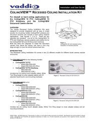
Image: EZIM <strong>CCU</strong> Top Panel (left to right) <strong>and</strong> ISO View of EZIM <strong>CCU</strong><br />
POWER RJ-45: The EZIM <strong>CCU</strong> receives 36 VDC on one Cat-5<br />
cable (all 4-pair) from the <strong>CCU</strong>.<br />
Be sure to mark the Power Cat-5 <strong>and</strong> avoid plugging it<br />
into a place it doesn’t belong.<br />
G/L Gain Potentiometer: Adjust this level control to the level<br />
that works with the system. This control exists to compensate for<br />
the length of the cable used.<br />
EZIM <strong>CCU</strong>:<br />
Top Connector Panel <strong>and</strong><br />
25-pin side connector shown<br />
RS-232 IN / G/L IN RJ-45: Connect this RJ-45 with a Cat-5 cable to the RS-232 OUT / G/L OUT RJ-45 on the<br />
back of the <strong>CCU</strong>.<br />
Video RJ-45: This RJ-45 sends the camera’s four (4) video signals on 4-pr (differential video) from the EZIM<br />
<strong>CCU</strong> to the Quick-Connect <strong>CCU</strong> on Cat-5 cable.<br />
Installation:<br />
Installation Basics:<br />
The WallVIEW <strong>CCU</strong> system was specifically designed for installation on a vertical wall surface with Cat-5 cable<br />
connectivity for Video, Power <strong>and</strong> Control signaling (three Cat-5 cables are required). Installation is simplified in<br />
that no custom 8-Pin mini-din cables or expensive plenum coax cables are needed <strong>and</strong> no power outlets are<br />
required near the camera bracket. All cabling is routed to the head-end using Cat-5 cables using st<strong>and</strong>ard<br />
straight through RJ-45 connectors (568B termination). “Pass-thru” type RJ-45 connectors should never be used.<br />
Before Installing:<br />
Locate the camera mounting location paying close attention to camera viewing angles, lighting conditions,<br />
possible line of site obstructions, <strong>and</strong> checking for in-wall obstructions where the camera is to be mounted.<br />
Pick a mounting location that will optimize the performance of the camera.<br />
Pre-wire all cabling as required, test <strong>and</strong> mark the cables POWER, VIDEO <strong>and</strong> CONTROL. Do<br />
not guess at the cable’s function <strong>and</strong> try the “process of elimination method” <strong>and</strong> plug the<br />
POWER cable into all the RJ-45 jacks to see which one cable powers the camera. In all<br />
likelihood, this method will cause damage to your system <strong>and</strong> your warranty will be voided.<br />
© 2012 <strong>Vaddio</strong> - All Rights Reserved. Document Number <strong>342</strong>-<strong>0498</strong> Rev A Page 7 of 16