You also want an ePaper? Increase the reach of your titles
YUMPU automatically turns print PDFs into web optimized ePapers that Google loves.
Quick Connect <strong>CCU</strong> <strong>Kit</strong> <strong>and</strong> WallVIEW <strong>Kit</strong> for the AW-HE120<br />
Shift to Bottom Row Controls:<br />
Red <strong>and</strong> Blue Pedestal: These controls allow the Red <strong>and</strong> Blue Pedestal to be adjusted (see Panasonic<br />
manual).<br />
DRS: Dynamic Range Stretch optimizes images that have a wide contrast range. When dark, bright <strong>and</strong><br />
intermediate areas are all in the same image or rapidly changing lighting changes occur frequently, DRS<br />
estimates a gamma curve <strong>and</strong> knee slope for each image pixel to minimize blocked shadows <strong>and</strong> blown<br />
highlights. Set to off to disable the DRS feature.<br />
Shutter: Choose between settings: 1/100, 1/250. 1/500, 1/1000, 1/2000, 1/4000, 1/10,000 <strong>and</strong> Syncroserve.<br />
ND Filter: This is for selecting the transmissivity of the ND filter (light-dimming filter), which is incorporated in the<br />
lens. Four positions (Off, 1/4, 1/16. 1/64).<br />
The menus <strong>and</strong> controllability of the AW-HE120 is rather extensive, so please see the Panasonic manual for<br />
further explanation of the control parameters.<br />
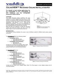
Image: Rear Panel Connections <strong>and</strong> Controls (left to right)<br />
Power Supply Input: The Quick-Connect <strong>CCU</strong> uses a 36VDC, 2.78 Amp power supply on a 5.5mm OD x<br />
2.5mm ID connector.<br />
Power on RJ-45: Power is provided on a Cat-5 cable to EZIM <strong>CCU</strong> (EZCamera Interface Module).<br />
RS-232 IN on RJ-45: RS-232 Input from ProductionVIEW, Precision Camera Controller or PTZ controller.<br />
Daisy Chain control is not supported.<br />
RS-232 OUT / G/L Out on RJ-45: RS-232 <strong>and</strong> G/L outputs on Cat-5 provide control <strong>and</strong> sync to the EZIM <strong>CCU</strong>.<br />
NOTE: See Appendix 1 for information on adjusting Genlock Gain on the EZIM <strong>CCU</strong>.<br />
Tally on 2-pin Molex 5.0mm Euro-Style connector: A contact closure lights the blue LED on front panel<br />
allowing indication of which <strong>CCU</strong> <strong>and</strong> camera combination is active in a multi-camera <strong>CCU</strong> installation. A tally<br />
comm<strong>and</strong> will also be sent to the camera via RS-232 to illuminate the LED on the cameras that have on-board<br />
tally lights (<strong>Vaddio</strong> <strong>and</strong> BRC Series cameras).<br />
G/L Input on BNC-F: For use with black burst generators to externally sync the cameras. This input is<br />
transmitted through a differential amplifier to a receiver at the EZIM <strong>CCU</strong>. The G/L gain adjustment is on the<br />
EZIM <strong>CCU</strong> or the receive side of the signal.<br />
Camera Feature Switches: The <strong>CCU</strong> interface has an 8-position dip switch on the rear panel to allow future<br />
functionality. All switches should be in the down position.<br />
Y-Gain: Adjusts Y-Gain <strong>and</strong> allows the user to fine tune the video signal especially over longer cable lengths.<br />
Adjust to taste <strong>and</strong> system requirements.<br />
Distance: Distance Adjustments for Cat. 5 cable (