
Create successful ePaper yourself
Turn your PDF publications into a flip-book with our unique Google optimized e-Paper software.
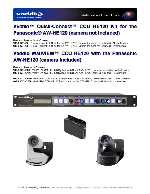
Installation <strong>and</strong> User Guide<br />
VADDIO Quick-Connect <strong>CCU</strong> HE120 <strong>Kit</strong> for the<br />
Panasonic® AW-HE120 (camera not included)<br />
Part Numbers without Camera:<br />
998-6127-000: Quick-Connect <strong>CCU</strong> <strong>Kit</strong> for the AW-HE120 Camera (camera not included) - North America<br />
998-6127-000: Quick-Connect <strong>CCU</strong> <strong>Kit</strong> for the AW-HE120 Camera (camera not included) - International<br />
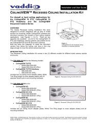
<strong>Vaddio</strong> WallVIEW <strong>CCU</strong> HE120 with the Panasonic<br />
AW-HE120 (camera included)<br />
Part Numbers with Camera:<br />
999-6127-000K: WallVIEW <strong>CCU</strong> HE120 System with Black AW-HE120 (camera included) - North America<br />
999-6127-001K: WallVIEW <strong>CCU</strong> HE120 System with Black AW-HE120 (camera included) - International<br />
999-6127-000W: WallVIEW <strong>CCU</strong> HE120 System with White AW-HE120 (camera included) - North America<br />
999-6127-001W: WallVIEW <strong>CCU</strong> HE120 System with White AW-HE120 (camera included) - International<br />
© 2012 <strong>Vaddio</strong> - All Rights Reserved. Specifications are subject to change without prior notice. Document Number <strong>342</strong>-<strong>0498</strong> Rev A
Quick Connect <strong>CCU</strong> <strong>Kit</strong> <strong>and</strong> WallVIEW <strong>Kit</strong> for the AW-HE120<br />
Table of Contents<br />
Overview: ................................................................................................................................................................... 3<br />
Figure: Front Panel of the Quick-Connect <strong>CCU</strong> for the AW-HE120 Camera ................................................... 3<br />
Important Safeguards: ........................................................................................................................................... 3<br />
Intended Use .......................................................................................................................................................... 3<br />
Save These Instructions ........................................................................................................................................ 3<br />
Information: ............................................................................................................................................................ 4<br />
Unpacking: ................................................................................................................................................................. 4<br />
998-6127-000: Quick-Connect <strong>CCU</strong> <strong>Kit</strong> (NO CAMERA) for the AW-HE120 Camera - North America ................ 4<br />
998-6127-001: Quick-Connect <strong>CCU</strong> <strong>Kit</strong> (NO CAMERA) for the AW-HE120 Camera - International ................... 4<br />
999-6127-000K: WallVIEW <strong>CCU</strong> HE120 System - Black Camera - North America ............................................. 4<br />
999-6127-001K: WallVIEW <strong>CCU</strong> HE120 System - Black Camera - International ................................................ 4<br />
999-6127-000W: WallVIEW <strong>CCU</strong> HE120 System - White Camera - North America ........................................... 4<br />
999-6127-001W: WallVIEW <strong>CCU</strong> HE120 System - White Camera - International .............................................. 4<br />
Anatomy of the <strong>CCU</strong> Controlled Camera System ..................................................................................................... 5<br />
Image: The Quick-Connect <strong>CCU</strong> Front Panel Controls (left to right) ................................................................ 5<br />
Image: Magnification of Control Buttons <strong>and</strong> Rotary Encoders (from left to right) ............................................ 5<br />
Image: Rear Panel Connections <strong>and</strong> Controls (left to right) ............................................................................. 6<br />
Image: EZIM <strong>CCU</strong> Top Panel (left to right) <strong>and</strong> ISO View of EZIM <strong>CCU</strong> .......................................................... 7<br />
Installation: ................................................................................................................................................................. 7<br />
Installation Basics: ................................................................................................................................................. 7<br />
Step By Step Mounting Instructions: ...................................................................................................................... 8<br />
Image: Heavy duty wall mount .......................................................................................................................... 8<br />
Image: Heavy Duty Wall Mount ......................................................................................................................... 8<br />
Drawing: High Definition Break Out Cable ........................................................................................................ 8<br />
Completing the Installation: .................................................................................................................................... 9<br />
Drawing: Basic System Connectivity ............................................................................................................... 10<br />
Optimizing System Performance: ............................................................................................................................ 10<br />
General Specifications ............................................................................................................................................. 11<br />
Warranty Information: .............................................................................................................................................. 12<br />
Compliance <strong>and</strong> CE Declaration of Conformity - Quick-Connect <strong>CCU</strong> <strong>and</strong> EZIM <strong>CCU</strong> ...................................... 13<br />
Appendix 1: Cable Pin-outs for the Quick-Connect <strong>CCU</strong> System .......................................................................... 14<br />
© 2012 <strong>Vaddio</strong> - All Rights Reserved. Document Number <strong>342</strong>-<strong>0498</strong> Rev A Page 2 of 16
Quick Connect <strong>CCU</strong> <strong>Kit</strong> <strong>and</strong> WallVIEW <strong>Kit</strong> for the AW-HE120<br />
Overview:<br />
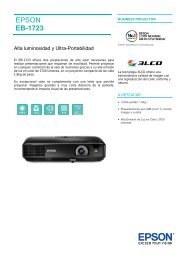
The <strong>Vaddio</strong> Quick-Connect <strong>CCU</strong> system for the AW-HE120 camera allows the user to control<br />
the color output of the camera’s image sensor through both Red <strong>and</strong> Blue Gain controls, Detail,<br />
Chroma, Gamma, Total Pedestal, as well as Iris <strong>and</strong> Gain levels, to provide a higher quality<br />
image. In addition, there are also Red <strong>and</strong> Blue Pedestal parameters. In addition, there are<br />
also Pedestal, Gamma <strong>and</strong> Chroma adjustments for added fine-tuning of the camera’s image.<br />
Figure: Front Panel of the Quick-Connect <strong>CCU</strong> for the AW-HE120 Camera<br />
The Panasonic AW-HE120 uses st<strong>and</strong>ard RS-422 control protocol. To be 100% compatible with <strong>Vaddio</strong><br />
equipment, everything is included to convert <strong>Vaddio</strong>’s RS-232 to RS-422. This allows for the operation with the<br />
complete line of <strong>Vaddio</strong> ProductionVIEW consoles (Precision Camera Controller, ProductionVIEW HD,<br />
ProductionVIEW HD MV <strong>and</strong> the ProductionVIEW HD-SDI MV with integrated multi-viewers.<br />
The <strong>CCU</strong> has many features, including Tally illumination on the front panel <strong>and</strong> on the on the camera which<br />
allows the presenter to know which camera is live <strong>and</strong> what <strong>CCU</strong> to adjust if a tweak is needed. Genlock is<br />
delivered to the camera over Cat-5 with a level adjustment on the EZIM <strong>CCU</strong>. The ability to store settings on two<br />
discrete Scene buttons is included, <strong>and</strong> buttons for Auto White Balance, One Push White Balance <strong>and</strong> Auto Iris<br />
programming are also available.<br />
The AW-HE120 HD PTZ Camera features a 20x zoom lens <strong>and</strong> a three (3), 1/3-type 2.2 megapixel CMOS imager<br />
sensors. The systems are available as a WallVIEW <strong>CCU</strong> HE120 System with the camera included, or as a Quick-<br />
Connect <strong>CCU</strong> <strong>Kit</strong>, without the camera. The Quick-Connect <strong>CCU</strong> for the AW-HE120 has the ability to produce<br />
remarkable video in a wide range of shooting conditions<br />
Important Safeguards:<br />
Read <strong>and</strong> underst<strong>and</strong> all instructions <strong>and</strong> warranty statements before using. Do not operate any device if it has<br />
been dropped or damaged. In this case, a <strong>Vaddio</strong> technician must examine the product before operating. To<br />
reduce the risk of electric shock, do not immerse in water or other liquids <strong>and</strong> avoid extremely humid conditions.<br />
General Safeguard: Use only the power supply provided with the system. Use of any<br />
unauthorized power supply will void any <strong>and</strong> all warranties. Please do not cut the<br />
secondary side (or the DC side) of the power supply <strong>and</strong> attempt to extend the power to the<br />
camera. The warranty is voided when the cable is cut.<br />
Please do not use “pass-thru” type RJ-45 connectors. These pass-thru type connectors do not<br />
work well for professional installations <strong>and</strong> can be the cause of intermittent connections which,<br />
can result in the RS-232 control line failing <strong>and</strong> locking up, <strong>and</strong>/or compromising the HSDS<br />
signals. For best results please use st<strong>and</strong>ard RJ-45 connectors <strong>and</strong> test all cables for proper pinouts<br />
prior to use <strong>and</strong> connection to <strong>Vaddio</strong> product.<br />
Intended Use<br />
Before operating the device, please read the entire manual thoroughly. The system was designed, built <strong>and</strong><br />
tested for use indoors, <strong>and</strong> with the provided power supply <strong>and</strong> cabling. The use of a power supply other than the<br />
one provided or outdoor operation has not been tested <strong>and</strong> could damage the device <strong>and</strong>/or create a potentially<br />
unsafe operating condition.<br />
Save These Instructions<br />
The information contained in this manual will help you install <strong>and</strong> operate your product. If these instructions are<br />
misplaced, <strong>Vaddio</strong> keeps copies of Specifications, Installation <strong>and</strong> User Guides <strong>and</strong> most pertinent product<br />
drawings for the <strong>Vaddio</strong> product line on the <strong>Vaddio</strong> website. These documents can be downloaded from<br />
www.vaddio.com free of charge.<br />
© 2012 <strong>Vaddio</strong> - All Rights Reserved. Document Number <strong>342</strong>-<strong>0498</strong> Rev A Page 3 of 16
Quick Connect <strong>CCU</strong> <strong>Kit</strong> <strong>and</strong> WallVIEW <strong>Kit</strong> for the AW-HE120<br />
Information:<br />
For RS-232 control information, please see the full-length Technical Manual for the Panasonic AW-HE120. This<br />
manual can be found either on the Panasonic or the <strong>Vaddio</strong> website.<br />
Unpacking:<br />
Carefully remove the device(s) <strong>and</strong> all parts from the packaging. Please do not toss the packaging yet, just set it aside where<br />
it won’t be in the way. Unpack <strong>and</strong> identify the following parts:<br />
998-6127-000: Quick-Connect <strong>CCU</strong> <strong>Kit</strong> (NO CAMERA) for the AW-HE120 Camera - North America<br />
Quick-Connect <strong>CCU</strong> (P/N: 998-1105-032) for the AW-HE120<br />
One(1) 2-pin Molex 5.0mm Euro-style connector for the Tally Input<br />
One (1) 36 VDC Switching power supply with power cord for North America<br />
One (1) EZIM <strong>CCU</strong> (998-6700-002)<br />
Two (2) 6-32 x .188” Pan Head for attaching EZIM to the Wall Mount<br />
One (1) HD Break-out Cable for EZIM <strong>CCU</strong> to Camera (not shown)<br />
One (1) DE-9F to RJ-45F, RS-232 to RS-422 Adapter (998-1005-232)<br />
One (1) CommFront CVT-485_422-1 RS-232 to RS-422 Converter<br />
One (1) 1’ Cat 5 Patch Cable<br />
One (1) Heavy Duty, Gusseted Wall Mount 535-2000-223<br />
Four (4) 800-616, #8 x 1.25” Sheet Metal Screws<br />
Four (4) 800-617, Wall Anchors (EZ Anchors)<br />
Two (2) 85033, ¼” x 20 x 0.5” Pan Head Screws<br />
Documentation<br />
998-6127-001: Quick-Connect <strong>CCU</strong> <strong>Kit</strong> (NO CAMERA) for the AW-HE120 Camera - International<br />
One (1) Quick-Connect <strong>CCU</strong> (P/N: 998-1105-032) for the AW-HE120<br />
One(1) 2-pin Molex 5.0mm Euro-style connector for the Tally Input<br />
One (1) 36 VDC Switching power supply<br />
One (1) Euro Power Cord<br />
One (1) UK Power Cord<br />
One (1) EZIM <strong>CCU</strong> (998-6700-002)<br />
Two (2) 6-32 x .188” Pan Head for attaching EZIM to the Wall Mount<br />
One (1) HD Break-out Cable for EZIM <strong>CCU</strong> to Camera (not shown)<br />
One (1) DE-9F to RJ-45F, RS-232 to RS-422 Adapter (998-1005-232)<br />
One (1) CommFront CVT-485_422-1 RS-232 to RS-422 Converter<br />
One (1) 1’ Cat 5 Patch Cable<br />
One (1) Heavy Duty, Gusseted Wall Mount 535-2000-223<br />
Four (4) #8 x 1.25” Sheet Metal Screws<br />
Four (4) Wall Anchors (EZ Anchors)<br />
Two (2) ¼” x 20 x 0.5” Pan Head Screws<br />
Documentation<br />
999-6127-000K: WallVIEW <strong>CCU</strong> HE120 System - Black Camera - North America<br />
One (1) 998-6217-000 Quick-Connect <strong>CCU</strong> <strong>Kit</strong> Complete as Listed Above for the AW-HE120<br />
One (1) Panasonic AW-HE120K Black Camera Complete with manual <strong>and</strong> accessories by Panasonic<br />
999-6127-001K: WallVIEW <strong>CCU</strong> HE120 System - Black Camera - International<br />
One (1) 998-6217-001 Quick-Connect <strong>CCU</strong> <strong>Kit</strong> Complete as Listed Above for the AW-HE120<br />
One (1) Panasonic AW-HE120K Black Camera Complete with manual <strong>and</strong> accessories by Panasonic<br />
999-6127-000W: WallVIEW <strong>CCU</strong> HE120 System - White Camera - North America<br />
One (1) 998-6217-000 Quick-Connect <strong>CCU</strong> <strong>Kit</strong> Complete as Listed Above for the AW-HE120<br />
One (1) Panasonic AW-HE120W White Camera Complete with manual <strong>and</strong> accessories by Panasonic<br />
999-6127-001W: WallVIEW <strong>CCU</strong> HE120 System - White Camera - International<br />
One (1) 998-6217-001 Quick-Connect <strong>CCU</strong> <strong>Kit</strong> Complete as Listed Above for the AW-HE120<br />
One (1) Panasonic AW-HE120W White Camera Complete with manual <strong>and</strong> accessories by Panasonic<br />
© 2012 <strong>Vaddio</strong> - All Rights Reserved. Document Number <strong>342</strong>-<strong>0498</strong> Rev A Page 4 of 16
Quick Connect <strong>CCU</strong> <strong>Kit</strong> <strong>and</strong> WallVIEW <strong>Kit</strong> for the AW-HE120<br />
Anatomy of the <strong>CCU</strong> Controlled Camera System<br />
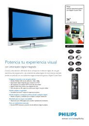
Image: The Quick-Connect <strong>CCU</strong> Front Panel Controls (left to right)<br />
Tally Light: The blue LED tally light on the front panel is tied to the tally contacts on the rear panel allowing the<br />
user to easily track which camera interface is being used in a multi-camera system by supplying a simple contact<br />
closure (i.e. from ProductionVIEW Super Joystick or ProductionVIEW HD).<br />
LCD Display: Backlit (blue) display indicates which mode is active (<strong>CCU</strong> CONTROL or PTZ CONTROL). In<br />
<strong>CCU</strong> CONTROL mode, when a rotary encoder is touched, the name of the control being actuated <strong>and</strong> the value<br />
of that assigned parameter will be displayed.<br />
Image: Magnification of Control Buttons <strong>and</strong> Rotary Encoders (from left to right)<br />
<strong>CCU</strong> Control Switch: Backlit (blue) SPDT switch, lit when activated, blocks the incoming PTZ controls on the<br />
RS-232 input <strong>and</strong> allows the end user to make adjustments to the camera image characteristics. When off or<br />
deactivated, PTZ information is passed to the camera <strong>and</strong> the front panel controls are deactivated to avoid<br />
latency.<br />
Scene A <strong>and</strong> B: Two camera adjustment scenes (A & B) can be stored into microprocessor memory. When lit<br />
(backlit blue SPDT switch), the scene is activated. To store a scene, the user adjusts the controls <strong>and</strong> touches<br />
<strong>and</strong> holds the scene button down until the button blinks.<br />
Detail: The Detail control sharpens or softens objects in the frame.<br />
Red & Blue Gain: The Red <strong>and</strong> Blue Gain encoders adjust the red <strong>and</strong> blue gain of the signal when AWB is<br />
disengaged.<br />
Shift/WB Set: Shift on mode allows features that are below the <strong>CCU</strong> knob. Shift off mode allows features listed<br />
above the <strong>CCU</strong> knob.<br />
The White Balance controls/adjusts the color levels automatically when engaged. Turn off AWB to manually<br />
adjust the Red <strong>and</strong> Blue gain.<br />
WB Mode: Toggles between white balance modes AWB A, AWB B, ATW, 3200K, 5600K. AWB A or AWB B<br />
must be engaged to manually adjust the Red <strong>and</strong> Blue controls. See Panasonic manual.<br />
Pedestal: Controls the absolute black level of an image.<br />
Chroma: Controls 7 levels of variability of the overall color of the image being captured.<br />
Gamma: Adjusts the overall brightness of an image.<br />
Auto Iris: The Auto Iris mode automatically adjusts the iris <strong>and</strong> gain of the camera. To manually adjust the iris<br />
or gain, turn off this control.<br />
Manual Iris: The manual iris control allows the user to set the iris manual to one of the 18 settings available.<br />
Gain: The Gain control boosts the signal level when the iris is open all the way, <strong>and</strong> there is not enough lighting<br />
available. To manually adjust the gain Auto Iris must be off.<br />
© 2012 <strong>Vaddio</strong> - All Rights Reserved. Document Number <strong>342</strong>-<strong>0498</strong> Rev A Page 5 of 16
Quick Connect <strong>CCU</strong> <strong>Kit</strong> <strong>and</strong> WallVIEW <strong>Kit</strong> for the AW-HE120<br />
Shift to Bottom Row Controls:<br />
Red <strong>and</strong> Blue Pedestal: These controls allow the Red <strong>and</strong> Blue Pedestal to be adjusted (see Panasonic<br />
manual).<br />
DRS: Dynamic Range Stretch optimizes images that have a wide contrast range. When dark, bright <strong>and</strong><br />
intermediate areas are all in the same image or rapidly changing lighting changes occur frequently, DRS<br />
estimates a gamma curve <strong>and</strong> knee slope for each image pixel to minimize blocked shadows <strong>and</strong> blown<br />
highlights. Set to off to disable the DRS feature.<br />
Shutter: Choose between settings: 1/100, 1/250. 1/500, 1/1000, 1/2000, 1/4000, 1/10,000 <strong>and</strong> Syncroserve.<br />
ND Filter: This is for selecting the transmissivity of the ND filter (light-dimming filter), which is incorporated in the<br />
lens. Four positions (Off, 1/4, 1/16. 1/64).<br />
The menus <strong>and</strong> controllability of the AW-HE120 is rather extensive, so please see the Panasonic manual for<br />
further explanation of the control parameters.<br />
Image: Rear Panel Connections <strong>and</strong> Controls (left to right)<br />
Power Supply Input: The Quick-Connect <strong>CCU</strong> uses a 36VDC, 2.78 Amp power supply on a 5.5mm OD x<br />
2.5mm ID connector.<br />
Power on RJ-45: Power is provided on a Cat-5 cable to EZIM <strong>CCU</strong> (EZCamera Interface Module).<br />
RS-232 IN on RJ-45: RS-232 Input from ProductionVIEW, Precision Camera Controller or PTZ controller.<br />
Daisy Chain control is not supported.<br />
RS-232 OUT / G/L Out on RJ-45: RS-232 <strong>and</strong> G/L outputs on Cat-5 provide control <strong>and</strong> sync to the EZIM <strong>CCU</strong>.<br />
NOTE: See Appendix 1 for information on adjusting Genlock Gain on the EZIM <strong>CCU</strong>.<br />
Tally on 2-pin Molex 5.0mm Euro-Style connector: A contact closure lights the blue LED on front panel<br />
allowing indication of which <strong>CCU</strong> <strong>and</strong> camera combination is active in a multi-camera <strong>CCU</strong> installation. A tally<br />
comm<strong>and</strong> will also be sent to the camera via RS-232 to illuminate the LED on the cameras that have on-board<br />
tally lights (<strong>Vaddio</strong> <strong>and</strong> BRC Series cameras).<br />
G/L Input on BNC-F: For use with black burst generators to externally sync the cameras. This input is<br />
transmitted through a differential amplifier to a receiver at the EZIM <strong>CCU</strong>. The G/L gain adjustment is on the<br />
EZIM <strong>CCU</strong> or the receive side of the signal.<br />
Camera Feature Switches: The <strong>CCU</strong> interface has an 8-position dip switch on the rear panel to allow future<br />
functionality. All switches should be in the down position.<br />
Y-Gain: Adjusts Y-Gain <strong>and</strong> allows the user to fine tune the video signal especially over longer cable lengths.<br />
Adjust to taste <strong>and</strong> system requirements.<br />
Distance: Distance Adjustments for Cat. 5 cable (
Quick Connect <strong>CCU</strong> <strong>Kit</strong> <strong>and</strong> WallVIEW <strong>Kit</strong> for the AW-HE120<br />
Connector Labels <strong>and</strong> Supported Video Signals<br />
Y/Y:<br />
Y of YPbPr - or - Y (luminance) of Y/C on BNC-F connector<br />
PB/C: PB of YPbPr - or - C (chrominance) of Y/C on BNC-F connector<br />
PR:<br />
PR of YPbPr only on BNC-F connector<br />
COMP: Composite (CVBS) Video on BNC-F connector<br />
Video RJ-45: This RJ-45 receives the camera’s four (4) differential video signals from the EZIM <strong>CCU</strong> to the<br />
Quick-Connect <strong>CCU</strong> on Video Cat-5 cable.<br />
Image: EZIM <strong>CCU</strong> Top Panel (left to right) <strong>and</strong> ISO View of EZIM <strong>CCU</strong><br />
POWER RJ-45: The EZIM <strong>CCU</strong> receives 36 VDC on one Cat-5<br />
cable (all 4-pair) from the <strong>CCU</strong>.<br />
Be sure to mark the Power Cat-5 <strong>and</strong> avoid plugging it<br />
into a place it doesn’t belong.<br />
G/L Gain Potentiometer: Adjust this level control to the level<br />
that works with the system. This control exists to compensate for<br />
the length of the cable used.<br />
EZIM <strong>CCU</strong>:<br />
Top Connector Panel <strong>and</strong><br />
25-pin side connector shown<br />
RS-232 IN / G/L IN RJ-45: Connect this RJ-45 with a Cat-5 cable to the RS-232 OUT / G/L OUT RJ-45 on the<br />
back of the <strong>CCU</strong>.<br />
Video RJ-45: This RJ-45 sends the camera’s four (4) video signals on 4-pr (differential video) from the EZIM<br />
<strong>CCU</strong> to the Quick-Connect <strong>CCU</strong> on Cat-5 cable.<br />
Installation:<br />
Installation Basics:<br />
The WallVIEW <strong>CCU</strong> system was specifically designed for installation on a vertical wall surface with Cat-5 cable<br />
connectivity for Video, Power <strong>and</strong> Control signaling (three Cat-5 cables are required). Installation is simplified in<br />
that no custom 8-Pin mini-din cables or expensive plenum coax cables are needed <strong>and</strong> no power outlets are<br />
required near the camera bracket. All cabling is routed to the head-end using Cat-5 cables using st<strong>and</strong>ard<br />
straight through RJ-45 connectors (568B termination). “Pass-thru” type RJ-45 connectors should never be used.<br />
Before Installing:<br />
Locate the camera mounting location paying close attention to camera viewing angles, lighting conditions,<br />
possible line of site obstructions, <strong>and</strong> checking for in-wall obstructions where the camera is to be mounted.<br />
Pick a mounting location that will optimize the performance of the camera.<br />
Pre-wire all cabling as required, test <strong>and</strong> mark the cables POWER, VIDEO <strong>and</strong> CONTROL. Do<br />
not guess at the cable’s function <strong>and</strong> try the “process of elimination method” <strong>and</strong> plug the<br />
POWER cable into all the RJ-45 jacks to see which one cable powers the camera. In all<br />
likelihood, this method will cause damage to your system <strong>and</strong> your warranty will be voided.<br />
© 2012 <strong>Vaddio</strong> - All Rights Reserved. Document Number <strong>342</strong>-<strong>0498</strong> Rev A Page 7 of 16
Quick Connect <strong>CCU</strong> <strong>Kit</strong> <strong>and</strong> WallVIEW <strong>Kit</strong> for the AW-HE120<br />
Please do not use “pass-thru” type RJ-45 connectors. The <strong>Vaddio</strong> Cat-5 wiring st<strong>and</strong>ard uses<br />
pins 7 <strong>and</strong> 8 on both the video <strong>and</strong> the control Cat-5e cables. The pass-through connectors have<br />
proven to provide insufficient connectivity for these important signals. They are “ok” for voice <strong>and</strong><br />
data, but not for video <strong>and</strong> control.<br />
Step By Step Mounting Instructions:<br />
Step 1:<br />
After determining the optimum location of the camera system, mark locations for the four screw holes <strong>and</strong> cable<br />
pass-thru (vertical oval). Install the drywall mounts <strong>and</strong> cut the hole for the cable pass-thru. At this point, do not<br />
install the Wall Mount.<br />
Image: Heavy duty wall mount<br />
The wall mount may be mounted directly to a 3-gang wall box or to drywall<br />
with the appropriate wall anchors.<br />
Step 2:<br />
Connect the break out cable to the EZIM <strong>CCU</strong>. Mount the EZIM <strong>CCU</strong> <strong>and</strong> break out cable in the back of the wall<br />
mount, using the supplied screws <strong>and</strong> two tapped screw holes.<br />
Image: Heavy Duty Wall Mount<br />
Wall mount shown with EZIM <strong>CCU</strong> <strong>and</strong> HD break out cable attached to<br />
the back of the mount.<br />
Drawing: High Definition Break Out Cable<br />
Exact Cable<br />
Not Shown<br />
DB-25-M<br />
plugs into<br />
EZIM <strong>CCU</strong><br />
12 VDC Power on<br />
3mm ID Connector<br />
CVBS on<br />
BNC-M<br />
G/L on<br />
BNC-M<br />
YPbPr on<br />
DE-15-M<br />
RS-232 to RS-<br />
422 converter<br />
<strong>and</strong> adapter<br />
© 2012 <strong>Vaddio</strong> - All Rights Reserved. Document Number <strong>342</strong>-<strong>0498</strong> Rev A Page 8 of 16
Quick Connect <strong>CCU</strong> <strong>Kit</strong> <strong>and</strong> WallVIEW <strong>Kit</strong> for the AW-HE120<br />
Step 3:<br />
Take the Wall Mount, with the EZIM <strong>CCU</strong> <strong>and</strong> break out cable installed, <strong>and</strong> place it against the drywall anchors<br />
or 3-gang wall box, making sure to pull the three Cat-5 cables through the oval pass-through hole. Finger-tighten<br />
the screws to the mount <strong>and</strong> confirm that the base is level. Tighten the screws firmly. If the bracket is to be<br />
mounted on a 3-gang wall box, use the screws supplied with the electrical box.<br />
Step 4:<br />
Confirm that the Cat-5 cables are terminated correctly, by testing them with a continuity tester. Connect the<br />
break out cables to the appropriate ports on the AW-HE120. The break out cable for the HE 100 has an RS-232<br />
to RS-422 adapter in-line, with a 1 ft. CAT-5 cable, which connects to the Controller port on the back of the<br />
camera. Push the camera into place <strong>and</strong> dress the cables. Secure the camera to the mount <strong>and</strong> using the ¼”-20<br />
screws.<br />
Step 5:<br />
The Quick-Connect <strong>CCU</strong> interface has an 8-position dip switch on the rear panel (see page 4). Set Dip Switch 2<br />
to the UP position. All other switches should be in the DOWN position.<br />
Description Dip Switch (Up = ON) 1 2 3 4 5 6 7 8<br />
Panasonic AW-HE120<br />
UP<br />
Setting the #2 dip switch to the UP position allows<br />
<strong>Vaddio</strong>’s ProductionVIEW controllers <strong>and</strong> switchers to<br />
recognize the camera.<br />
D<br />
N<br />
D<br />
N<br />
D<br />
N<br />
D<br />
N<br />
D<br />
N<br />
D<br />
N<br />
D<br />
N<br />
Step 6:<br />
The Quick-Connect <strong>CCU</strong> is a 1-RU rack mount interface that breaks out the signals from the Cat. 5 cables back<br />
to the st<strong>and</strong>ard connectors. Connect the other side of the appropriate Cat-5 cable to the <strong>CCU</strong> except for power.<br />
Note: Plugging the POWER CAT-5 Cable into the wrong RJ-45 may cause damage to the camera system <strong>and</strong> void the<br />
warranty.<br />
Completing the Installation:<br />
Connect the Power Cat-5 cable to the <strong>CCU</strong> <strong>and</strong> connect the <strong>Vaddio</strong> 36 VDC power supply to an AC outlet.<br />
Power will travel down the Power Cat-5 cable to the EZIM <strong>CCU</strong>, powering the camera. The camera will “Home”<br />
to a centered position ready for control information from the IR Remote or camera controller. To insure proper<br />
continuity of control <strong>and</strong> operation of the cameras, the RS-232 controller (control system or joystick) must be<br />
powered on after the camera. Move the camera <strong>and</strong> test the video.<br />
Setting the AW-HE120 Video Format <strong>and</strong> Output Settings:<br />
With the IR Remote Control, enter the camera’s menu system <strong>and</strong> set the camera’s Picture Format, which ranges<br />
from 480/29.97psF to 1080/30p.<br />
NOTE: Not all of the resolution options on the AW-HE120 will be recognized by the receiving<br />
device (ProductionVIEW HD or HD video monitor, etc.), so be sure to select an appropriate<br />
resolution for your external device that is connected to the Quick-Connect <strong>CCU</strong>.<br />
Setting the Camera Output Mode:<br />
The modes are RGB, YPbPr <strong>and</strong> Y/C Use only YPbPr with the Quick-Connect <strong>CCU</strong>.<br />
Connecting the Tally Port (optional)<br />
The <strong>CCU</strong> system is capable of illuminating a Tally light on the front of the Quick-Connect enclosure. This light<br />
provides a visual indicator to the equipment operator to know which camera is live during a broadcast. In<br />
addition the tally function will illuminate the tally light on the front of the camera lens, to allow the presenter to<br />
know which camera is live.<br />
The basic system connectivity is illustrated on the next page.<br />
© 2012 <strong>Vaddio</strong> - All Rights Reserved. Document Number <strong>342</strong>-<strong>0498</strong> Rev A Page 9 of 16
Quick Connect <strong>CCU</strong> <strong>Kit</strong> <strong>and</strong> WallVIEW <strong>Kit</strong> for the AW-HE120<br />
Drawing: Basic System Connectivity<br />
Wiring Diagram Example:<br />
System Configuration Notes:<br />
The Quick-Connect <strong>CCU</strong> System uses a Cat-5 (all 4-pairs) for power to ensure the motors receive the required current to operate properly.<br />
The Video Cat-5 cable uses all four pairs for video (YPbPr & CVBS). The RS-232 Cat-5 provides communication to the camera for <strong>CCU</strong>, PTZ<br />
control <strong>and</strong> G/L (where applicable) to the camera. These Cat. 5 cables can be run up to 500’ (152.4m). See Appendix 1 for wiring <strong>and</strong> pinout<br />
information.<br />
EZIM <strong>CCU</strong> Top Panel<br />
HD Break-out<br />
Cable<br />
Power<br />
RS- 232 to<br />
RS-422<br />
Converter<br />
RS-422<br />
on 1 ft.<br />
Cat.-5<br />
CVBS<br />
G/L<br />
DB-9 F<br />
to Cat 5<br />
Power<br />
Cat-5 Cables<br />
up to 500’<br />
HD-YPbPr Out<br />
AW-HE120 Camera, Wall Mount<br />
with EZIM <strong>CCU</strong> (behind camera)<br />
Note: Camera not included<br />
RS-232 & G/L<br />
HSDS Video on Cat-5<br />
Quick-Connect <strong>CCU</strong><br />
+ G<br />
RS-232<br />
Tally<br />
G/L Box<br />
HD YPbPr<br />
Composite<br />
Video<br />
HD Video<br />
ProductionVIEW HD<br />
Simulated Video Feed<br />
Optimizing System Performance:<br />
Optimizing the <strong>CCU</strong> settings will help achieve maximum performance from the system. Difficult lighting is one of<br />
the most challenging problems video system integrators face. The <strong>Vaddio</strong> <strong>CCU</strong> will provide the flexibility to fine<br />
tune for variables such as cable length, day/night lighting transitions <strong>and</strong> lighting color temperature.<br />
<br />
<strong>CCU</strong> Control Mode: <strong>CCU</strong>’s that are sold with cameras other than <strong>Vaddio</strong> will have a <strong>CCU</strong> Control button<br />
with the scene controls. Make sure <strong>and</strong> select <strong>CCU</strong> Control if available prior to making <strong>CCU</strong> adjustments.<br />
PTZ control will not be available in this mode.<br />
© 2012 <strong>Vaddio</strong> - All Rights Reserved. Document Number <strong>342</strong>-<strong>0498</strong> Rev A Page 10 of 16
Quick Connect <strong>CCU</strong> <strong>Kit</strong> <strong>and</strong> WallVIEW <strong>Kit</strong> for the AW-HE120<br />
<br />
<br />
<br />
Adjust the Y Gain Settings*: Enable both Auto Iris <strong>and</strong> Auto White Balance prior to adjustment. Make sure<br />
the distance adjustment is set at its lowest setting. Adjust the trim pot on the back of the <strong>CCU</strong> counterclockwise<br />
until picture fades or drops out (cable length dependent). Adjust clockwise just past the setting<br />
where picture is restored. Leave the distance adjustment** at its lowest setting unless recommended by<br />
<strong>Vaddio</strong> technical support.<br />
Adjust Iris <strong>and</strong> Digital Gain Settings: Disable Auto Iris. Set the Iris to its largest aperture (lowest ‘f’<br />
number). Adjust the Gain until the image is too dark <strong>and</strong> then bring it back until it is properly exposed.<br />
Exposures that require high gain settings will have a grainy video image. Adjust the detail settings for a<br />
smoother image.<br />
Adjust Color to Taste: Required adjustments will vary based on the environment. The <strong>CCU</strong> allows the setup<br />
of several scenes so settings are available for a variety of conditions. Adjust the Chroma level to taste.<br />
Adjust Red/Blue levels next. Adjusting for skin tones or using a color chart is an easy way to find a good<br />
baseline setup.<br />
*Y Gain adjustment not active on <strong>CCU</strong> when using the SDI option<br />
**Distance adjustment not active on <strong>CCU</strong> when using the SDI option<br />
General Specifications<br />
Quick-Connect <strong>CCU</strong> HE120 (Please see specs for Panasonic camera in the Panasonic manual)<br />
Part Numbers<br />
998-6897-000: Quick-Connect <strong>CCU</strong> <strong>Kit</strong> for the BRC-H900 Camera (camera not included) - North America<br />
999-6897-001: Quick-Connect <strong>CCU</strong> <strong>Kit</strong> for the BRC-H900 Camera (camera not included) - International<br />
Quick-Connect <strong>CCU</strong> Interface<br />
Connectors<br />
Power Connector: 5.5mm OD x 2.5mm ID<br />
Power RJ-45: Supplies 36V to EZCamera Interface Module Regulator<br />
Control In RJ-45: Accepts RS-232 from ProductionVIEW or other non-daisy-chain control systems<br />
Control Out RJ-45: Passes RS-232 <strong>and</strong> Sync video feed to camera EZIM<br />
Tally: 2-Pin Phoenix type spring cage connector<br />
Video Inputs: BNC Connector for Sync<br />
Video Outputs: BNC Connectors for HD Analog Component (Y,PB,PR) / SD (Composite)<br />
Video RJ-45: Transports HD video from camera EZIM<br />
Camera Select Switch For Future Use – All switches should be in the down position<br />
Video Adjustments<br />
Y-Gain (luminance gain) for fine tuning over longer cable distances<br />
Distance Compensation: 100’, 200’, 300’, 400’+<br />
CAT-5 Cable Distance Up to 500’ (152.4m)<br />
Power Supply<br />
36 VDC, 2.78 Amp<br />
Dimensions<br />
1-RU Rack Mount - 1.75” H x 19” W x 6” D (4.45 cm x 4.26 cm x 15.24 cm)<br />
EZCamera Interface Module <strong>CCU</strong> (EZIM)<br />
Connectors<br />
Three (3) RJ-45 Connectors<br />
One DB-25 for Power, Video, Control & Genlock<br />
Cable Assembly<br />
DB-25M to DE-15, DE-9, BNC x 2, 3mm ID Power Connector<br />
Power Regulator<br />
Supplies 12VDC to Cameras<br />
Dimensions<br />
3” H x 4.5” W x 1.2” D (7.6 cm x 11.4 cm x 3 cm)<br />
Wall Mount H900 P/N: 535-2000-225<br />
Materials<br />
12-Gauge CRS with Black Powder Coat Paint<br />
Dimensions<br />
8” H x 8.5” W x 13.5” D (20.3 cm x 21.6 cm x 34.3 cm)<br />
Weight<br />
Approx. 6 lbs. (2.7kg)<br />
© 2012 <strong>Vaddio</strong> - All Rights Reserved. Document Number <strong>342</strong>-<strong>0498</strong> Rev A Page 11 of 16
Quick Connect <strong>CCU</strong> <strong>Kit</strong> <strong>and</strong> WallVIEW <strong>Kit</strong> for the AW-HE120<br />
Warranty Information:<br />
(See <strong>Vaddio</strong> Warranty, Service <strong>and</strong> Return Policies posted on vaddio.com for complete details):<br />
Hardware* Warranty: One year limited warranty on all parts. <strong>Vaddio</strong> warrants this product against defects in materials <strong>and</strong><br />
workmanship for a period of one year from the day of purchase from <strong>Vaddio</strong>. If <strong>Vaddio</strong> receives notice of such defects during<br />
the warranty period, they will, at their option, repair or replace products that prove to be defective. Please see <strong>Vaddio</strong>’s<br />
Service Terms <strong>and</strong> Conditions at vaddio.com for specific details <strong>and</strong> policies.<br />
Exclusions: The above warranty shall not apply to defects resulting from: improper or inadequate maintenance by the<br />
customer, customer applied software or interfacing, unauthorized modifications or misuse, operation outside the normal<br />
environmental specifications for the product, use of the incorrect power supply, improper installation (plugging things in<br />
wrong), improper extension of the power supply cable or improper site operation <strong>and</strong> maintenance.<br />
<strong>Vaddio</strong> Customer Service: <strong>Vaddio</strong> will test, repair, or replace the product or products without charge if the unit is under<br />
warranty <strong>and</strong> is found to be defective. If the product is out of warranty, <strong>Vaddio</strong> will test then repair the product or products. The<br />
cost of parts <strong>and</strong> labor charge will be estimated by a technician <strong>and</strong> confirmed by the customer prior to repair. All components<br />
must be returned for testing as a complete unit. <strong>Vaddio</strong> will not accept responsibility for shipment after it has left the premises.<br />
<strong>Vaddio</strong> will only advance replace out of box failures or r<strong>and</strong>om equipment failures up to 30 days after the purchase date (not<br />
the install date).<br />
<strong>Vaddio</strong> Technical Support: <strong>Vaddio</strong> technicians will determine <strong>and</strong> discuss with the customer the criteria for repair costs<br />
<strong>and</strong>/or replacement. <strong>Vaddio</strong> Technical Support can be contacted through one of the following resources: e-mail support at<br />
support@vaddio.com or online at www.vaddio.com.<br />
Return Material Authorization (RMA) Number: Before returning a product for repair or replacement, request an RMA from<br />
<strong>Vaddio</strong>’s technical support. Provide a technician with a return phone number, e-mail address, shipping address, <strong>and</strong> product<br />
serial numbers <strong>and</strong> describe the reason for repairs or returns as well as the date of purchase <strong>and</strong> proof of purchase. Include<br />
your assigned RMA number in all correspondence with <strong>Vaddio</strong>. Write your assigned RMA number on the clearly on the<br />
shipping label when returning the product. All products returned for credit are subject to a restocking charge without<br />
exception.<br />
Voided Warranty: The warranty does not apply if the original serial number has been removed or if the product has been<br />
disassembled or damaged through misuse, accident, modifications, or unauthorized repair. Cutting the power supply cable on<br />
the secondary side (low voltage side) to extend the power to the device voids the warranty for that device.<br />
Shipping <strong>and</strong> H<strong>and</strong>ling: <strong>Vaddio</strong> will not pay for inbound shipping transportation or insurance charges or accept any<br />
responsibility for laws <strong>and</strong> ordinances from inbound transit. <strong>Vaddio</strong> will pay for outbound shipping, transportation, <strong>and</strong><br />
insurance charges for all items under warranty but will not assume responsibility for loss <strong>and</strong>/or damage by the outbound<br />
freight carrier. If the return shipment appears damaged, retain the original boxes <strong>and</strong> packing material for inspection<br />
by the carrier. Contact your carrier immediately.<br />
Products Not Under Warranty: Payment arrangements are required before outbound shipment for all out of warranty<br />
products.<br />
*<strong>Vaddio</strong> manufactures its hardware products from parts <strong>and</strong> components that are new or equivalent to new in accordance with<br />
industry st<strong>and</strong>ard practices.<br />
Other General Information:<br />
Care <strong>and</strong> Cleaning<br />
Do not attempt to take this product apart at any time. There are no user-serviceable components inside.<br />
Do not spill liquids in the product<br />
Keep this device away from food <strong>and</strong> liquid<br />
For smears or smudges on the product, wipe with a clean, soft cloth<br />
Do not use any abrasive chemicals.<br />
Operating <strong>and</strong> Storage Conditions:<br />
Do not store or operate the device under the following conditions:<br />
Temperatures above 40°C (104°F) or temperatures below 0°C (32°F)<br />
High humidity, condensing or wet environments<br />
In Swimming Pools or Drainage Culverts<br />
In inclement weather<br />
Dry environments with an excess of static discharge<br />
In salt water estuaries<br />
In a Under severe vibration<br />
© 2012 <strong>Vaddio</strong> - All Rights Reserved. Document Number <strong>342</strong>-<strong>0498</strong> Rev A Page 12 of 16
Quick Connect <strong>CCU</strong> <strong>Kit</strong> <strong>and</strong> WallVIEW <strong>Kit</strong> for the AW-HE120<br />
Compliance <strong>and</strong> CE Declaration of Conformity - Quick-Connect <strong>CCU</strong> <strong>and</strong> EZIM <strong>CCU</strong><br />
Compliance testing was performed to the following regulations:<br />
FCC Part 15, Subpart B Class A<br />
ICES-003, Issue 4: 2004 Class A<br />
European St<strong>and</strong>ard EN 55022 A: 1998 + A1: 2000 Class A<br />
European St<strong>and</strong>ard EN 55024: 1998 + Amendments A1: 2001 + A2: 2002 Class A<br />
EMC Directive 89/336/EC Class A<br />
FCC Part 15 Compliance<br />
This equipment has been tested <strong>and</strong> found to comply with the limits for a Class A digital device, pursuant to Part 15, Subpart<br />
B, of the FCC Rules. These limits are designed to provide reasonable protection against harmful interference when the<br />
equipment is operated in a commercial environment. This equipment generates, uses, <strong>and</strong> can radiate radio frequency energy<br />
<strong>and</strong>, if not installed <strong>and</strong> used in accordance with the instruction manual, may cause harmful interference to radio<br />
communications. Operation of this equipment in a residential area is likely to cause harmful interference in which case the<br />
user will be required to correct the interference at his/her own expense.<br />
Operation is subject to the following two conditions: (1) This device may not cause interference, <strong>and</strong> (2) This device must<br />
accept any interference including interference that may cause undesired operation of the device.<br />
Changes or modifications not expressly approved by <strong>Vaddio</strong> can affect emission compliance <strong>and</strong> could void the user’s<br />
authority to operate this equipment.<br />
ICES-003 Compliance<br />
This digital apparatus does not exceed the Class A limits for radio noise emissions from digital apparatus set out in the Radio<br />
Interference Regulations of the Canadian Department of Communications.<br />
Le présent appareil numérique n’emet pas de bruits radioélectriques dépassant les limites applicables aux appareils<br />
numeriques de la classe A préscrites dans le Règlement sur le brouillage radioélectrique édicte par le ministère des<br />
Communications du Canada.<br />
European Compliance<br />
This product has been evaluated for Electromagnetic Compatibility under the EMC Directive for Emissions <strong>and</strong> Immunity <strong>and</strong><br />
meets the requirements for a Class A digital device. In a domestic environment this product may cause radio interference in<br />
which case the user may be required to take adequate measures.<br />
St<strong>and</strong>ard(s) To Which Conformity Is Declared:<br />
EMC Directive 89/336/EC<br />
EN 55022 A: 1998 + A1: 2000<br />
EN 55024: 1998 + Amendments A1: 2001 + A2: 2002<br />
Conducted <strong>and</strong> Radiated Emissions<br />
Immunity<br />
EN 61000-4-2: Electrostatic Discharge<br />
EN 61000-4-3: Radiated Immunity<br />
EN 61000-4-4: Electrical Fast Transients<br />
EN 61000-4-5: Surge Immunity<br />
EN 61000-4-6: Conducted Immunity<br />
EN 61000-4-8: Power Frequency Magnetic Field<br />
EN 61000-4-11 Voltage Dips, Interrupts <strong>and</strong> Fluctuations<br />
Please see the Panasonic manual for compliance information on the AW-HE120 PTZ Camera.<br />
© 2012 <strong>Vaddio</strong> - All Rights Reserved. Document Number <strong>342</strong>-<strong>0498</strong> Rev A Page 13 of 16
Quick Connect <strong>CCU</strong> <strong>Kit</strong> <strong>and</strong> WallVIEW <strong>Kit</strong> for the AW-HE120<br />
Appendix 1: Cable Pin-outs for the Quick-Connect <strong>CCU</strong> System<br />
Quick-Connect <strong>CCU</strong> Pin-out Assignments:<br />
Power Connector RJ-45<br />
Pin Signal<br />
1) Power +<br />
2) Power -<br />
3) Power +<br />
4) Power -<br />
5) Power +<br />
6) Power -<br />
7) Power +<br />
8) Power -<br />
RS-232 IN Connector RJ-45<br />
Pin Signal - RS-232<br />
1) Not Used<br />
2) Not Used<br />
3) Not Used<br />
4) Not Used<br />
5) Not Used<br />
6) GND<br />
7) RXD (from TXD)<br />
8) TXD (to RXD)<br />
RS-232 / G/L OUT Connector RJ-45<br />
Pin Signal - RS-232<br />
1) Not Used<br />
2) Not Used<br />
3) Not Used<br />
4) G/L<br />
5) G/L GND<br />
6) GND<br />
7) TXD (to RXD)<br />
8) RXD (from TXD)<br />
Video Connector RJ-45<br />
Pin Signal<br />
_______SD_______________HD______<br />
1) CVBS + CVBS +<br />
2) CVBS GND CVBS GND<br />
3) Y+ Y+<br />
4) C+ PB+<br />
5) C GND PB GND<br />
6) Y GND Y GND<br />
7) Not Used PR+<br />
8) Not Used PR-<br />
12345678<br />
12345678<br />
12345678<br />
12345678<br />
© 2012 <strong>Vaddio</strong> - All Rights Reserved. Document Number <strong>342</strong>-<strong>0498</strong> Rev A Page 14 of 16
Quick Connect <strong>CCU</strong> <strong>Kit</strong> <strong>and</strong> WallVIEW <strong>Kit</strong> for the AW-HE120<br />
Appendix 1 (continued)<br />
EZIM <strong>CCU</strong> Pin-out Assignments<br />
Power Connector RJ-45<br />
Pin Signal<br />
1) Power +<br />
2) Power -<br />
3) Power +<br />
4) Power -<br />
5) Power +<br />
6) Power -<br />
7) Power +<br />
8) Power -<br />
RS-232 IN Connector<br />
Pin Signal - RS-232<br />
1) Not Used<br />
2) Not Used<br />
3) Not Used<br />
4) G/L+<br />
5) G/L GND<br />
6) GND<br />
7) RXD (from TXD)<br />
8) TXD (to RXD)<br />
12345678<br />
12345678<br />
EZIM<br />
<strong>CCU</strong><br />
POWER<br />
G/L<br />
GAIN<br />
RS-232 IN/<br />
G/L IN<br />
VIDEO<br />
Genlock Gain Adjustment:<br />
Genlock Gain is set at the<br />
factory to the 3 o’clock position,<br />
which provides st<strong>and</strong>ard blackburst<br />
level. Adjust the gain level<br />
up or down if required to<br />
synchronize the camera to other<br />
devices.<br />
Video Connector RJ-45<br />
Pin Signal<br />
SD<br />
HD<br />
1) CVBS + CVBS +<br />
2) CVBS GND CVBS GND<br />
3) Y+ Y+<br />
4) C+ PB+<br />
5) C GND PB GND<br />
6) Y GND Y GND<br />
7) Not Used PR+<br />
8) Not Used PR-<br />
12345678<br />
DB-25 Connector<br />
Pins Signal<br />
1 CVBS GND<br />
14 CVBS<br />
2 G/L GND<br />
15 G/L<br />
3 NC<br />
16 GND IN<br />
4 TXD IN<br />
17 RXD IN<br />
5 NC<br />
18 NC<br />
6 NC<br />
19 NC<br />
7 GND - PR<br />
20 PR<br />
8 GND - C/PB<br />
21 C/PB<br />
9 GND - Y/Y<br />
22 Y/Y<br />
10 GND - PWR<br />
23 GND - PWR<br />
11 GND - PWR<br />
24 12V - PWR<br />
12 12V - PWR<br />
25 12V - PWR<br />
13 12V - PWR<br />
© 2012 <strong>Vaddio</strong> - All Rights Reserved. Document Number <strong>342</strong>-<strong>0498</strong> Rev A Page 15 of 16
Quick Connect <strong>CCU</strong> <strong>Kit</strong> <strong>and</strong> WallVIEW <strong>Kit</strong> for the AW-HE120<br />
Toll Free: 800-572-2011 ▪ Phone: 763-971-4400 ▪ FAX: 763-971-4464<br />
www.vaddio.com<br />
©2012 <strong>Vaddio</strong> - All Rights Reserved. Reproduction in whole or in part without written permission is prohibited. Specifications <strong>and</strong> pricing are subject<br />
to change without notice. <strong>Vaddio</strong>, Quick-Connect, HSDS, EZCamera, ProductionVIEW, EZIM <strong>and</strong> PowerRite are trademarks of <strong>Vaddio</strong>. All other<br />
trademarks are property of their respective owners. Document <strong>342</strong>-0507 Rev. A<br />
© 2012 <strong>Vaddio</strong> - All Rights Reserved. Document Number <strong>342</strong>-<strong>0498</strong> Rev A Page 16 of 16