edge detection using fuzzy logic - International Journal of Computer ...
edge detection using fuzzy logic - International Journal of Computer ...
edge detection using fuzzy logic - International Journal of Computer ...
Create successful ePaper yourself
Turn your PDF publications into a flip-book with our unique Google optimized e-Paper software.
Natinder Kaur et al, Int.J.<strong>Computer</strong> Technology & Applications,Vol 4 (2),202-205<br />
ISSN:2229-6093<br />
EDGE DETECTION USING FUZZY LOGIC<br />
Natinder Kaur<br />
Student <strong>of</strong> Master <strong>of</strong> Technology,<br />
<strong>Computer</strong> Science<br />
Adesh Institute <strong>of</strong> engg & Technology,<br />
PTU, Faridkot, Punjab, India<br />
Deepak Sharma<br />
Department <strong>of</strong> computer science<br />
AIET, PTU, Faridkot, Punjab, India<br />
Abstract<br />
A rule based <strong>fuzzy</strong>-approach system based<br />
on the concept <strong>of</strong> <strong>fuzzy</strong> <strong>logic</strong> is applied to the curve<br />
partition point <strong>detection</strong> and segment classification<br />
processing. The concepts <strong>of</strong> curve partitioning and<br />
grouping as observed in the human visual<br />
perceptive process is used for <strong>edge</strong> classification. In<br />
this project, a set <strong>of</strong> <strong>fuzzy</strong> rules, membership<br />
functions, and algorithms for curve partition point<br />
detecting, curve classifying and grouping are<br />
developed and implemented. With these niles, the<br />
system is capable <strong>of</strong> detecting the curve partition<br />
point and accurate classifying <strong>of</strong> the <strong>edge</strong>s into a<br />
predefined set <strong>of</strong> line and curve types.<br />
Keywords- Fuzzy <strong>logic</strong>, Fuzzy interference system,<br />
Edge <strong>detection</strong>, SOBEL, CANNY OPERATOR.<br />
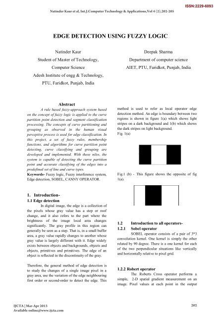
method is used to refer as local operator <strong>edge</strong><br />
<strong>detection</strong> method. An <strong>edge</strong> is boundary between two<br />
regions is shown in figure 1(a) which shows light<br />
stripes on a dark background and 1(b) which shows<br />
the dark stripes on light background.<br />
Fig. 1(a)<br />
Fig.1 (b) - This figure shows the opposite <strong>of</strong> fig<br />
1(a).<br />
1. Introduction-<br />
1.1 Edge <strong>detection</strong><br />
In digital image, the <strong>edge</strong> is a collection <strong>of</strong><br />
the pixels whose gray value has a step or ro<strong>of</strong><br />
change, and it also refers to the part where the<br />
brightness <strong>of</strong> the image local area changes<br />
significantly. The gray pr<strong>of</strong>ile in this region can<br />
generally be seen as a step. That is, in a small buffer<br />
area, a gray value rapidly changes to another whose<br />
gray value is largely different with it. Edge widely<br />
exists between objects and backgrounds, objects and<br />
objects, primitives and primitives. The <strong>edge</strong> <strong>of</strong> an<br />
object is reflected in the discontinuity <strong>of</strong> the gray.<br />
Therefore, the general method <strong>of</strong> <strong>edge</strong> <strong>detection</strong> is<br />
to study the changes <strong>of</strong> a single image pixel in a<br />
gray area, use the variation <strong>of</strong> the <strong>edge</strong> neighbouring<br />
first order or second-order to detect the <strong>edge</strong>. This<br />
1.2 Introduction to all operators-<br />
1.2.1 Sobel operator<br />
SOBEL operator consists <strong>of</strong> a pair <strong>of</strong> 3*3<br />
convolution kernel. One kernel is simply the other<br />
related by 90 degree. There is a one kernel for each<br />
<strong>of</strong> the two perpendicular situations like vertically<br />
and horizontally relative to pixel grid.<br />
1.2.2 Robert operator<br />
The Roberts Cross operator performs a<br />
simple, 2-D spatial gradient measurement on an<br />
image. Pixel values at each point in the output<br />
IJCTA | Mar-Apr 2013<br />
Available online@www.ijcta.com<br />
202
Natinder Kaur et al, Int.J.<strong>Computer</strong> Technology & Applications,Vol 4 (2),202-205<br />
ISSN:2229-6093<br />
represent the estimated absolute magnitude <strong>of</strong> the<br />
spatial gradient <strong>of</strong> the input image at that point. The<br />
operator consists <strong>of</strong> a pair <strong>of</strong> 2×2 convolution<br />
kernels.<br />
1.2.3 Prewitt operator<br />
Prewitt operator is similar to the SOBEL<br />
operator and is used for detecting vertical and<br />
horizontal <strong>edge</strong>s in images.<br />
1.2.4 Laplacian <strong>of</strong> Gaussian operator<br />
This is 2-D Isotropic measure <strong>of</strong> second<br />
spatial derivative <strong>of</strong> an image. The region <strong>of</strong> Rapid<br />
intensity change is given by LAPLACIAN so it is<br />
used to detect the <strong>edge</strong>s. It is used to reduce the<br />
noise. It uses Gaussian smoothing filter in order to<br />
reduce the noise. This operator takes a single gray<br />
level image as input and produces another gray level<br />
image as output.<br />
1.2.5 Canny operator<br />
The Canny Edge Detector is one <strong>of</strong> the most<br />
commonly used image processing tools, detecting<br />
<strong>edge</strong>s in a very robust manner. It is a multi-step<br />
process, which can be implemented on the GPU as a<br />
sequence <strong>of</strong> filters. Traditional operators like<br />
SOBEL, ROBERT,PREWITT, LAPLACIAN OF<br />
GAUSSIAN are widely used but most <strong>of</strong> these are<br />
very sensitive to noise and do not give satisfactory<br />
results. Canny operator removes all these problems<br />
but it does not give the good result in varying<br />
contrast areas. A Fuzzy <strong>logic</strong> <strong>edge</strong> detector avoids<br />
all these problems.<br />
2. A Brief review on Fuzzy <strong>logic</strong><br />
2.1 Introduction<br />
Fuzzy <strong>logic</strong> was first introduced in the<br />
1965 as a new way to represent vagueness in<br />
everyday life. The definition <strong>of</strong> <strong>fuzzy</strong> <strong>logic</strong> as a<br />
superset <strong>of</strong> conventional (Boolean) <strong>logic</strong> that has<br />
been extended to handle the concept <strong>of</strong> partial time<br />
values between "completely true" and "completely<br />
false" By this definition, <strong>fuzzy</strong> <strong>logic</strong> departs from<br />
classical two-valued set <strong>logic</strong>. It uses s<strong>of</strong>t linguistic<br />
system variables and a continuous range <strong>of</strong> true<br />
values in the interval [O, 1], rather than strict<br />
binary values. It is basically a multivalued <strong>logic</strong><br />
that allows intermediate values to be defined<br />
between conventional evaluations like yes/no,<br />
true/false, etc. Fuzzy <strong>logic</strong> is also a structured,<br />
model-free estimator that approximates a function<br />
through linguistic input/output associations. Fuzzy<br />
<strong>logic</strong> is a powerful, yet straight forward, problem<br />
solving technique with wide spread applicability,<br />
special in the areas <strong>of</strong> control and decision making<br />
2.2 Fuzzy <strong>logic</strong> has many applications such<br />
as:<br />
Control system (Robotics, Automation,<br />
Tracking, consumer Electronics).<br />
Information systems (DBMS, Information<br />
Retrieval).<br />
Pattern recognition (Image Processing,<br />
Machine Vision).<br />
Decision support (Adaptive HMI, Sensor<br />
Fusion).<br />
2.3 Structure <strong>of</strong> Fuzzy Image Processing<br />
Fuzzy image processing is not a unique<br />
theory. Fuzzy image processing is the collection <strong>of</strong><br />
all approaches that understand, represent and<br />
process the images, their segments and features as<br />
<strong>fuzzy</strong> sets. The representation and processing<br />
depend on the selected <strong>fuzzy</strong> technique and on the<br />
problem to be solved. Fuzzy image processing has<br />
three main stages: image fuzzification modification<br />
<strong>of</strong> membership values, and, if necessary, image<br />
defuzzification is shown in figure 2.3(a). The<br />
fuzzification and defuzzification steps are due to<br />
non availability <strong>fuzzy</strong> hardware. Therefore, the<br />
coding <strong>of</strong> image data and decoding <strong>of</strong> the results are<br />
steps that make possible to process images with<br />
<strong>fuzzy</strong> techniques. The main power <strong>of</strong> <strong>fuzzy</strong> image<br />
processing is in the middle step i.e. modification <strong>of</strong><br />
membership values.<br />
IJCTA | Mar-Apr 2013<br />
Available online@www.ijcta.com<br />
203
Natinder Kaur et al, Int.J.<strong>Computer</strong> Technology & Applications,Vol 4 (2),202-205<br />
ISSN:2229-6093<br />
Expert<br />
Knowl<strong>edge</strong><br />
pixels i.e. p1, p2, p3, p4, p6, p7, p8 & p9 are white.<br />
Such types <strong>of</strong> falsely marked <strong>edge</strong> pixels are<br />
changed to White by the noise removal algorithm.<br />
Input<br />
I mage<br />
Fuzz.<br />
Membership<br />
modification<br />
Image<br />
Defuzz.<br />
Fuzzy <strong>logic</strong><br />
Result<br />
Figure 2.3(a) general Set theory structure <strong>of</strong> <strong>fuzzy</strong> image<br />
processing.<br />
3. Fuzzy <strong>logic</strong> Algorithm<br />
For <strong>edge</strong> <strong>detection</strong> a set <strong>of</strong> nine pixels, part<br />
<strong>of</strong> a 3x3 or 5x5 window <strong>of</strong> an image to a set <strong>of</strong><br />
<strong>fuzzy</strong> conditions which help to highlight all the<br />
<strong>edge</strong>s that are associated with an image. The<br />
<strong>fuzzy</strong> conditions help to test the relative values<br />
<strong>of</strong> pixels which can be present in case <strong>of</strong><br />
presence on an <strong>edge</strong> in a gray scale image. This<br />
is shown in figure.<br />
3.1 Noise Removal<br />
Noise removal is performed at different<br />
intermediate levels <strong>of</strong> processing. The idea <strong>of</strong> noise<br />
removal is to remove the pixels which have been<br />
falsely recognized as <strong>edge</strong> by the processing. Size <strong>of</strong><br />
the scanning mask for this task is 3*3 pixels<br />
window. 3*3 pixels mask is slid over the whole<br />
image pixel by pixel row wise and the process<br />
continues till the time whole image is scanned for<br />
unwanted <strong>edge</strong> pixels. Fig. 3.1(a) shows p5 as<br />
falsely marked <strong>edge</strong> pixel as all the surrounding<br />
Figure 3.1(a) false marked <strong>edge</strong> pixel.<br />
Every pixel in the input image is evaluated<br />
with its eight neighbours, <strong>using</strong> each <strong>of</strong> the three<br />
masks shown in Figure 1 to produce <strong>edge</strong> strength<br />
value. The equation used for the calculation <strong>of</strong><br />
edginess values between the centre pixel and the<br />
neighbourhood pixels <strong>of</strong> the three (3) masks <strong>using</strong><br />
spatial convolution process is given by:<br />
О(x, y)=a I(X-1,Y-1)+b I(X-1,Y)+c I(X-1,Y+1)<br />
+d I(X, Y-1) +e I(X, Y) + f I(X, Y+1)+<br />
g I(X+1, Y-1)+h I(X+1,Y)+ i I(X+1,Y+1)<br />
--------------------1<br />
However, the result <strong>of</strong> convolution <strong>of</strong> the two Sobel<br />
kernels is combine thus, the approximate absolute<br />
gradient magnitude at each point is computed as:<br />
Οg = |Οx| + |Οy|<br />
--------------------2<br />
The normal <strong>edge</strong> strength is given by<br />
NΟ (x, y) = round [(Ο(x, y) /max (Ο)) × 100]<br />
------------------------3<br />
where x = {0,1, . . . ,M −1} and y = {0,1, . . . , N<br />
−1}foran M-by-N image. The <strong>edge</strong> strength values<br />
derived from the three (3) masks served as the<br />
inputs used in the construction <strong>of</strong> the <strong>fuzzy</strong><br />
inference system based on which decision on pixel<br />
as<br />
belonging to an <strong>edge</strong> or not are made. Membership<br />
functions are defined for <strong>fuzzy</strong> system inputs. Many<br />
membership functions have been introduced in the<br />
literature.<br />
u mn = G x mn = e [−(x mn −x mn ) 2 /2σ 2 ]<br />
a b c<br />
d e f<br />
g h i<br />
4<br />
……..<br />
IJCTA | Mar-Apr 2013<br />
Available online@www.ijcta.com<br />
204
Natinder Kaur et al, Int.J.<strong>Computer</strong> Technology & Applications,Vol 4 (2),202-205<br />
ISSN:2229-6093<br />
Every pixel in the input image is evaluated<br />
with its eight neighbors, <strong>using</strong> each <strong>of</strong> the three<br />
masks shown in Figure 1 to produce <strong>edge</strong> strength<br />
value. The equation used for the calculation <strong>of</strong><br />
edginess values between the center pixel and the<br />
neighborhood pixels <strong>of</strong> the three (3) masks <strong>using</strong><br />
spatial convolution process is given by: In the<br />
proposed <strong>edge</strong> <strong>detection</strong> Gaussian membership<br />
functions are used. To apply these functions, each <strong>of</strong><br />
the <strong>edge</strong> strength values <strong>of</strong> g Hp Lp O , O , and O<br />
are mapped into <strong>fuzzy</strong> domain between 0 and1,<br />
relative to the normalized gray levels between 0 and<br />
100, <strong>using</strong> Gaussian membership functions given as<br />
h LP =<br />
h x =<br />
1<br />
9<br />
1<br />
9<br />
1<br />
9<br />
1<br />
9<br />
1<br />
9<br />
1<br />
9<br />
1<br />
9<br />
1<br />
9<br />
1<br />
9<br />
−1 0 +1<br />
−2 0 +2<br />
−1 0 +1<br />
, h HP =<br />
, h y =<br />
−1 −1 −1<br />
−1 9 −1<br />
−1 −1 −1<br />
+1 +2 +1<br />
0 0 0<br />
−1 −2 −1<br />
Fig : 3×3 kernels used for <strong>edge</strong> <strong>detection</strong><br />
Each <strong>of</strong> the mapped values are partition<br />
into three <strong>fuzzy</strong> regions Lo w‖, Me dium‖, and H<br />
igh‖. The defined regions and membership functions<br />
are shown in Fig. 2. Fuzzy inference rules are<br />
applied to assign the three <strong>fuzzy</strong> sets characterized<br />
by membership functions Low Medium High , , and<br />
to the output set. The rules, tabulated in Table 1 are<br />
defined in such a way that in the <strong>fuzzy</strong> inference<br />
system, output set L M H E , E , and E correspond<br />
to pixels with low, medium and igh probability<br />
value respectively. The output <strong>of</strong> the system Final P<br />
representing the probability used for final pixel<br />
classification as <strong>edge</strong> or non-<strong>edge</strong> was computed<br />
<strong>using</strong> a singleton fuzzifier, Mamdani defuzzifier<br />
method given by;<br />
P Final =<br />
M<br />
e=1<br />
M<br />
e=1<br />
y −e n<br />
( i=1 u ki<br />
e (a i ))<br />
(<br />
n<br />
i=1<br />
u ki<br />
e (a i ))<br />
Conclusions and Future work<br />
Although the proposed <strong>fuzzy</strong> system for<br />
curve partition point <strong>detection</strong> and segment<br />
classification works very well, more research work<br />
is needed for further improving the performance <strong>of</strong><br />
the system.<br />
1. Testing more images should increase the rate <strong>of</strong><br />
finding correct CPPs and classifying segments by<br />
obtaining better <strong>fuzzy</strong> rnembership function<br />
parameters and filter sizes.<br />
2. Developing <strong>fuzzy</strong> algorithms should help find<br />
join points on <strong>edge</strong> data since the current proposed<br />
<strong>fuzzy</strong> system does not define the rules for detecting<br />
join points (the join point is a point which connects<br />
two same type curve segments). Figure below<br />
shows the join points (small black squares).<br />
REFERENCES<br />
[1] Ng Geok See and Chan Khue hiang. “Edge<br />
Detection <strong>using</strong> supervised Learning and voting<br />
scheme”. Nanyang Techno<strong>logic</strong>al University,<br />
National university <strong>of</strong> Singapore, Singapore.<br />
[2] Hamid R. Tizhoosh, “Fuzzy Image Processing”.<br />
www.pami.uwaterloo.ca/tizhoosh/<strong>edge</strong>.html<br />
[3] Md. Shoiab Bhuiyan, Yuiji Iwahori, and Akira<br />
Iwata. “Optimal <strong>edge</strong> <strong>detection</strong> under difficult<br />
imaging conditions”. Technical report, Educational<br />
Center for<br />
Information Processing and Dept. <strong>of</strong> Electrical and<br />
<strong>Computer</strong> Engineering,<br />
Nagoya Institute <strong>of</strong> Technology, Showa, Nagoya,<br />
466-8555, JAPAN,<br />
URL:-<br />
http://www.center.nitech.ac.jp/people/bhuiyan<br />
/pub.html.<br />
[4] Ursula Kretschmer, Maria S. Orozco, Oscar E.<br />
Ruiz and Uwe Jasnoch, “Edge and corner<br />
identification for tracking the line <strong>of</strong> sight”.<br />
[5] Renyan Zhang, Guoling Zhao, Li Su. “New <strong>edge</strong><br />
<strong>detection</strong> method in image processing”. College <strong>of</strong><br />
Autom., Harbin Engineering University, China.<br />
[6] Zhengquan He, M.Y.Siyal. “An image <strong>detection</strong><br />
technique based on morpho<strong>logic</strong>al <strong>edge</strong> <strong>detection</strong><br />
and background differencing for real-time traffic<br />
analysis”. Elsevier Science Inc. New York, NY,<br />
USA<br />
IJCTA | Mar-Apr 2013<br />
Available online@www.ijcta.com<br />
205


