Implementation of Wallace Tree Multiplier Using Compressor
Implementation of Wallace Tree Multiplier Using Compressor
Implementation of Wallace Tree Multiplier Using Compressor

You also want an ePaper? Increase the reach of your titles
YUMPU automatically turns print PDFs into web optimized ePapers that Google loves.
Naveen Kr.Gahlan et al ,Int.J.Computer Technology & Applications,Vol 3 (3), 1194-1199<br />
ISSN:2229-6093<br />
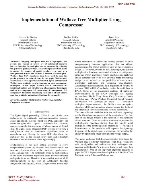
<strong>Implementation</strong> <strong>of</strong> <strong>Wallace</strong> <strong>Tree</strong> <strong>Multiplier</strong> <strong>Using</strong><br />
<strong>Compressor</strong><br />
Naveen Kr. Gahlan<br />
Research Scholar<br />
Department <strong>of</strong> E&Ec<br />
PEC University <strong>of</strong> Technology<br />
Chandigarh, India<br />
Prabhat Shukla<br />
Research Scholar<br />
Department <strong>of</strong> E&Ec<br />
PEC University <strong>of</strong> Technology<br />
Chandigarh, India<br />
Jasbir Kaur<br />
Assistant Pr<strong>of</strong>essor<br />
Department <strong>of</strong> E&Ec<br />
PEC University <strong>of</strong> Technology<br />
Chandigarh, India<br />
Abstract— Designing multipliers that are <strong>of</strong> high-speed, low<br />
power, and regular in layout are <strong>of</strong> substantial research<br />
interest. Speed <strong>of</strong> the multiplier can be increased by reducing<br />
the generated partial products. Many attempts have been made<br />
to reduce the number <strong>of</strong> partial products generated in a<br />
multiplication process one <strong>of</strong> them is <strong>Wallace</strong> tree multiplier.<br />
<strong>Wallace</strong> <strong>Tree</strong> CSA structures have been used to sum the<br />
partial products in reduced time. In this paper <strong>Wallace</strong> tree<br />
construction is investigated and evaluated. Speed <strong>of</strong> traditional<br />
<strong>Wallace</strong> tree multiplier can be improve by using compressor<br />
techniques. In this paper <strong>Wallace</strong> tree is constructed by<br />
traditional method and with the help <strong>of</strong> compressor techniques<br />
such as 4:2 compressor, 5:2 compressor, 6:2 compressor, 7:2<br />
compressor. Therefore, minimizing the number <strong>of</strong> half adders<br />
used in a multiplier reduction will reduce the complexity<br />
Keywords-<strong>Multiplier</strong>, Multiplication, <strong>Wallace</strong> <strong>Tree</strong> <strong>Multiplier</strong>,<br />
<strong>Compressor</strong> techniques<br />
I. INTRODUCTION<br />
The digital signal processing (DSP) is one <strong>of</strong> the core<br />
technologies in multimedia and communication systems.<br />
Many application systems based on DSP, especially the<br />
recent next-generation optical communication systems,<br />
require extremely fast processing <strong>of</strong> a huge amount <strong>of</strong> digital<br />
data [4]. Digital signal processor (DSP) systems incorporate a<br />
multiplication unit to implement algorithms such as<br />
convolution and filtering. In many DSP algorithms, the<br />
multiplier lies in the critical delay path and ultimately<br />
determines the performance <strong>of</strong> the algorithm [6].<br />
Multiplication is the most critical operation in every<br />
computational system [8]. Graphics and Process control are<br />
two more domains where in the multiplier performance<br />
plays a crucial role. The bottlenecks posed by multiplication<br />
in the above mentioned application areas are both temporal<br />
and spatial in nature. Therefore it appears that, custom VLSI<br />
implementations in the form <strong>of</strong> Application Specific<br />
Integrated Circuits (ASIC) or the DSP processors are the only<br />
viable alternatives to address the latency demands <strong>of</strong> such<br />
computationally intensive applications, that too without<br />
compromising the spatial aspects in view <strong>of</strong> the propagation<br />
delays [2]. However, even in the FPGA paradigm, the custom<br />
multiplication hardware embedded within a reconfigurable<br />
array has shown promising results and hence is a preferred<br />
choice currently due to the cost effective rapid prototyping<br />
design cycles as well as the possibility <strong>of</strong> concurrency,<br />
distributed arithmetic and extensive specialization.<br />
Accordingly many researchers have implemented variants <strong>of</strong><br />
the basic „Shift Addition‟ method to realize the multipliers in<br />
FPGA. Some <strong>of</strong> the preeminent methods <strong>of</strong> multiplier<br />
implementation in the FPGA paradigm are Scaling<br />
Accumulator, Ripple Carry Array, Carry Save Array, Look-<br />
Up Table and Partial Product, Computed Partial Product,<br />
and <strong>Wallace</strong> <strong>Tree</strong>s. Amongst the above mentioned<br />
multiplier implementations, the <strong>Wallace</strong> tree multipliers<br />
stimulate VLSI implementation interests reduce the depth <strong>of</strong><br />
the adder chain thereby minimizing the time complexity.<br />
The most efficient multiplier structure will vary depending<br />
on the throughput requirement <strong>of</strong> the application. The first<br />
step <strong>of</strong> the design process is the selection <strong>of</strong> the optimum<br />
circuit structure. There are various structures to perform the<br />
multiplication operation starting from the simple serial<br />
multipliers to the complex parallel multipliers [1]. Any speed<br />
improvement in the multiplier will improve the operating<br />
frequency <strong>of</strong> the digital signal processors or can be traded for<br />
energy by optimizing circuit sizes and the voltage supply.<br />
This paper addresses high-level optimization techniques for<br />
<strong>Wallace</strong> <strong>Tree</strong> <strong>Multiplier</strong> multipliers. High-level techniques<br />
refer to algorithm and architecture level techniques that<br />
consider multiplication‟s arithmetic features and input data<br />
characteristics. One <strong>of</strong> the important algorithm presents in<br />
paper for VLSI implementable multiplication is <strong>Wallace</strong> <strong>Tree</strong><br />
<strong>Multiplier</strong> using Xilinx and Cadence tool.<br />
IJCTA | MAY-JUNE 2012<br />
Available online@www.ijcta.com<br />
1194
Naveen Kr.Gahlan et al ,Int.J.Computer Technology & Applications,Vol 3 (3), 1194-1199<br />
ISSN:2229-6093<br />
II.<br />
MULTIPLIER<br />
A basic multiplier can consist <strong>of</strong> three parts (i) partial<br />
product generation (iii) partial product addition and (iii) final<br />
addition [9]. A multiplier essentially consist <strong>of</strong> two operands,<br />
a multiplicand “Y” and a multiplier “X” and produces a<br />
product “. In the first stage, the multiplicand and the<br />
multiplier are multiplied bit by bit to generate the partial<br />
products product The second stage is the most important, as<br />
it is the most complicated and determines the speed <strong>of</strong> the<br />
overall multiplier to add these partial product to generate the<br />
Product “P”. This paper will be focused on the optimization<br />
<strong>of</strong> this stage, which consists <strong>of</strong> the addition <strong>of</strong> all the partial<br />
products. If speed is not an issue, the partial products can be<br />
added serially, reducing the design complexity. However, in<br />
high- speed design, the <strong>Wallace</strong> tree construction method is<br />
usually used to add the partial products in a tree-like fashion<br />
in order to produce two rows <strong>of</strong> partial products that can be<br />
added in the last stage. Although fast, since its critical path<br />
delay is proportional to the logarithm <strong>of</strong> the number <strong>of</strong> bits in<br />
the multiplier, the <strong>Wallace</strong> tree introduces other problems<br />
such as wasted layout area and increased complexity. In the<br />
last stage, the two-row outputs <strong>of</strong> the tree are added using<br />
any high-speed adder such as carry save adder to generate<br />
the output result.<br />
Fig.1. Logic used in 4 bit <strong>Wallace</strong> <strong>Tree</strong> <strong>Multiplier</strong><br />
III.<br />
WALLACE TREE MULTIPLIER<br />
A fast process for multiplication <strong>of</strong> two numbers was<br />
developed by <strong>Wallace</strong> [7]. <strong>Using</strong> this method, a three step<br />
process is used to multiply two numbers; the bit products<br />
are formed, the bit product matrix is reduced to a two row<br />
matrix where sum <strong>of</strong> the row equals the sum <strong>of</strong> bit<br />
products, and the two resulting rows are summed with a<br />
fast adder to produce a final product.<br />
In the <strong>Wallace</strong> <strong>Tree</strong> method, three bit signals are<br />
passed to a one bit full adder (“3W”) which is called a three<br />
input <strong>Wallace</strong> <strong>Tree</strong> circuit, and the output signal (sum signal)<br />
is supplied to the next stage full adder <strong>of</strong> the same bit, and<br />
the carry output signal there<strong>of</strong> is passed to the next<br />
stage full adder <strong>of</strong> the same no <strong>of</strong> bit, and the carry output<br />
signal there<strong>of</strong> is supplied to the next stage <strong>of</strong> the full adder<br />
located at a one bit higher position[5].<br />
Fig.2. <strong>Wallace</strong> <strong>Tree</strong> <strong>Multiplier</strong><br />
Fig.3. RTL Schematic <strong>of</strong>4 bit <strong>Wallace</strong> <strong>Tree</strong> <strong>Multiplier</strong><br />
IJCTA | MAY-JUNE 2012<br />
Available online@www.ijcta.com<br />
1195
Naveen Kr.Gahlan et al ,Int.J.Computer Technology & Applications,Vol 3 (3), 1194-1199<br />
ISSN:2229-6093<br />
Fig.5. (a) 4:2 compressor I/O diagram; (b) 4:2 compressor architecture;<br />
Fig.4. Logic used in 8 bit <strong>Wallace</strong> <strong>Tree</strong> <strong>Multiplier</strong><br />
A 8-bit multiplier is constructed by using <strong>Wallace</strong> tree<br />
architecture .The architecture has been shown in Figure 3.<br />
Partial products are added in 6 steps. In the <strong>Wallace</strong> <strong>Tree</strong><br />
method, the circuit layout is not easy although the speed <strong>of</strong><br />
the operation is high since the circuit is quite irregular [3].<br />
The delay generated in wallace tree multiplier can be further<br />
reduced by using modified tree structures called<br />
compressors.<br />
Fig.5(c). RTL Schematic <strong>of</strong> 4:2 <strong>Compressor</strong><br />
IV.<br />
COMPRESSOR<br />
<strong>Compressor</strong>s are arithmetic components, similar in<br />
principle to parallel counters, but with two distinct<br />
differences: (1) they have explicit carry-in and carry-out<br />
bits; and (2) there may be some redundancy among the<br />
ranks <strong>of</strong> the sum and carry-output bits.<br />
1) 4:2 <strong>Compressor</strong><br />
The 4:2 compressor has 4 input bits and produces 2 sum<br />
output bits (out0 and out1 ), it also has a carry-in (cin) and<br />
a carry-out (cout) bit (thus, the total number <strong>of</strong> input/output<br />
bits are 5 and 3); All input bits, including cin, have rank 0;<br />
the two output bits have ranks 0 and 1 respectively, while<br />
cout has rank 1 as well. Thus, the output <strong>of</strong> the 4:2<br />
compressor is a redundant number; for example, out1 = 0<br />
and cout = 1 is equivalent to out1 = 1 and cout = 0 in all<br />
cases.<br />
Fig.4. Logic used in 4 bit <strong>Wallace</strong> <strong>Tree</strong> <strong>Multiplier</strong> using 4:2 <strong>Compressor</strong><br />
2) 5:2 <strong>Compressor</strong><br />
The 5:2 compressor has 5 input bits and produces 2 sum<br />
output bits (sum and cout3), it also has a carry-in (cin1,<br />
cin2) and a carry-out (cout1, cout2,cout3) bit (thus, the total<br />
number <strong>of</strong> input/output bits are 7 and 4); All input bits,<br />
including cin1, have rank 0 and cin2 has rank 2 ; the two<br />
output bits have ranks 0 and 1 respectively, while cout2 has<br />
rank 1 and cout1 has rank 2 as shown in Fig<br />
IJCTA | MAY-JUNE 2012<br />
Available online@www.ijcta.com<br />
1196
Naveen Kr.Gahlan et al ,Int.J.Computer Technology & Applications,Vol 3 (3), 1194-1199<br />
ISSN:2229-6093<br />
Fig.6. (a) 5:2 compressor I/O diagram<br />
Fig.7(b) 6:2 compressor architecture<br />
Fig.6(b). RTL Schematic <strong>of</strong> 5:2 <strong>Compressor</strong><br />
3) 6:2 <strong>Compressor</strong><br />
The 6:2 compressor has 6 input bits and produces 2 sum<br />
output bits (out 0 and out 1 ), it also has a carry-in (C in0 ,<br />
C in1 ) and a carry-out (C out0 , C out1 ) bit (thus, the total number<br />
<strong>of</strong> input/output bits are 8 and 4); All input bits, including<br />
C in0 , have rank 0 and C in1 has rank 1 ; the two output bits<br />
have ranks 0 and 1 respectively, while C out0 has rank 1 and<br />
C out1 has rank 2 as shown in Fig<br />
Fig.7(c). RTL Schematic <strong>of</strong> 6:2 <strong>Compressor</strong><br />
4) 7:2 <strong>Compressor</strong><br />
The 7:2 compressor has 7 input bits and produces 2 sum<br />
output bits (out 0 and out 1 ), it also has a carry-in (C in0 ,<br />
C in1 ) and a carry-out (C out0 , C out1 ) bit (thus, the total number<br />
<strong>of</strong> input/output bits are 9 and 4); All input bits, including<br />
C in0 , have rank 0 and C in1 has rank 1 ; the two output bits<br />
have ranks 0 and 1 respectively, while C out0 has rank 1 and<br />
C out1 has rank 2 as shown in Fig<br />
Fig.7(a) 6:2 compressor I/O diagram<br />
Fig.8(a) 6:2 compressor I/O diagram<br />
IJCTA | MAY-JUNE 2012<br />
Available online@www.ijcta.com<br />
1197
Naveen Kr.Gahlan et al ,Int.J.Computer Technology & Applications,Vol 3 (3), 1194-1199<br />
ISSN:2229-6093<br />
Fig.8(b) 6:2 compressor architecture<br />
Fig.9. Simulation result <strong>of</strong> 8 bit <strong>Wallace</strong> <strong>Tree</strong> <strong>Multiplier</strong><br />
VI.<br />
MULTIPLIER PERFORMANCE AND<br />
COMPARISON<br />
The performance analysis <strong>of</strong> <strong>Wallace</strong> <strong>Tree</strong> <strong>Multiplier</strong> using<br />
conventional method and using <strong>Compressor</strong> are listed in<br />
Tables 1-2 in terms <strong>of</strong> number <strong>of</strong> occupied slices, number<br />
<strong>of</strong> 4 input LUT using Xilinx and power, delay using<br />
Cadence tool. The simulation results <strong>of</strong> number <strong>of</strong> occupied<br />
slices and number <strong>of</strong> 4 input LUT are shown in Table-1.<br />
The simulation results <strong>of</strong> power and delay are shown in<br />
Table-2. Here <strong>Wallace</strong> <strong>Tree</strong> <strong>Multiplier</strong> represents as WTM<br />
in Table 1-2.<br />
Fig.8(c). RTL Schematic <strong>of</strong> 7:2 <strong>Compressor</strong><br />
V. VERIFICATION OF SIMULATION<br />
Xilinx is powerful simulation tool for simulate and compile<br />
Verilog/VHDL code efficiently. All the basic modules designed<br />
for <strong>Wallace</strong> tree multiplier are compiled and tested vigorously<br />
for functional correctness using waveforms. The complete<br />
circuit <strong>of</strong> 8×8 bit <strong>Wallace</strong> tree multiplier is described in<br />
Verilog, as a structural component. The hieratical structure is<br />
created and the complete simulation can be observed. Fig.3<br />
shows the waveform simulation result for the <strong>Wallace</strong> tree<br />
multiplier.<br />
<strong>Wallace</strong> <strong>Tree</strong><br />
<strong>Multiplier</strong> 4×4(WTM)<br />
Number <strong>of</strong><br />
Number <strong>of</strong><br />
4 input LUTs occupied Slices<br />
4×4 WTM 27 15<br />
4×4 WTM using 4:2<br />
<strong>Compressor</strong><br />
4×4 WTM using 5:2<br />
<strong>Compressor</strong><br />
39 20<br />
37 20<br />
8×8 WTM 139 75<br />
8×8 WTM using 5:2 &<br />
4 :2 <strong>Compressor</strong><br />
8×8 WTM using 6:2 &<br />
4:2 <strong>Compressor</strong><br />
8×8 WTM using 7:2 &<br />
4:2 <strong>Compressor</strong><br />
<strong>Wallace</strong> <strong>Tree</strong><br />
<strong>Multiplier</strong>(WTM)<br />
Table.1 Simulation Result using Xilinx<br />
Leakage<br />
Power<br />
Power<br />
(uW)<br />
139 75<br />
139 76<br />
140 74<br />
Dynamic<br />
Power<br />
Time Dealy<br />
(psec)<br />
4×4 WTM 1.078 10.835 0.921<br />
4×4 WTM using 4:2<br />
<strong>Compressor</strong><br />
4×4 WTM using 5:2<br />
<strong>Compressor</strong><br />
1.168 10.399 0.962<br />
1.080 10.746 0.896<br />
IJCTA | MAY-JUNE 2012<br />
Available online@www.ijcta.com<br />
1198
Naveen Kr.Gahlan et al ,Int.J.Computer Technology & Applications,Vol 3 (3), 1194-1199<br />
ISSN:2229-6093<br />
8×8 WTM 4.961 69.917 2.008<br />
8×8 WTM using 5:2<br />
& 4:2<strong>Compressor</strong><br />
8×8 WTM using 6:2<br />
& 4:2<strong>Compressor</strong><br />
8×8 WTM using 7:2<br />
& 4:2<strong>Compressor</strong><br />
5.178 74.642 2.128<br />
5.390 74.309 1.765<br />
5.698 74.278 1.526<br />
Table.2 Simulation Result using Cadence<br />
VII. CONCLUSIONS<br />
The <strong>Wallace</strong> tree multipliers can be solved & analyzed<br />
using a new modified method <strong>of</strong> <strong>Wallace</strong> tree construction<br />
using compressors. The modified tree has a slightly smaller<br />
critical path, a slightly larger wiring overhead but gives high<br />
speed.. This modified design <strong>of</strong> multiplier which consist <strong>of</strong><br />
7:2 compressor ,6:2 compressor ,5:2 compressor ,4:2<br />
compressor, 3:2 compressor, full adders and reduced no. <strong>of</strong><br />
half adder and reduces the complexity and reduce the time<br />
delay.<br />
<strong>Multiplier</strong> using <strong>Compressor</strong> have small increase in area and<br />
power but the time delay is less compare to conventional<br />
<strong>Wallace</strong> <strong>Tree</strong> <strong>Multiplier</strong>. As the <strong>Compressor</strong> order is<br />
increased the time delay reduces respectively. Hence for<br />
small delay requirement <strong>Wallace</strong> <strong>Tree</strong> <strong>Multiplier</strong> using<br />
compressor is suggested.<br />
References<br />
[1] Dursun Baran, Mustafa Aktan and Vojin G. Oklobdzija,” <strong>Multiplier</strong><br />
Structures for Low Power Applications in Deep-CMOS”, IEEE<br />
International Symposium on Circuits and Systems (ISCAS), 2011<br />
[2] S. A. Shinde, R. K. Kamat,” FPGA based Improved Hardware<br />
<strong>Implementation</strong> <strong>of</strong> Booth <strong>Wallace</strong> <strong>Multiplier</strong> using Handel C”,<br />
ELEKTRONIKA IR ELEKTROTECHNIKA,Page No.71-74, 2011<br />
[3] P.V. Rao, Cyril Prassana Raj P,S. Ravi,“VLSI Design and Analysis <strong>of</strong><br />
<strong>Multiplier</strong>s for Low Power”,IEEE 2009 Fifth International<br />
Conference On Intelligence Information Hiding and Multipedia<br />
Signal processing,pp. 1354-1357,2009<br />
[4] Soojin Kim, Kyeongsoon Cho,” Design <strong>of</strong> High-speed Modified<br />
Booth <strong>Multiplier</strong>s Operating at GHz Ranges”,World Academy <strong>of</strong><br />
Science ,Engineering and Technology,2010.<br />
[5] Sumit R. Vaidya, D.R. Dandekar,”Delay-power Performance<br />
Comparison <strong>of</strong> <strong>Multiplier</strong>s in VLSI Circuit Design”, IJCNC, vol.<br />
2,No. 4,pp. 47-56,July 2010<br />
[6] Issam S. Abu-Khater, Abdellatif Bellaouar, M. I. Elmasry, “Circuit<br />
Techniques for CMOS Low-Power High-Performance <strong>Multiplier</strong>s”,<br />
IEEE JOURNAL OF SOLID-STATE CIRCUITS, VOL. 31, NO.<br />
10,Page No.1535-1546, OCTOBER 1996<br />
[7] Prvinkumar G. Parate, Prafulla S. Patil, Dr (Mrs) S. Subbaraman<br />
“ASIC <strong>Implementation</strong> <strong>of</strong> 4 Bit <strong>Multiplier</strong>s”,IEEE First International<br />
Conference on Emerging Trends in Engineering and Technology, pp.<br />
408-413,2008<br />
[8] Kiaml Z. Pekmestzi,” Multiplexer-Based Array <strong>Multiplier</strong>s”, IEEE<br />
TRANSACTIONS ON COMPUTERS, VOL. 48, NO. 1, JANUARY<br />
1999.<br />
[9] N. Ravi, A.Satish , Dr. T. Jayachandra Prasad, Dr. T. Subba Rao,”A<br />
New Design for Array multiplier with Trade Off in power and Area”,<br />
IJCSI ,vol. 8,issue 3, May 2011<br />
IJCTA | MAY-JUNE 2012<br />
Available online@www.ijcta.com<br />
1199