Minimizing Push-out Delamination in Glass Fiber Reinforced
Minimizing Push-out Delamination in Glass Fiber Reinforced
Minimizing Push-out Delamination in Glass Fiber Reinforced

You also want an ePaper? Increase the reach of your titles
YUMPU automatically turns print PDFs into web optimized ePapers that Google loves.
International Journal of Applied Science and Technology Vol. 2 No. 3; March 2012<br />
<strong>M<strong>in</strong>imiz<strong>in</strong>g</strong> <strong>Push</strong>-<strong>out</strong> <strong>Delam<strong>in</strong>ation</strong> <strong>in</strong> <strong>Glass</strong> <strong>Fiber</strong> Re<strong>in</strong>forced Polyester Us<strong>in</strong>g RSM<br />
K.W. LIEW * , A. Ramasegar, M. Souiyah, N.S.M. El-Tayeb<br />
Mechanical Department<br />
Faculty of Eng<strong>in</strong>eer<strong>in</strong>g and Technology, Multimedia University<br />
Jalan Ayer Keroh Lama, 75450 Melaka<br />
Malaysia.<br />
Abstract<br />
<strong>Delam<strong>in</strong>ation</strong> of glass fiber re<strong>in</strong>forced polymer (GFRP) was studied us<strong>in</strong>g face centered central composite design<br />
(CCD) of Response Surface Methodology (RSM). The parameters <strong>in</strong>vestigated were drill diameter (4.5-11.5mm),<br />
speed (580-1420rpm) and feed rate (83-167mm/m<strong>in</strong>). Mathematical models were developed and verified with<br />
confirmation runs. The statistical significance of ma<strong>in</strong> parameters and their <strong>in</strong>teractions were determ<strong>in</strong>ed us<strong>in</strong>g<br />
Analysis of Variance (ANOVA). Drill<strong>in</strong>g of GFRP was performed us<strong>in</strong>g a CNC mach<strong>in</strong>e under dry conditions.<br />
The results showed that feed rate and speed were significant <strong>in</strong> <strong>in</strong>fluenc<strong>in</strong>g the formation of push-<strong>out</strong><br />
delam<strong>in</strong>ation. <strong>Delam<strong>in</strong>ation</strong> occurs least when speed is high and feed rate is low.<br />
Keywords: <strong>Glass</strong> <strong>Fiber</strong> Re<strong>in</strong>forced Polymer; <strong>Push</strong> Out <strong>Delam<strong>in</strong>ation</strong>; Dry Drill<strong>in</strong>g Parameters; Response<br />
Surface Methodology; ANOVA.<br />
1. Introduction<br />
<strong>Fiber</strong> re<strong>in</strong>forced polyester (FRP), commonly used to construct aircraft bodies or ships, is widely used <strong>in</strong> mak<strong>in</strong>g a<br />
wide range of products such as rocket launchers, w<strong>in</strong>dmill blades, VHS tra<strong>in</strong>s, automobiles and sports equipment.<br />
Due to its excellent physical properties, it now f<strong>in</strong>ds applications <strong>in</strong> civil eng<strong>in</strong>eer<strong>in</strong>g, such as <strong>in</strong> the mak<strong>in</strong>g of<br />
pipes due to their simple geometry. <strong>Glass</strong> fiber re<strong>in</strong>forced polymer (GFRP), one common type of FRP, is also<br />
widely used <strong>in</strong> various <strong>in</strong>dustries because of its excellent physical and mechanical properties such as high specific<br />
strength, high specific stiffness, excellent fatigue performance, light weight, good corrosion resistance and low<br />
thermal expansion (Abrao et al., 2007, Rubio et al.,2008, Connor and Zelen, 1959, Gaitonde et al., 2008, Hocheng<br />
and Dharan 1990, Hocheng and Tsao, 2003, Mohan et al., 2007, ,Tsao and Hocheng, 2004). Despite its apparent<br />
advantage, GFRP is difficult to mach<strong>in</strong>e. Delam<strong>in</strong>at<strong>in</strong>g is one of the major concerns when drill<strong>in</strong>g holes <strong>in</strong> GFRP,<br />
result<strong>in</strong>g <strong>in</strong> reduction of its strength and fatigue life, which <strong>in</strong> turns compromises the material usefulness.<br />
Therefore, <strong>in</strong> this study, glass fiber re<strong>in</strong>forced polyester (GFRP) is fabricated <strong>in</strong> FET, Multimedia University (El-<br />
Tayeb et al., 2006 and El-Tayeb et al., 2008) and the holes of different diameters are drilled on the GFRP us<strong>in</strong>g<br />
different speed and feed rates to identify optimum parameters to elim<strong>in</strong>ate or reduce delam<strong>in</strong>ation.<br />
<strong>Delam<strong>in</strong>ation</strong> happens easily when drill<strong>in</strong>g holes <strong>in</strong> composite materials, especially when the top and bottom<br />
surfaces of work piece are exposed (Rubio et al.,2008 and Mohan et al., 2007). In addition to reduc<strong>in</strong>g structural<br />
<strong>in</strong>tegrity of the lam<strong>in</strong>ate, delam<strong>in</strong>ation also results <strong>in</strong> poor assembly tolerance and long term performance<br />
deterioration (Connor and Zelen, 1959, Hocheng and Dharan, 1990, Ja<strong>in</strong> and Yang, 1994, Marques et al., 2009,<br />
Tsao and Hocheng, 2004, Tsao and Hocheng, 2008). Accord<strong>in</strong>g to statistics, it is estimated that drill<strong>in</strong>g-associated<br />
delam<strong>in</strong>ation accounts for 60% of all part rejections dur<strong>in</strong>g f<strong>in</strong>al assembly of an aircraft <strong>in</strong> the aircraft <strong>in</strong>dustry<br />
(Montgomery, 2005).<br />
<strong>Delam<strong>in</strong>ation</strong> is a mode of failure <strong>in</strong> composite materials which causes the lam<strong>in</strong>ates to separate. This leads to the<br />
form<strong>in</strong>g of a mica-like structure of separate layers, reduc<strong>in</strong>g the mechanical of toughness of the material. There<br />
are several types of delam<strong>in</strong>ation that can occur dur<strong>in</strong>g drill<strong>in</strong>g. However, two dist<strong>in</strong>guishable types of<br />
delam<strong>in</strong>ation, namely peel-up and push-<strong>out</strong> delam<strong>in</strong>ation, are common. The earlier occurs at the entrance of the<br />
drill hole while the latter occurs at the exit plane of the material. The damage caused by the push-<strong>out</strong> delam<strong>in</strong>ation<br />
is more extensive and is considered severer (Connor and Zelen, 1959). Dur<strong>in</strong>g drill<strong>in</strong>g, the drill exerts a<br />
compressive thrust force on the work material. The lam<strong>in</strong>ate under the drill tends to be drawn away from the <strong>in</strong>terlam<strong>in</strong>ar<br />
bond around the hole. Thus, as the drill approaches the end of the hole, the uncut thickness becomes<br />
lesser and hence the resistance to deformation decreases.<br />
183
© Centre for Promot<strong>in</strong>g Ideas, USA www.ijastnet .com<br />
This type of delam<strong>in</strong>ation is known as push-<strong>out</strong> delam<strong>in</strong>ation. At a certa<strong>in</strong> po<strong>in</strong>t the load<strong>in</strong>g exceeds the <strong>in</strong>terlam<strong>in</strong>ar<br />
bond strength and causes delam<strong>in</strong>ation to occur. On the other hand, the peel-up delam<strong>in</strong>ation occurs<br />
dur<strong>in</strong>g <strong>in</strong>itial stages where the cutt<strong>in</strong>g edge of the drill abrades the lam<strong>in</strong>ate. Subsequently, once the drill<strong>in</strong>g starts,<br />
the abraded material is pulled away along the flute caus<strong>in</strong>g the material to spiral up. This action <strong>in</strong>troduces an<br />
upwards peel<strong>in</strong>g force to separate the upper lam<strong>in</strong>as from the un-cut portion of the material held by the downward<br />
act<strong>in</strong>g thrust force. The force act<strong>in</strong>g <strong>in</strong> the tangential direction is the thrust force for delam<strong>in</strong>ation. A peel<strong>in</strong>g force<br />
<strong>in</strong> the axial direction is generated through the slope of the drill flute and is a function of tool geometry and friction<br />
between the work piece and the tool. In push-<strong>out</strong> delam<strong>in</strong>ation, the damage depends on the nature of fibre but also<br />
on the res<strong>in</strong> type and respective properties s<strong>in</strong>ce it occurs <strong>in</strong> the <strong>in</strong>ter-lam<strong>in</strong>ar region. Whereas, the peel-up<br />
delam<strong>in</strong>ation only occurs dur<strong>in</strong>g the beg<strong>in</strong>n<strong>in</strong>g stages of drill<strong>in</strong>g, ow<strong>in</strong>g to the fact that delam<strong>in</strong>ation gradually<br />
becomes difficult as the drill<strong>in</strong>g proceeds and the thickness resist<strong>in</strong>g the lam<strong>in</strong>a <strong>in</strong>creases (Ja<strong>in</strong> and Yang, 1994,<br />
Marques et al., 2009, Tsao and Hocheng, 2008). In the case of GFRP, delam<strong>in</strong>ation causes fiber pull <strong>out</strong> and<br />
cracks <strong>in</strong> the <strong>in</strong>terplay regions, thus reduc<strong>in</strong>g the stiffness and structural <strong>in</strong>tegration of the GFRP.<br />
GFRP has been the subject of extensive study dur<strong>in</strong>g the past decades. It was estimated that lam<strong>in</strong>ates made of an<br />
epoxy matrix re<strong>in</strong>forced with glass fibres account for over 50% of the total <strong>in</strong>vestigated polymeric composites,<br />
followed by carbon fibre re<strong>in</strong>forced epoxy of 30% and lastly, glass fibre re<strong>in</strong>forced with polyester res<strong>in</strong> of 14%.<br />
All <strong>in</strong> all, glass fiber re<strong>in</strong>forced polymer accounts for almost 70% of the <strong>in</strong>vestigated polymeric composite<br />
material (Abrao et al., 2007). Its prevalence <strong>in</strong> the current manufactur<strong>in</strong>g <strong>in</strong>dustry as well as <strong>in</strong> past researches is<br />
the primary motivation for the choice of material <strong>in</strong> this study. In addition, the Response Surface Methodology<br />
(RSM) employed <strong>in</strong> the present study is also a proven research methodology, <strong>in</strong> which a collection of<br />
mathematical and statistical analysis techniques is used to optimize a response of <strong>in</strong>terest that is <strong>in</strong>fluenced by<br />
several variables (Husnawan et al., 2007 and Montgomery, 2005). Gaitonde et. al. (2008) for <strong>in</strong>stance, had studied<br />
the parametric <strong>in</strong>fluences on delam<strong>in</strong>ation us<strong>in</strong>g RSM and concluded that low feed rates and high cutt<strong>in</strong>g speeds<br />
heavily <strong>in</strong>fluences the delam<strong>in</strong>ation at the entrance while validat<strong>in</strong>g the accuracy of the model (Gaitonde et al.,<br />
2008, Karnik et al., 2008). Mohan et.al. (2007) on the other hand, used RSM to predict optimal parameters and<br />
verify the model with experimental results to be with<strong>in</strong> 99% <strong>in</strong> agreement.<br />
In the present work, delam<strong>in</strong>ation of the GFRP was studied and analyzed us<strong>in</strong>g RSM under dry drill<strong>in</strong>g<br />
conditions. A second order l<strong>in</strong>ear regression model was developed for the range of data used <strong>in</strong> the experiment.<br />
The parameters used for this study are drill diameter, speed and feed rate. The mathematical model developed was<br />
later tested for significance us<strong>in</strong>g ANOVA. The results were then compared to experimental observations.<br />
2. Methodology<br />
Specimen Preparation<br />
The glass fiber re<strong>in</strong>forced composite used <strong>in</strong> this project is fabricated as previous method us<strong>in</strong>g a hand lay-up<br />
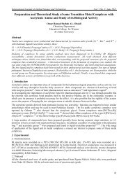
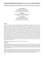
technique (El-Tayeb et al., 2006). The composition type is Chopped Strand Mat (CSM) (randomly oriented small<br />
cut lengths of fiber bonded together), as shown <strong>in</strong> Figure 1, with 450 R-glass fibers as re<strong>in</strong>forcement and<br />
polyester as the thermosett<strong>in</strong>g res<strong>in</strong> material (El-Tayeb et al., 2006 and El-Tayeb et al., 2008). The material was<br />
fabricated <strong>in</strong> large slabs and then cut <strong>in</strong>to pieces of 30mm × 30mm. The composition of the GFRP material used<br />
<strong>in</strong> the experiment is shown <strong>in</strong> Table 1.<br />
184<br />
Figure 1. SEM Micrograph of Chopped Strand Mat R-glass Fibre (El-Tayeb et al., 2006)
International Journal of Applied Science and Technology Vol. 2 No. 3; March 2012<br />
Table 1: Composition of GFRP (El-Tayeb et al., 2006).<br />
Items<br />
Quantity/Type<br />
Experimental Work<br />
<strong>Fiber</strong> Length<br />
20 - 30 mm<br />
Mass of <strong>Fiber</strong> 450 g/m 2<br />
Matrix<br />
Thermosett<strong>in</strong>g res<strong>in</strong><br />
Catalyst<br />
Methyl Ethyl Ketone Peroxide<br />
Re<strong>in</strong>forc<strong>in</strong>g<br />
CSM <strong>Glass</strong> <strong>Fiber</strong><br />
Drill<strong>in</strong>g was conducted on Master 10HVA CNC mach<strong>in</strong>e, Yamazaki Mazak, us<strong>in</strong>g high-speed steel drill<strong>in</strong>g tool<br />
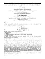
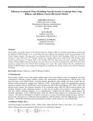
under dry conditions. The delam<strong>in</strong>ation factor (F d ) is calculated by divid<strong>in</strong>g the maximum delam<strong>in</strong>ated diameter<br />
(D max ) by the hole nom<strong>in</strong>al diameter (D) (Abrao et al., 2007, Rubio et al.,2008, Gaitonde et al., 2008, Hocheng<br />
and Tsao, 2003, Marques et al., 2009, Mohan et al., 2007, Tsao and Hocheng, 2004). This is shown <strong>in</strong> Equation 1.<br />
Figure 2 shows the scheme of the delam<strong>in</strong>ation factor.<br />
D<br />
F max<br />
d<br />
D<br />
(1)<br />
Response Surface Methodology<br />
Figure 2. Scheme of <strong>Delam<strong>in</strong>ation</strong> Factor.<br />
The data collected is analyzed statistically us<strong>in</strong>g regression. In this case, where a non-l<strong>in</strong>ear relationship between<br />
the response and <strong>in</strong>put variables are observed, a second order quadratic equation is used to describe the functional<br />
relationship between the estimated variable (delam<strong>in</strong>ation factor) and the <strong>in</strong>put variables {drill diameter (x 1 ),<br />
speed (x 2 ) and feed rate (x 3 )}. The relationship may be described by Equation 2.<br />
y x<br />
0<br />
1x1<br />
2x<br />
2<br />
3x<br />
3<br />
<br />
x x <br />
12 12 23 23 13x13<br />
2<br />
2<br />
2<br />
11x1<br />
22x<br />
2<br />
33x3<br />
(2)<br />
The least square method is used to fit the model equation conta<strong>in</strong><strong>in</strong>g the regressor or the <strong>in</strong>put variables. The β<br />
values can be obta<strong>in</strong>ed by perform<strong>in</strong>g matrix operations where β is replaced with matrix b. The solution of the<br />
normal equation can be written as<br />
T 1 T<br />
X<br />
X X y<br />
b (3)<br />
where X T is the transpose of matrix X (<strong>in</strong>put variables) and matrix (X T X) -1 is the <strong>in</strong>verse of matrix (X T X). y is to<br />
be def<strong>in</strong>ed as n × 1 matrix, X as n × m matrix of <strong>in</strong>dependent variables and b as an m × 1 matrix.<br />
185
© Centre for Promot<strong>in</strong>g Ideas, USA www.ijastnet .com<br />
Design of Experiment<br />
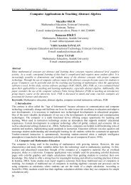
A total number of eighteen holes were drilled <strong>in</strong>to the GFRP specimen to develop a second order regression<br />
model to <strong>in</strong>vestigate the effects of drill diameter, speed and feed rate on delam<strong>in</strong>ation. For this experiment, we<br />
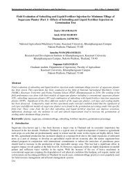
used the Central Composite Design (CCD) as shown <strong>in</strong> Figure 3 with a 3 factorial design with factor levels coded<br />
at -1 and +1. The axial portion (star po<strong>in</strong>ts) is located on the coord<strong>in</strong>ate axes of the factorial portion at an augment<br />
distance of α = 1.682 from the design centre, as shown <strong>in</strong> Table 2. Equation 4 shows how the raw data is<br />
converted <strong>in</strong>to coded form. The transformation of the <strong>in</strong>dependent variables <strong>in</strong>to five levels of coded form is as<br />
below<br />
x centre<br />
(4)<br />
high centre<br />
Table 2: Coded Form Distribution.<br />
Coded Form<br />
Parameter Lowest-<br />
1.682<br />
Low<br />
-1<br />
Center<br />
0<br />
High<br />
+1<br />
Highest<br />
1.682<br />
Diameter (mm) 4.5 6 8 10 11.5<br />
Speed (rpm) 580 750 1000 1250 1420<br />
Feed Rate (mm/m<strong>in</strong>) 83 100 125 150 167<br />
Figure 3. Central Composite Design.<br />
3. Results And Discussion<br />
The y parameter represents the delam<strong>in</strong>ation factor (F d ) while x 1 , x 2 and x 3 represent drill diameter, speed and feed<br />
rate respectively. The second order regression equation obta<strong>in</strong>ed from perform<strong>in</strong>g the matrix operations yielded<br />
Equation 5.<br />
186<br />
y 1.63391<br />
0.00925x<br />
0.04067x<br />
0.05326x<br />
0.0775x<br />
2<br />
3<br />
2<br />
3<br />
x<br />
3<br />
1<br />
0.05281x<br />
0.0175x<br />
2<br />
1<br />
1<br />
0.03798x<br />
x<br />
2<br />
0.01x<br />
1<br />
2<br />
0.01613x<br />
ANOVA is performed with a 95% confidence level. This means an acceptance of type one error, of 5%. As<br />
such, a term can apply only be considered <strong>in</strong>significant when its P-value is more than 0.05. The results show that<br />
some of the <strong>in</strong>teraction and quadratic terms are statistically not significant. These higher order terms with P>0.05<br />
are removed from equation (5) and the mathematical model thus reduced to equation (6).<br />
y 1.61329 0.00925x<br />
0.04067x<br />
2<br />
3<br />
0.0775x<br />
x<br />
3<br />
1<br />
0.05281x<br />
0.03798x<br />
2<br />
1<br />
2<br />
x<br />
0.04849x<br />
2<br />
2<br />
3<br />
2<br />
3<br />
(5)<br />
(6)
International Journal of Applied Science and Technology Vol. 2 No. 3; March 2012<br />
Table 3 (a): Analysis of Variance (ANOVA) Before Reduction.<br />
( a. Parameters ma<strong>in</strong> effects and <strong>in</strong>teractions; b. coefficient of model;<br />
c. standard error of coefficient; d. T-<br />
Ratio for test<strong>in</strong>g hypotheses;<br />
e. Significance probability for each T-ratio; f. Degree of Freedom; g. F-ratio<br />
for test<strong>in</strong>g hypotheses; h. Significance probability for each F-ratio)<br />
a. Term<br />
b. Coef<br />
c. SE Coef<br />
d. T<br />
e. P<br />
Constant 1.63391 0.04322 37.801 0<br />
x 1 0.00925 0.02030 -0.456 0.662<br />
x 2 0.03798 0.02030 -1.871 0.104<br />
x 3 0.04067 0.02030 2.004 0.085<br />
x 1 *x 1 0.05281 0.02234 2.364 0.050<br />
x 2 *x 2 0.01613 0.02234 -0.722 0.494<br />
x 3 *x 3 0.05326 0.02234 -2.384 0.049<br />
x 1 *x 2 -0.01750 0.02652 -0.66 0.530<br />
x 1 *x 3 0.01000 0.02652 0.377 0.717<br />
x 2 *x 3 0.07750 0.02652 2.922 0.022<br />
Source<br />
f. DF<br />
g. F<br />
h. P<br />
Regression 9 3.71 0.049<br />
L<strong>in</strong>ear 3 2.57 0.137<br />
Square 3 5.53 0.029<br />
Interaction 3 3.04 0.102<br />
Residual Error 7 -- --<br />
Lack-of-Fit 5 5.66 0.157<br />
Pure Error 2 -- --<br />
Total 16 -- --<br />
The result of ANOVA performed is tabulated <strong>in</strong> Table 3(a) for the orig<strong>in</strong>al model and Table 3(b) for the reduced<br />
model. It is observed that the P-values for the rema<strong>in</strong><strong>in</strong>g terms after reduction, except the ma<strong>in</strong> effect drill<br />
diameter (x 1 ) are less than 0.05, <strong>in</strong>dicat<strong>in</strong>g that the rema<strong>in</strong><strong>in</strong>g terms are statistically significant. This <strong>in</strong> turn leads<br />
to eng<strong>in</strong>eer<strong>in</strong>g observations that the <strong>in</strong>teraction between speed and feed rate (x 2 x 3 ), as well as the quadratic terms<br />
of drill diameter and feed rate (x 3 x 3 ) are significant <strong>in</strong> contribut<strong>in</strong>g to push-<strong>out</strong> delam<strong>in</strong>ation of the composite<br />
under study. There is no <strong>in</strong>teraction of drill diameter with the other two parameters, imply<strong>in</strong>g that the effect of<br />
drill diameter on delam<strong>in</strong>ation is <strong>in</strong>dependent. Look<strong>in</strong>g at the p-values of the lack of fit be<strong>in</strong>g greater than 0.05, it<br />
can be deduced that the reduced model appropriately describes the relationship between the <strong>in</strong>put parameters and<br />
the <strong>out</strong>put response.<br />
Table 3 (b): Analysis of Variance (ANOVA) After Reduction.<br />
Term Coef SE Coef T P<br />
Constant 1.61329 0.0292 55.241 0<br />
x 1 0.00925 0.01827 -0.507 0.623<br />
x 2 0.03798 0.01827 -2.079 0.064<br />
x 3 0.04067 0.01827 2.226 0.05<br />
x 1 *x 1 0.05758 0.01921 2.997 0.013<br />
x 3 *x 3 0.04849 0.01921 -2.524 0.03<br />
x 2 *x 3 0.0775 0.02387 3.247 0.009<br />
Source DF F P<br />
Regression 6 6.65 0.005<br />
L<strong>in</strong>ear 3 3.18 0.072<br />
Square 2 9.92 0.004<br />
Interaction 1 10.54 0.009<br />
Residual Error 10 -- --<br />
Lack-of-Fit 8 4.13 0.209<br />
Pure Error 2 -- --<br />
Total 16 -- --<br />
Figures 4 to Figure 6 are graphical representations of two-parameter <strong>in</strong>teractions based on the reduced<br />
mathematical models, taken at the mid sett<strong>in</strong>g of the unrepresented third parameter.<br />
187
© Centre for Promot<strong>in</strong>g Ideas, USA www.ijastnet .com<br />
These figures compare the effects of parameter <strong>in</strong>teractions (drill diameter/speed, feed rate/speed and feed<br />
rate/drill diameter) aga<strong>in</strong>st the delam<strong>in</strong>aton response <strong>in</strong> the form of response surfaces.<br />
Figure 4(a) and 4(b) show that a high drill<strong>in</strong>g speed significantly reduces the delam<strong>in</strong>ation while the <strong>in</strong>fluence of<br />
diameter does not exhibit a clear trend. Figure 5(a) and 5(b) clearly substantiates that high drill<strong>in</strong>g speed, when<br />
coupled with low feed rate, further m<strong>in</strong>imizes delam<strong>in</strong>ation. In addition, s<strong>in</strong>ce <strong>in</strong>creas<strong>in</strong>g speed at high feed rate<br />
does not help to reduce delam<strong>in</strong>ation, a strong <strong>in</strong>teraction exists between feed rate and speed. It is evident from<br />
Figure 6(a) and 6(b) that a larger or smaller than center value of drill diameter tends to <strong>in</strong>crease delam<strong>in</strong>ation.<br />
This corresponds to the statistical significant quadratic x 1 -term demonstrated <strong>in</strong> equation (6) and aga<strong>in</strong> <strong>in</strong> the<br />
saddleback shape of the surface plot <strong>in</strong> Figure 6(a). The fact that <strong>in</strong>creased speed lowers the amount of<br />
delam<strong>in</strong>ation may possibly be expla<strong>in</strong>ed by elevated cutt<strong>in</strong>g temperature, which promotes the soften<strong>in</strong>g of the<br />
matrix and therefore the ease of mach<strong>in</strong><strong>in</strong>g. On the same token, <strong>in</strong>creas<strong>in</strong>g feed rate <strong>in</strong>creases the thrust force,<br />
result<strong>in</strong>g <strong>in</strong> higher delam<strong>in</strong>ation.<br />
4(a)<br />
4(b)<br />
Figure 4. (a) Response Surface and; (b) Contour Plot of Effect of Drill Diameter and Drill<strong>in</strong>g Speed on the<br />
<strong>Delam<strong>in</strong>ation</strong>.<br />
5(a)<br />
5(b)<br />
Figure 5. (a) Response Surface and; (b) Contour Plot of Effect of Feed Rate and Drill<strong>in</strong>g Speed on the<br />
<strong>Delam<strong>in</strong>ation</strong>.<br />
188
International Journal of Applied Science and Technology Vol. 2 No. 3; March 2012<br />
6(a)<br />
6(b)<br />
Figure 6. (a) Response Surface and; (b) Contour Plot of Effect of Feed Rate and Drill Diameter on the<br />
<strong>Delam<strong>in</strong>ation</strong>.<br />
Figures 7(a) to Figure 7(d) show the residual plots for the reduced regression model. The normal probability plot<br />
(Figure 7(a)) reveals that the residuals generally fall on a straight l<strong>in</strong>e imply<strong>in</strong>g that the residuals are normally<br />
distributed. Figure 7 (b) cont<strong>in</strong>ues to imply that there are no obvious patterns and unusual features. Figure 7 (c)<br />
and Figure 7 (d) further verifies these analyses, as the residuals are random and there are no violations of the<br />
<strong>in</strong>dependence or equal variance assumptions.<br />
7(a)<br />
7(b)<br />
7(c)<br />
7(d)<br />
Figure 7. (a) Normal Probability Plot of Residual; (b) Residuals versus Fitted Values; (c) Histogram of<br />
Residuals; (d) Residuals Versus Order of Data.<br />
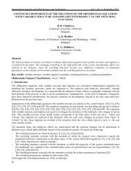
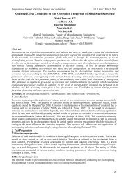
The comparison of the effect of speed and feed rate on the delam<strong>in</strong>ation phenomenon can be observed <strong>in</strong> Figures<br />
8(a)-(d). In Figure 8(a) and Figure 8(b), the same feed rate (125 mm/m<strong>in</strong>) and two different speeds (1000 rpm and<br />
580 rpm) had been used. It can be seen that the occurrence of the push-<strong>out</strong> delam<strong>in</strong>ation is more severe <strong>in</strong> Figure<br />
8(b)--the one with lower speed. A similar observation is made <strong>in</strong> Figure 8(c) and Figure 8(d). In Figure 8(c) speed<br />
and feed rate were set at 1250 rpm and 100 mm/m<strong>in</strong> respectively and m<strong>in</strong>imum delam<strong>in</strong>ation was observed.<br />
Whereas <strong>in</strong> Figure 8(d) when speed and feed rate were set at 580 rpm and 150 mm/m<strong>in</strong> respectively, severe<br />
delam<strong>in</strong>ation were seen.<br />
189
© Centre for Promot<strong>in</strong>g Ideas, USA www.ijastnet .com<br />
Figure 8. <strong>Delam<strong>in</strong>ation</strong> Observed <strong>in</strong> GFRP Us<strong>in</strong>g the Profile Projector at speed and feed rate. (a) 1000 rpm and<br />
125 mm/m<strong>in</strong>; (b) 580 rpm and 125 mm/m<strong>in</strong>; (c) 1250 rpm and 100 mm/m<strong>in</strong>; (d) 750 mm and 150 mm/m<strong>in</strong><br />
respectively.<br />
The mathematical model <strong>in</strong> equation (6) leads to m<strong>in</strong>imum predicted delam<strong>in</strong>ation of 1.125 at optimized sett<strong>in</strong>gs<br />
of drill<strong>in</strong>g speed at 1420 rpm and feed rate at 83 mm/m<strong>in</strong>, with a drill diameter of 8 mm. Three confirmation runs<br />
were conducted at the optimum sett<strong>in</strong>gs and the optimum responses averaged at 1.19, which is ab<strong>out</strong> 6% error<br />
compared to the predicted delam<strong>in</strong>ation value. These confirmation runs verified the mathematical model.<br />
4. Conclusion<br />
RSM was employed <strong>in</strong> this study based on a Central Composite Design (CCD) to develop a mathematical model<br />
that describes the effects of drill diameter, speed and feed rate on the push-<strong>out</strong> delam<strong>in</strong>ation <strong>in</strong> the GFRP material.<br />
A second order regression model was developed and 3D surface plots and contour plots were generated to analyze<br />
the two-factor <strong>in</strong>teraction of the parameters. The second order model developed is valid with<strong>in</strong> the ranges of the<br />
selected experimental parameters. ANOVA was done on the model to test for statistical significance. Based on the<br />
experimentations and statistical analyses carried <strong>out</strong>, the follow<strong>in</strong>g conclusions are drawn:<br />
<br />
<br />
<br />
<br />
ANOVA shows <strong>in</strong>significant lack of fit, validat<strong>in</strong>g the second order regression model.<br />
Speed and feed rate were significant parameters <strong>in</strong>volved <strong>in</strong> affect<strong>in</strong>g delam<strong>in</strong>ation. Strong <strong>in</strong>teractions<br />
between the two variables were noticed.<br />
Interactions <strong>in</strong>volv<strong>in</strong>g the drill diameter are <strong>in</strong>significant.<br />
Increas<strong>in</strong>g drill<strong>in</strong>g speed and decreas<strong>in</strong>g feed rate reduces delam<strong>in</strong>ation and m<strong>in</strong>imum delam<strong>in</strong>ation is<br />
achieved when drill<strong>in</strong>g speed is 1420 rpm and feed rate is 83 mm/m<strong>in</strong>, when a nom<strong>in</strong>al drill diameter of 8 mm<br />
190
International Journal of Applied Science and Technology Vol. 2 No. 3; March 2012<br />
References<br />
Abrao, A.M., P.E. Faria, J.C.C. Rubio, P. Reis and J.P. Davim, 2007. Drill<strong>in</strong>g of fibre re<strong>in</strong>forced plastics: A<br />
review. J. Mater. Process. Technol., 186: 1-7. DOI: 10.1016/j.jmatprotec.2006.11.146<br />
Rubio, J.C., A.M. Abrao, P.E. Faria, A.E. Correia and J.P. Davim, 2008. Effects of high speed <strong>in</strong> the drill<strong>in</strong>g of<br />
glass fibre re<strong>in</strong>forced plastic: Evaluation of the delam<strong>in</strong>ation factor. Int. J. Mach. Tools Manuf., 48: 715-<br />
720. DOI: 10.1016/j.ijmachtools.2007.10.015<br />
Connor, W.S. and M. Zelen, 1959. Fractional Factorial Experiment Designs for Factors at Three-Levels. Vol. 54,<br />
U.S. Government Pr<strong>in</strong>t<strong>in</strong>g Office, Wash<strong>in</strong>gton, DC., pp: 37.<br />
El-Tayeb, N.S.M., B.F. Yousif and T.C. Yap, 2008. An <strong>in</strong>vestigation on worn surfaces of chopped glass fibre<br />
re<strong>in</strong>forced polyester through SEM observations. Tribol. Int., 41: 331-340. DOI:<br />
10.1016/j.tribo<strong>in</strong>t.2007.07.007<br />
El-Tayeb, N.S.M., B.F. Yousif and T.C. Yap, 2006. Tribological studies of polyester re<strong>in</strong>forced with CSM 450-Rglass<br />
fiber slid<strong>in</strong>g aga<strong>in</strong>st smooth sta<strong>in</strong>less steel counterface. Wear, 261: 443-452. DOI:<br />
10.1016/j.wear.2005.12.014<br />
Gaitonde, V.N., S.R. Karni, J.C. Rubio, A.E. Correia, A.M. Abrao and J.P. Davim, 2008. Analysis of Parametric<br />
Influence on <strong>Delam<strong>in</strong>ation</strong> <strong>in</strong> High-Speed Drill<strong>in</strong>g of CFRP composites. J. Mater. Process. Technol., 203:<br />
431-438. DOI: 10.1016/j.jmatprotec.2007.10.050<br />
Hocheng, H. and K.H. Dharan, 1990. <strong>Delam<strong>in</strong>ation</strong> dur<strong>in</strong>g drill<strong>in</strong>g <strong>in</strong> composite lam<strong>in</strong>ates. J. Eng. Ind., 112: 236-<br />
239.<br />
http://md1.csa.com/partners/viewrecord.php?requester=gs&collection=TRD&recid=9102E3D0023ED<br />
Hocheng, H. and C.C. Tsao, 2003. Comprehensive analysis of delam<strong>in</strong>ation <strong>in</strong> drill<strong>in</strong>g of composite materials<br />
with various drill bits. J. Mater. Process. Technol., 140: 335-339. DOI: 10.1016/S0924-0136(03)00749-0<br />
Husnawan, M., M.G. Saifullah and H.H. Masjuki, 2007. Development of friction force model for m<strong>in</strong>eral oil base<br />
stock conta<strong>in</strong><strong>in</strong>g palm ole<strong>in</strong> and anti-wear additive. Tribol. Int., 40: 74-81. DOI:<br />
10.1016/j.tribo<strong>in</strong>t.2006.02.062<br />
Ja<strong>in</strong>, S. and D.C.H. Yang, 1994. <strong>Delam<strong>in</strong>ation</strong>-free drill<strong>in</strong>g of composite lam<strong>in</strong>ates. J. Eng. Ind., 116: 475-481.<br />
http://www.osti.gov/energycitations/product.biblio.jsp?osti_id=6586521<br />
Karnik, S.R., V.N. Gaitonde, J.C. Rubio, A.E. Correia, A.M. Abrao and J.P. Davim, 2008. <strong>Delam<strong>in</strong>ation</strong> analysis<br />
<strong>in</strong> high speed drill<strong>in</strong>g of carbon fiber re<strong>in</strong>forced plastics (CFRP) us<strong>in</strong>g artificial neural network model.<br />
Mater. Des., 29: 1768-1776. DOI: 10.1016/j.matdes.2008.03.014.<br />
Marques, A.T., L.M. Durao, A.G. Margalhaes, J.F. Silva and J.M.R.S. Tavares, 2009. <strong>Delam<strong>in</strong>ation</strong> analysis of<br />
carbon fibre re<strong>in</strong>forced lam<strong>in</strong>ates: Evaluation of a special step drill. Compos. Sci. Technol., 69: 2376-<br />
2382. DOI: 10.1016/j.compscitech.2009.01.025<br />
Mohan, N.S., S.M. Kulkarni and A. Ramachandra, 2007. <strong>Delam<strong>in</strong>ation</strong> analysis <strong>in</strong> drill<strong>in</strong>g process of GFRP<br />
composite materials. J. Mater. Process. Technol., 186: 265-271. DOI: 10.1016/j.jmatprotec.2006.12.043<br />
Montgomery, D.C., 2005. Design and Analysis of Experiments: Response Surface Method and Designs. John<br />
Wiley and Sons. New York, USA.,<br />
Tsao, C.C. and H. Hocheng, 2004. Taguchi analysis of delam<strong>in</strong>ation associated with various drill bits <strong>in</strong> drill<strong>in</strong>g<br />
of composite material. Int. J. Mach. Tools Manuf., 44: 1085-1090. DOI:<br />
10.1016/j.ijmachtools.2004.02.019<br />
Tsao, C.C. and H. Hocheng, 2008. Effects of peripheral drill<strong>in</strong>g moment on delam<strong>in</strong>ation us<strong>in</strong>g special drill bits.<br />
J. Mater. Process. Technol., 201: 471-476. DOI: 10.1016/j.jmatprotec.2007.11.225<br />
191