Thickness Measurements Using Laser Triangulation | Sensors ... - IIPE
Thickness Measurements Using Laser Triangulation | Sensors ... - IIPE
Thickness Measurements Using Laser Triangulation | Sensors ... - IIPE

Create successful ePaper yourself
Turn your PDF publications into a flip-book with our unique Google optimized e-Paper software.
<strong>Thickness</strong> <strong>Measurements</strong> <strong>Using</strong> <strong>Laser</strong> <strong>Triangulation</strong> | <strong>Sensors</strong> Magazine<br />
Print<br />
Motion/Velocity/Displacement<br />
<strong>Thickness</strong> <strong>Measurements</strong> <strong>Using</strong> <strong>Laser</strong><br />
<strong>Triangulation</strong><br />
April 1, 2010<br />
By: Don Welch, MTI Instruments<br />
<strong>Sensors</strong><br />
Understand how best to use laser displacement sensors to measure<br />
the thickness of products at high speeds and from long standoff<br />
distances.<br />
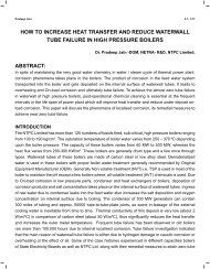
Many processes require continuous monitoring of the thickness of a product to provide feedback<br />
to control product characteristics. Product thickness may change due to production line wear or to<br />
changes in the consistency and integrity of the feedstock. Typically you're measuring either piece<br />
parts (Figure 1A), or a sheet type of product as shown in Figure 1B. As production line speeds<br />
increase so does the cost of scrap product—you need to catch any thickness change quickly or<br />
provide active feedback to the production line.<br />
http://www.sensorsmag.com/sensors/motion-velocity-displ...ess-measurements-using-laser-triangulation-7050?print=1 (1 of 12)23/04/2010 10:56:30 AM
<strong>Thickness</strong> <strong>Measurements</strong> <strong>Using</strong> <strong>Laser</strong> <strong>Triangulation</strong> | <strong>Sensors</strong> Magazine<br />
Figure 1. <strong>Laser</strong> sensors can measure the thickness of piece parts (A) or a continuous feed (B)<br />
Why Use <strong>Laser</strong> <strong>Sensors</strong>?<br />
As optoelectronics have improved, so have laser displacement sensors, with increased<br />
resolution, accuracy, linearity, and frequency response. The introduction of CMOS optical<br />
displacement sensors has resulted in lower-cost laser displacement sensors that are starting to<br />
rival other traditional displacement sensors such as eddy current and capacitive sensors. <strong>Laser</strong><br />
displacement sensors (see sidebar "The MTI Microtrak II") are also suited to make difficult<br />
thickness measurements. For example, they are not bothered by humidity or water vapor that can<br />
affect capacitive sensors; they are relatively immune to temperature and acoustic variations that<br />
can affect ultrasonic sensors; and they are not sensitive to target conductivity or magnetization<br />
that affects eddy current sensors. <strong>Laser</strong> displacement sensors can measure equally well to just<br />
http://www.sensorsmag.com/sensors/motion-velocity-displ...ess-measurements-using-laser-triangulation-7050?print=1 (2 of 12)23/04/2010 10:56:30 AM
<strong>Thickness</strong> <strong>Measurements</strong> <strong>Using</strong> <strong>Laser</strong> <strong>Triangulation</strong> | <strong>Sensors</strong> Magazine<br />
about any target material and typically have operating ranges of several inches, with standoff<br />
distances ranging from several inches to several feet; capacitive and eddy current probes<br />
typically have operating ranges of tenths of inches. Large standoffs help keep the sensors out of<br />
harm's way when something goes wrong with the process line as well as allowing for relatively<br />
large changes in thickness without the need to reset the sensor for different production runs.<br />
Recently, laser displacement sensors have begun to shed their bulky controllers, integrating their<br />
control electronics within the sensing head.<br />
Computing the <strong>Thickness</strong><br />
The standard thickness equation is shown<br />
in Equation 1:<br />
where:<br />
G = total gap<br />
T = target thickness<br />
gap from sensor 1 to<br />
A =<br />
target<br />
gap from sensor 2 to<br />
B =<br />
target<br />
(1)<br />
To solve for target thickness (Figure 2) we<br />
can rewrite the equation, solving for T. This<br />
isn't a serious issue when using absolute<br />
sensors such as capacitance probes; you<br />
can run the voltage outputs into a summing<br />
amplifier that inverts the output. When<br />
using sensors that have a relative<br />
calibration with bipolar outputs, as shown in<br />
Figure 3, it is slightly more difficult to Figure 2. Measuring thickness<br />
compute the thickness. For example MTI's<br />
Microtrak II controller outputs a bipolar ± 5 V voltage centered about the specified standoff<br />
distance. You can't run the analog outputs into an inverting summing amplifier because the<br />
Microtrak's output voltage polarity changes, resulting in errors when you pass through the center<br />
of the range. Mathematically the thickness equation looks like Equation 2:<br />
(2)<br />
http://www.sensorsmag.com/sensors/motion-velocity-displ...ess-measurements-using-laser-triangulation-7050?print=1 (3 of 12)23/04/2010 10:56:30 AM
<strong>Thickness</strong> <strong>Measurements</strong> <strong>Using</strong> <strong>Laser</strong> <strong>Triangulation</strong> | <strong>Sensors</strong> Magazine<br />
Figure 3. <strong>Using</strong> sensors that have a relative calibration and bipolar outputs<br />
Practically speaking, most users ignore the standoffs and treat them as one big DC offset and<br />
only deal with the active range of the heads once they're set up. For example, we could sum 5<br />
VDC with each of the heads to make the controller output always positive (0–10V unipolar) and<br />
then sum the two outputs, invert the output, and run it into a voltmeter. After setup, place a target<br />
of known thickness—the golden target—between the lasers and then zero the meter. All readings<br />
http://www.sensorsmag.com/sensors/motion-velocity-displ...ess-measurements-using-laser-triangulation-7050?print=1 (4 of 12)23/04/2010 10:56:30 AM
<strong>Thickness</strong> <strong>Measurements</strong> <strong>Using</strong> <strong>Laser</strong> <strong>Triangulation</strong> | <strong>Sensors</strong> Magazine<br />
are now relative to the target with known thickness. Multiply the voltmeter's voltage by the<br />
sensitivity factor of the laser heads to get the change in thickness relative to the golden target.<br />
Displaying the <strong>Thickness</strong> Data<br />
There are many ways to display the thickness data depending on your budget and how elaborate<br />
your measurement setup is. One simple method that can be used for one to three slow-speed<br />
thickness channels (with two heads per thickness channel) is to connect stand-alone measuring<br />
heads to a laptop computer through an RS-485 to USB converter. One converter can handle from<br />
one to six heads to provide up to three thickness points. The heads all tie in parallel to the same<br />
USB converter and the heads are addressed individually by the display software (Figure 4).<br />
Figure 4. The display shows a real-time plot of the individual head's displacement and the resulting<br />
thickness measurement<br />
For those who do not like programming or don't have the time, another solution is to use a<br />
http://www.sensorsmag.com/sensors/motion-velocity-displ...ess-measurements-using-laser-triangulation-7050?print=1 (5 of 12)23/04/2010 10:56:30 AM
<strong>Thickness</strong> <strong>Measurements</strong> <strong>Using</strong> <strong>Laser</strong> <strong>Triangulation</strong> | <strong>Sensors</strong> Magazine<br />
precision analog summing amplifier with two laser heads, a digital panel meter (Figure 5), and a<br />
switch. This allows you to select between individual heads during setup and then to select the<br />
thickness module's output when running. Typically, once the heads are set up you insert a target<br />
of known thickness and adjust the thickness module to 0 V. Many panel meters also have one or<br />
more built-in alarm contacts that allow triggering an alarm event based on voltage set points.<br />
http://www.sensorsmag.com/sensors/motion-velocity-displ...ess-measurements-using-laser-triangulation-7050?print=1 (6 of 12)23/04/2010 10:56:30 AM
<strong>Thickness</strong> <strong>Measurements</strong> <strong>Using</strong> <strong>Laser</strong> <strong>Triangulation</strong> | <strong>Sensors</strong> Magazine<br />
Figure 5. <strong>Using</strong> a precision summing amplifier, two laser heads, and a panel<br />
meter, you can display thickness data<br />
High-speed systems for industrial control and alarming require higher speed communications.<br />
Ethernet connections allow communication speeds of up to 100 Mbps and there are a number of<br />
off-the-shelf analog to digital converter (ADC) components available to build such a system.<br />
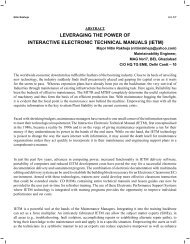
In the system shown in Figure 6, a precision MTI thickness module is used to combine the<br />
analog outputs from the laser heads and to provide a high-speed, real-time analog thickness<br />
signal. Advantech ADAM 6017 DA modules convert the thickness and individual displacement<br />
readings into high-speed Ethernet packets that are read by an off-the-shelf HMI. Advantech<br />
ADAMView software ties the whole system together. An extra ADAM module used in conjunction<br />
with a proximity sensor alerts the system that a target is present if discreet sheets are being<br />
measured. A standard multiport Ethernet switch ties all the Ethernet cables together.<br />
http://www.sensorsmag.com/sensors/motion-velocity-displ...ess-measurements-using-laser-triangulation-7050?print=1 (7 of 12)23/04/2010 10:56:30 AM
<strong>Thickness</strong> <strong>Measurements</strong> <strong>Using</strong> <strong>Laser</strong> <strong>Triangulation</strong> | <strong>Sensors</strong> Magazine<br />
Figure 6. Coupling laser sensors with DA modules and an HMI provides high-speed analog<br />
thickness data<br />
http://www.sensorsmag.com/sensors/motion-velocity-displ...ess-measurements-using-laser-triangulation-7050?print=1 (8 of 12)23/04/2010 10:56:30 AM
<strong>Thickness</strong> <strong>Measurements</strong> <strong>Using</strong> <strong>Laser</strong> <strong>Triangulation</strong> | <strong>Sensors</strong> Magazine<br />
Why Use Synchronized <strong>Laser</strong>s?<br />
When measuring thickness, the lasers must sample the<br />
thickness at the exact same instant or else an error will be<br />
introduced. The size of the error is dependent on several<br />
external parameters such as target speed, vibration, and the<br />
nature of the surface of the target material. Even though slow<br />
process speeds may be involved, high-frequency vibrations can<br />
contribute fairly significant errors if the heads sample the target<br />
even tenths of milliseconds apart. Let's say that you have a<br />
sheet of aluminum with 60 Hz vibration present from a conveyor<br />
motor. If the vibration was 0.002 in. and the laser heads<br />
sampling was delayed by 0.008 s (125 Hz sampling) then you<br />
could see a thickness variation of up to .004 inch. MTI's lasers<br />
share control signals that ensure synchronous sampling occurs<br />
within 0.00001 s. In the same application the thickness variation<br />
due to vibration would be
<strong>Thickness</strong> <strong>Measurements</strong> <strong>Using</strong> <strong>Laser</strong> <strong>Triangulation</strong> | <strong>Sensors</strong> Magazine<br />
Figure 8. Proper design concept where both sides of the sensor supports are fixed to prevent<br />
unwanted vibration. One side can be made removable so the structure is easily disassembled for<br />
access or service<br />
<strong>Laser</strong> Adjustment<br />
One of the simplest ways to adjust the lasers is first to adjust their standoff to the target for<br />
nominal center-of-the-range standoff distance. Remove the target and replace it with a flat sheet<br />
of translucent white paper so the two laser spots may be observed simultaneously. The sheet of<br />
paper should be at the same location as the target material would be. Next, adjust the heads such<br />
that the spots remain superimposed upon each other as the paper is moved back and forth<br />
between the range of the lasers in a perpendicular direction. As you move the paper back and<br />
forth, perpendicular to the heads, you'll see one spot gets larger while the other gets smaller. This<br />
is because the laser beams are focused at the nominal standoff distance. As you move away<br />
from the nominal standoff, the beams expand. Once you have the laser adjusted for continuous<br />
concentric coaxial alignment throughout the range (Figure 9) be sure to lock the adjustment<br />
screws down or cap them to prevent unauthorized users from tampering with them.<br />
http://www.sensorsmag.com/sensors/motion-velocity-displ...ess-measurements-using-laser-triangulation-7050?print=1 (10 of 12)23/04/2010 10:56:30 AM
<strong>Thickness</strong> <strong>Measurements</strong> <strong>Using</strong> <strong>Laser</strong> <strong>Triangulation</strong> | <strong>Sensors</strong> Magazine<br />
Figure 9. A set up to adjust the lasers<br />
System or <strong>Thickness</strong> Calibration<br />
Although the individual laser heads are already calibrated, you'll have to calibrate the assembled<br />
system for thickness. Place a target of known thickness in between the lasers and tare the<br />
system to zero or set the readout device to read the actual thickness of the known target. The<br />
system function for thickness is <strong>Thickness</strong> = Total gap – (laser gap 1 + laser gap 2).<br />
Overall System Accuracy<br />
Assuming you haven't introduced any additional error with poor fixturing, the overall measurement<br />
uncertainty will be 2*max linearity error + 0.5 the peak-to-peak (pk-pk) noise at the bandwidth<br />
selected because you're using two heads. For a head linearity of ± 0.05% F.S. where F.S. = 10<br />
mm, if the dynamic noise for the same heads is 3 µm pk-pk then the total measurement error<br />
could be as high as 10 µm + 1.5 µm = 11.5 µm.<br />
Fixture vibration and surface finish effects will also add to this uncertainty, and could easily<br />
increase the uncertainty to 23 µm. Most laser head dynamic noise or uncertainty is given at a<br />
specific bandwidth and when measuring to white paper. Actual targets can easily cause larger pkpk<br />
noise values. Averaging techniques such as low-pass filtering or a digital moving average can<br />
help reduce uncertainty due to surface finish effects and head noise and can sometimes make an<br />
impossibly noisy measurement both possible and statistically useful.<br />
Closing Thoughts<br />
The above are just a few ideas to help make your thickness setup as foolproof as possible.<br />
Following these guidelines will help ensure the highest accuracy and repeatability of your<br />
thickness data.<br />
ABOUT THE AUTHOR<br />
Don Welch is Director for New Business Development at MTI Instruments, Albany, NY. He can<br />
be reached at 518-218-2503, dwelch@mtiinstruments.com.<br />
http://www.sensorsmag.com/sensors/motion-velocity-displ...ess-measurements-using-laser-triangulation-7050?print=1 (11 of 12)23/04/2010 10:56:30 AM
<strong>Thickness</strong> <strong>Measurements</strong> <strong>Using</strong> <strong>Laser</strong> <strong>Triangulation</strong> | <strong>Sensors</strong> Magazine<br />
The MTI Microtrak II<br />
MTI's Microtrak II stand-alone laser sensing devices have an integrated CMOS sensor within<br />
the head and a built-in processor for data averaging and filtering. Both sensors communicate<br />
with each other to synchronize their data sampling, which ensures the correct thickness reading<br />
and eliminates the need for a separate controller. The system provides both analog (0–10V or<br />
4–20 mA) and digital outputs (RS-485 binary format). Either can be used to determine<br />
thickness, but analog is preferred for very high frequency (>100 Hz) response.<br />
The sensors provide high-speed resolution within a combined accuracy of ±0.1% of the<br />
measurement range, a data-sampling rate of 40 kHz, a bandwidth of 20 kHz, and standoff<br />
distances from 25–300 mm. A dynamic laser feedback loop allows accurate measurement<br />
without regard to color, ambient light changes, variations in object reflectivity, speed,<br />
temperature of material, or general plant environmental conditions. The feedback loop allows<br />
the sensor to make virtually error-free measurements with high reliability and repeatability up to<br />
40,000 times per second within a defined spot, while operating from a single 12–30VDC supply.<br />
The thickness system has measurement ranges of 2–200 mm, depending on the head<br />
selection, and can operate at temperatures from 0°C–40°C. The sensor is enclosed in a sealed<br />
aluminum housing to protect it from moisture and dust. An external air purge provision can be<br />
provided to keep the optics dirt and dust free.<br />
About the Author: Don Welch<br />
●<br />
●<br />
About Don Welch<br />
Articles by Don Welch<br />
Bookmark it: digg propeller del.icio.us technorati yahoo facebook<br />
http://www.sensorsmag.com/sensors/motion-velocity-displ...ess-measurements-using-laser-triangulation-7050?print=1 (12 of 12)23/04/2010 10:56:30 AM