Installation Guide - Igus
Installation Guide - Igus
Installation Guide - Igus

You also want an ePaper? Increase the reach of your titles
YUMPU automatically turns print PDFs into web optimized ePapers that Google loves.
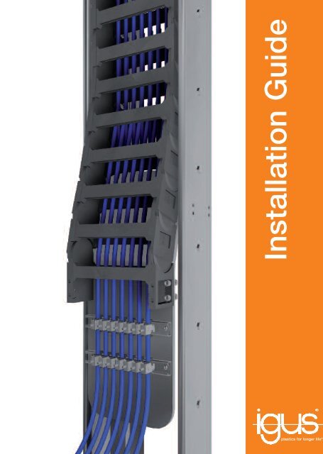
<strong>Installation</strong> <strong>Guide</strong><br />
plastics for longer life ®
igus ® E-ChainSystem ® - <strong>Installation</strong> <strong>Guide</strong><br />
E-Chain ®<br />
<strong>Guide</strong> trough<br />
Fixed point<br />
Cable reserve<br />
Support structure<br />
<strong>Guide</strong> trough<br />
Moving end<br />
E-Chain ®<br />
Support structure<br />
Fixed point<br />
Moving end<br />
2
igus ® E-ChainSystem ® - <strong>Installation</strong> <strong>Guide</strong><br />
Endposition I<br />
Fixed point<br />
Endposition II<br />
Moving end<br />
<strong>Guide</strong> trough with glide bar<br />
<strong>Guide</strong> trough without glide bar<br />
Total length of <strong>Guide</strong> trough<br />
Fixed point<br />
<strong>Guide</strong> trough with glide bar<br />
<strong>Guide</strong> trough without glide bar<br />
max. 3mm<br />
4
Check <strong>Installation</strong> Space<br />
Use igus ® System Drawings<br />
Space requirement for E-ChainSystem ®<br />
<strong>Installation</strong> has to be done according to igus ® system drawings<br />
L<br />
h<br />
b<br />
E-Chain ® has to be<br />
free movable along<br />
the entire travel length.<br />
Other obstacles or<br />
crane parts must not<br />
disturb operation area!<br />
wrong!<br />
L<br />
h<br />
b<br />
6
Support Structure for Guiding Trough<br />
L-Profile<br />
oblong hole<br />
drillpattern c-profile<br />
Support structure has to be aligned and level<br />
wrong!<br />
x ± 5<br />
z = 2000 ± 3<br />
L-profile<br />
Level the support structure<br />
y ± 5<br />
x ± 5<br />
right<br />
wrong!<br />
wrong!<br />
Crane rail and support<br />
structure have to be<br />
aligned.<br />
Center line<br />
Crane rail = reference<br />
Level the L-profile<br />
wrong!<br />
wrong!<br />
x ± 5<br />
Crane rail<br />
Center line<br />
Check support strukture before trough<br />
installation. Necessary reworks to be<br />
corrected before next installation step.<br />
8
Guiding Trough <strong>Installation</strong><br />
Prepare a spacer tool, to adjust the inner trough width.<br />
E-Chain ® outer width = Ba<br />
No gap = wrong!<br />
Ba<br />
No gap = wear on chain links. E-Chain ® is blocked.<br />
2 +1 mm 2 +1 mm<br />
Big gap = wrong!<br />
Ba +4 +2<br />
Ba + 4 = L<br />
L<br />
L/2<br />
Spacer tool<br />
Big gap = wear on chain links and cross bar.<br />
10
E-Chain ® Pre-Assembly<br />
Check part no. on E-Chain ® , before assembly.<br />
For example: 5050C- 4040C- Series<br />
Chain s number 5050C.30.300.0<br />
5050C Series Number<br />
30 Width<br />
300 Radius of chain<br />
0 Colour<br />
E-Chain ® assembly<br />
Lay the fixed point (part 3) into the trough and assemble part 2<br />
until you reach the mounting end.<br />
part 3 part 2 part 1<br />
Fixed point (KMA+ 11.Links)<br />
E-Chain ® parts (11links each)<br />
Moving end (rest length + KMA)<br />
Signed with orange flag<br />
Three links turned<br />
12
E-Chain ® Pre-Assembly<br />
Make sure that fixed point position is according to igus ®<br />
drawings, relative to the travel stroke.<br />
Lay thee preassembled E-Chain ® into the guiding tough.<br />
Fixed point<br />
Moving end<br />
Turned links<br />
Details see igus ® long travel drawing<br />
Red flag<br />
Fixed point<br />
Moving end<br />
Check fixed point position<br />
relative to the travel stroke.<br />
14
Pull Cables Into E-Chain ®<br />
Cable arrangement has to be according to igus ® interior<br />
shelving drawing<br />
Possible instalation:<br />
Pull cables into E-Chain ®<br />
Possible faults:<br />
Corkscrew or<br />
Cable damage<br />
right<br />
wrong!<br />
wrong!<br />
All crossbars snapped in? Any broken parts?<br />
right<br />
wrong!<br />
Alternative instalation:<br />
Open the crossbars, lay the cables in the E-Chain ® and close it.<br />
Check the interior separation of E-Chain ® .<br />
All seperators plumb and tight?<br />
right<br />
wrong!<br />
16
Attach E-Chain ®<br />
Level Moving End<br />
Leave a spare cable loop for cable adjustment at fixed point<br />
and moving end.<br />
Moving end has to be installed<br />
according to system drawing.<br />
Support plate has to be in level!<br />
Height according to drawing.<br />
max. 3mm<br />
Spare cable min 0,5m<br />
h<br />
h<br />
Make shure that fixed point is at correct position and fix it<br />
with allan screws (DIN 912 / EN ISO 7462).<br />
h<br />
h<br />
wrong!<br />
for E4.80/5050C h= 242mm +10<br />
for E4.56/4040C/400 h= 266mm +10<br />
18
Installl Moving End<br />
Adjust Cables<br />
Flip chain radius, move it to the moving arm and fix it with<br />
allan screws (DIN 912 / EN ISO 7462).<br />
Correct cable adjustment<br />
Cable has to run slightly outside the centerline<br />
wrong!<br />
wrong!<br />
wrong!<br />
Cable too tight<br />
Cable too loose<br />
20
Install Strain Relief<br />
Check <strong>Installation</strong> Before First Movement<br />
Install strain relief clambs at moving end and fixed point.<br />
Swing strain relief clamps in the c-rail and<br />
theighten the screw.<br />
All screws in place and fixed<br />
with toque spanner<br />
Moving end height and<br />
E-Chain ® fixation OK?<br />
Any obstacles /<br />
tools in the guiding trough?<br />
All strain relief clamps<br />
installed<br />
Check height<br />
wrong!<br />
Cable arrangement OK?<br />
Move the E-Chain ® slow and carefull to both<br />
end positions and check cable arrangement.<br />
Doublecheck after a few test cycles.<br />
22
MAT0071536.2 Issue 02/2010