Introduction to CIM - IGNOU
Introduction to CIM - IGNOU
Introduction to CIM - IGNOU

You also want an ePaper? Increase the reach of your titles
YUMPU automatically turns print PDFs into web optimized ePapers that Google loves.
UNIT 1 INTRODUCTION TO <strong>CIM</strong><br />
<strong>Introduction</strong> <strong>to</strong> <strong>CIM</strong><br />
Structure<br />
1.1 <strong>Introduction</strong><br />
Objectives<br />
1.2 Enterprisewide Integration of <strong>CIM</strong><br />
1.3 Scope of Computer Integrated Manufacturing<br />
1.4 Operational Flow within CAD/CAM<br />
1.5 CAM, CAD/CAM and <strong>CIM</strong><br />
1.5.1 Computer Aided Manufacturing<br />
1.5.2 CAD/CAM<br />
1.5.3 Computer Integrated Manufacturing<br />
1.6 Integration Approaches of CAD/CAM Preliminary Status<br />
1.7 Summary<br />
1.8 Key Words<br />
1.1 INTRODUCTION<br />
Initially, machine <strong>to</strong>ol au<strong>to</strong>mation started with the development of numerical control in<br />
1950s. In less than 50 years, it is amazing that <strong>to</strong>day‟s manufacturing plants are<br />
completely au<strong>to</strong>mated. However, establishment of these plants gave relatively a few<br />
varieties of product. At first we define what do we mean by a manufacturing plant? Here,<br />
we are considering a several categories of manufacturing (or production) for the various<br />
manufacturing plants. Manufacturing can be considered in three broad areas:<br />
(i)<br />
(ii)<br />
(iii)<br />
continuous process production,<br />
mass production, and<br />
job-shop production.<br />
Among these three, mass production and job-shop production can be categorized as<br />
discrete- item production.<br />
Continuous Process Production<br />
Such type of product flows continuously in the manufacturing system, e.g.<br />
petroleum, cement, steel rolling, petrochemical and paper production etc.<br />
Equipment used here are only applicable for small group of similar products.<br />
Mass Production<br />
It includes the production of discrete unit at very high rate of speed. Discrete<br />
item production is used for goods such as au<strong>to</strong>mobiles, refrigera<strong>to</strong>rs, televisions,<br />
electronic component and so on. Mass production contains the character of<br />
continuous process production for discrete products. That‟s why; mass<br />
production has realized enormous benefits from au<strong>to</strong>mation and mechanization.<br />
Job Shop Production<br />
A manufacturing facility that produces a large number of different discrete items<br />
and requires different sequences among the production equipments is called job<br />
shop. Scheduling and routine problems are the essential features of job shop. As<br />
a result au<strong>to</strong>mation has at best been restricted <strong>to</strong> individual component of job<br />
shop. But there have been few attempts in the field of <strong>to</strong>tal au<strong>to</strong>mation.<br />
5
Fundamentals of <strong>CIM</strong><br />
Physical components of an au<strong>to</strong>mated manufacturing system do not include continuous<br />
flow process as it only consists of a small percentage of manufacturing system. Mass<br />
production of discrete items is included in this category, where segments of production<br />
line are largely au<strong>to</strong>mated but not the entire line. Job shop facilities have used au<strong>to</strong>mated<br />
machines, but transfer of work among these machines is a difficult task. Apart from<br />
some physical equipment needed, a major component of the au<strong>to</strong>mated information that<br />
needs <strong>to</strong> be made available <strong>to</strong> the manufacturing operation must come from product<br />
design. This allows a plant <strong>to</strong> be au<strong>to</strong>mated and integrated. However, manufacturing is<br />
more concerned with process design rather than product design.<br />
The characteristic of present world market include higher competition, short product life<br />
cycle, greater product diversity, fragmented market, variety and complexity, and smaller<br />
batch sizes <strong>to</strong> satisfy a variety of cus<strong>to</strong>mer profile. Furthermore, non price fac<strong>to</strong>rs such<br />
as quality of product design, innovation and delivery services are the preliminary<br />
determinant for the success of product. In <strong>to</strong>day‟s global arena, <strong>to</strong> achieve these<br />
requirements manufacturing company needs <strong>to</strong> be flexible, adaptable and responsive <strong>to</strong><br />
changes and be able <strong>to</strong> produce a variety of products in short time and at lower cost.<br />
These issues attract manufacturing industries <strong>to</strong> search for some advanced technology,<br />
which can overcome these difficulties. Computer integrated manufacturing (<strong>CIM</strong>), which<br />
emerged in 1970, was the outcome of this protracted search.<br />
<strong>CIM</strong> involves a fundamental strategy of integrating manufacturing facilities and systems<br />
in an enterprise through the computer and its peripheral. <strong>CIM</strong> can be defined in different<br />
ways depending upon its application. <strong>CIM</strong> involves integration of advanced technologies<br />
in various functional units of an enterprise, in an effective manner <strong>to</strong> achieve the success<br />
of the manufacturing industries. A deep knowledge and understanding of all the<br />
technology is required for an effective integration. At first integration of advanced<br />
manufacturing technology (AMT) is required <strong>to</strong> get success in the application of <strong>CIM</strong>.<br />
Computers act as a subordinate <strong>to</strong> the technologies. Computers help, organize, and<br />
res<strong>to</strong>re information in order <strong>to</strong> achieve high accuracy and speed. Their basic aim is <strong>to</strong><br />
achieve the goals of the objectives within limited available capital. Traditionally, all the<br />
efforts were focused on achieving single goal <strong>to</strong> improve the effectiveness and<br />
competitiveness of the organization. But they failed because they didn‟t satisfy the<br />
overall objectives of the manufacturing companies. Hence, a multiple goal selection or<br />
mult- criteria optimization is proposed <strong>to</strong> make the <strong>CIM</strong> an effective <strong>to</strong>ol <strong>to</strong> improve the<br />
economy of the company. The new approach should be developed for improving the<br />
existing multi-criteria optimization mechanism, so that <strong>CIM</strong> can be realized globally. In<br />
addition, global integration approach should be applied <strong>to</strong> make globally distributed<br />
company as a single entity. This concept is applied <strong>to</strong> make virtual <strong>CIM</strong> more effective<br />
and hence helps in meeting the present global economic circumstances using intelligent<br />
manufacturing. Therefore, manufacturing technology should be blended with<br />
intelligence. This will help manufacturing enterprise <strong>to</strong> produce better quality. It will<br />
also facilitate the manufacturing equipments <strong>to</strong> solve problems posed during normal<br />
course of the operations.<br />
Computer technology is the necessary input <strong>to</strong> implement au<strong>to</strong>mation in manufacturing<br />
system. The term <strong>CIM</strong> denotes the widespread use of computer systems <strong>to</strong> design the<br />
product, <strong>to</strong> plan the production, control the operation, and perform the business related<br />
functions required in the manufacturing firm. True <strong>CIM</strong> includes integration of these<br />
functions in the system that operates throughout the enterprise. Other words are used <strong>to</strong><br />
identify specific element of the <strong>CIM</strong> system. For example, computer aided design (CAD)<br />
denotes the use of computer system <strong>to</strong> support the product design system. Computer<br />
aided manufacturing (CAM) denotes the use of computer system <strong>to</strong> perform the<br />
functions related <strong>to</strong> manufacturing engineering, such as process planning and<br />
numerically controlled (NC) part programming. Some computer system performs the<br />
CAD and CAM, and so the term CAD/CAM is used <strong>to</strong> indicate the integration of the two<br />
systems in<strong>to</strong> one. In addition <strong>to</strong> CAD/CAM, <strong>CIM</strong> also includes the firm business<br />
function that are related <strong>to</strong> manufacturing.<br />
6
Benefits of <strong>CIM</strong><br />
<strong>CIM</strong> plays a vital role in the economy of the manufacturing system or enterprise.<br />
The benefits of <strong>CIM</strong> are indicated as follows:<br />
(i)<br />
(ii)<br />
(iii)<br />
(iv)<br />
(v)<br />
(vi)<br />
(vii)<br />
(viii)<br />
(ix)<br />
(x)<br />
(xi)<br />
(xii)<br />
(xiii)<br />
(xiv)<br />
Objectives<br />
Products quality improvement.<br />
Shorter time in launching new product in the market.<br />
Flow time minimized.<br />
Inven<strong>to</strong>ry level reduced.<br />
Competitiveness increases.<br />
Improved scheduling performance.<br />
Shorter vendor lead time.<br />
Improved cus<strong>to</strong>mer service.<br />
Increase in flexibility and responsiveness.<br />
Total cost minimized.<br />
Long term profitability increases.<br />
Cus<strong>to</strong>mers lead time minimized.<br />
Manufacturing productivity increases.<br />
Work in process inven<strong>to</strong>ry decreases.<br />
After studying this unit, you should be able <strong>to</strong><br />
<br />
<br />
<br />
<br />
<br />
<br />
describe the fundamental concepts of <strong>CIM</strong>,<br />
explain enterprisewide integration of <strong>CIM</strong> and concept of <strong>CIM</strong> wheel,<br />
differentiate between CAM, CAD/CAM, and <strong>CIM</strong>,<br />
know the scope of <strong>CIM</strong>,<br />
discuss operations flow within CAD/CAM, and<br />
know the different approaches for integration of CAD/CAM.<br />
<strong>Introduction</strong> <strong>to</strong> <strong>CIM</strong><br />
1.2 ENTERPRISEWIDE INTEGRATION OF <strong>CIM</strong><br />
Dr. J. Harring<strong>to</strong>n, Jr. introduces the concept of Computer Integrated Manufacturing<br />
(<strong>CIM</strong>) in the year 1973. He demonstrated the integration approach <strong>to</strong> an enterprise.<br />
Keeping in mind the current and future market trend for cus<strong>to</strong>mized product and in order<br />
<strong>to</strong> stand in the competitive edge over long time, virtual organizations are used as an<br />
important weapon. Hence, in order <strong>to</strong> achieve corporate goal and objectives, integration<br />
approach is required for cus<strong>to</strong>mer as well as suppliers. <strong>CIM</strong>, in general, may be defined<br />
as follows :<br />
<strong>CIM</strong> is the integration of <strong>to</strong>tal manufacturing enterprise through the use of integrated<br />
system and data communication mixed with new managerial philosophies which results<br />
in the improvement of personnel or organizational efficiencies.<br />
From the definition mentioned above, the ultimate goal of <strong>CIM</strong> is the integration of all<br />
the enterprise operation and activities around a common data collection. In this context,<br />
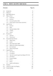
society of manufacturing engineers (SME) introduces the <strong>CIM</strong> wheel, which gives a<br />
clear cut picture of relationship among all parts of the enterprise. It shows three layered<br />
integration structure of an enterprise as given in Figure 1.1. Outer layer constitutes of<br />
general management which includes marketing, strategic planning, finance,<br />
manufacturing management and human resource management. The middle layer consists<br />
7
Fundamentals of <strong>CIM</strong><br />
of three process segments: product and process determination, manufacturing planning<br />
and control, and fac<strong>to</strong>ry au<strong>to</strong>mation. These process segments represent all the activities<br />
in the design and manufacturing phase of a product life cycle taking the product from<br />
concept <strong>to</strong> assembly. The center of wheel represents the third layer which include<br />
information resources management and common database.<br />
Figure 1.1 : The SME <strong>CIM</strong> Wheel<br />
(© 1985, Society of Manfacturing Engineers, Dearborn, Mi 48121, Which Focuses on the Cus<strong>to</strong>mer<br />
Rather than the Database<br />
SAQ 1<br />
(a)<br />
(b)<br />
(c)<br />
What are the different basis of classifying production system according <strong>to</strong><br />
the quality and variety of product?<br />
What are the potential benefits of <strong>CIM</strong>?<br />
Discuss the concept of <strong>CIM</strong> wheel and explain the importance of integrating<br />
the enterprise included therein?<br />
1.3 THE SCOPE OF COMPUTER-INTEGRATED<br />
MANUFACTURING<br />
When all of the activities of the modern manufacturing plants are considered as a whole,<br />
it is impossible <strong>to</strong> think that a small portion might be au<strong>to</strong>mated, let alone trying <strong>to</strong><br />
envisage au<strong>to</strong>mation of the whole. In systems approach, a large and complex system with<br />
interacting components are analyzed and improved. Anyone vested with the<br />
8
esponsibility of implementation of au<strong>to</strong>mation for complex system is advised <strong>to</strong><br />
implement a technique similar <strong>to</strong> the traditional systems approach.<br />
Following steps are involved in the systems approach :<br />
(a)<br />
(b)<br />
(c)<br />
(d)<br />
(e)<br />
(f)<br />
(g)<br />
Objectives of the system are determined.<br />
Structuring the system and set definable system boundaries.<br />
Significant components for a system are determined.<br />
A detailed study of the components is carried out keeping in view the<br />
overall integration of the system.<br />
Analyzed components are synthesized in<strong>to</strong> the system.<br />
On the basis of the performance criteria, predetermined system is evaluated.<br />
For continuous improvement, Step „b‟ <strong>to</strong> Step „f‟ are constantly repeated.<br />
No task, however small, should be tackled without knowledge of the task objective. This<br />
is the key ingredient which, when lacking, causes members of the same team <strong>to</strong> pull in<br />
different directions. In considering fac<strong>to</strong>ry au<strong>to</strong>mation, there could be many possible<br />
objectives. One might be <strong>to</strong> improve the performance of a specific process. Boundary<br />
conditions would then be limited <strong>to</strong> that process (as well as other processes that might be<br />
affected by increased output, such as material supply and assembly after production).<br />
Another objective might be <strong>to</strong> minimize cost in a segment of the operation, while a third<br />
might be profit maximization; obviously it is rare that such multiple objectives can all be<br />
optimized, even though politicians seem <strong>to</strong> think so when it comes close <strong>to</strong> election day.<br />
When considering moving <strong>to</strong> a computer integrated manufacturing operation, the<br />
objective would probably be related <strong>to</strong> being competitive, a problem that manufacturing<br />
plants are having at the micro level and a situation that is almost catastrophic for the<br />
nation at the macro level.<br />
Setting system boundaries for a <strong>CIM</strong> project might at first appear <strong>to</strong> be concerned only<br />
with the engineering design and actual manufacture of the products. While the<br />
integration of these two components is a major task which is not satisfied in most of the<br />
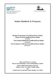
facilities, <strong>CIM</strong> goes beyond these activities. Figure 1.2 shows graphically what is<br />
involved in computer integrated manufacturing.<br />
As far as plant itself is concerned, there are five major components:<br />
Computer Aided Engineering (CAE)<br />
CAE encompasses CAD, NC programming, <strong>to</strong>ol and fixture design, quality<br />
control (QC) planning, and process planning. This later areas that ties CAD and<br />
CAM <strong>to</strong>gether and when au<strong>to</strong>mated is called computer aided process planning<br />
(CAPP).<br />
Operations Management<br />
Operations management governs the acquisition of all materials needed for<br />
product manufacture; since a cost effective system is required, it is manda<strong>to</strong>ry <strong>to</strong><br />
include cost accounting. Production planning and control is required <strong>to</strong> ensure<br />
that parts are routed in an efficient manner <strong>to</strong> keep equipment busy as well as <strong>to</strong><br />
ensure that cus<strong>to</strong>mers needs are satisfied. Shop floor controls are needed <strong>to</strong> ensure<br />
that production data is available <strong>to</strong> production planning and control as well as <strong>to</strong><br />
allow planned sequencing <strong>to</strong> be effected on the shop floor.<br />
<strong>Introduction</strong> <strong>to</strong> <strong>CIM</strong><br />
9
Cost accounting<br />
Purchasing<br />
Production planning & control<br />
Shop-floor control<br />
contro<br />
Planning and measurement<br />
External public or<br />
private networks<br />
CAD<br />
Computer-aided<br />
engineering<br />
Analysis<br />
Product & process engineering<br />
NC<br />
Programming<br />
Mold / <strong>to</strong>ol<br />
Design<br />
Market information<br />
Cus<strong>to</strong>mer order<br />
Data<br />
Order entry<br />
Data<br />
Data<br />
Data<br />
Process planning<br />
QC planning<br />
Printed circuit<br />
boards<br />
CNC machining<br />
and fabrication (DNC)<br />
Plastic<br />
moulding<br />
Data management &<br />
communications<br />
Internal networking services<br />
Assembly robots<br />
Material handling<br />
robots<br />
Computer-aided<br />
manufacturing<br />
Parts manufacturing and<br />
test<br />
Data<br />
Computer-aided<br />
manufacturing<br />
Finally assembly<br />
Welding / painting<br />
robots<br />
Materials<br />
Materials<br />
Programmable<br />
Controls<br />
Vendor parts<br />
Materials<br />
Intelligent warehouse<br />
system (s)<br />
Master s<strong>to</strong>rage & handling<br />
Finished goods<br />
Shipping<br />
Incoming parts<br />
inspection<br />
Finished goods<br />
inven<strong>to</strong>ry<br />
In-process inven<strong>to</strong>ry<br />
Au<strong>to</strong>mated carriers<br />
Figure 1.2 : Structure of <strong>CIM</strong> (from Ref.8, Courtesy of Production Engineering)<br />
10
Computer Aided Manufacturing – Manufacturing and Test<br />
Parts have <strong>to</strong> be manufactured and tested. A major point is made in Figure 1.2 that<br />
should be exemplified at this point. Many people think that computer aided<br />
manufacturing is for chip-cutting part only – those parts that are machined in same<br />
fashion. It is not true, as it cannot be stressed <strong>to</strong>o forcefully. Several activities<br />
related <strong>to</strong> manufacturing of PCBs (Printed Circuit Board), controlling nontraditional<br />
machines (Electrical Discharge Machine, Electrochemical Machines<br />
etc.) and various precision operations have been using the salient features of<br />
CAM.<br />
Computer Aided Manufacturing – Assembly and Test<br />
Assembly, inspection and packing are the important features of CAM. They play a<br />
major role in the success of the implementation of <strong>CIM</strong> systems.<br />
Intelligent Warehousing<br />
The last component of the <strong>CIM</strong> encompasses au<strong>to</strong>matic s<strong>to</strong>rage and retrieval of<br />
materials and components, and finished goods. It takes in<strong>to</strong> consideration the<br />
incoming materials, products as well as the work-in-progress (WIP).<br />
Finally <strong>to</strong> allow all the components <strong>to</strong> work as an integrated system, we have <strong>to</strong> integrate<br />
the five components with a network system as exemplified by the data management and<br />
communications modules shown in Figure 1.2. Standards have been evolved for this<br />
function, but the information flow in <strong>CIM</strong> is a major problem, which is yet <strong>to</strong> be handled<br />
in an effective manner.<br />
In continuation <strong>to</strong> the systems approach, it is necessary <strong>to</strong> break the system in<strong>to</strong><br />
components for initial analysis. In fact the overall systems approach would be applied <strong>to</strong><br />
the six major components as mentioned before, including the component of data<br />
management and communications. Analysis of the entire system is a difficult and tedious<br />
process as compared <strong>to</strong> the analysis of individual modules. This problem attains a<br />
complex magnitude, when one considers the integration of computer systems for design<br />
and manufacturing.<br />
After the initial analysis of the components, the integration aspect is taken up. It is done<br />
through a networking scheme with a smart database able <strong>to</strong> handle design,<br />
manufacturing, and planning. To achieve this, a hierarchical computer structure must be<br />
employed. The manufacturing database remains at the <strong>to</strong>p of the hierarchy followed by<br />
equipment controlling and data-gathering systems.<br />
We have not yet branched out the <strong>CIM</strong> system. Table 1.1 depicts that fall under the<br />
broad purview of the components discussed so far. In the next section, we will consider<br />
the major functions that relate the areas of CAD, CAM and the production operating<br />
system.<br />
SAQ 2<br />
Discuss the scope of <strong>CIM</strong> in context of business, production and design.<br />
<strong>Introduction</strong> <strong>to</strong> <strong>CIM</strong><br />
11
Industry<br />
Corporation<br />
Plant<br />
Resource<br />
Management<br />
Trend analysis<br />
Resource<br />
availability<br />
Economic<br />
Indica<strong>to</strong>rs<br />
Trend analysis<br />
Facility planning<br />
Strategic planning<br />
Merger/acquisition<br />
Synergistic<br />
product<br />
Production level<br />
Data management<br />
Plant layout<br />
Inven<strong>to</strong>ry<br />
Scheduling<br />
Manpower<br />
utilization<br />
Make/buy decision<br />
Data management<br />
Business Production Design<br />
Economic<br />
Accounting<br />
Projection<br />
Simulations<br />
Cost<br />
tracking<br />
Cus<strong>to</strong>mer<br />
billing<br />
Cus<strong>to</strong>mer<br />
order<br />
Normal<br />
accounting<br />
Make/ buy/<br />
economic<br />
order<br />
quantity<br />
Production<br />
Planning<br />
Capacity and<br />
delivery<br />
planning<br />
R&D<br />
Scheduling<br />
Facility<br />
planning<br />
Material<br />
requirement<br />
planning<br />
R&D<br />
Material<br />
requirment<br />
planning<br />
Bill of<br />
materials<br />
time<br />
standards<br />
Scheduling<br />
Make/buy<br />
decision<br />
Facility<br />
Part<br />
Planning<br />
Machining<br />
technology<br />
database<br />
R&D<br />
Machining<br />
technology<br />
database<br />
Group<br />
technology<br />
R&D<br />
Machining<br />
technology<br />
database<br />
GT/plan<br />
retrieve<br />
Computer<br />
assisted<br />
process<br />
planning<br />
R&D<br />
Part<br />
Production<br />
Control<br />
Data Management<br />
Inven<strong>to</strong>ry<br />
Routine/scheduling<br />
Material handling<br />
QC/QA<br />
Maintenance<br />
Purchase/receive<br />
Data management<br />
Standard methods<br />
Part<br />
Processing<br />
R & D<br />
Testing<br />
R & D<br />
Testing<br />
R&D<br />
Testing<br />
Document<br />
Preparation<br />
Standards<br />
Design<br />
CAD<br />
Interface<br />
Parts<br />
database<br />
Parts<br />
database<br />
Bills of<br />
materials<br />
GT/ part<br />
classification<br />
Data<br />
management<br />
Parts<br />
database<br />
Computer<br />
aided design<br />
and drafting<br />
Bills of<br />
materials<br />
GT/part<br />
classification<br />
Tool/fixture<br />
Design and<br />
Test<br />
Test<br />
database<br />
Field report<br />
database<br />
Computer -<br />
aided<br />
engineering<br />
Computer<br />
aided<br />
engineering<br />
Testing<br />
Synthesis<br />
and<br />
Analysis<br />
Design<br />
standards<br />
Computer -<br />
aided<br />
engineering<br />
Producibility<br />
analysis<br />
Design<br />
standards<br />
Design<br />
analysis<br />
System<br />
modelling<br />
Producible<br />
Analysis<br />
GT/design<br />
retrieval<br />
Design<br />
standards<br />
12
Cost<br />
estimating<br />
Process<br />
justification<br />
planning<br />
Capacity<br />
planning ,<br />
Plant layout<br />
Manpower<br />
utilization<br />
programme<br />
Cost<br />
estimating<br />
<strong>Introduction</strong> <strong>to</strong> <strong>CIM</strong><br />
cooling<br />
Data<br />
management<br />
GT/operation<br />
sequence<br />
Cell<br />
Job sequencing<br />
Inven<strong>to</strong>ry<br />
Data management<br />
Job tracking<br />
Economic<br />
data<br />
collection<br />
Line balance<br />
Machine<br />
loading<br />
Machining<br />
technology<br />
Database<br />
Computer<br />
assisted<br />
processing<br />
planning<br />
Part<br />
programme<br />
Material handling<br />
Routing/scheduling<br />
QC/QA inspection<br />
Standards methods<br />
Inven<strong>to</strong>ry data<br />
management<br />
Au<strong>to</strong>matic<br />
assembly<br />
Adaptive<br />
control<br />
Robotics<br />
And data<br />
collection<br />
Process<br />
instructions<br />
Data<br />
acquisition<br />
GT/design<br />
retrieval<br />
Design<br />
standards<br />
NC<br />
verification<br />
Work<br />
stations<br />
Economic<br />
data<br />
collection<br />
Computer<br />
assisted<br />
process<br />
planning<br />
Maintenance/diagnostic<br />
NC. DNC<br />
CNC,<br />
adaptive<br />
control<br />
Process<br />
instruction<br />
Data<br />
acquisition<br />
Au<strong>to</strong>matic<br />
inspection,<br />
sensors<br />
diagnostic,<br />
data<br />
collection<br />
(Various functions included under the umbrella of computer integrated manufacturing are indicated in this matrix presented by Edward J. Adlard, supervisor of<br />
manufacturing software system. Metcut Research Associates, inc., at SME"au<strong>to</strong>fact 4 conference. The matrix represents the various functions involved in <strong>CIM</strong> and shows<br />
where these functions impact the manufacturing organization. The division along the left hand side of the matrix represents the various levels of overall manufacturing<br />
environment-industry, corporate, plan, cell, and workstation.) Source : Computer Integrated Manufacturing from Vision <strong>to</strong> Reality “Production Engineering, Nov-1983”.<br />
13
Fundamentals of <strong>CIM</strong><br />
1.4 OPERATIONAL FLOW WITHIN CAD/CAM<br />
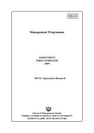
In this section, the operational flow of functions needed <strong>to</strong> process an item through a<br />
manufacturing facility has been briefly discussed. These operation flows within the<br />
CAD/CAM environment have been shown by a flow chart (Figure 1.3). The box number<br />
in figure refers the sequence number.<br />
1, 2. All planning must be the function of known cus<strong>to</strong>mer orders and sales<br />
forecasts. If expected demand are not known/or estimated, the enterprise<br />
will be working in a vacuum.<br />
3. Management decisions depend on expected orders leading <strong>to</strong> long-term<br />
order requirement that must be satisfied by either production or by<br />
subcontracting <strong>to</strong> outside sources (vendors).<br />
4. A relatively low term evaluation of facility requirement is needed <strong>to</strong> plan<br />
which parts can be manufactured. For example, enough machines of known<br />
capacity available, will material be available, can we perform our needs<br />
with the current workforce, and so on. The aggregate planning function<br />
determines what product quantities should be produced in what time periods<br />
<strong>to</strong> satisfy the long-term requirements. The result of this activity is called the<br />
master production schedule or master schedule. It is a schedule for final<br />
product, not for the components that go in<strong>to</strong> the final product.<br />
5. The master schedule is affected by current status conditions, so feedback<br />
loops come from many sourcesincluding problems that might occur with<br />
deliveries from vendors, trouble in the shop floor, analysis that reveals<br />
demands cannot be satisfied due <strong>to</strong> capacity problems, lack of vendors, and<br />
so on.<br />
6. The material requirements planning (MRP) function takes in<strong>to</strong><br />
consideration the current inven<strong>to</strong>ry levels for all components needed <strong>to</strong><br />
make the final products (a plant might have 20,000 part numbers and<br />
perhaps 100 final products for which master schedules have been<br />
determined) as well as the components‟ bills-of-materials and lead time<br />
information (obtained from design and process planning data) and evolves<br />
component master schedules for all components according <strong>to</strong> the demand<br />
requirements agreed upon. MRP does not take in<strong>to</strong> account whether<br />
manufacturing has sufficient capacity <strong>to</strong> handle the job releases, therefore<br />
capacity planning (6a) evaluates shop loading in terms of the requirements<br />
and feedback <strong>to</strong> the master schedule for corrective actions if any problems<br />
occur. A further function of MRP based on such analysis is determining<br />
whether components should be produced in-house (6b) or subcontracted <strong>to</strong><br />
outside vendors (6c).<br />
7. Computer aided design is the function that must be completed after a<br />
demand for a product has been determined. Thus, the sequence in which it<br />
is discussed in this section is not the same as that of sequence or cycle<br />
starting from cus<strong>to</strong>mer <strong>to</strong> inception through design, manufacturing,<br />
assembly and testing, and back <strong>to</strong> the cus<strong>to</strong>mer. The design engineer cannot<br />
talk in the same terms as the manufacturing engineer. For example, lines,<br />
splines, circles, and arcs come under geometrical design whereas pockets<br />
chamfers, holes and so on come under manufacturing design. Process<br />
planning function is <strong>to</strong> accomplish the language transition from design <strong>to</strong><br />
manufacturing.<br />
16
(1) (2)<br />
Known Cus<strong>to</strong>mer<br />
Order<br />
Sales<br />
Forecasts<br />
(3)<br />
Management Considerations<br />
<strong>Introduction</strong> <strong>to</strong> <strong>CIM</strong><br />
Inven<strong>to</strong>ry<br />
Control<br />
(4)<br />
Aggregate Planning<br />
(5)<br />
Master Production Schedule<br />
(7)<br />
Computer Aided Design/<br />
Computer Aided Engineering<br />
No<br />
(6a)<br />
Capacity<br />
Planning<br />
(6c)<br />
Vendor<br />
Orders<br />
On<br />
Schedule?<br />
Yes<br />
(6)<br />
Material Requirement Planning<br />
(MRP)<br />
(6b)<br />
Shop Floor<br />
Scheduling<br />
(9)<br />
Dispatching<br />
(11)<br />
Shop Floor Information and<br />
Control System (SFIS)<br />
(8)<br />
Computer Aided<br />
Process Planning<br />
(10) (10a)<br />
Production/Assembly and Test<br />
Quality Control<br />
Cus<strong>to</strong>mers<br />
Figure 1.3 : Flow of Operations in <strong>CIM</strong><br />
8. Some of the functions carried out by process planning modules are as :<br />
(a)<br />
(b)<br />
(c)<br />
(d)<br />
Sequence of operations required <strong>to</strong> manufacture a part<br />
Assessing the time requirement <strong>to</strong> complete the operations.<br />
Determining the type of machines and <strong>to</strong>oling required.<br />
Enumerate <strong>to</strong>lerance stacking problems that are credited due <strong>to</strong><br />
multiple cuts/multiple components related <strong>to</strong> a part type.<br />
The profitability and non-profitability of a part being manufactured can be<br />
ensured by the process planning function because it takes in<strong>to</strong> account the<br />
several ways in which a part being manufactured. In order <strong>to</strong> achieve a<br />
detailed schedule, the information related <strong>to</strong> process planning is fed in<strong>to</strong><br />
MRP analysis and also in the shop floor scheduling (6b). This step may<br />
result in the production of a detailed schedule for machines, <strong>to</strong>oling,<br />
fixtures, people and material handling devices, etc. To avoid the damage, all<br />
these have <strong>to</strong> come <strong>to</strong>gether at the right time.<br />
9. Dispatching is the function of releasing all required items needed <strong>to</strong><br />
perform an operation on a part so that part production must be<br />
completed within the schedule time.<br />
10. Production and assembly is accomplished through local control computers<br />
and /or programmable controllers.<br />
11. At last, shop floor information system is responsible for getting the required<br />
information passed <strong>to</strong> the downstream entities such as processing<br />
17
Fundamentals of <strong>CIM</strong><br />
SAQ 3<br />
(a)<br />
(b)<br />
equipment, local controllers and sequencing controllers, etc. In this way,<br />
real time status records are captured from the various equipments, machines<br />
and parts <strong>to</strong> activate feedback <strong>to</strong>ols so as <strong>to</strong> ensure the correction or normal<br />
continuation of operations in the desired manner.<br />
Describe briefly about MRP (Material Requirement Planning).<br />
What do you mean by Master Production Schedule or Master Schedule?<br />
1.5 CAM, CAD/CAM AND <strong>CIM</strong><br />
18<br />
CAD/CAM and <strong>CIM</strong> were introduced in brief in previous sections. In this section, CAM,<br />
CAD/CAM and <strong>CIM</strong> are discussed in detail.<br />
1.5.1 Computer Aided Manufacturing<br />
The effective use of computer technology in manufacturing planning and control is<br />
known as computer aided manufacturing (CAM). Manufacturing engineering functions<br />
such as process planning and numeric control (NC) are included in CAM. The<br />
application of CAM is divided in two categories:<br />
(i)<br />
(ii)<br />
manufacturing planning, and<br />
manufacturing control.<br />
Manufacturing Planning<br />
The applications of CAM in manufacturing planning are those in which computers<br />
are used directly <strong>to</strong> support the production function, but there is no direct<br />
connection between the computer and the process. The computer is used “offline”<br />
<strong>to</strong> provide information for the effective planning and management of the<br />
production activities. The following list surveys the application of CAM in this<br />
category:<br />
Computer Aided Process Planning (CAPP)<br />
The route sheets listing the operation sequences and workstations required<br />
for manufacturing the products and its components are prepared in process<br />
planning. These route sheets are prepared now a days using CAPP.<br />
Computer Assisted NC Part Programming<br />
Computer assisted part programming represents a method <strong>to</strong> generate the<br />
control instructions for the machine <strong>to</strong>ols for complex geometries rather<br />
than manual part programming. Part Programming for NC machines is step<br />
by step instructions according <strong>to</strong> which <strong>to</strong>ol movements on the part for<br />
metal removal is carried out.<br />
Computerized Machinability Data System<br />
Determination of speed and feed in metal cutting for the given machine<br />
<strong>to</strong>ols is a major problem. Computer program is written <strong>to</strong> propose the<br />
suitable condition <strong>to</strong> use for different materials. Estimation of <strong>to</strong>ol life<br />
needs information about material of <strong>to</strong>ols and workpiece, speed, feed and<br />
depth of cut etc. As per the cutting conditions, such calculations are <strong>to</strong> be
epeated. Therefore, application of computers for such purposes may assist<br />
process planner <strong>to</strong> a great extent.<br />
Development of Work Standard<br />
Responsibility for setting time standards on direct labour jobs performed in<br />
the fac<strong>to</strong>ry is taken by time study department. It is a very tedious and time<br />
consuming task <strong>to</strong> establish standards by direct time study. There are<br />
several computer packages also available in market for setting up the work<br />
standards. These computer programs use standard time data that have been<br />
developed for basic work element that comprise any manual task. By<br />
summing the times for the individual elements required <strong>to</strong> perform a new<br />
job, the program calculates the standard time for the job.<br />
Cost Estimating<br />
In many industries, cost estimation of a new product is being simplified by<br />
computerizing several key steps needed <strong>to</strong> prepare the estimate. Suitable<br />
labour and overhead rates are applied with the help of the computer<br />
programs <strong>to</strong> the sequence of planned operations involved in the components<br />
of new products. Individual components cost which range from the<br />
engineering bill of the materials <strong>to</strong> determine the overall product cost is<br />
summed up by the program.<br />
Production and Inven<strong>to</strong>ry Planning<br />
Extensive application in many of the functions in inven<strong>to</strong>ry planning and<br />
production control is being executed by the computer. The aforementioned<br />
functions are maintenance of inven<strong>to</strong>ry records, au<strong>to</strong>matic recording of<br />
s<strong>to</strong>ck items in the case when inven<strong>to</strong>ry is depleted, production scheduling,<br />
maintaining current priorities for the different production orders material<br />
requirements planning, and capacity planning etc.<br />
Computer Aided Line Balancing<br />
It is a very <strong>to</strong>ugh job <strong>to</strong> find the best allocation of work elements among<br />
stations on an assembly line if the line is of significant size. The problems<br />
are solved with the help of computer program.<br />
Manufacturing Control<br />
Another category of CAM application is development of computer supported<br />
system for implementing the manufacturing control functions. These control<br />
functions manage and control the physical operation in the fac<strong>to</strong>ry. These<br />
functions are as follows:<br />
• Process Moni<strong>to</strong>ring and Control<br />
Process moni<strong>to</strong>ring and control concerned with observing and regulating the<br />
production equipment of manufacturing processes in the plant. The<br />
applications of the process control are absorbed in au<strong>to</strong>mated production<br />
system. Which includes the example cases like transfer line assembly<br />
system, NC, robotics, material handling and flexible manufacturing systems.<br />
All these will be discussed later on. Process moni<strong>to</strong>ring and the control<br />
functions are deployed <strong>to</strong> regulate the actions of various production<br />
equipments. Some of the well known control systems used in the industry<br />
are as follows.<br />
Quality Control<br />
There are varieties of approaches that insure highest possible quality level<br />
in the manufacturing system and products and these are included in quality<br />
control.<br />
<strong>Introduction</strong> <strong>to</strong> <strong>CIM</strong><br />
19
Fundamentals of <strong>CIM</strong><br />
Shop Floor Control<br />
Production management techniques for collecting data from fac<strong>to</strong>ry<br />
operations and using these data <strong>to</strong> help control production and inven<strong>to</strong>ry in<br />
the fac<strong>to</strong>ry comes under shop floor control. Shop floor control and<br />
computerized fac<strong>to</strong>ry data collection systems are discussed in detail later<br />
on.<br />
Inven<strong>to</strong>ry Control<br />
The important thing about inven<strong>to</strong>ry control is that it maintains the most<br />
appropriate level of inven<strong>to</strong>ry in the face of two opposing objectives:<br />
minimizing the investment and s<strong>to</strong>rage cost of holding inven<strong>to</strong>ry and<br />
maximizing service <strong>to</strong> cus<strong>to</strong>mer.<br />
Just in Time Production System<br />
1.5.2 CAD/CAM<br />
A production system that is planned <strong>to</strong> deliver exactly the right number of<br />
each component <strong>to</strong> downstream workstations in the manufacturing sequence<br />
just at the time when that component is needed is known as just in time<br />
production system. This term is applicable <strong>to</strong> production operation and<br />
supplier delivery operation.<br />
All the engineering functions in design and manufacturing are included in CAD/CAM.<br />
During 1970s and early 1980s, CAD/CAM came in<strong>to</strong> the picture. Engineering activities<br />
in design include product design, engineering analysis and drafting whereas the process<br />
planning and NC part programming come in the manufacturing functions. The literal<br />
meaning of CAM is the manufacturing of the products with the aid of computers.<br />
Manufacturing is defined as a chain of interrelated activities that comprises designing,<br />
material selection, planning, production, quality assurance, management and marketing<br />
of discrete consumer and durable goods. CAM includes these aforementioned<br />
manufacturing functions.<br />
Scope of <strong>CIM</strong><br />
Scope of CAD/CAM<br />
Design<br />
Business<br />
Functions<br />
Fac<strong>to</strong>ry<br />
Operations<br />
Mfg.<br />
Planning<br />
Mfg.<br />
Control<br />
20<br />
Figure 1.4 : The Scope of CAD/CAM and <strong>CIM</strong>
CAD/CAM signifies an integration of design and manufacturing activities with the aid of<br />
computers. The conventional method of manufacturing a product which involves two<br />
separate procedures – designing the product and process planning – is a time consuming<br />
one and also involved duplication of effort by design and manufacturing personnel.<br />
These conventional methods are replaced by CAD/CAM. The direct link between<br />
product design and manufacturing is established with the help of CAD/CAM. While<br />
considering ideal CAD/CAM system, it takes the specific design of the product because<br />
it remains in the database and is converted in<strong>to</strong> a process plan for manufacturing a<br />
product. CAD/CAM system au<strong>to</strong>matically converts design of a product in<strong>to</strong> a process<br />
plan. On a numerically controlled machine <strong>to</strong>ol, a large portion of the processing can be<br />
completed. CAD/CAM au<strong>to</strong>matically generates NC part programming. Using<br />
telecommunication network, NC program is directly downloaded <strong>to</strong> the machine <strong>to</strong>ol in<br />
CAD/CAM system. Thus under CAD/CAM system, computer implements all the<br />
functions such as Product design, NC programming and Physical Production.<br />
Error!<br />
CAD<br />
Geometric Modeling<br />
Engineering Analysis<br />
Design Review and Evaluation<br />
Au<strong>to</strong>mation Drafting<br />
<strong>Introduction</strong> <strong>to</strong> <strong>CIM</strong><br />
Computerized<br />
Business System<br />
Order Entry<br />
Accounting Payroll<br />
Business<br />
Functions<br />
Design<br />
Fac<strong>to</strong>ry<br />
Operation<br />
Mfg. Control<br />
Mfg.<br />
Planning<br />
CAM<br />
Cost Estimation<br />
CAPP NC Part<br />
Programming<br />
Computerized Work<br />
stds<br />
MRP, Capacity<br />
Planning<br />
CAM<br />
Process Control<br />
Process Moni<strong>to</strong>ring<br />
Shop Floor Control<br />
Computer-aided Inspection<br />
Figure 1.5 : Computerized Element of <strong>CIM</strong> System<br />
1.5.3 Computer Integrated Manufacturing<br />
<strong>CIM</strong> sums up all of the manufacturing functions of CAD/CAM along with firm‟s<br />
business functions which are related <strong>to</strong> manufacturing. <strong>CIM</strong> system includes the<br />
application of computer and communication technologies <strong>to</strong> all of the operational<br />
functions and information processing functions starting from the order receipt through<br />
design and production <strong>to</strong> product delivery. Figure 1.4 depicts the scope of <strong>CIM</strong> and its<br />
comparison with the limited scope of CAD/CAM.<br />
The main aim of the <strong>CIM</strong> is <strong>to</strong> incorporate the firm‟s operations related <strong>to</strong> production in<br />
an integrated computer system <strong>to</strong> assist, augment, and au<strong>to</strong>mate the operations.<br />
Computer system <strong>to</strong>uches all the activities throughout the firm that support<br />
manufacturing. In <strong>CIM</strong>, the output of one‟s activities act as input <strong>to</strong> the other activity and<br />
it starts with the sales order and finishes with its delivery. The components of the<br />
21
Fundamentals of <strong>CIM</strong><br />
integrated computer system are illustrated in Figure 1.5. Initially, cus<strong>to</strong>mer‟s orders that<br />
contain the specifications describing the product are entered by either the company‟s<br />
sales force or directly by the cus<strong>to</strong>mer in<strong>to</strong> a computerized order entry system. Product<br />
design department takes these specifications as the input. Manufacturing engineering<br />
takes its input from the output of the design department where process planning, <strong>to</strong>ol<br />
design, and similar activities are supported by the <strong>CIM</strong> system. CAPP performs process<br />
planning. On a CAD system, using the product model which is generated during product<br />
design, <strong>to</strong>ol and fixture design is done. Manufacturing engineering provides its output<br />
in<strong>to</strong> production planning and control, where material requirements planning and<br />
scheduling are performed using the computer system.<br />
SAQ 4<br />
(a)<br />
(b)<br />
What do you mean by CAM, CAD/CAM and <strong>CIM</strong>? Differentiate them.<br />
What are the different types of CAM application? Discuss each type in<br />
detail.<br />
1.6 INTEGRATION APPROACHES OF CAD/CAM<br />
PRELIMINARY STATUS<br />
Majority of the manufacturer prefer <strong>to</strong> specify the rough design of their component. This<br />
information is sent <strong>to</strong> the potential supplier for further studies. Then, supplier evaluates<br />
the <strong>to</strong>oling, fixturing and other requirements of the given drawing and asses its<br />
manufacturing suitability keeping in view its production and other technological<br />
features. The completed designs having such details are sent again <strong>to</strong> the manufacturer<br />
by the supplier. Adopting the simulation and other optimization <strong>to</strong>ol, manufacturer<br />
transfers the drawing <strong>to</strong> the dedicated CAD system. One more cycle of drawing are<br />
reverted back <strong>to</strong> the supplier, where moderation incorporated by the manufacturer is<br />
included. At this stage, supplier also includes some of the changes according <strong>to</strong> the<br />
suggestion furnished by the manufacturer. Detail control cycle of the design transferred<br />
<strong>to</strong> illustrate the mechanism of CAD system is described in Figure 1.6.<br />
Rough/Preliminary Draft<br />
Receipt<br />
Detailed Draft<br />
Receipt<br />
Design Checking<br />
Receipt<br />
Control Cycle<br />
Manufacturer<br />
Final Design<br />
Production Clearance<br />
Supplier<br />
22<br />
Figure 1.6 : Unconnected CAD Systems<br />
Transfer of Drawing
Format Showing Data Exchange<br />
Software incompatibility is the major hurdle that restricts the easy data sharing<br />
between two or more system. It happens due <strong>to</strong> the fact that supplier of the<br />
computer application may develop the design configuration for different priory<br />
format <strong>to</strong> s<strong>to</strong>re the data required and its display. In order <strong>to</strong> ensure the<br />
compatibility for smooth data sharing, there is a need of neutral data exchange<br />
format. Here the term neutral refers <strong>to</strong> a format that can be easily exploited by<br />
various systems. Reasonably good data exchange format or standard or neutral file<br />
should satisfy a minimum set of requirement. These requirements are concerned<br />
with the common entities needed in different modeling system such as wire frame<br />
entity and surface entity etc. It is expected from a standard format that it should<br />
become compact and help in achieving faster data s<strong>to</strong>rage and retrieval. Some of<br />
the popular standards reported in the various books are IGES (Initial Graphics<br />
Exchange Specification), and PDES (Product Data Exchange Standards).<br />
In the 1980s, the features of IGES were published and in subsequent years the<br />
same has been thoroughly updated. Among the dissimilar CAD/CAM system, the<br />
first well known data exchange format was reported by IGES only. The same<br />
format has also been adopted <strong>to</strong> communicate the data among the manufacturer<br />
and the suppliers. Therefore, it can be inferred that IGES helps <strong>to</strong> develop a<br />
communication interface among the different system.<br />
<strong>Introduction</strong> <strong>to</strong> <strong>CIM</strong><br />
Rough/Preliminary Draft<br />
Detailed Draft<br />
Design Checking<br />
Control Cycle<br />
Final Design<br />
Production Clearance<br />
Manufacturer<br />
Supplier<br />
Figure 1.7 : CAD Systems with Electronic Data Transfer<br />
Transfer of Drawing<br />
Under the aegis of International Organization for Standardization (ISO), massive<br />
efforts have been pursued <strong>to</strong> develop an international standard known as STEP<br />
(Standard for Transfer and Exchange of Product Model Data). It refers <strong>to</strong> global<br />
standardization of exchange of information pertaining <strong>to</strong> the computer application<br />
in manufacturing. Features of STEP have been utilized <strong>to</strong> evolve another data<br />
exchange standard known as product data exchange,which has found wide ranging<br />
application for different type of work in the industry. The major difference<br />
between IGES and PDES is that IGES utilizes entities (different type of geometric<br />
entities, structure entities etc.) as basic element, whereas PDES data exchange is<br />
carried out in terms of application.<br />
23
Fundamentals of <strong>CIM</strong> Operating mechanism of PDES is described by three layers. These are :<br />
(1) application layer,<br />
(2) logical layer, and<br />
(3) physical layer.<br />
The user and PDES are interfaced by the application layer, where application<br />
model is clearly defined and different types of information is expressed using<br />
information modeling techniques. The main task of logical layer is <strong>to</strong> support<br />
faultless, consistent and computer independent description so that sufficient<br />
information is available <strong>to</strong> encapsulate the wide range of applications. In order <strong>to</strong><br />
maintain the structure and format of exchange file, the role of physical layer<br />
comes in<strong>to</strong> picture <strong>to</strong> efficiently manage the magnitude of the file sizes.<br />
Rough/Preliminary Draft<br />
Detailed Draft<br />
Design Checking<br />
Final Design<br />
Control Cycle<br />
Production Clearance<br />
Manufacturer<br />
Supplier<br />
Transfer of Drawing<br />
SAQ 5<br />
Figure 1.8 : CAD Systems with Context <strong>to</strong> Inter-Application Communication<br />
Another format for data exchange has gained ground in recent years <strong>to</strong> assist in the<br />
interchange of drawings between Au<strong>to</strong>CAD and other program. It is known as<br />
DXF, which stands for Drawing Exchange File Format. This format is capable of<br />
implementing features of Au<strong>to</strong>CAD and also converts them in<strong>to</strong> file<br />
representation. Majority of the software packages supports the DXF format and<br />
the ASCII test files also includes DXF files.<br />
Irrespective of data exchange systems, the common way through which drawing<br />
details are transferred electronically among the different CAD system are<br />
explained in Figures 1.7 and 1.8.<br />
(a)<br />
(b)<br />
Describe the role of IGES and PDES as a data exchange format between<br />
CAD/CAM. Enlist the reason for preferring PDES over IGES.<br />
Describe the steps through which electronic data transfer takes place from<br />
manufacturer <strong>to</strong> supplier.<br />
24
1.7 SUMMARY<br />
<strong>Introduction</strong> <strong>to</strong> <strong>CIM</strong><br />
This unit highlights various components of <strong>CIM</strong> and also explains the interface among<br />
them. Scope and integration of CAD/CAM and <strong>CIM</strong> have been clearly remarketed.<br />
Adequate attention has been focused in this unit about various component related <strong>to</strong><br />
<strong>CIM</strong>. Where it is explained that <strong>CIM</strong> is a process of using computers and<br />
communications network <strong>to</strong> transform island of enabling technologies in<strong>to</strong> a highly<br />
interconnected manufacturing system. Details pertaining <strong>to</strong> enterprise wide integrating<br />
and <strong>CIM</strong> wheel are included in this unit <strong>to</strong> provide glimpses about the wider capacity of<br />
underlined subject. CAD/CAM integration approaches include initial position, data<br />
exchange, application integration, and their general effects. After going through the<br />
content of this unit, one can easily comprehend the importance of <strong>CIM</strong> in enhancing the<br />
productivity for different types of production system.<br />
1.8 KEY WORDS<br />
Computer Integrated<br />
Manufacturing<br />
: <strong>CIM</strong> is a process of using computers and communication<br />
networks <strong>to</strong> transform islands of enabling technologies<br />
in<strong>to</strong> a highly interconnected manufacturing system.<br />
Computer Aided Design : Computer aided design denotes the use of the computer<br />
systems <strong>to</strong> support the product design system.<br />
Computer Aided<br />
Manufacturing<br />
: The term denotes the pervasive use of computer system<br />
<strong>to</strong> design the product, <strong>to</strong> plan the production, control the<br />
operation and perform the business related functions<br />
needed in the manufacturing firm.<br />
CAD/CAM : Some computer system performs both the CAD and<br />
CAM, and so the term CAD/CAM is used <strong>to</strong> indicate the<br />
integration of the two in<strong>to</strong> one system.<br />
<strong>CIM</strong> Wheel : The society of manufacturing engineers (SME) <strong>CIM</strong><br />
wheel provides a clear portrayal of relationships among<br />
all parts of an enterprise.<br />
Process Planning : Process planning evolves the sequence of operations<br />
required for manufacturing a part, the times required <strong>to</strong><br />
accomplish the operations, the machines and <strong>to</strong>oling<br />
required, and evaluates <strong>to</strong>lerance stacking problems that<br />
accrue from multiple cuts and/or multiple components<br />
that comprise a part.<br />
25
Fundamentals of <strong>CIM</strong><br />
26
COMPUTER INTEGRATED<br />
MANUFACTURING<br />
<strong>Introduction</strong> <strong>to</strong> <strong>CIM</strong><br />
Computer Integrated Manufacturing (<strong>CIM</strong>) is the au<strong>to</strong>mated version of the<br />
manufacturing process, where the three major manufacturing functions, product and<br />
process design, planning and control, and the manufacturing process itself are replaced<br />
by the computer au<strong>to</strong>mated technologies. All these technologies are tied <strong>to</strong>gether using a<br />
network and integrated database. Thus in a fully integrated system, the areas of design,<br />
testing, fabrication, assembly, inspection and material handling are not only au<strong>to</strong>mated<br />
but also integrated with each other and with the manufacturing planning and scheduling<br />
function.<br />
In Block 1, various aspects of <strong>CIM</strong> fundamentals are covered. The integration approach<br />
of CAD/CAM have been discussed. It also covers au<strong>to</strong>mated materials handling systems,<br />
AGVS, AS/RS and design aspects of AS/RS.<br />
Block 2 covers the role of CNC machines in <strong>CIM</strong> environment, recent trends and<br />
advances, <strong>to</strong>ol handling system. It also discusses more about the FMS, CMS and group<br />
technology applications in <strong>CIM</strong>.<br />
Block 3 includes <strong>CIM</strong> modeling and operations, computer simulations of FMS and<br />
benefits of <strong>CIM</strong>. Computer aided process planning will be discussed in detail with<br />
examples for simple shapes and also covers advances in CAPP. This block also covers<br />
various planning systems like MRP, MRP-II, ERP and their integrations with <strong>CIM</strong>.<br />
Block 4 covers various simulation languages, illustrative examples and case studies in<br />
<strong>CIM</strong>. Various communication and control systems have been discussed. Some important<br />
network <strong>to</strong>ols like LAN standards, pro<strong>to</strong>cols, manufacturing sensors, Bar Codes, and<br />
manufacturing data base management systems have been discussed. Lastly it covers<br />
future trends in manufacturing, future au<strong>to</strong>mated fac<strong>to</strong>ry and social impact of au<strong>to</strong>mation<br />
of fac<strong>to</strong>ries.<br />
27
Fundamentals of <strong>CIM</strong><br />
FUNDAMENTALS OF <strong>CIM</strong><br />
Technology has played the dominant role in the productivity growth of most nations and<br />
has provided the competitive edge <strong>to</strong> firms that have adopted in early and implemented it<br />
successfully. While each of the manufacturing and information technologies is a<br />
powerful <strong>to</strong>ol by itself and can be adopted separately, their benefits grow exponentially<br />
when they are integrated with each other. This is particularly the case with <strong>CIM</strong><br />
technologies.<br />
In this block, we shall discuss the basics and fundamentals of Computer Integrated<br />
Manufacturing.<br />
Unit 1 discusses more about the introduction part of the <strong>CIM</strong>. Further it explains the<br />
interrelationship between CAD, CAM and <strong>CIM</strong>, and benefits of <strong>CIM</strong>. The <strong>CIM</strong> wheel<br />
provides a clear portrayal of relationship among all parts of an enterprise.<br />
Unit 2 elaborates the various types of inspection systems, inspection procedures,<br />
inspection vs testing, Coordinate Measuring Machine (CMM). The CMM is an<br />
electromechanical system designed <strong>to</strong> perform coordinate metrology.<br />
Unit 3 explains the types of AGVS and their control systems. In this unit, we have dealt<br />
with the au<strong>to</strong>mated guided vehicles and robots used in the industry.<br />
In Unit 4, we discuss the various types of AS/RS and various fac<strong>to</strong>rs of design of an<br />
AS/RS. Here we also dealt with the AS/RS used in industries <strong>to</strong> handle, s<strong>to</strong>re and<br />
retrieve materials with precision, accuracy and speed under defined degree of<br />
au<strong>to</strong>mation.<br />
28