E - IFToMM
E - IFToMM
E - IFToMM

Create successful ePaper yourself
Turn your PDF publications into a flip-book with our unique Google optimized e-Paper software.
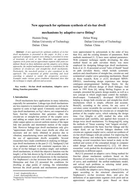
New approach for optimum synthesis of six-bar dwell<br />
mechanisms by adaptive curve fitting*<br />
Huimin Dong<br />
Delun Wang<br />
Dalian University of Technology<br />
Dalian University of Technology<br />
Dalian China<br />
Dalian China<br />
∗ Abstract—A new approach for optimum synthesis of six-bar<br />
dwell mechanisms is presented in this paper. At first, a new<br />
approach of adaptive segment curve fitting is presented in terms<br />
of invariants of circle or line. Meanwhile, an approximate<br />
segment circle point and an approximate segment slide point are<br />
defined. Based on these definitions and the adaptive curve fitting<br />
approache, the unified mathematical model is established for the<br />
synthesis of circular-arc and straight-line dwell mechanisms.<br />
Particularly, the non-dwell portion is also considered in the<br />
approach. The co-operation of global searching and local<br />
searching is adopted to satisfy the prospective accuracy.<br />
Examples under various given conditions illustrated show that<br />
the technique is simple, efficient and accurate.<br />
Key words:Six-bar dwell mechanism, Adaptive curve<br />
fitting, Function generation<br />
I. Introduction<br />
Dwell mechanisms have applications in many industries,<br />
especially for automation. Linkage-type dwell mechanisms<br />
are less expensive to manufacture and maintain, and can be<br />
superior to cams at high speed. Commonly used linkagetype<br />
dwell mechanisms, as Fig.1 shows, are composed of a<br />
basic four-bar mechanism that generates either the<br />
circular-arc or straight-line portion of the coupler curve<br />
and adding an output dyad with rocker output option or<br />
slider output option to convert uniform motion of the input<br />
link into periodic and intermittent motion of the output<br />
link. However linkage-type dwell mechanisms only give<br />
"approximate dwells". Since exact dwells are often not<br />
necessary and are rarely obtained in practice due to<br />
vibration, manufacturing errors and backlash, this makes<br />
the use of approximate dwells acceptable. Several<br />
researchers have made contribution to studying on linkagetype<br />
dwell mechanisms in the past [1-12]. Sandgren[1] led<br />
to an optimum method with constraint equations into a<br />
class of six-bar linkages to produce single- and multipledwell<br />
mechanisms, in which the objective function was the<br />
length l 5 of the link shown in fig.1b with invariable and the<br />
optimal parameters were all dimensions in the mechanism.<br />
For Stephenson’s six-bar inversion three with pin jointed,<br />
Shimojima and Jizai [2] presented the conditions for<br />
dwelling at edge points of rocking, the relationships<br />
between the dwell periods and mechanisms parameters<br />
∗ E-mail : donghm@dlut.edu.cn<br />
E-mail : dlunwang@dlut.edu.cn<br />
*Supported by National Natural Science Foundation of China under grant<br />
No. 50475154<br />
were approximated by polynomials in the order of less<br />
than five, and the existing domains of parameters. Both<br />
methods mentioned [1, 2] have more optimal parameters.<br />
With computer technique rapidly developing, the atlas<br />
method based on path curvature theory was more<br />
employed for designing linkage-type dwell mechanisms.<br />
Kota et al. [3, 4] presented several "rules of thumb" based<br />
on path curvature theory, which includs systematic<br />
analysis and classification of straight-line, circular-arc and<br />
symmetrical coupler curve generating mechanisms. Based<br />
on those research, Kota et al.[5] developed MINN-<br />
DWELL, transforming design experience into design<br />
catalogues--preprogrammed building blocks for the<br />
intelligent and efficient design of dwell linkages. And<br />
more in 1991 Kota [6], taking Stirling Engines as an<br />
example, presented the generic design models, as well as a<br />
new concept in which single-input control the multipledwell-output.<br />
Venkatesh[7] developed RECDWELL<br />
helping to design both circular-arc and straight-line dwell<br />
mechanisms which is simple, efficient and accurate.<br />
Beier[8], according to the axiom, for any curve if<br />
curvature center invariable the curvature radii is constant,<br />
presented a method looking for circular-arc or straight-line<br />
portion of the coupler curve, which reducing the design<br />
time. Cao Qinglin et al[9] studied the atlas with<br />
symmetrical path carefully, and applied their research to<br />
design twice dwell mechanisms. Yu Hongying[10], using<br />
the methods of “linear scanning “and “tangent envelop”,<br />
separately synthesized the basic four-bar linkage and the<br />
output dyad, set up four-bar linkages database with<br />
circular-arc segment coupler curve, carried out synthesis of<br />
six-bar dwell linkages with pin jointed. For improving the<br />
design efficiency and reducing the randomicity of initial<br />
selecting, several researchers have turned to study on the<br />
method and system of the conceptual design in computer<br />
aided design dwell mechanisms[11], [12]. All above<br />
researches’ work pushed the development of six-bar dwell<br />
mechanisms in different aspect.<br />
Ref.[13] presented an adaptive curve fitting method for<br />
four-bar planar mechanism synthesis based on the<br />
theoretics of curvature, by means of searching a invariants<br />
of curve, and established the unified mathematic model,<br />
and solved such problems as selecting initial point,<br />
capturing global optimal solution.<br />
We modify the adaptive curve fitting method [13] in this<br />
paper according to the structural characteristic of<br />
Stephenson’s six-bar inversion three, and give the<br />
definitions of an approximate segment circle point and an<br />
approximate segment slide point. Based on these
definitions and the approach, establish the unified<br />
mathematical model for the synthesis of circular-arc and<br />
straight-line dwell mechanisms. Particularly, consider the<br />
non-dwell portion in the approach. Adopt the co-operation<br />
of global searching and local searching to satisfy the<br />
prospective accuracy. Examples under various given<br />
conditions illustrate that the technique is simple, efficient<br />
and accurate.<br />
E<br />
E<br />
E<br />
A<br />
E<br />
A<br />
B<br />
A<br />
B<br />
B<br />
E<br />
F<br />
C<br />
F<br />
E<br />
C<br />
C<br />
G<br />
D<br />
G<br />
D<br />
D<br />
Fig 1 Constructions of Stephenson Ш six-bar dwell linkages<br />
E<br />
(c)<br />
II. Representation of coupler curve<br />
As shown in Fig.1, the dwell motion condition of sixbar<br />
linkages is either the straight-line or circular-arc<br />
portion of the path traced by the coupler point E in a basic<br />
four-bar linkage. According to the geometry characteristic<br />
of four-bar linkages, in coordinate system (o f , x f , y f ) shown<br />
in Fig.2, the point E( l e , β ) can be easily expressed as<br />
⎧x<br />
E<br />
= l1<br />
cosϕ<br />
+ le<br />
⋅ cos( γ + β )<br />
⎨<br />
(1)<br />
⎩ y<br />
E<br />
= l1<br />
sinϕ<br />
+ le<br />
⋅ sin( γ + β )<br />
Obviously, the trace of point E ( x E<br />
, y E<br />
) is nonlinear<br />
functions aboutϕ . That is, any point on the coupler plane<br />
(a)<br />
l e<br />
(b)<br />
A<br />
E<br />
l 5<br />
F<br />
E<br />
l 5<br />
B<br />
l1<br />
l e<br />
G<br />
A<br />
B<br />
l 1<br />
l e<br />
A<br />
l6<br />
F<br />
B<br />
l 1<br />
l 2<br />
l4<br />
l 2<br />
G<br />
l 4<br />
C<br />
l 3<br />
C<br />
D<br />
l 3<br />
C<br />
l 2<br />
l 3<br />
l 4<br />
D<br />
D<br />
of basic four-bar linkages can be expressed as nonlinear<br />
functions about input angleϕ , whose properties depend on<br />
the position on the coupler plane.<br />
y f<br />
o f (A)<br />
B<br />
l e<br />
φ<br />
x f<br />
E<br />
β<br />
C<br />
γ<br />
Fig.2 Coupler curve of planar four-bar linkage<br />
III. The approach of adaptive segment curve fitting<br />
The first step of synthesis of dwell mechanisms with the<br />
type of Stephenson’s III six-bar is for searching coupler<br />
point E in a basic four-bar linkage, which generates<br />
approximate straight-line or circler-arc portion. Based on<br />
the approach of adaptive curve fitting to search<br />
approximate characteristic point presented in Ref.[13], this<br />
paper presents an adaptive segment curve fitting method to<br />
find approximate local characteristic point.<br />
A. Adaptive segment circle fitting<br />
As shown in Fig.3, there is the set of discrete points E i<br />
of any coupler point in the basic four-bar linkage, a circle<br />
is chosen to fit the segment curve E k1 Ek<br />
2 . Based on the<br />
adaptive fitting circle[13], the optimal mathematical model<br />
of a local adaptive fitting circle can be written as<br />
min max f z<br />
f<br />
where f k<br />
( z)<br />
k<br />
z<br />
k1<br />
≤k≤k2<br />
i<br />
( )<br />
D<br />
2<br />
2<br />
( z) = ( x − x ) + ( y − y ) )<br />
Ek<br />
T<br />
[ x , y , r] , z ∈ R<br />
0 0<br />
Z<br />
0<br />
Ek<br />
− r<br />
z =<br />
is the fitting error between a discrete point E i<br />
and the adaptive fitting circle, and<br />
0<br />
1<br />
2<br />
(2)<br />
T<br />
z = [ x , y , r ] are the<br />
optimal parameters, in witch ( x0 , y<br />
0<br />
) is the coordinates of<br />
the circle center and r is the radius of the fitting circle.<br />
It is necessary to indicate that, the length of segment<br />
curve fitted lies on the intermission angle ∆ ϕ m , the<br />
position depends on the k 1 and k 2 , select a different segment<br />
get a different fitting circle and different fitting error. Here,<br />
we give the definition of the local adaptive fitting circle.<br />
Definition A.1 Based on the properties of the set of<br />
discrete points E i in the given path and the given<br />
intermission angle ∆ ϕ , a circle is adaptively located by<br />
m<br />
the circle fitting in the principle of minimum maximum<br />
fitting error in all segments, witch is called a local adaptive<br />
fitting circle.<br />
0<br />
0
A local adaptive fitting circle have the same properties<br />
with an adaptive fitting circle in Ref [13]. For a basic fourbar<br />
linkage, every tracing point of a moving body is<br />
corresponding to a local adaptive fitting circle, whose<br />
difference of those is only the maximum error. Therefore,<br />
we can define the approximate segment circle point.<br />
Definition A.2 For a basic four-bar linkage, a tracing<br />
point of a moving body is corresponding to a local<br />
adaptive fitting circle, whose maximum fitting error in<br />
normal direction reaches the minimum with respect to<br />
other tracing points in its neighborhood, within the range<br />
of the intermission angle ∆ ϕ m , called approximate<br />
adaptive segment circle point, or an approximate segment<br />
circle point for short.<br />
An approximate segment circle point has three<br />
meanings about minimum maximum: one is the adaptive<br />
segment fitting circle, which leads to the maximum fitting<br />
error with a circle get minimum, the second one is to<br />
search for a best segment in the given path, and the third<br />
one is to search for a best approximate segment circle<br />
point on the moving body, which traces a segment of a<br />
curve closest to a circle-arc, or the maximum fitting error<br />
gets minimum in its neighborhood.<br />
The minimum maximum fitting error of adaptive<br />
segment fitting circle is a nonlinear function of the<br />
coordinates of the tracing point on the moving body.<br />
Therefore, there must exist extreme values of the<br />
minimum maximum fitting error for all adaptive fitting<br />
circles with respect to their tracing points of moving body.<br />
Theorem A.1 There must exist several approximate<br />
segment circle points on the moving body in<br />
nondegenerated planar motion.<br />
E k1<br />
E k<br />
r<br />
(x<br />
y 0 ,y 0 )<br />
F<br />
x F<br />
o f<br />
E k2<br />
f k (z)<br />
Fig.3 Local adaptive fitting circle of coupler curve<br />
As shown in Fig.1a and 1b six-bar dwell mechanisms,<br />
the point E is an approximate segment circle point on the<br />
coupler plane of a basic four-bar linkage. The center<br />
coordinate x , ) and radius r of that are the coordinate<br />
( 0 y0<br />
of the point F ( y )<br />
of the link EF.<br />
x in dwell period and the length l 5<br />
F<br />
,<br />
0 F 0<br />
B. Adaptive segment straight-line fitting<br />
As shown in Fig.4, there is the set of discrete points E i<br />
of any coupler point in the given intermission angle ∆ϕ<br />
m of<br />
a basic four-bar linkage. Fitting the segment<br />
curve Ek1 Ek<br />
2 needs to employ an adaptive fitting line,<br />
which is similar to an adaptive segment fitting circle.<br />
Hence, we can also give the definition of a local adaptive<br />
fitting line.<br />
y f<br />
o f<br />
E k1<br />
x f<br />
E k<br />
f k (z)<br />
E k2<br />
Fig.4 Local adaptive fitting line of coupler curve<br />
Definition B.1 Based on the properties of the set of<br />
discrete points E in the given path and the given<br />
i<br />
intermission angle ∆ ϕ m , a straight-line is adaptively<br />
located by the line fitting in the principle of minimum<br />
maximum fitting error in all segments, which is called a<br />
local adaptive fitting line.<br />
The optimal mathematical model of an adaptive line can<br />
be written as<br />
min max f z<br />
where ( z)<br />
f<br />
z<br />
j<br />
j1<br />
≤ j≤<br />
j2<br />
j<br />
( )<br />
2<br />
( z) = y<br />
( )<br />
E<br />
− kxE<br />
− b / 1+<br />
k<br />
j<br />
j<br />
T<br />
[ k,<br />
b] ,z∈<br />
RZ<br />
1<br />
2<br />
(3)<br />
z =<br />
f j<br />
is the fitting error between a discrete point of<br />
the given path, the adaptive fitting line: k and b are the<br />
optimal parameters.<br />
The properties of adaptive segment fitting line are<br />
similar to those of adaptive segment fitting circle. In the<br />
same way, we can give the definition of an approximate<br />
adaptive segment slide point.<br />
Definition B.2 For a basic four-bar linkage, a tracing<br />
point of a moving body is corresponding to the adaptive<br />
segment fitting line, whose maximum fitting error in<br />
normal direction reaches the minimum with respect to<br />
other tracing points in its neighborhood, within the range<br />
of the intermission angle ∆ ϕ m , called approximate<br />
adaptive segment slide point, or an approximate segment<br />
slide point for short.<br />
The minimum maximum fitting error of adaptive<br />
segment fitting line is also a nonlinear function, which<br />
solving process is same with that of the approximate<br />
segment circle point and solutions must be existent.
Theorem B.1 There must exist several approximate<br />
segment slide points on the moving body in<br />
nondegenerated planar motion.<br />
The point E in Fig.1c is an approximate segment slide<br />
point on the coupler plane of a basic four-bar linkage,<br />
which is corresponding to dwell position of the output link.<br />
C. the synthesis of output dyads<br />
After finding the segment characteristic point E on the<br />
coupler plane of a basic four-bar linkage in the dwell<br />
period angle ∆ ϕ , the next step is the synthesis of output<br />
m<br />
dyads to satisfy non-dwell function requirement, such as<br />
having RRR, RPR as well as RRP dyadic configuration.<br />
C. 1 Rocker output option<br />
Fig.1a and 1c show the most commonly used six-bar<br />
type dwell mechanism with rocker output. Based on<br />
getting the approximate segment characteristic point E,<br />
circle point or slide point, on the coupler plane of a basic<br />
four-bar linkage, the synthesis of the output dyad RRR and<br />
RPR is to search the fixed pivot.<br />
According to the given transmission function in the nondwell<br />
section, under the precondition of all parameters in<br />
the basic four-bar linkage known, the object function of<br />
the optimal mathematical model can be expressed as<br />
Ⅱ<br />
Ⅱ<br />
f z = max ψ −ψ<br />
(4)<br />
Ⅱ<br />
ψ<br />
j<br />
Ⅱ<br />
j<br />
j<br />
( )<br />
Ⅱ<br />
j<br />
where is the output angle (output function of the<br />
rocker), ψ is the desired output function of the rocker,<br />
the optimal parameters are ( ) T<br />
coordinate ( x<br />
G<br />
, y G<br />
) of fixed pivot.<br />
j<br />
z = x , y G G<br />
which are the<br />
For the dyad RRR shown in Fig.1a, the output angleψ ,<br />
according to the principle of the distance between the two<br />
pivots of the link keeping constant, can be found as follow<br />
equations<br />
2<br />
( x − x ) + ( y − y ) 2<br />
l6 =<br />
G F0 G F 0<br />
(5)<br />
and<br />
2<br />
2 2<br />
( ⎪⎧<br />
x − x ) + ( y − y ) = l<br />
E<br />
E 5<br />
⎨<br />
2<br />
2 2<br />
( ⎪⎩ x − xG) + ( y − yG)<br />
= l6<br />
(6)<br />
substituting equation (5) into equations (6) and rearranging<br />
them yields<br />
⎧xF<br />
= xE<br />
+ pa1<br />
− qa2<br />
⎨<br />
⎩y<br />
F<br />
= xF<br />
+ pa2<br />
− qa1<br />
(7)<br />
Where<br />
a = x − x , a = y − y a<br />
2<br />
= a<br />
2<br />
a (8)<br />
1 G E 2 G E<br />
,<br />
3 1<br />
+<br />
2<br />
Ⅱ<br />
j<br />
2 2<br />
⎧ ( a + −<br />
⎪ =<br />
3<br />
l5<br />
l6<br />
)<br />
p<br />
2a3<br />
⎨<br />
(9)<br />
2<br />
⎪ l<br />
2<br />
q = M ⋅<br />
5<br />
− p<br />
⎪⎩<br />
a3<br />
Equation (9) has two solutions, obtained from<br />
the ± condition of the coefficient M, which depends on the<br />
initial position of ( x<br />
F<br />
y ). If y<br />
F<br />
>= yG<br />
, then<br />
0<br />
,<br />
F 0<br />
Ⅱ<br />
x<br />
F<br />
− xG<br />
ψ<br />
j<br />
= arccos(<br />
) (10a)<br />
2<br />
2<br />
( x<br />
F<br />
− xG<br />
) + ( y<br />
F<br />
− yG<br />
)<br />
otherwise<br />
x<br />
F<br />
− xG<br />
ψ Ⅱ j<br />
= 2π<br />
− arccos(<br />
) (10b)<br />
2<br />
2<br />
( x<br />
F<br />
− xG<br />
) + ( y<br />
F<br />
− yG<br />
)<br />
For the dyad RPR shown in Fig.1c, the point E is the<br />
segment slide point on the coupler plane of the basic fourbar<br />
linkage, whose line segment is corresponding to the<br />
rocker position with dwell. According to the geometry<br />
Ⅱ<br />
properties of the output dyad RPR, the output angle ψ<br />
j<br />
,<br />
can be found as follow equation<br />
y = kx b<br />
(11)<br />
where ( )<br />
F<br />
y F<br />
F F<br />
+<br />
x , are the coordinates of fixed pivot F; k and<br />
b are the parameters of point E at the position of the<br />
adaptive segment fitting line. If y<br />
E<br />
>= kxF<br />
+ b , then<br />
Ⅱ<br />
x<br />
E<br />
− x<br />
F<br />
ψ<br />
j<br />
= arccos(<br />
) (12a)<br />
2<br />
2<br />
( x<br />
E<br />
− x<br />
F<br />
) + ( x<br />
E<br />
− kxF<br />
− b)<br />
otherwise<br />
x<br />
E<br />
− x<br />
F<br />
ψ Ⅱ<br />
j<br />
= 2π<br />
− arccos(<br />
) (12b)<br />
2<br />
2<br />
( x − x ) + ( x − kx − b)<br />
E<br />
C. 2 Slider output option<br />
The output link is a slider in the six-bar type dwell<br />
mechanism shown in Fig.1b which transforms the rotating<br />
input motion to the translating output and dwell. After<br />
selecting an approximate segment circle point on the<br />
coupler plane as pivot E, the synthesis of the output dyad<br />
with slider output is to search the tilted angle θ of the<br />
guideway according to the given transmission function in<br />
the non-dwell section. As with the section C. 1 the object<br />
function of the optimal mathematical model in the nondwell<br />
portion can be constructed as<br />
Ⅱ<br />
Ⅱ<br />
f θ = max s − s<br />
(13)<br />
j<br />
( )<br />
Ⅱ<br />
Ⅱ<br />
where s<br />
j<br />
is the output displacement of the slider F, s Ⅱ j<br />
is<br />
the desired output displacement, θ is the optimal<br />
parameter which is the tilted angle of the guideway with<br />
respect to the x f . axis. The output displacement of the slider<br />
F can be found as follow equations<br />
F<br />
j<br />
j<br />
E<br />
F
2<br />
2 2<br />
⎪⎧<br />
( xF<br />
− x<br />
E<br />
) + ( y<br />
F<br />
− y<br />
E<br />
) = l5<br />
⎨<br />
(14)<br />
⎪⎩<br />
y<br />
F<br />
= ( xF<br />
− x<br />
F<br />
) tgθ<br />
+ y<br />
0 F0<br />
the solutions are<br />
⎧<br />
2<br />
⎪x<br />
=<br />
( −b<br />
+ M b − 4ac)<br />
F<br />
⎨<br />
2a<br />
(15)<br />
⎪<br />
⎩<br />
y<br />
F<br />
= ( x<br />
F<br />
− xF<br />
) tgθ<br />
+<br />
0 2<br />
y<br />
F0<br />
where<br />
2<br />
⎧a<br />
= 1 + tg θ<br />
2<br />
⎪<br />
⎪b<br />
= 2dtgθ<br />
2<br />
− 2xE<br />
⎨<br />
(16)<br />
2 2 2<br />
⎪c<br />
= xE<br />
+ d − l5<br />
⎪<br />
⎩<br />
d = y<br />
F<br />
− xF<br />
tgθ<br />
2<br />
− y<br />
0<br />
0<br />
E<br />
As with the equation (9), this also has two solutions, obtain<br />
from the M ± condition on the radical, which also depends<br />
on the initial position of ( x<br />
F<br />
, y )<br />
0 F 0<br />
. If set the point F 0 as<br />
the fixed point on the guideway line, then<br />
Ⅱ<br />
s<br />
j<br />
= ( xF<br />
− xF<br />
) ⋅cosθ<br />
+ ( y − ) ⋅sinθ<br />
0 F<br />
y<br />
j<br />
j F<br />
(17)<br />
0<br />
IV. Unified mathematical model of the synthesis<br />
A similar process to that used for finding the output<br />
function of the output dyad can be applied to the problem<br />
of dwell portion, since it is easy to convert the fitting error<br />
in the formula (2) and (3) to the function error. For the<br />
desired output function of in the dwell and non-dwell<br />
portion, the object functions can be established<br />
respectively. let<br />
F<br />
Ⅰ Ⅰ<br />
( X ) = maxψ<br />
i<br />
−ψ<br />
i<br />
Ⅱ Ⅱ<br />
( X ) = maxψ −ψ<br />
1<br />
(18a)<br />
F2<br />
i i<br />
(18b)<br />
where F 1<br />
( X ), F 2<br />
( X ) are the output function errors in the<br />
dwell and non-dwell portion, which express angular<br />
displacement error or linear displacemen error depending<br />
on the type of the mechanisms in Fig.1.<br />
Generally, it is need to take both output function errors<br />
in dwell and non-dwell potion into account in the practical<br />
application of dwell mechanisms. Therefore, we employ<br />
linear weighted method to construct the evaluating<br />
function as follow<br />
F( ) = λF1 ( X ) + ( 1−<br />
λ) F2<br />
( X )<br />
where λ is weight number with λ ∈ [ 0,1.0]<br />
U (19)<br />
. The formula<br />
(19) describes the optimal problem with single objective.<br />
The solving process of that in detail can refer to Ref.[13].<br />
V. Examples<br />
According to the approach above introduced, the<br />
software, which carries out the approximate function<br />
synthesis for planar six-bar dwell mechanisms, is<br />
programmed. For illustrating the effectiveness of the<br />
approach, the results of different synthesis examples are<br />
given.<br />
Example 1, design a six-bar dwell linkage with rocker<br />
output option for 40 0 rocker motion over 240 crank<br />
degrees with dwell for the remaining 120 0 , which function<br />
between the input crank angle and output rocker angle is<br />
listed in table 1. The result of the synthesis with those of<br />
o<br />
the minimum transmission angle γ<br />
min<br />
=15 , maximum<br />
common link ratio T = max<br />
10 , weight number λ = 0. 8 , and<br />
the dimension of the basic for-bar linkages selected in<br />
table 2, shows in table 3. Fig 5 illustrates the result of the<br />
synthesis with high precision has been carried out.<br />
o<br />
o<br />
o<br />
o<br />
ϕ ( ) ψ ( ) ϕ () ψ ( )<br />
0 0.0 180 40.0<br />
20 2.68 200 40.0<br />
40 10.0 220 40.0<br />
60 20.0 240 40.0<br />
80 30.0 260 37.3<br />
100 37.3 280 30.0<br />
120 40.0 300 20.0<br />
140 40.0 320 10.0<br />
160 40.0 340 2.68<br />
TABLE 1 Desired function (Example 1)<br />
l<br />
1<br />
(mm) l<br />
2<br />
(mm) l<br />
3<br />
(mm) l<br />
4<br />
(mm)<br />
100 150 220 220<br />
TABLE 2 Dimensions of the basic four-bar linkage<br />
l e (mm) β(°) e 1 (°)<br />
RR 236.0391 203.0333 0.2274<br />
RP 272.0157 350.137 0.440<br />
x G (mm) y G (mm) e 2 (°)<br />
RR 269.8405 223.1493 7.2667<br />
RP 347.6064 -0.8521 3.148<br />
TABLE 3 Optimum result<br />
e , e express the maximum error in dwell and non-dwell portion.<br />
1<br />
2<br />
Fig. 5 Desired and resulting function<br />
Example 2, design a six-bar dwell linkage with slider<br />
output option used in the industrial sawing machine to<br />
enlace button neck with thread, which require that<br />
maximum stroke is 80mm, slider motion over 320 crank<br />
degrees with dwell for the remaining 40 0 , which the
function between the input crank angle and output slider<br />
displacement is listed in table 4. The result of the synthesis<br />
o<br />
with those of the minimum transmission angle γ = 40 ,<br />
min<br />
maximum link ratio T = max<br />
6 , weight number λ = 0. 8 , and<br />
the dimension of the basic for-bar linkage selected in table<br />
5, shows in table 6. Fig 6 illustrates that the result of the<br />
synthesis with high precision has been carried out.<br />
ϕ (° S ϕ (°)<br />
S<br />
ϕ (°) S )<br />
0 0 127 46.61 250 80<br />
7 0.82 134 50.57 255 80<br />
14 1.54 140 53.99 260 80<br />
20 2.26 147 57.58 268 79.23<br />
27 2.98 154 61.18 283 76.35<br />
33 4.06 160 64.06 292 72.39<br />
40 5.14 168 67.67 300 66.64<br />
47 6.75 188 74.85 315 49.85<br />
54 8.73 199 77.00 320 41.22<br />
66 13.23 206 78.33 326 30.4<br />
73 15.93 213 79.05 332 18.56<br />
80 19.52 220 79.76 340 7.77<br />
87 23.12 225 80 348 3.27<br />
100 30.85 230 80 356 0.93<br />
108 35.35 235 80<br />
114 39.0 240 80<br />
TABLE 4 Desired function<br />
l e<br />
(mm<br />
)<br />
68.2<br />
l<br />
1<br />
(mm) l<br />
2<br />
(mm) l<br />
3<br />
(mm) l<br />
4<br />
(mm)<br />
50 100 100 130<br />
TABLE 5 Dimensions of the basic four-bar linkage<br />
β<br />
(°)<br />
281.<br />
7<br />
l 5<br />
(mm<br />
)<br />
238.<br />
8<br />
θ<br />
(°)<br />
84.<br />
3<br />
x F<br />
(mm<br />
)<br />
-<br />
73.9<br />
y F<br />
(mm<br />
)<br />
126.<br />
7<br />
e 1<br />
(mm<br />
)<br />
0.32<br />
1<br />
TABLE 6 Optimum result<br />
e<br />
1 , e2<br />
express the maximum error in dwell and non-dwell portion.<br />
S<br />
O<br />
ϕ ( )<br />
Fig. 6 Desired and resulting function<br />
e 2<br />
(mm<br />
)<br />
6.29<br />
7<br />
VI. Conclusion<br />
This paper presents a new optimization approach of<br />
six-bar dwell mechanism synthesis by adaptive segment<br />
curve fitting, in which the definitions of approximate<br />
segment circle points and approximate segment slide<br />
points are given. Here, we introduce the approximate<br />
properties and optimization process of the six-bar dwell<br />
mechanisms, and prove the existence of the best solution<br />
and the convergence of the proposed optimization<br />
algorithm. In addition, we establish the unified<br />
mathematical model, which can describe the approximate<br />
segment circle point and the approximate segment slide<br />
point, and develop the “saddle-point planning”<br />
programming.<br />
By employing the approach, the approximate function<br />
synthesis of six-bar dwell mechanisms can be optimized in<br />
the unified mathematical model and algorithm. Numerical<br />
examples show that the approach can ensure the desired<br />
precision of the output function in dwell and non-dwell<br />
period.<br />
References<br />
[1] SANDGREN E. Design of single- and multiple-dwell six-link<br />
mechanisms through design optimization[J]. Mechanisms and<br />
Machine Theory, 1985, 20(6): 483-490<br />
[2] SHIMOJIMA H, JI G L. Dimensional synthesis of dwell function<br />
generators[J]. JSME International Journal, 1987, 30(260): 324-329<br />
[3] KOTA S, ERDMAN A G, RILEY D R. Development of<br />
knowledge base for designing linkage-type dwell mechanisms: Part<br />
1—Theory[J]. Transactions of the ASME, 1978, 109:308-315<br />
[4] KOTA S, ERDMAN A G, RILEY D R. Development of<br />
knowledge base for designing linkage-type dwell mechanisms: Part<br />
2—Application[J]. Transactions of the ASME, 1978, 109:316-<br />
321<br />
[5] KOTA S, ERDMAN A G, RILEY D R. Minn-dwell— computer<br />
aided design and analysis of linkage-type dwell mechanisms[J].<br />
Mechanisms and Machine Theory, 1988, 23(6):423-433<br />
[6] KOTA S. Generic models for designing dwell mechanisms: A<br />
novel kinematic design of Stirling engines as an example[J]. J.<br />
Mechanical Design, Transaction of the ASME, December 1991,<br />
113: 446-450<br />
[7] IYER V A. RECDWELL—computer aided design of six-link<br />
planar dwell mechanisms[J]. Mechanisms and Machine Theory,<br />
1996, 31(8): 1185-1194<br />
[8] BEIER K P. The Porcupine Technique: Principles, Applications<br />
and Algorithms[M]. Michigan: Department of Naval Architecture<br />
and Marine Engineering, University of Michigan, 1987.<br />
[9] Cao Qinglin, Shen Shide, Chen Jianping, study on symmetrical<br />
coupler curves in double dwell mechanisms Chinese Journal of<br />
Mechanical design (in Chinese), 1997, 14(5):13-16.<br />
[10] Yu Hongying Wang Zhixing Li Jiansheng, a Numerical synthesis<br />
approach of six-bar dwell mechanism, Chinese Journal of<br />
Mechanical design (in Chinese), ,2002,19(6):28-32.<br />
[11] Xie Jin, Ding Jianfei, Chen Yong, WELL-EXPERT Computeraided<br />
Conceptual Design System of Dwell Mechanisms,<br />
Mechanical science and technology, Vo l. 18No. 4,524-526<br />
[12] ROSEN D, RILEY D, ERDMAN A. A knowledge based dwell<br />
mechanism assistant designer[J]. J. Mechanical Design,<br />
Transaction of the ASME, September 1991, 113: 205-212<br />
[13] Wang Delun, Wang Shufen Li tao New approach for mechanisms<br />
synthesis by adaptive saddle-fitting Chinese Journal of Mechanical<br />
Engineering (in Chinese), 2001, 37(12) : 21-26