A New Mechatronical Device for Determining Human ... - IFToMM
A New Mechatronical Device for Determining Human ... - IFToMM
A New Mechatronical Device for Determining Human ... - IFToMM

Create successful ePaper yourself
Turn your PDF publications into a flip-book with our unique Google optimized e-Paper software.
12th <strong>IFToMM</strong> World Congress, Besançon (France), June18-21, 2007<br />
A <strong>New</strong> <strong>Mechatronical</strong> <strong>Device</strong> <strong>for</strong> <strong>Determining</strong> <strong>Human</strong> Plantar Pressure<br />
F. Chedevergne * M. Dahan † A. Faivre<br />
LMARC Institut de productique Institut de productique<br />
Besançon, France Besançon, France Besançon, France<br />
Abstract—A medically helpful mechatronical device <strong>for</strong><br />
natural gait analysis is proposed. This consists of an<br />
instrumented shoe equipped with eight <strong>for</strong>ce sensors. The<br />
instantaneous plantar pressures are recorded by a personal<br />
digital assistant (PDA) belted on the patient hips. Thus, doctors<br />
get in<strong>for</strong>med of current and future health of their patients'<br />
locomotor system. This article describes this original concept<br />
and the first results of its use.<br />
Keywords: gait analysis, plantar pressure,<br />
mechatronical device, strain gauge, PDA<br />
I. Introduction<br />
As illustrated in [1], [2], [3], [4], [5] and [6], both<br />
injuries and illness change our gait kinematics from its<br />
healthy state to some painful patterns. This kinematics<br />
leads to an unhealthy plantar pressure pattern which can<br />
cause other injuries in the joints of the body.<br />
Thus gait plantar pressure is an important source of<br />
in<strong>for</strong>mation about both current walking issues and future<br />
injuries. It might permit doctors to detect and to prevent<br />
from musculoskeletal dysfunctioning. Reestablishing good<br />
dynamic plantar pressures is thought to prevent patients<br />
from joint injuries.<br />
Most of orthopedics controls pay only attention to the<br />
static plantar pressures because of a lack of device <strong>for</strong><br />
dynamic analysis. According to [7], the pressure<br />
distribution during standing reveals only little in<strong>for</strong>mation<br />
about the dynamic loads under the foot during gait.<br />
Reference [2] explains that a pes cavus may walk like a<br />
flat foot or a normal foot and a flat foot may walk like a<br />
pes cavus or a normal foot.<br />
Currently, the most used dynamic analysis devices are<br />
piezoelectric insoles which allow individuals to walk<br />
naturally. But those insoles are to be set inside a shoe<br />
which constrain the foot in space and dynamic contact on<br />
the ground.<br />
To observe the real behavior of the foot during the gait,<br />
barefoot pressures must be obtained. For that doctors may<br />
use pressure plates. But in this system, the patients have to<br />
walk carefully in order to put the foot in the centre of the<br />
plate and thus change their kinematics.<br />
In order to help doctors to analyse their patients' gait,<br />
a mechatronical device is being developed <strong>for</strong> measuring<br />
the barefoot plantar pressures during the usual gait of each<br />
individual over numerous consecutive steps.<br />
This article presents this new device and the first results<br />
obtained using it.<br />
II. Our <strong>Device</strong><br />
Although plantar pressure analysis is not a new<br />
preoccupation, our device is a new concept. Based on<br />
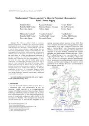
medical knowledge, our system aims (figure 1) to measure<br />
the pressure under the main acting zones of the foot<br />
during natural barefoot gait.<br />
Fig. 1. Our plantar pressure acquisition device with one shoe,<br />
one gauge conditioner and the PDA.<br />
This barefoot plantar pressure acquisition system is<br />
based on a medical shoe, which do not compress the foot<br />
and which sole welcomes several strain gauge sensors,<br />
and an acquisition modulus which is to be hold on the<br />
hips. The current acquisition modulus is compounded by a<br />
gauge conditioner and a PDA which volumes still have to<br />
be reduced.<br />
To analyse the results when using a piezoelectric sensors<br />
device, doctors first divide the plantar pressure<br />
distribution into areas of interest. Such a division is called<br />
a mask. Most masks found in publications use 8 areas<br />
([4], [7] and [8]).<br />
* : E-mail: fany.chedevergne@univ-fcomte.fr<br />
† : E-mail: marc.dahan@univ-fcomte.fr
12th <strong>IFToMM</strong> World Congress, Besançon (France), June18-21, 2007<br />
To make it easier to analyse <strong>for</strong> the doctors, our device<br />
only measures plantar pressures under the main acting<br />
zones of the foot during the gait. These zones are the heel,<br />
the external side, the metatarsal heads and the hallux. For<br />
example, <strong>for</strong> an adult our device contains eight sensors:<br />
two under the heel, two under the external side, three<br />
under the metatarsal heads and one under the hallux<br />
(figure 2).<br />
Fig. 2. Floor-sole of an equipped shoe <strong>for</strong> adult (8 sensors).<br />
Our device works as following. When walking, the foot<br />
compresses the <strong>for</strong>ce sensors against the floor: mechanical<br />
behavior. The compression changes the voltage passing<br />
through the strain gauge glued of the sensor: electronic<br />
in<strong>for</strong>mation. The voltage collected at the exit of the sensor<br />
is amplified be<strong>for</strong>e arriving to the PCMCIA acquisition<br />
card put in the PDA which will process the data. A<br />
software allows the PDA to show and to record the<br />
instantaneous voltage. After the walk, the data may be<br />
transferred to a computer and the pressure lines may be<br />
plotted.<br />
A. Mechanical Operation<br />
1 hallux sensor<br />
3 metatarsal heads sensors<br />
2 external side sensors<br />
2 heel sensors<br />
For volume reason, the proof body of the sensor has<br />
been chosen to be a dynamometric ring. A plane is made<br />
on the ring surface to determine a "standing position"<br />
when the ring stands on its plane.<br />
A metal case holds the ring in the standing position. The<br />
closing system allows the top surface of the case to slide<br />
down to compress the ring during the gait. It also allows a<br />
pre-strain on the ring to guaranty the permanent contact<br />
between the ring and the top and bottom of the case.<br />
Identically shaped holes in the soles receive the metal<br />
cases (eight per shoe in this example).<br />
Two aluminium plates, screwed on the top and at the<br />
bottom of the case, take in sandwich each sensor<br />
(figure 3).<br />
Fig. 3. Sensor assembly: a dynamometric ring placed inside a metal case<br />
taken in sandwich between two aluminium plates.<br />
When walking the foot pushes down the top aluminium<br />
plate and so the top of the case. The ring is so compressed<br />
against the bottom of the case. The latter lays on the<br />
bottom aluminium plate which lays on the floor. The sole<br />
does not interfere with the <strong>for</strong>ce transmission. The sole<br />
only keeps all the sensors linked together under the foot.<br />
Each sensor is equipped with a precision strain gauge<br />
(resistance of 350 Ohms) pasted on the external face and<br />
placed at the equator of the ring when the ring is standing<br />
on its plane (figure 4).<br />
12.5<br />
mm<br />
9.3<br />
mm<br />
Dynanometric ring<br />
Strain gauge<br />
Ring plane<br />
Fig. 4. Location of the strain gauge on the dynamometric ring<br />
in its standing position.<br />
During the highest pressure that may appear is twice the<br />
body weight according to [1] and [9], i.e. about 2000 N<br />
<strong>for</strong> an individual of 100 kg. Thus, to validate the elastical<br />
behaviour of our sensor during gait compression, we<br />
simulate the repetitive walking compressions using an<br />
Instron electromechanical universal testing system (6025<br />
INSTRON).<br />
We programmed 20 successive cycles of compression.<br />
Each cycle combined a compression <strong>for</strong> 0.4 s, a release<br />
<strong>for</strong> 0.4 s and a break off <strong>for</strong> 0.4 s. Thus, we simulated a<br />
1.2 s step, i.e. a "normal" speed step as revealed by [10].<br />
Each compression runned from 0 to 2000 N and back to<br />
0 N, because 2000 N should be the highest verticale <strong>for</strong>ce<br />
during the gait as previously noticed. Thus, the
12th <strong>IFToMM</strong> World Congress, Besançon (France), June18-21, 2007<br />
compression speed was 5000 N/s and each acquisition<br />
lasted 24 s. The chosen acquisition frequency was 100 Hz.<br />
We observed in figure 5 that during these 20 cycles the<br />
sensor keeps its elastic behaviour.<br />
with<br />
• a: ring width<br />
• E: ring Young modulus (elasticity)<br />
• F: ring submitted <strong>for</strong>ce<br />
• R: ring mean radius<br />
• t: ring thickness<br />
Thus, knowing all these parameters permit us to obtain<br />
the <strong>for</strong>ce (F) exerted on the ring by (3):<br />
2<br />
F 4V<br />
Eat / 3RK(<br />
V − 2V<br />
)(1 − 2 / Π)<br />
(3)<br />
=<br />
out<br />
in out<br />
Fig. 5. 20 cycles of gait mean speed compression<br />
of the sensor inserted into the shoe.<br />
The case allows a 0.5 mm vertical compression but the<br />
one of the ring does not exceed 0.15 mm at 2000N. Such<br />
sensor is thus validated <strong>for</strong> individuals until 100 kg.<br />
B. Electronic Operation<br />
The electronic operation is to translate the ring<br />
de<strong>for</strong>mation into the <strong>for</strong>ce exerted on the ring.<br />
A dual PCMCIA card expansion jacket allows the<br />
connection of two PCMCIA cards on the PDA iPAQ HP<br />
5500. Each PCMCIA acquisition card can record up to<br />
8 sensors.<br />
C. Data Acquisition<br />
A software has been developed in C++ language <strong>for</strong> the<br />
PDA to acquire the voltages and to record them on<br />
request.<br />
During acquisition, as well as during recording, the PDA<br />
may display the value of 16 sensors on the screen.<br />
The acquisition frequency can be chosen between 50<br />
and 500 Hz.<br />
Figure 7 presents the PDA screens of the software.<br />
Each sensor uses an extensiometric bridge. This bridge<br />
is a high sensibility Wheatston bridge in which one strain<br />
gauge is used instead of one resistance element. The strain<br />
gauge is said to be set in a quarter of bridge (figure 6).<br />
Vin<br />
Vout<br />
Fig. 6. Gauge set in quarter of bridge.<br />
The entry voltage in the bridge (V in ) is known and the<br />
exit one (V out ) is measured. The variation of this tension is<br />
due to the variation of the strain gauge resistance which<br />
translates its stretching (ε) as written in (1).<br />
−3 −6<br />
Vin / Vout<br />
= Kε × 10 /(4 + 2Kε<br />
× 10 ) (1)<br />
with K: strain gauge coefficient.<br />
On the other hand, the gauge de<strong>for</strong>mation during the<br />
ring compression may be known by the ring parameters<br />
(2) as written by [11] taken from [12].<br />
2<br />
ε = ( 1−<br />
2 / Π)<br />
× 3FR<br />
/ Eat<br />
(2)<br />
Fig. 7. Screens of the acquisition software on the PDA:<br />
the acquisition options screen (on the left) and<br />
the acquired sensor voltages screen (on the right).<br />
The PDA is belted on the patient hips so that individuals<br />
may go in any direction and with any movement without<br />
disturbance from connection wires.<br />
The recorded data are then transmitted to the main<br />
computer. These data are the voltage variations due to the
12th <strong>IFToMM</strong> World Congress, Besançon (France), June18-21, 2007<br />
strain of each sensor but they are not translated into the<br />
implied <strong>for</strong>ces. Figure 8 shows the example of a healthy<br />
adult walk: one step of one foot equipped with 8 sensors.<br />
% of BW<br />
Body weight (BW)<br />
Fig. 8. Curves of the 8 sensors strain in one shoe during one step.<br />
S1: internal heel ; S2: external heel ; S3: external rearfoot ; S4: external<br />
middle-foot; S5: fifth metatarsal head; S6: third metatarsal head ; S7:<br />
first metatarsal head; S8: hallux.<br />
Thus, we are in<strong>for</strong>med <strong>for</strong> each area of the foot about<br />
the moment of appearance of the pressure, the length of<br />
time of its increase, the moment of its maximum value, the<br />
length of time of its decreasing and the moment of its end.<br />
For example, the seventh sensor (S7) which is located<br />
under the head of the first metatarsus, begins to detect<br />
pressure at the sixth acquisition, the signal goes up until<br />
the fifteenth acquisition and then fall down until the<br />
eighteenth. Although this curve reaches the highest value<br />
of voltage, it does not mean that the implied <strong>for</strong>ce is the<br />
highest of all the sensors. These values aren't comparable<br />
between the sensors because the implied <strong>for</strong>ce values<br />
depend of the strain gauge coefficient of each sensor.<br />
Knowing the latter, we can indeed obtain the implied<br />
<strong>for</strong>ce using (3).<br />
Time<br />
Fig. 9. Plantar pressure distribution [13] and<br />
global vertical <strong>for</strong>ce curve and values (expressed in % of body weight)<br />
during the gait of a healthy individual.<br />
To identify the usual gait pattern of one patient, the<br />
latter is asked to walk <strong>for</strong> 10 meters on a line <strong>for</strong> 3 times.<br />
The five middle step of each walk are recorded. The mean<br />
of these 15 steps is calculated and then plotted like in<br />
figure 10.<br />
III. Medical process and Data Treatment Allowed by<br />
our <strong>Device</strong><br />
Our new device will permit to compare the patient<br />
plantar pressures to this healthy pattern. The foot-roll is<br />
part of a healthy gait plantar pressure pattern as well as<br />
the “camel back” shape of the vertical ground reaction<br />
<strong>for</strong>ce curve. These two parameters are well shown, in<br />
figure 9, by the evolution of the plantar pressure<br />
distribution and of the global vertical <strong>for</strong>ce during the<br />
gait.<br />
Fig. 10. Mean curves of the implied <strong>for</strong>ce calculated <strong>for</strong> each of the<br />
8 sensors of one shoe of one healthy patient (70 kg) during one step.<br />
(Mean upon 15 steps)
12th <strong>IFToMM</strong> World Congress, Besançon (France), June18-21, 2007<br />
Figure 10 clearly shows the foot-roll during one stance<br />
phase of gait.<br />
At the beginning of the stance phase (until the moment<br />
T1), the <strong>for</strong>ce of contact between the heel and the ground<br />
increases rapidly. It's the heel strike. The sensors S1 and<br />
S2 under the heel reach their highest value (respectively<br />
540 N and 430 N <strong>for</strong> this patient). During this phase, the<br />
other sensors are unloaded.<br />
During the "mid-stance" (T2), the <strong>for</strong>ce curves under<br />
heel and metatarsal heads show a medium level (300 N <strong>for</strong><br />
this patient). The foot is indeed flat on the floor and the<br />
pressure is spread all over the foot.<br />
Then the <strong>for</strong>ce increases under the <strong>for</strong>efoot until a peak<br />
at (T3) which occurs when the walker propels himself on<br />
the tip toe. The <strong>for</strong>ce under the first metatarsal head is up<br />
to 650 N <strong>for</strong> this patient.<br />
At T4, the <strong>for</strong>ces are zero. The toe off has occured and<br />
the foot has entered in oscillation.<br />
We also notice that the duration of this healthy stance<br />
phase is about one second.<br />
The healthy pattern should also includes the feet<br />
symmetric and repetitive pressures, i.e.:<br />
• same pressure under same area at the same relative<br />
phase of the stance period under both feet. That's to<br />
guaranty symmetry.<br />
• same pressure under same area at the same relative<br />
phase of the stance period under one same foot through<br />
several consecutive steps. That's to guaranty repetitivity.<br />
• touch of the foot beginning by the exclusive heel contact<br />
phase, following by a full foot period and finishing by an<br />
lonely <strong>for</strong>efoot phase.<br />
With our device, we could indeed also study the<br />
following variables suggested by [14]:<br />
• Velocity of the centre of pressure<br />
• Duration of the stance phase and contact times of the<br />
areas of interest.<br />
• Size of the contact area at a certain time point and<br />
maximum size.<br />
• Local peak and mean pressures underneath areas of<br />
interest.<br />
• Local peak and mean <strong>for</strong>ces underneath areas of interest.<br />
• Time until local pressure peak is reached.<br />
• Time until local <strong>for</strong>ce peak is reached.<br />
• Maximum loading rate of areas of interest.<br />
• Time to maximum loading rate of areas of interest.<br />
• Pressure-time integrals in areas of interest.<br />
• Force-time integrals in areas of interest.<br />
• Ratios such as one local pressure divided by another (or<br />
the sum of some local pressures divided by the sum of<br />
others) or relative pressure-time integrals dividing a<br />
pressure-time integral by the sum of all pressure-time<br />
integrals, etc.<br />
• Differences concerning the same variable between two<br />
different locations.<br />
Thus, we can identify the wrong plantar pressure<br />
patterns due to the numerous injuries and deceases<br />
affecting the musculoskeletal system.<br />
IV. Conclusion and Perspectives<br />
This article has presented a new mechatronical device<br />
which measures plantar pressures during the gait so that<br />
the doctors may detect or prevent gait injuries and<br />
deceases.<br />
When walking, the foot of the patient compresses the<br />
dynamometric rings inserted into the sole of the shoe. This<br />
de<strong>for</strong>mation is translated by a strain gauge into a voltage<br />
variation. This in<strong>for</strong>mation is recorded by a personal<br />
digital assistant (PDA) belt on the patient hips. And<br />
finally, the data is plotted on a main computer to show the<br />
plantar pressure evolution under the main acting zones of<br />
the foot.<br />
As written by [15], our sensor is not a very thickness<br />
sensor, but it has just the dimension of a standard shoe<br />
sole. It offers a great longevity, linearity and precision.<br />
Instead of many systems of instrumented shoes, the fact<br />
that the sensor is integrated in the sole did not marked<br />
prominence under the shoe; also the walker does not<br />
observed alteration of gait or discom<strong>for</strong>t. There<strong>for</strong>e, the<br />
shape of the soft sole, divided in eight rigid areas, does<br />
not perturb the natural roll of the foot on the ground.<br />
The preparation of the sole to receive each sensor (hole<br />
pre pierced) and the possibility of easy installation and<br />
manipulation, authorizes the use of the same sensor <strong>for</strong><br />
different shoe sizes and <strong>for</strong> several areas of the sole.<br />
Compared to a <strong>for</strong>ce plate, our instrumented shoes<br />
system permits a recording of plantar dynamic along a<br />
great number of steps; and the use of these shoes cancels<br />
the walker anxiety relating to foot placement frequently<br />
observed in a walk on a limited single <strong>for</strong>ce plate.<br />
Instead of the plantar pressure insole which takes<br />
pressure with the artefact of the shoes, our instrumented<br />
shoes authorize the recording of plantar pressure and <strong>for</strong>ce<br />
acting directly at the foot-ground interface. Because the<br />
sole of the shoe does not absorb the <strong>for</strong>ce in order to<br />
allow doctors to analyse the barefoot walking pressures of<br />
their patients. Such in<strong>for</strong>mation may help to detected<br />
present locomotion injuries or illness and to predict the<br />
future ones. Moreover, our product gives only locally<br />
identified pressure to make the analysis easier. And, last<br />
but not least, our sensors have longer life expectancy.<br />
Regarding the dynamometric treadmill [16], our<br />
instrumented shoes are cheaper, portable and permit a<br />
natural walking.<br />
This instrumented shoe is a robust tool to assess the<br />
instantaneous vertical <strong>for</strong>ces and plantar pressures exerted
12th <strong>IFToMM</strong> World Congress, Besançon (France), June18-21, 2007<br />
during gait over a great number of steps. It offers an<br />
objective, low cost documentation of healthy and<br />
pathological subject gait.<br />
The tests realised on the gait of healthy subjects and the<br />
data obtained encourage us to continue the validation of<br />
this tool.<br />
Although this mechatronical device is medically helpful,<br />
some optimisation is still required.<br />
The sensor sensitivity could be better. We will decrease<br />
the ring width so that a same pressure will be translated by<br />
a bigger voltage variation.<br />
We also want to develop wireless communication<br />
between the PDA and the main computer so that the data<br />
may be transfered instantaneously and the pressure line<br />
may appear instantaneously too.<br />
References<br />
[1] Perttunen J. Foot loading in normal and pathological walking. Ph.D.<br />
thesis, University of Jyvaskyla, 2002.<br />
[2] Kowalski C. Petit livre rouge du pied, 2000.<br />
[3] Kogler G.F. and Shorten M.R. Plantar pressure distribution during<br />
gait in a subject without adipose tissue in the heel and ball of the<br />
foot. In Proc. of the 5th Symp. on Footwear Biomechanics, pages<br />
56-57, Zuerich, Switzerland, Eds. E. Hennig, A. Stacoff, 2001.<br />
[4] Becker H.P., Rosenbaum D., Claes L. and Gerngro H. Measurement<br />
of plantar pressure distribution during gait <strong>for</strong> diagnosis of<br />
functional lateral ankle instability. In The Fifth EMED User<br />
Meeting, 1996.<br />
[5] Bleau J. L'evaluation de la marche. In Optimum, 5(1): 1-8, 1994.<br />
[6] Haumont T. Analyse quantifiée de la marche et pied bot en fin de<br />
croissance. In AFCP, November 2003.<br />
[7] Hennig E. M. and Milani T. L. In-shoe pressure distribution <strong>for</strong><br />
running in various types of footwear. In Journal of Applied<br />
Biomechanics, 11(3): 299-310, 1995.<br />
[8] Bisiaux M., Moretto P., Lensel G. and Thévenon A. Determination<br />
of an expected plantar pressure threshold: dimensionless approach<br />
use to reduce the variability of the plantar pressures. In Annals of<br />
readaptation and physical medecine, 46: 539-544, 2003.<br />
[9] Lampe R. Influence of orthopaedic technical aid on the kinematics<br />
and kinetics of the knee joint. In Brain and Development, 26: 219-<br />
226, 2004.<br />
[10] Viel E. La marche humaine, la course et le saut, Paris, Masson,<br />
2000.<br />
[11] Faivre A. Conception et validation d'un nouvel outil d'analyse<br />
clinique de la marche. Ph.D. thesis, University of Franche-Comte,<br />
2003.<br />
[12] Goer J.L. Le and Avril J. Capteurs a jauges extensiometriques. In<br />
Techniques de l'ingenieur - Mesures mecaniques et dimensionnelle,<br />
RD2, Avril 1992.<br />
[13] Lecuyer C. Données de références de la marche chez le sujet sain<br />
sur tapis dynamométrique ADAL 3D. Master thesis, University of<br />
Franche-Comte, 2002.<br />
[14] Hagman F. Can plantar pressure predict foot motion. Ph.D. thesis,<br />
Technical University of Eindhoven, 2005.<br />
[15] Faivre A., Dahan M., Paratte B., Monnier G. Instrumented shoe <strong>for</strong><br />
pathological gait assessment. In Mechanics Research<br />
Communications, 31: 627-632, 2004.<br />
[16] Belli A., Bui P., Berger A., Geyssant A., Lacour J.R. A treadmill<br />
ergometer <strong>for</strong> three-dimensional ground reaction <strong>for</strong>ces<br />
measurement during walking. In Journal of Applied Biomechanics,<br />
34: 105-112, 2001.