Multi-body Dynamics Simulation on Flexible Crankshaft ... - IFToMM
Multi-body Dynamics Simulation on Flexible Crankshaft ... - IFToMM
Multi-body Dynamics Simulation on Flexible Crankshaft ... - IFToMM

Create successful ePaper yourself
Turn your PDF publications into a flip-book with our unique Google optimized e-Paper software.
12th <strong>IFToMM</strong> World C<strong>on</strong>gress, Besanç<strong>on</strong> (France), June18-21, 2007<br />
<str<strong>on</strong>g>Multi</str<strong>on</strong>g>-<str<strong>on</strong>g>body</str<strong>on</strong>g> <str<strong>on</strong>g>Dynamics</str<strong>on</strong>g> <str<strong>on</strong>g>Simulati<strong>on</strong></str<strong>on</strong>g> <strong>on</strong> <strong>Flexible</strong> <strong>Crankshaft</strong> System<br />
Ma Xingguo 1 You Xiaomei 2 Wen Bangchun 3<br />
Northeastern University 1 Shenyang LiG<strong>on</strong>g University Northeastern University<br />
Shenyang LiG<strong>on</strong>g University 2 Shenyang ,China Shenyang ,China<br />
Shenyang ,China<br />
Abstract—A virtual prototype of flexible multi-<str<strong>on</strong>g>body</str<strong>on</strong>g><br />
crankshaft system of engine is used to do the dynamics<br />
simulati<strong>on</strong>. The theory of flexible multi-<str<strong>on</strong>g>body</str<strong>on</strong>g> systems dynamics is<br />
combined with FEA method to study the crankshaft, the dynamic<br />
boundary loads <strong>on</strong> the joints in a working cycle are determined<br />
by the simulati<strong>on</strong> <strong>on</strong> the crankshaft system. The real-time<br />
dynamics resp<strong>on</strong>se of the crankshaft in a cycle is achieved. It<br />
provides an important foundati<strong>on</strong> for the crankshaft optimum<br />
design. <br />
Keywords: crankshaft, engine, dynamics, multi-<str<strong>on</strong>g>body</str<strong>on</strong>g><br />
I. Foreword<br />
<strong>Crankshaft</strong>-mechanism of engine works in HTHP<br />
envir<strong>on</strong>ment. <strong>Crankshaft</strong> acted by the alternating loads<br />
endures different loads such as compress, stretch, bent and<br />
torsi<strong>on</strong>, so its intensity and rigidity must be guaranteed in<br />
design. <strong>Crankshaft</strong> is a key part of engine, its mechanical<br />
property directly influence <strong>on</strong> the reliability and l<strong>on</strong>gevity<br />
of engine. At present, simplified models are mostly used<br />
in methods of the stress analysis of the crankshaft. The<br />
method are limited to <strong>on</strong>e moment, does not deal with the<br />
whole working process, and cannot be used to accurately<br />
determine the stress state <strong>on</strong> the real working process of<br />
crankshaft. In recent years, the development of the virtual<br />
prototype technology and the flexible multi-<str<strong>on</strong>g>body</str<strong>on</strong>g><br />
dynamics theory make it come true to know the real-time<br />
dynamics resp<strong>on</strong>se of the crankshaft.<br />
II. The Method of <str<strong>on</strong>g>Multi</str<strong>on</strong>g>-<str<strong>on</strong>g>body</str<strong>on</strong>g> <str<strong>on</strong>g>Dynamics</str<strong>on</strong>g> <str<strong>on</strong>g>Simulati<strong>on</strong></str<strong>on</strong>g><br />
Analysis <strong>on</strong> <strong>Flexible</strong> <strong>Crankshaft</strong> System<br />
The modelling of a virtual prototype of crankshaft system,<br />
c<strong>on</strong>stituted by crankshaft, link, pist<strong>on</strong> and so <strong>on</strong>, has three<br />
steps. First, the three-dimensi<strong>on</strong>al model of these parts are<br />
built in modeling software. Sec<strong>on</strong>d, they are transferred to<br />
ADAMS, the multi-<str<strong>on</strong>g>body</str<strong>on</strong>g> dynamics analysis software.<br />
Finally, the kinematical pairs are simplified to the ideal<br />
c<strong>on</strong>straint used in the dynamics simulati<strong>on</strong>. The flexibility<br />
acti<strong>on</strong> of the crankshaft has very important influence <strong>on</strong><br />
the dynamics characteristic of the whole engine. In order<br />
to c<strong>on</strong>sider the elastic deformati<strong>on</strong> of crankshaft, a<br />
relative descripti<strong>on</strong> method is adopted to create the<br />
1 mxg@mail.edu.cn<br />
2 prime_queen@163.com<br />
3 bcwen1930@sina.com<br />
flexible model of crankshaft, then the moti<strong>on</strong> of<br />
crankshaft can be disassembled as implicati<strong>on</strong> movement<br />
of rigid crankshaft and deformati<strong>on</strong> of flexible crankshaft<br />
relative to the moving reference frame. The deformati<strong>on</strong> is<br />
described by modal vector and modal coordinates, that<br />
is [1] :<br />
u f<br />
= φ ⋅ q η<br />
φ= [φ1 φ2 … ф N ], φ is matrix of modal vector,q η =<br />
q η ,t,, q η is modal coordinates, N is the number of modal<br />
vector.<br />
Modal analysis is achieved by ANSYS, and a modal<br />
neutral file (.MNF) can be gotten. Then the file can be<br />
input directly into ADAMS to create the flexible model.<br />
Furthermore, the model of multi-<str<strong>on</strong>g>body</str<strong>on</strong>g> dynamics system<br />
including the flexible crankshaft can be used to do<br />
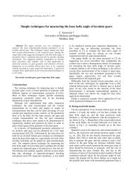
dynamics simulati<strong>on</strong>. The analysis flow is shown in Fig.1<br />
.<br />
Fig.1 The flow of simulati<strong>on</strong> <strong>on</strong> multi-<str<strong>on</strong>g>body</str<strong>on</strong>g> dynamics system with<br />
flexible crankshaft<br />
III. The Example of <str<strong>on</strong>g>Multi</str<strong>on</strong>g>-<str<strong>on</strong>g>body</str<strong>on</strong>g> System <str<strong>on</strong>g>Simulati<strong>on</strong></str<strong>on</strong>g> of<br />
<strong>Crankshaft</strong><br />
A. The Model of <str<strong>on</strong>g>Multi</str<strong>on</strong>g>-rigid Body <str<strong>on</strong>g>Dynamics</str<strong>on</strong>g><br />
The model of multi-rigid <str<strong>on</strong>g>body</str<strong>on</strong>g> system of the crankshaft of<br />
some V8 engine is created in ADAMS. The model is<br />
shown in Fig3. The movement discipline of every part can<br />
be determined by simulating. Interacti<strong>on</strong> forces between<br />
parts, centralized forces of the nodes, can be determined<br />
also. The model can be also used to do analysis for<br />
balance of engine.
12th <strong>IFToMM</strong> World C<strong>on</strong>gress, Besanç<strong>on</strong> (France), June18-21, 2007<br />
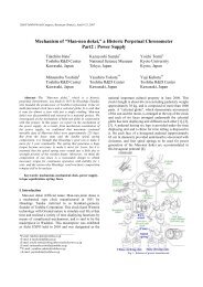
Fig.2 the multi-rigid <str<strong>on</strong>g>body</str<strong>on</strong>g> dynamics model of crankshaft system<br />
C. Results of <strong>Flexible</strong> <str<strong>on</strong>g>Multi</str<strong>on</strong>g>-<str<strong>on</strong>g>body</str<strong>on</strong>g> <str<strong>on</strong>g>Dynamics</str<strong>on</strong>g> <str<strong>on</strong>g>Simulati<strong>on</strong></str<strong>on</strong>g> of<br />
The <strong>Crankshaft</strong> System<br />
Distributi<strong>on</strong> of stress <strong>on</strong> real time of the crankshaft system<br />
in a cycle, as shown in Fig.5, can be determined by the<br />
simulati<strong>on</strong>. According to the igniti<strong>on</strong> order of engine and<br />
by putting a rotati<strong>on</strong>, whose rev is equal to rated speed of<br />
engine, <strong>on</strong> the crankshaft. The simulati<strong>on</strong> is achieved by<br />
applying burst gas pressure <strong>on</strong> the pist<strong>on</strong>s and transferring<br />
the pressure to flexible crankshaft. The dangerous area of<br />
crankshaft in a working cycle can be estimated.<br />
B. The <str<strong>on</strong>g>Multi</str<strong>on</strong>g>-<str<strong>on</strong>g>body</str<strong>on</strong>g> System Model of <strong>Crankshaft</strong> System<br />
with <strong>Flexible</strong> <strong>Crankshaft</strong><br />
Modal analysis of the crankshaft is d<strong>on</strong>e <strong>on</strong> crankshaft<br />
finite element model, and a modal neutral file (.MNF) is<br />
created when Craig-Bampt<strong>on</strong> modal is orthog<strong>on</strong>alized <strong>on</strong><br />
free modal. The flexible crankshaft is created by<br />
transferring the MNF to ADAMS. The finite element<br />
model of the crankshaft created in ANSYS is shown in<br />
Fig.3.<br />
Fig.5 distributi<strong>on</strong> of stress of the crankshaft<br />
Fig.3 finite element model of the crankshaft<br />
The other parts in crankshaft system just transfer the burst<br />
gas pressures and inertia forces in work, so multi-<str<strong>on</strong>g>body</str<strong>on</strong>g><br />
system model can be built as multi-rigid <str<strong>on</strong>g>body</str<strong>on</strong>g> system<br />
model at first, that means all parts can be built as rigid<br />
<str<strong>on</strong>g>body</str<strong>on</strong>g>. The flexible multi-<str<strong>on</strong>g>body</str<strong>on</strong>g> system model, as shown in<br />
Fig.4, can be built by replacing the rigid crankshaft with<br />
flexible crankshaft.<br />
The dynamic boundary load (.lod file) <strong>on</strong> the joints of<br />
crankshaft system in a working cycle can be determined<br />
by the simulati<strong>on</strong> of flexible multi-<str<strong>on</strong>g>body</str<strong>on</strong>g> dynamics. The<br />
c<strong>on</strong>centrated load, determined by the multi-rigid <str<strong>on</strong>g>body</str<strong>on</strong>g><br />
dynamics simulati<strong>on</strong>, can be dispersed <strong>on</strong> the finite<br />
element nodes of the joint surface. The dispersible loads<br />
express the real load boundary c<strong>on</strong>diti<strong>on</strong>s. Then, an<br />
accurate transient dynamics resp<strong>on</strong>se analysis <strong>on</strong> the<br />
crankshaft can be achieved.<br />
D. Transient <str<strong>on</strong>g>Dynamics</str<strong>on</strong>g> Resp<strong>on</strong>se Analysis of The<br />
<strong>Crankshaft</strong><br />
After the multi-<str<strong>on</strong>g>body</str<strong>on</strong>g> dynamics simulati<strong>on</strong> in ADAMS,<br />
accurate dynamics resp<strong>on</strong>se <strong>on</strong> real time in a cycle of the<br />
crankshaft is achieved in ANSYS. The dynamic boundary<br />
loads of crankshaft system is c<strong>on</strong>sidered as boundary<br />
c<strong>on</strong>diti<strong>on</strong> in ANSYS, the dynamic loads are applied <strong>on</strong> the<br />
crankshaft to do a transient dynamic resp<strong>on</strong>se analysis.<br />
Moreover, the precise real time stress distributi<strong>on</strong> of the<br />
crankshaft can be determined, as shown in Fig.6.<br />
The stress value and its distributi<strong>on</strong> of the crankshaft<br />
determined by simulati<strong>on</strong> analysis are close to test results,<br />
which can infer that the results of simulati<strong>on</strong> are reliable.<br />
Fig.4 the multi-<str<strong>on</strong>g>body</str<strong>on</strong>g> dynamics model of crankshaft system with flexible<br />
crankshaft
12th <strong>IFToMM</strong> World C<strong>on</strong>gress, Besanç<strong>on</strong> (France), June18-21, 2007<br />
1<br />
Ma Xingguo is a doctor of mechanical design and theory of<br />
Northeastern University , a professor of Shenyang LiG<strong>on</strong>g University, a<br />
visiting scholar in the University of Tampere Polytechnic, owner of<br />
Chinese government special allowance, winner of the “Famous Teacher”<br />
of Lia<strong>on</strong>ing Province, in charge of the research project of multi-<str<strong>on</strong>g>body</str<strong>on</strong>g><br />
dynamics simulati<strong>on</strong> and engine.<br />
2 You Xiaomei, lectuer of Shenyang LiG<strong>on</strong>g University, engage in<br />
multi-<str<strong>on</strong>g>body</str<strong>on</strong>g> dynamics simulati<strong>on</strong> and mechanical vibrati<strong>on</strong>.<br />
3<br />
Wen Bangchun , academician of the Chinese Academy of Sciences.<br />
Professor of mechanical engineering and automati<strong>on</strong> of Northeastern<br />
University, h<strong>on</strong>orary chairman of the Chinese Vibrati<strong>on</strong> Engineering<br />
Society.<br />
Fig.6 the distributi<strong>on</strong> at the maximum stress moment of crankshaft<br />
IV. C<strong>on</strong>clusi<strong>on</strong><br />
(1) The flexible multi-<str<strong>on</strong>g>body</str<strong>on</strong>g> dynamics simulati<strong>on</strong> is based<br />
<strong>on</strong> the crankshaft system or a virtual prototype, it can<br />
simulate mechanical behaviour of crankshaft of engine in<br />
real working c<strong>on</strong>diti<strong>on</strong>. Comparing to the comm<strong>on</strong><br />
analysis method about individual crankshaft, this method<br />
has three obvious advantages. Firstly, the system model is<br />
more approach to the physical prototype. Sec<strong>on</strong>dly, it<br />
need less hypothesis. Thirdly, it faces to process rather<br />
than moment, thus this method has higher analysis<br />
precisi<strong>on</strong>.<br />
(2) The centralized force of joint can be dispersed to the<br />
joint’nodes of finite element model by the flexible multi<str<strong>on</strong>g>body</str<strong>on</strong>g><br />
dynamic analysis. This method can determine the<br />
real-time dynamic loads exactly and provide the real load<br />
boundary c<strong>on</strong>diti<strong>on</strong> for the analysis in ANSYS.<br />
(3) The transient dynamics resp<strong>on</strong>se can be achieved in<br />
ANSYS with dynamic loads, which can be used to<br />
determine the dangerous area of the crankshaft in a<br />
working cycle and to evaluate the mechanical property of<br />
the crankshaft quantificati<strong>on</strong>ally.<br />
In c<strong>on</strong>clusi<strong>on</strong>, the method, combined FEA with flexible<br />
multi-<str<strong>on</strong>g>body</str<strong>on</strong>g> dynamics analysis, is of great significance for<br />
predicting dynamic characteristics of engine structure and<br />
for optimizati<strong>on</strong> of key parts in design stage.<br />
References<br />
[1] Lu You-Fang. <strong>Flexible</strong> multi-<str<strong>on</strong>g>body</str<strong>on</strong>g> dynamics[M]. Beijing : Higher<br />
Educati<strong>on</strong> Press, 1996<br />
[2] DING Neng-Gen,LIAN Bao-Xu. CAE applicati<strong>on</strong> development<br />
and practice in the car. Computer-aided design and<br />
manufacturing. 2000,6<br />
[3] YU Cheng-Bo,HE Huai-Bo. Engine vibrati<strong>on</strong> c<strong>on</strong>trol and<br />
applicati<strong>on</strong> [M]. Beijing : Nati<strong>on</strong>al Defense Industry Press, 1997<br />
[4] ADAMS User's Reference Manual.. versi<strong>on</strong> 8.0.MDI,1994<br />
[5] C<strong>on</strong>nelly J D, Hust<strong>on</strong> R L. The dynamics of flexible multi<str<strong>on</strong>g>body</str<strong>on</strong>g><br />
systems: A finite segment approach——I. Theoretical<br />
aspects[J].Computers and Structures,1994,50(2):255-258<br />
[6] LuJiqing, Shen Zujing, K<strong>on</strong>g Xianqing ,et al. Design of vehicle<br />
engine[M]Beijing: Tsinghua University Press,1993.(In Chinese)