Research and Development of Cone to Cone Type CVT - IFToMM
Research and Development of Cone to Cone Type CVT - IFToMM
Research and Development of Cone to Cone Type CVT - IFToMM

Create successful ePaper yourself
Turn your PDF publications into a flip-book with our unique Google optimized e-Paper software.
12th <strong>IFToMM</strong> World Congress, Besançon (France), June18-21, 2007<br />
CK-xxx<br />
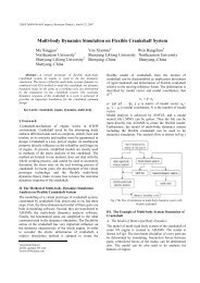
<strong>Research</strong> <strong>and</strong> <strong>Development</strong> <strong>of</strong> <strong>Cone</strong> <strong>to</strong> <strong>Cone</strong> <strong>Type</strong> <strong>CVT</strong><br />
H. Komatsubara * T. Yamazaki † S. Kuribayashi ‡<br />
Yamagata University Yamagata University Kuribayashi Steamship<br />
Yamagata, Japan Yamagata, Japan Tokyo, Japan<br />
Abstract— 1 Traction drive <strong>CVT</strong> is a low noise <strong>and</strong> a low<br />
vibration. But most <strong>of</strong> traction drive <strong>CVT</strong> have complex structure.<br />
One <strong>of</strong> the authors invented a new type <strong>of</strong> traction drive <strong>CVT</strong>. As<br />
for this new <strong>CVT</strong>, the structure is simple, <strong>and</strong> transfer efficiency<br />
is high. This new <strong>CVT</strong> is called <strong>Cone</strong> <strong>to</strong> <strong>Cone</strong> <strong>Type</strong> <strong>CVT</strong>(CTC-<br />
<strong>CVT</strong>). The purpose <strong>of</strong> this research aimed at practical use <strong>of</strong><br />
CTC-<strong>CVT</strong> In this report, first the structure <strong>and</strong> the speed<br />
changing mechanism <strong>of</strong> CTC-<strong>CVT</strong> is examined. Secondly, the<br />
design <strong>of</strong> CTC-<strong>CVT</strong> is described. Finally, the mechanical<br />
efficiency <strong>of</strong> power transmission is examined.<br />
Keywords: machine element, tribology, lubrication, <strong>CVT</strong>,<br />
traction drive, efficiency<br />
I. Introduction<br />
In the traction drive, mechanical power is transmitted<br />
between two ro<strong>to</strong>rs via an elas<strong>to</strong>hydrodynamic lubrication<br />
(EHL) oil film. The traction oil intervening between the<br />
ro<strong>to</strong>rs forms an oil film when it experiences a pressing<br />
force, <strong>and</strong> it transmits mechanical power by the shear<br />
force (traction force) <strong>of</strong> this oil film. The traction drive is<br />
low vibration <strong>and</strong> low noise <strong>and</strong> has the feature <strong>of</strong> being<br />
able <strong>to</strong> make up a continuously variable transmission<br />
(<strong>CVT</strong>). For the traction drive type <strong>CVT</strong>, various structures<br />
have been developed. Ring-corn type <strong>CVT</strong> [1] <strong>and</strong> kopp<br />
type <strong>CVT</strong> [2] have been applied <strong>to</strong> industrial machine.<br />
Half-<strong>to</strong>roidal <strong>CVT</strong> has been practically used for<br />
au<strong>to</strong>mobiles [3]. Power transmission efficiency <strong>of</strong> this<br />
<strong>CVT</strong> is over 92 [%] [4]. In addition, shaft drive <strong>CVT</strong> [5]<br />
<strong>and</strong> full-<strong>to</strong>roidal <strong>CVT</strong> [6] have been studied. However,<br />
the <strong>CVT</strong> <strong>of</strong> this traction drive type has a narrow range <strong>of</strong><br />
reduction ratio <strong>and</strong> the structure is complex.<br />
Thus, Kuribayashi, one <strong>of</strong> the authors, devised a <strong>CVT</strong><br />
using cones in the traction drive type <strong>CVT</strong>, whose<br />
structure is simple <strong>and</strong> from which a high reduction ratio<br />
is available[7]. Figure 1 shows a schematic <strong>of</strong> the power<br />
transmission portion <strong>of</strong> the devised <strong>CVT</strong>. Figure 2 shows<br />
an exploded perspective view <strong>of</strong> the power transmission<br />
portion. In this <strong>CVT</strong>, intermediate rolling elements are<br />
placed between the input <strong>and</strong> output shafts <strong>to</strong> transmit<br />
mechanical power. The input <strong>and</strong> output shafts have a<br />
concave conical form, <strong>and</strong> the intermediate rolling<br />
elements have a convex conical form. Because mechanical<br />
power is transmitted from cone <strong>to</strong> cone, this new <strong>CVT</strong> is<br />
called the cone-<strong>to</strong>-cone type <strong>CVT</strong> (CTC-<strong>CVT</strong>). On the<br />
input <strong>and</strong> output shafts, gears are attached at the shaft end<br />
as shown in Figure 2. By attaching the gears, the number<br />
<strong>of</strong> mating parts <strong>of</strong> the input <strong>and</strong> output shafts <strong>and</strong> the<br />
rolling elements can be increased. By increasing the<br />
number <strong>of</strong> mating parts <strong>of</strong> the input <strong>and</strong> output shafts <strong>and</strong><br />
the rolling elements, high <strong>to</strong>rque can be transmitted.<br />
This study aims at practical development <strong>of</strong> CTC-<strong>CVT</strong><br />
which simple structure parts <strong>and</strong> power transmission<br />
efficiency is about 90 [%]. This time, <strong>to</strong> know the basic<br />
characteristics <strong>of</strong> the CTC-<strong>CVT</strong>, one set <strong>of</strong> input <strong>and</strong><br />
output shafts <strong>and</strong> rolling elements was examined without<br />
attaching gears at the input <strong>and</strong> output shaft ends.<br />
First the structure <strong>and</strong> speed-changing mechanism <strong>of</strong><br />
the CTC-<strong>CVT</strong> are described. Finally, the design <strong>and</strong><br />
power transmission efficiency examination <strong>of</strong> a pro<strong>to</strong>type<br />
are presented.<br />
Fig. 1. Schematic <strong>of</strong> CTC-<strong>CVT</strong><br />
*E-mail: hkomatsu@yz.yamagata-u.ac.jp<br />
† E-mail: am01137@dipfr.dip.yz.yamagata-u.ac.jp<br />
‡ E-mail: a.kotani@kuribayashi.co.jp<br />
Fig. 2. Exploded perspective view <strong>of</strong> CTC-<strong>CVT</strong>
12th <strong>IFToMM</strong> World Congress, Besançon (France), June18-21, 2007<br />
CK-xxx<br />
II. Basic Structure<br />
A. Structure <strong>of</strong> CTC-<strong>CVT</strong><br />
Figure 3 shows a schematic <strong>of</strong> the power transmission<br />
portion <strong>of</strong> the CTC-<strong>CVT</strong>. This CTC-<strong>CVT</strong> is composed <strong>of</strong><br />
input <strong>and</strong> output shafts <strong>and</strong> an intermediate rolling<br />
element inscribed between them. The input <strong>and</strong> output<br />
shafts have a concave conical form, <strong>and</strong> the intermediate<br />
rolling element has a convex conical form. An <strong>of</strong>fset <strong>of</strong> E<br />
is given between the input <strong>and</strong> output shafts. Traction oil<br />
intervenes between the concave cone at the end <strong>of</strong> each<br />
shaft <strong>and</strong> the convex cone <strong>of</strong> the intermediate rolling<br />
element, <strong>and</strong> it forms an oil film when a pressing force is<br />
applied from the input shaft side. A traction force is<br />
produced by the oil film, <strong>and</strong> the rotation <strong>of</strong> the input shaft<br />
is transmitted <strong>to</strong> the output shaft via the intermediate<br />
rolling element. Speed changes are effected by changing<br />
the contact radius <strong>of</strong> the intermediate rolling element, <strong>and</strong><br />
the radius change is in turn effected by translating the<br />
intermediate rolling element obliquely along the cone<br />
angle.<br />
B. Speed-changing Mechanism<br />
The CTC-<strong>CVT</strong> changes the speed smoothly by<br />
translating the intermediate rolling element obliquely<br />
along the cone angle. Figure 4 shows the geometry <strong>of</strong> the<br />
power transmission portion. Letting r 1 be the corotation<br />
radius <strong>of</strong> the input shaft, r 2 be the corotation radius <strong>of</strong> the<br />
convex cone on the input side, ω 1 be the angular velocity<br />
<strong>of</strong> the input shaft, <strong>and</strong> ω 2 be the angular velocity <strong>of</strong> the<br />
rolling element, then the following relationship is obtained<br />
on the input side.<br />
r<br />
1ω1<br />
= r2ω<br />
2<br />
(1)<br />
Letting r 3 be the corotation radius <strong>of</strong> the convex cone<br />
on the output side, r 4 be the corotation radius <strong>of</strong> the output<br />
shaft, <strong>and</strong> ω 3 be the angular velocity <strong>of</strong> the output shaft,<br />
then the following relationship is obtained on the output<br />
side.<br />
r<br />
3ω2<br />
= r4ω<br />
3<br />
(2)<br />
The reduction ratio, e, is the ratio <strong>of</strong> the angular<br />
velocity <strong>of</strong> the input shaft <strong>to</strong> that <strong>of</strong> the output shaft <strong>and</strong> is<br />
given by the following equation using Equations 1 <strong>and</strong> 2.<br />
ω1<br />
ω1<br />
ω2<br />
r2<br />
r4<br />
e = = ⋅ = (3)<br />
ω3<br />
ω2<br />
ω3<br />
r3<br />
r1<br />
If the corotation radii, r 1 <strong>and</strong> r 4 , <strong>of</strong> the input <strong>and</strong> output<br />
r 2 =2r 3 r 2 =r 3<br />
shafts are equal, the following equation is obtained.<br />
e = r 2<br />
r 3<br />
(4)<br />
If the convex cone is translated, the corotation radii r 2<br />
<strong>and</strong> r 3 <strong>of</strong> the intermediate rolling element at the points <strong>of</strong><br />
contact respectively with the input <strong>and</strong> output shafts<br />
change. As shown in Figure 5(a), the reduction ratio is<br />
2.0 if the length <strong>of</strong> r 2 is twice the length <strong>of</strong> r 3 . It is 1.0 if<br />
the length <strong>of</strong> r 2 is equal <strong>to</strong> the length <strong>of</strong> r 3 (Figure 5(b)).<br />
Likewise, the reduction ratio is 0.5 if the length <strong>of</strong> r 2 is<br />
half the length <strong>of</strong> r 3 (Figure 5(c)). Thus, when the<br />
corotation radii <strong>of</strong> the intermediate rolling element change,<br />
the reduction ratio changes according <strong>to</strong> Equations 3 <strong>and</strong> 4.<br />
Fig. 3. Schematic <strong>of</strong> power transmission portion<br />
Fig. 4. Geometrical parameters <strong>of</strong> CTC-<strong>CVT</strong><br />
III. Design <strong>of</strong> CTC-<strong>CVT</strong> Pro<strong>to</strong>type<br />
To verify the operation <strong>and</strong> performance <strong>of</strong> the CTC-<br />
<strong>CVT</strong>, a CTC-<strong>CVT</strong> pro<strong>to</strong>type was designed. Figure 6<br />
shows a sectional view <strong>of</strong> the designed CTC-<strong>CVT</strong>. Table<br />
1 shows the specifications for the designed CTC-<strong>CVT</strong><br />
pro<strong>to</strong>type.<br />
As a design condition, a mo<strong>to</strong>r with a rated capacity <strong>of</strong><br />
15 [kw] <strong>and</strong> a rotational speed <strong>of</strong> 1500 [rpm] was used as<br />
the input power source. The design was done on the<br />
design concept <strong>of</strong> attaining a pro<strong>to</strong>type with high power<br />
transmission efficiency.<br />
For changing the speed, a mechanism <strong>to</strong> translate the<br />
r 2 =r 3 /2<br />
(a) e=2.0 (b) e=1.0 (c) e=0.5<br />
Fig. 5. Reduction ratio change mechanism <strong>of</strong> CTC-<strong>CVT</strong>
12th <strong>IFToMM</strong> World Congress, Besançon (France), June18-21, 2007<br />
CK-xxx<br />
intermediate rolling element along the cone angle by<br />
turning a h<strong>and</strong>le was used. Figure 7 shows a schematic <strong>of</strong><br />
the transmission mechanism. A case supports the<br />
intermediate rolling element, <strong>and</strong> a slider is attached <strong>to</strong> the<br />
case. A groove is cut in the frame at the same angle as the<br />
convex cone. A h<strong>and</strong>le is attached on the <strong>to</strong>p <strong>of</strong> the case,<br />
<strong>and</strong> turning the h<strong>and</strong>le translates the case along the groove<br />
<strong>and</strong> can effect stepless speed changes.<br />
The pressure force necessary for the traction drive is<br />
given by the loading cam on the input shaft side. The<br />
loading cam is a device <strong>to</strong> produce a pressing force<br />
according <strong>to</strong> the input <strong>to</strong>rque. For the bearings on the<br />
input <strong>and</strong> output shafts, a duplex angular bearing <strong>and</strong><br />
roller bearing are used. The bearings <strong>of</strong> the CTC-<strong>CVT</strong><br />
experience radial <strong>and</strong> thrust loads. These bearings are<br />
used as a combination that can carry these loads <strong>and</strong> cause<br />
little power loss at the bearings. The <strong>CVT</strong> was designed<br />
so that the duplex angular bearing will carry radial <strong>and</strong><br />
thrust loads <strong>and</strong> the roller bearing will carry a large radial<br />
load. The distance between the bearings was decided in<br />
consideration <strong>of</strong> the allowable angle <strong>and</strong> efficiency <strong>of</strong> the<br />
bearings.<br />
For the lubrication <strong>of</strong> the various parts <strong>of</strong> the <strong>CVT</strong>,<br />
forced lubrication using a <strong>CVT</strong> lubrication hydraulic unit<br />
(pump, filter, cooler <strong>and</strong> tank) was used, <strong>and</strong> this unit is<br />
installed separately from the <strong>CVT</strong> pro<strong>to</strong>type. Labyrinth<br />
seals are used, in consideration <strong>of</strong> the power loss by the<br />
sealing devices.<br />
Fig. 7. Schematic <strong>of</strong> Transmission Mechanism<br />
Fig. 6. Schematic view <strong>of</strong> CTC-<strong>CVT</strong><br />
Output Torque T 2 (Nm) 95.5<br />
Reduction ratio e 0.5 - 2.0<br />
Input speed N 1 (min -1 ) 1500<br />
Output speed N 2 (min -1 ) 750 - 3000<br />
<strong>Cone</strong> angle δ (deg) 46<br />
Contact radius r 1,r 4 (mm) 46<br />
Offset E (mm) 13<br />
TABLE I. Design specification <strong>of</strong> CTC-<strong>CVT</strong><br />
IV. Examination <strong>of</strong> Power Transmission Efficiency<br />
Power transmission efficiency is most important as<br />
performance <strong>of</strong> the transmission <strong>and</strong> an examination about<br />
this was performed. The power loss by the traction drive<br />
type <strong>CVT</strong> includes the loss by the support bearing, the<br />
loss occurring at the contact surface <strong>of</strong> the power<br />
transmission portion, the loss by agitation <strong>of</strong> traction oil<br />
<strong>and</strong> the loss by oil seals <strong>and</strong> other sealing devices. The<br />
pro<strong>to</strong>type fabricated this time employs forced lubrication,<br />
which sprays traction oil on<strong>to</strong> the <strong>CVT</strong> by the external<br />
hydraulic unit. Thus it is thought that there is no power<br />
loss by agitation <strong>of</strong> traction oil. Because labyrinth seals<br />
are used for the sealing devices, it is considered that there<br />
is no power loss by the sealing devices. Therefore, the<br />
loss by the support bearing <strong>and</strong> the loss at the contact<br />
surface <strong>of</strong> the power transmission portion were examined.<br />
A. Effect <strong>of</strong> Bearing Loss<br />
By the pressure force from the loading cam, a radial<br />
load acts on the roller bearing on the input <strong>and</strong> output<br />
shafts, <strong>and</strong> radial <strong>and</strong> thrust loads occur on the duplex<br />
angular bearing. Due <strong>to</strong> these loads, a <strong>to</strong>rque loss occurs<br />
at each bearing. This <strong>to</strong>rque loss is expressed as kinetic<br />
friction <strong>to</strong>rque, M t . The kinetic friction <strong>to</strong>rque, M t ,<br />
occurring at each bearing is expressed by the following<br />
equation:<br />
M<br />
t<br />
= M<br />
l<br />
+ M<br />
v<br />
(5)<br />
where M l is the load term <strong>and</strong> M v is the velocity term.
12th <strong>IFToMM</strong> World Congress, Besançon (France), June18-21, 2007<br />
CK-xxx<br />
B. Effect <strong>of</strong> Spin<br />
Around the normal <strong>to</strong> the contact surface <strong>of</strong> the power<br />
transmission portion, relative rotary motion <strong>of</strong> the oil film<br />
occurs in the elliptic contact area, <strong>and</strong> this motion is called<br />
spin. The traction oil is heated by this spin, increasing the<br />
slippage <strong>and</strong> reducing the shear force. The loss due <strong>to</strong> the<br />
spin was theoretically found by an analytical method by<br />
using the elas<strong>to</strong>plastic model <strong>of</strong> Johnson <strong>and</strong> Tevaarwerk<br />
[8] <strong>and</strong> taking in<strong>to</strong> account the oil’s shear force reduction<br />
accompanying the heating.<br />
C. Power Transmission Efficiency<br />
The power transmission efficiency η P can be expressed<br />
by the following equation using the speed transmission<br />
efficiency η S <strong>and</strong> <strong>to</strong>rque transmission efficiency η T .<br />
η<br />
P<br />
= η<br />
S<br />
⋅ηT<br />
(6)<br />
The speed transmission efficiency represents the<br />
relationship <strong>of</strong> the actual rotational speed <strong>to</strong> the rotational<br />
speed <strong>of</strong> the ideal transmission free from slippage under<br />
point contact condition. The speed transmission<br />
efficiency can be found theoretically from the slippage<br />
rate (creep) on the input <strong>and</strong> output sides. The creep can<br />
be found from the traction curve as the magnitude <strong>of</strong> creep<br />
for the set traction coefficient. The traction curve<br />
represents the relationship between creep <strong>and</strong> traction<br />
coefficient. The traction coefficient represents the ratio <strong>of</strong><br />
the traction force <strong>to</strong> the normal force, which is the normal<br />
component <strong>of</strong> the pressure force acting on the<br />
intermediate rolling element. Figure 8 shows the traction<br />
curve <strong>of</strong> the CTC-<strong>CVT</strong> for the design specifications given<br />
in Table 1. The temperature <strong>of</strong> the traction oil was taken<br />
at 60 [°C].<br />
The <strong>to</strong>rque transmission efficiency represents the<br />
relationship <strong>of</strong> the actually transmitted <strong>to</strong>rque <strong>to</strong> the<br />
ideally transmitted <strong>to</strong>rque free from slippage under point<br />
contact condition. The <strong>to</strong>rque transmission efficiency can<br />
be found from the loss at each bearing <strong>and</strong> the loss due <strong>to</strong><br />
spin. Figure 9 shows the calculated power transmission<br />
efficiency versus input <strong>to</strong>rque for reduction ratios <strong>of</strong> 2.0,<br />
1.0 <strong>and</strong> 0.5.<br />
The power transmission efficiency decreases as the<br />
input <strong>to</strong>rque increases. The power transmission efficiency<br />
also decreases as the reduction ratio decreases, that is, the<br />
output speed is increased. The <strong>to</strong>rque loss at the bearings<br />
increases as the input <strong>to</strong>rque increases. When the output<br />
speed is increased, a <strong>to</strong>rque loss occurs at the bearings.<br />
Moreover, the surface pressure in the contact area<br />
becomes large <strong>and</strong> the slippage increases, so the power<br />
loss becomes large. The power transmission efficiency<br />
was 93% at a reduction ratio <strong>of</strong> 2.0 for the design<br />
specifications given in Table 1.<br />
V. Conclusion<br />
(1) Aiming at practical development <strong>of</strong> a CTC-<strong>CVT</strong><br />
which is a continuously variable transmission using cones,<br />
we designed a pro<strong>to</strong>type <strong>and</strong> examined its power<br />
transmission efficiency.<br />
(2) We found the bearing loss <strong>and</strong> spin loss in the traction<br />
area, which contribute <strong>to</strong> a reduction <strong>of</strong> power<br />
transmission efficiency. As a result, the calculated<br />
efficiency <strong>of</strong> the designed CTC-<strong>CVT</strong> is 93%.<br />
The CTC-<strong>CVT</strong> designed this time is now in the process<br />
<strong>of</strong> fabrication, <strong>and</strong> we will do a trial run <strong>to</strong> measure the<br />
efficiency <strong>and</strong> compare it with the theoretical value.<br />
Traction coefficient µ<br />
Power transmission efficiency[%]<br />
0.1<br />
0.08<br />
0.06<br />
0.04<br />
0.02<br />
0<br />
100<br />
95<br />
90<br />
85<br />
80<br />
75<br />
70<br />
References<br />
e=2.0<br />
e=1.0<br />
e=0.5<br />
0 1 2 3 4 5 6<br />
Creep Cr[%]<br />
Fig. 8. Traction curve <strong>of</strong> CTC-<strong>CVT</strong><br />
0 10 20 30 40 50 60 70 80 90 100 110 120<br />
Input <strong>to</strong>rque[Nm]<br />
e=2.0<br />
e=1.0<br />
e=0.5<br />
Fig. 9. Power transmission efficiency <strong>of</strong> CTC-<strong>CVT</strong><br />
[1] Okamura <strong>and</strong> Kashiwabara, <strong>Development</strong> <strong>of</strong> Transmission by 3K-<br />
<strong>Type</strong> <strong>CVT</strong> (1st Report, Design <strong>of</strong> Transmission), Trans. JSME,<br />
Series C 57-538, (1991), 288-293.<br />
[2] FRANK NAJLEPSZY, Traction Drives Roll up Impressive Gains,<br />
MACHINE DESIGN, 57-25, (1985), 68-75<br />
[3] Machida, Hata, Nakano <strong>and</strong> Tanaka, Half-Troidal Traction Drive<br />
Continuously Variable Transmission for Au<strong>to</strong>mobile Propulsion<br />
Systems (Traction Drive Materials, Transmission Design <strong>and</strong><br />
Efficiency) Trans. JSME, Series C 59-560, (1993), 1154-1160.<br />
[4] Imanishi, Machida, Tanaka, A Study on a Toroidal <strong>CVT</strong> for<br />
Au<strong>to</strong>motive Use, Proceedings <strong>of</strong> the Machine Design <strong>and</strong><br />
Tribology Division Meeting In JSME (IMPT-100), (1997), 531-536<br />
[5] Yamanaka, Igari <strong>and</strong> Inoue Study <strong>of</strong> Shaft Drive Continuously<br />
Variable Transmission (1st Report, Analysis <strong>of</strong> Mechanism <strong>and</strong><br />
Pro<strong>to</strong>type), Trans. JSME, Series C 70-692, (1993), 1154-1160.<br />
[6] Misada, Oono, Transmission Efficiency <strong>and</strong> Power Capacity<br />
Analysis <strong>of</strong> Infinity Variable Transmission Varia<strong>to</strong>r, Koyo<br />
Engineering Journal No.168, (2005), 46-49<br />
[7] Kuribayashi, Continuously Variable Transmission, Japanese Patent<br />
Public Disclosure No. 2001-173745, Japan Patent Office.<br />
[8] Johnson, K. L. <strong>and</strong> Tevaarwerk, J. L., Shear behaviour <strong>of</strong><br />
elas<strong>to</strong>hydrodynamic, Proc. R. Soc. Lond, A.356, (1977), 215-236.