Mechanism of âMan-nen dokei,â a Historic Perpetual ... - IFToMM
Mechanism of âMan-nen dokei,â a Historic Perpetual ... - IFToMM
Mechanism of âMan-nen dokei,â a Historic Perpetual ... - IFToMM

You also want an ePaper? Increase the reach of your titles
YUMPU automatically turns print PDFs into web optimized ePapers that Google loves.
12th <strong>IFToMM</strong> World Congress, Besançon (France), June18-21, 2007<br />
<strong>Mechanism</strong> <strong>of</strong> “Man-<strong>nen</strong> <strong>dokei</strong>,” a <strong>Historic</strong> <strong>Perpetual</strong> Chronometer<br />
Part2 : Power Supply<br />
Takehiro Hato * Kazuyoshi Suzuki † Yoichi Tomii ‡<br />
Toshiba R&D Center National Science Museum Kyoto University<br />
Kawasaki, Japan Tokyo, Japan Kyoto, Japan<br />
Mitsunobu Yoshida § Yasuhiro Yokota ** Yuji Kubota ††<br />
Toshiba R&D Center Toshiba R&D Center Toshiba R&D Center<br />
Kawasaki, Japan Kawasaki, Japan Kawasaki, Japan<br />
Abstract—The “Man-<strong>nen</strong> <strong>dokei</strong>,” which is a historic<br />
perpetual chronometer, was made in 1851 by Hisashige Tanaka,<br />
who founded the predecessor <strong>of</strong> Toshiba Corporation. It has six<br />
multi-functional clock faces and a celestial globe. It is said that<br />
it runs for almost a year with just a single winding. Man-<strong>nen</strong><br />
<strong>dokei</strong> was disassembled and restored in a national project. We<br />
investigated on the mechanism <strong>of</strong> Man-<strong>nen</strong> <strong>dokei</strong> in cooperation<br />
with this project. In this paper, we report on the mechanism <strong>of</strong><br />
the power supply. As a result, from mechanism constitution <strong>of</strong><br />
the power supply, we confirmed that maximum continual<br />
movable days <strong>of</strong> Man-<strong>nen</strong> <strong>dokei</strong> were approximately 225 days.<br />
But from the fusee steps and the double spiral spring<br />
composition, it is thought that Hisashige’s goal was to make it<br />
move for 1 year continually. The spring that generates a huge<br />
torque became necessary to make it move for 1year, but it is<br />
assumed that the spiral spring were wound just a little due to<br />
strength poverty <strong>of</strong> the wooden frame. Moreover, we think the<br />
composition <strong>of</strong> one fusee is a reasonable design to obtain<br />
necessary torque for continuous operation with stability for 1<br />
year, and the reason why Hisashige used two-fusee composition<br />
remains still to be unclear.<br />
national important cultural property in June 2006. This<br />
clock's height is about 60 cm (excluding pedestal), weighs<br />
approximately 38 kg, and is composed <strong>of</strong> more than 1000<br />
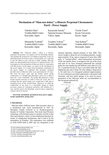
parts. A "celestial globe", which demonstrate movements<br />
<strong>of</strong> the sun and the moon, is arranged at the top <strong>of</strong> the clock<br />
and each <strong>of</strong> six faces arranged underneath the celestial<br />
globe has time displaying unit different each other [1], [2],<br />
[3]. A pedestal having six legs is provided under the time<br />
displaying unit and a chime for time telling is disposed in<br />
it. On each face <strong>of</strong> a hexagonal pedestal (approximately<br />
65 cm in diameter) provided underneath is decorated with<br />
cloisonne, and four spiral springs to be used for power<br />
generation <strong>of</strong> the Man-<strong>nen</strong> <strong>dokei</strong> are accommodated in<br />
this hexagonal pedestal [4].<br />
Keywords: mechanism, mechanical clock, power supply,<br />
torque equalization, spring, fusee<br />
I. Introduction<br />
Man-<strong>nen</strong> <strong>dokei</strong> (Official name: Man-<strong>nen</strong>-jimei shou) is<br />
a mechanical type clock manufactured in 1851 by<br />
Hisashige Tanaka (referred to as Karakuri-giemon),<br />
founder <strong>of</strong> Toshiba Corporation. This clock fused Western<br />
technology with Oriental nature to simulate real life at that<br />
time and realized a variety <strong>of</strong> time displaying functions by<br />
means <strong>of</strong> complicated mechanisms, and is said to be the<br />
masterpiece in Wa<strong>dokei</strong>. This masterpiece was exhibited<br />
at Aichi EXPO held in 2005 and was designated as the<br />
_______________________________________<br />
*E-mail: takehiro.hato@toshiba.co.jp<br />
†E-mail: k-suzuki@kahaku.go.jp<br />
‡E-mail: yoichi.tomii@viking.mbox.media.kyoto-u.ac.jp<br />
tE-mail: mitsunobu.yoshida@toshiba.co.jp<br />
**E-mail: yasuhiro.yokota@toshiba.co.jp<br />
††E-mail: yuji.kubota@toshiba.co.jp<br />
Fig. 1. Schema <strong>of</strong> power transmission
12th <strong>IFToMM</strong> World Congress, Besançon (France), June18-21, 2007<br />
Figure 1 shows a schema <strong>of</strong> power transmission from<br />
the spiral spring to the time display unit and the celestial<br />
globe. Two <strong>of</strong> four spiral springs compose one set <strong>of</strong><br />
power, and two sets <strong>of</strong> power are provided, one for time<br />
driving and the other is for chime striking. A power<br />
generated by the spiral spring is transmitted to the first<br />
wheel <strong>of</strong> time driving and <strong>of</strong> chime striking via fusees<br />
illustrated in conical form, and is then transmitted to each<br />
<strong>of</strong> driving parts to realize operations as the Man-<strong>nen</strong><br />
<strong>dokei</strong>.<br />
It is said that the Man-<strong>nen</strong> <strong>dokei</strong> functions continuously<br />
for one year if wound once. This description is seen in the<br />
advertisement and literature <strong>of</strong> the Man-<strong>nen</strong> <strong>dokei</strong> [5], [6].<br />
To realize this specification, composition <strong>of</strong> the power<br />
supply unit plays a vital role. A combination <strong>of</strong> spiral<br />
spring/fusee was invented in the 1500s, and used as power<br />
for clocks in France etc. and in 1600~1800 it was used for<br />
pocket watches [7]. In 1700s, chronometers were used for<br />
navigation <strong>of</strong> the sea, which resulted in development <strong>of</strong><br />
fusee mechanism technology. In view <strong>of</strong> the above, it is<br />
considered that around 1850 when the Man-<strong>nen</strong> <strong>dokei</strong> was<br />
manufactured, technology <strong>of</strong> spiral spring/fusee<br />
mechanism was promulgated to a certain extent in the<br />
West. Apparently, power generation mechanism by spiral<br />
spring/fusee was used in Yumihiki-doji and Shumisenngi,<br />
achievements by Hisashige Tanaka, which were produced<br />
prior to Man-<strong>nen</strong> <strong>dokei</strong> [8]. Although spiral spring/fusee<br />
composition was used in the Man-<strong>nen</strong> <strong>dokei</strong> as the power,<br />
it has two-spiral spring and two-fusee composition, which<br />
is not seen in Western mechanical type clocks and<br />
Hisashige's other workmanship, and this composition are<br />
considered extremely rare.<br />
As one <strong>of</strong> activities <strong>of</strong> national project " Inventions in<br />
the Edo period " promoted by the Ministry <strong>of</strong> Education,<br />
Culture, Sports, Science and Technology for the sake <strong>of</strong><br />
verification <strong>of</strong> technical level and creativity <strong>of</strong> Japan in<br />
Edo period, disassembly, investigation, restoration and<br />
duplication <strong>of</strong> the Man-<strong>nen</strong> <strong>dokei</strong> were carried out.<br />
Although disassembly survey was attempted so far several<br />
times [9], there is no data that deals with the details <strong>of</strong><br />
mechanisms and operations. For power supply unit which<br />
might have involved many originalities and ingenuities to<br />
realize operations for lengthy period <strong>of</strong> time, little record<br />
is left. Consequently we attempted to identify the structure<br />
<strong>of</strong> the power supply unit <strong>of</strong> the Man-<strong>nen</strong> <strong>dokei</strong> utilizing<br />
data acquired by the current disassembly survey and to<br />
investigate the mechanism. This paper reports the results<br />
we obtained.<br />
II. Composition <strong>of</strong> power supply unit<br />
A. Composition <strong>of</strong> mechanism<br />
Figure 2 shows CG perspective view and internal<br />
mechanism CG image <strong>of</strong> the power supply unit. In the<br />
wooden hexagonal pedestal, which is located at the<br />
bottom <strong>of</strong> the Man-<strong>nen</strong> <strong>dokei</strong>, four spiral springs being<br />
accommodated in a barrel drum are mounted. As shown in<br />
Fig. 2 (b), two barrel drums are connected by a chain and<br />
two spiral springs are composed to generate one power.<br />
As shown in the photograph <strong>of</strong> Fig. 3, it is designed so<br />
that shaft <strong>of</strong> one spiral spring per one power is fixed to the<br />
X-shaped metallic plate and shaft <strong>of</strong> other spiral spring is<br />
elongated to be connected as the output shaft to the fusee<br />
mechanism at upper part. None <strong>of</strong> barrel drum is fixed.<br />
With such a configuration, the sum <strong>of</strong> the number <strong>of</strong><br />
rotations <strong>of</strong> two springs is obtained by the output shaft.<br />
An output shaft <strong>of</strong> the spiral spring passes through legs<br />
<strong>of</strong> the six leg pedestal and conveys a power to the fusee<br />
mechanism shown in Fig. 4. A downward pointing fusee<br />
(input fusee) is directly mounted to the output shaft <strong>of</strong> the<br />
spiral, and is connected with an upward pointing fusee<br />
(output fusee) by a chain, and the power is then<br />
transmitted via output fusee gear to a first wheel that<br />
serves as the driving source <strong>of</strong> clock operations. In other<br />
words, outputs <strong>of</strong> two spiral springs are uniformed via two<br />
fusees and used for clock operations. When a spiral spring<br />
is once made free, it releases its power at once, so a speed<br />
regulating mechanism is required. For speed regulation <strong>of</strong><br />
time driving side, a speed regulator in the Western style<br />
clock plays this role. For speed regulation mechanism <strong>of</strong><br />
chime striking side, a whizzing wheel is provided that is<br />
turned intermittently and timing <strong>of</strong> this turning is<br />
interlocked with Wa<strong>dokei</strong> movement.<br />
The fusee has helix pr<strong>of</strong>ile as shown in Fig. 4 and this<br />
pr<strong>of</strong>ile determines how much the spiral springs output<br />
torque could be uniformed. Fusees used in the Man-<strong>nen</strong><br />
<strong>dokei</strong> are handmade and therefore, pr<strong>of</strong>iles <strong>of</strong> each fusee<br />
are delicately different. Table 1 shows dimensions<br />
(diameter) <strong>of</strong> each step in the cross section passing<br />
through the center <strong>of</strong> the fusee and the center <strong>of</strong> the hole<br />
<strong>of</strong> hooking the chain.<br />
(a) Perspective view<br />
(b) Internal mechanism<br />
Fig. 2. CG image <strong>of</strong> power supply unit<br />
Fig. 3. Spring section <strong>of</strong> the power supply unit
12th <strong>IFToMM</strong> World Congress, Besançon (France), June18-21, 2007<br />
The shaft <strong>of</strong> each fusee is supported by the elliptic<br />
shaped metallic plate(fusee support plate) and the pedestal<br />
frame. Further, as shown in Fig. 4, height <strong>of</strong> supporting at<br />
input fusee and at output fusee is shifted by thickness <strong>of</strong><br />
the gear <strong>of</strong> the output fusee. So the second ~ third step<br />
from the bottom <strong>of</strong> the input fusee and lowest step <strong>of</strong> the<br />
output fusee are connected by the chain. The fusee support<br />
plate is supported by four metal columns while two <strong>of</strong><br />
four metal columns are connected to the diagonal column<br />
support plate extending from the pedestal. This column<br />
support plate looks as if mounted to prevent turning <strong>of</strong> the<br />
fusee support plate. Besides, a comma-shaped cam<br />
configuration provided on the output fusee shaft forms a<br />
winding amount regulating mechanism with a lever shape<br />
part. The winding amount regulating mechanism is a<br />
mechanism for preventing excessive winding <strong>of</strong> the spiral<br />
spring and is normally used in spiral spring/fusee<br />
mechanism [7].The Man-<strong>nen</strong> <strong>dokei</strong> is designed in such<br />
that locking is applied when the output fusee is turned<br />
about six times. The output fusee makes one turn in 37.5<br />
days when calculated from rotational speed <strong>of</strong> the first<br />
wheel <strong>of</strong> the Western clock. It is noticed from this that the<br />
maximum continual movable days <strong>of</strong> the Man-<strong>nen</strong> <strong>dokei</strong><br />
is about 225 days from mechanism constitution. Although<br />
it was identified by the previous disassembly survey [9],<br />
the current study could confirm this together with reasons<br />
for that. Although this figure is less than the number <strong>of</strong><br />
days <strong>of</strong> yearly operation which has been believed till date,<br />
it is understood that a mechanism that realized an<br />
astonishing specification in those days was manufactured<br />
since number <strong>of</strong> days <strong>of</strong> clock operation at that time was<br />
about 10 days at the longest.<br />
Fig. 4. Fusee mechanism section <strong>of</strong> the power supply unit<br />
Fusee<br />
Fusee for<br />
driving clock<br />
Fusee for<br />
striking chime Average<br />
steps Input Output Input Output [mm]<br />
[mm] [mm] [mm] [mm]<br />
1 62.3 62.5 60.7 61.0 61.6<br />
2 61.6 52.7 57.0 57.0 57.1<br />
3 45.7 44.9 50.7 49.7 47.8<br />
4 39.1 38.5 44.2 43.4 41.3<br />
5 33.8 33.1 38.1 38.9 36.0<br />
6 29.5 29.3 31.9 31.5 30.6<br />
7 26.3 27.5 29.3 29.1 28.1<br />
8 23.7 25.7 26.9 26.5 25.7<br />
9 22.3 21.0 24.3 24.7 23.1<br />
Table 1. Fusee size data<br />
B. Forces exerted to wooden frame<br />
The column support plate shown in Fig. 4 is supposed to<br />
be a structure for preventing rotation <strong>of</strong> the fusee support<br />
plate from the assembled direction and configuration.<br />
Therefore this section reports results on how much power<br />
is exerted to the wooden frame (six leg pedestal)<br />
calculated from a geometrical relationship between the<br />
fusee support plate and the wooden frame.<br />
Figure 5 shows geometrical relationship between the<br />
fusee support plate and the wooden frame. In Fig. 5,<br />
length from point O to point A that is rotating center <strong>of</strong><br />
the input fusee is 88 [mm], length from point O to point B<br />
that is rotating center <strong>of</strong> the output fusee is 56 [mm],<br />
length from point O to x-compo<strong>nen</strong>t <strong>of</strong> point C (point C x )<br />
that is column support point <strong>of</strong> fusee support plate is 37<br />
[mm], and length from point O to y-compo<strong>nen</strong>t <strong>of</strong> point C<br />
(point C y ) is 54 [mm]. In this case, when considering the<br />
case where the symmetrical force interacts to Point O,<br />
force F A<br />
to turn the fusee support plate is expressed by<br />
x<br />
the following equation:<br />
OB<br />
FA x<br />
= FA<br />
= 0. 537FA<br />
AB<br />
A reaction force <strong>of</strong> this turning force is applied to the<br />
column support plate and force F applied to the wooden<br />
D<br />
frame is expressed as follows:<br />
OA<br />
F = D<br />
FA 0. 722F<br />
x<br />
A<br />
OC<br />
=<br />
Tensile force F D<br />
applied to the wooden frame and<br />
x<br />
shearing force F D<br />
which are desired to be obtained<br />
y<br />
finally are represented by the following equations:<br />
OC<br />
y<br />
FD = FD<br />
= 0. 596F<br />
(1)<br />
x A<br />
OC<br />
OCx<br />
FD = FD<br />
= 0. 408F<br />
(2)<br />
y A<br />
OC<br />
Next, force F applied to rotating center <strong>of</strong> the input<br />
A<br />
fusee is obtained from generated torque <strong>of</strong> the spiral<br />
spring. The fusee support plate, fusee and spiral spring are<br />
in a positional relationship shown in Fig. 6 and it is<br />
considered that force F′ generated by the spiral spring is<br />
A<br />
nearly equal to tensile force F exerted between fusees.<br />
A<br />
Torque T <strong>of</strong> the spiral spring is expressed as follows,<br />
z<br />
where Ω denotes maximum winding angle <strong>of</strong> spiral<br />
spring, α denotes released angle <strong>of</strong> spiral spring and M<br />
0<br />
denotes torque <strong>of</strong> spiral spring per unit angle.<br />
T Z<br />
= M<br />
0(<br />
Ω −α)<br />
(3)<br />
Then, force F′ can be obtained by the following<br />
A<br />
equation:<br />
TZ<br />
F ≅<br />
(4)<br />
′A<br />
R<br />
If initial state (α = 0) is considered where spiral spring is<br />
wound N times ( N denotes winding number <strong>of</strong> spiral
12th <strong>IFToMM</strong> World Congress, Besançon (France), June18-21, 2007<br />
spring), Eq. (4) can be rewritten as follows:<br />
2πM<br />
0<br />
F′ A<br />
≅ N<br />
(5)<br />
R<br />
N<br />
From measurement <strong>of</strong> torque <strong>of</strong> the spiral spring (see<br />
Section 3, Fig. 9),<br />
M<br />
0<br />
≅ 1450[kgfmm] = 14.2[Nm]<br />
and from measurement result R = 29.3 [mm] for spiral<br />
1<br />
spring wound once ( N = 1), force F′ is calculated as<br />
A<br />
follows:<br />
3<br />
F ≅ 311[kgf] = 3.05 10 [N]<br />
A , N = 1<br />
×<br />
Substituting this result into Eqs. (1) and (2), tensile force<br />
F D<br />
and shearing force F<br />
x<br />
D<br />
are obtained as follows:<br />
y<br />
3<br />
F ≅ 185 [kgf ] = 1.82 10 [N]<br />
F<br />
D<br />
×<br />
x<br />
D<br />
≅ 127[kgf] = 1.24×<br />
y<br />
10<br />
3<br />
[N]<br />
As shown above, a sizable force is exerted to the wooden<br />
frame even if the spiral spring is wound only once.<br />
Although strength <strong>of</strong> the wooden frame is unknown,<br />
cracks are observed with the wooden frame in fact. From<br />
this, it is considered that in practice, spiral spring could<br />
not be turned that much.<br />
III. Spiral springs<br />
A. Pr<strong>of</strong>ile and materials<br />
It is considered that spiral springs mounted currently to<br />
the Man-<strong>nen</strong> <strong>dokei</strong> are the third generation. The first<br />
generation spiral spring was forged by a sword-smith<br />
upon request by Hisashige Tanaka and the second<br />
generation spiral spring is the replacement replaced in<br />
1884 when the Man-<strong>nen</strong> <strong>dokei</strong> was disassembled by<br />
S.Tanaka (disciple <strong>of</strong> 1st Hisashige Tanaka) upon request<br />
by 2nd Hisashige Tanaka. At this time, since the cracks<br />
were found with the spiral spring, it was replaced. The<br />
third generation spiral spring was replaced at disassembly<br />
survey <strong>of</strong> the Man-<strong>nen</strong> <strong>dokei</strong> carried out in 1949 by T.<br />
Asahina et al. at National Science Museum. Also at this<br />
survey, spiral springs were found cracked and those <strong>of</strong> the<br />
same quality were produced and used for replacement.<br />
Since there is no description <strong>of</strong> spiral spring replacement<br />
other than the said replacement made twice [10], it is<br />
considered that the third generation spiral spring is<br />
mounted to the Man-<strong>nen</strong> <strong>dokei</strong>. Figure 7 is a photograph<br />
showing the third generation spiral spring.<br />
The current survey includes dimensional measurements<br />
and analysis <strong>of</strong> materials <strong>of</strong> the third generation spiral<br />
spring. Table 2 shows results obtained. Further, from<br />
dimensions <strong>of</strong> the spiral spring shown in Table 2, effective<br />
number <strong>of</strong> rotations <strong>of</strong> the spiral spring is calculated to be<br />
about 3.8 turns.<br />
Fig. 5. Geometrical configuration <strong>of</strong> fusee support plate and wooden<br />
frame<br />
Fig. 7. Spiral spring (third generation)<br />
Fig. 8. Torque measuring apparatus<br />
(a) Side view<br />
(b) Top view <strong>of</strong> fusee<br />
Fig. 6. Cross section diagram <strong>of</strong> power supply unit<br />
Length<br />
3050 [mm]<br />
Width<br />
65 [mm]<br />
Spring Thickness<br />
1.9 [mm]<br />
Material<br />
7-3 BrassCu:73.08%, Zn:26.20%,<br />
Sn:0.35%, Pb:0.15%, Fe:0.22%<br />
Barrel Diameter<br />
φ120.5 [mm]<br />
Shaft Diameter<br />
φ 27.0 [mm]<br />
Table 2. Size and material analysis <strong>of</strong> the spring
12th <strong>IFToMM</strong> World Congress, Besançon (France), June18-21, 2007<br />
Fig. 10. Fusee and spring barrel composition<br />
Fig. 9. Experimental result <strong>of</strong> spring torque<br />
B. Torque characteristics<br />
Next, measurement <strong>of</strong> torque <strong>of</strong> the third generation<br />
spiral spring will be discussed. As shown in Fig. 8, the<br />
barrel drum <strong>of</strong> the spiral spring was fixed, the spiral<br />
spring was turned gradually from released state, and<br />
torque at each number <strong>of</strong> rotations was measured. Results<br />
<strong>of</strong> the measurement <strong>of</strong> torque are shown in Fig. 9.<br />
Although outside <strong>of</strong> the barrel drum was reinforced before<br />
current measurements, experiments were limited to 1.5<br />
turns in fear <strong>of</strong> possible deformations <strong>of</strong> the barrel drum<br />
having thickness <strong>of</strong> only 1 mm. Therefore, torque for<br />
more than 1.5 turns is <strong>of</strong> estimated value. Since effective<br />
number <strong>of</strong> turns <strong>of</strong> the third generation spiral spring is<br />
about 3.8 turns as mentioned previously, results in Fig. 9<br />
are for torque values up to 3.8 turns.<br />
IV. Fusee mechanism<br />
Torque generated by a spiral spring varies greatly when<br />
released from wound state. Fusee was devised to make<br />
these variations uniform. Normally, the fusee mechanism<br />
is composed <strong>of</strong> combination <strong>of</strong> a fusee having sectional<br />
pr<strong>of</strong>ile close to parabola and a cylinder (in many cases,<br />
barrel drum storing spiral springs) (Fig. 10) [7]. However,<br />
in the case <strong>of</strong> the Man-<strong>nen</strong> <strong>dokei</strong>, two fusees are arranged<br />
in upward and downward directions as shown in Fig. 4. In<br />
this chapter, power characteristics <strong>of</strong> the Man-<strong>nen</strong> <strong>dokei</strong><br />
using two fusees are assumed and reasons for that two<br />
fusees are employed are discussed.<br />
A. Characteristics <strong>of</strong> Man-<strong>nen</strong> <strong>dokei</strong> power supply unit<br />
A case where a fusee is provided to spiral spring side<br />
too as shown in Fig.11 is considered. Suppose that a chain<br />
is applied to radius R (α ) position <strong>of</strong> the input fusee<br />
(which is connected to spiral spring) and at radius r (β )<br />
position <strong>of</strong> the output fusee. Torque <strong>of</strong> the spiral spring<br />
can be expressed by Eq. (3) and torque T conveyed to<br />
out<br />
the output shaft is then expressed as:<br />
r<br />
T out = M 0 ( Ω −α)<br />
(6)<br />
R<br />
Fig. 11. Fusee composition <strong>of</strong> Man-<strong>nen</strong> <strong>dokei</strong><br />
If the chain is released from input fusee by a small mount<br />
<strong>of</strong> R ⋅ dα<br />
, the same length r ⋅ dβ<br />
should be wound at<br />
output fusee, then the following equation is established:<br />
∫ α<br />
R ( α)<br />
dα<br />
= ∫<br />
β<br />
r(<br />
β ) dβ<br />
(7)<br />
0<br />
0<br />
If maximum number <strong>of</strong> rotations <strong>of</strong> the spiral spring is<br />
represented by N , number <strong>of</strong> turns <strong>of</strong> the spiral spring<br />
from the place it is winded to the maximum extent is<br />
represented by n , and number <strong>of</strong> rotations <strong>of</strong> the output<br />
shaft is by m , the following relationships are obtained:<br />
Ω = 2 πN<br />
, α = 2πn,<br />
β = 2πm<br />
(8)<br />
Using Eqs. (8) in Eqs. (6) and (7), the following<br />
relationships are obtained:<br />
r(<br />
m)<br />
T out = 2π M 0 ( N − n)<br />
(9)<br />
R(<br />
n)<br />
∫ n<br />
R n)<br />
dn = ∫<br />
m<br />
0<br />
( r(<br />
m)<br />
dm<br />
(10)<br />
0<br />
To obtain torque characteristics <strong>of</strong> the output shaft, Eq. (9)<br />
is simply calculated under the condition that R (n)<br />
and<br />
r (m) satisfy the relationship expressed by Eq. (10).<br />
Using formula processing s<strong>of</strong>tware Mathematica<br />
(registered trademark <strong>of</strong> Wolfram Research, Inc.),<br />
characteristics <strong>of</strong> the output shaft were calculated by Eqs.<br />
(9) and (10). Pr<strong>of</strong>ile R (n)<br />
and r (m)<br />
<strong>of</strong> the fusee were<br />
obtained by supplementing actual measurements shown in<br />
Table 2 by tertiary polynomial expression. Calculations<br />
were made for two cases, one is a case spiral spring shaft<br />
is turned eight times to allow continuous operation <strong>of</strong> one<br />
year and the other is a case <strong>of</strong> five turns that is close to the<br />
composition remained at present. Results are shown in Fig.<br />
12 by solid line and dotted lines.<br />
B. Discussions <strong>of</strong> use <strong>of</strong> two fusees<br />
In this section, discussion is made on why Hisashige<br />
Tanaka used two fusees in the Man-<strong>nen</strong> <strong>dokei</strong>. First, with<br />
a combination <strong>of</strong> cylinder and fusee which is an ordinary<br />
composition <strong>of</strong> the fusee mechanism, virtual design was
12th <strong>IFToMM</strong> World Congress, Besançon (France), June18-21, 2007<br />
fusee that is ordinary composition <strong>of</strong> the fusee mechanism,<br />
unnecessarily large power is not exerted to the wooden<br />
frame and uniform output is obtained, and this<br />
configuration is thus suited for the power supply system<br />
<strong>of</strong> the Man-<strong>nen</strong> <strong>dokei</strong>. The reason why Hisashige Tanaka<br />
used two-fusee composition remains still to be unclear.<br />
Fig. 12. Calculated results <strong>of</strong> spring output torque<br />
attempted to know what output characteristics would be<br />
obtained. As the design constraint condition, that the fusee<br />
mechanism should be accommodated within the wooden<br />
frame (six leg pedestal) was used. Specifically, the<br />
following equation<br />
R + r 70 [mm]<br />
0 8<br />
≤<br />
was used as the constraint condition where radius <strong>of</strong> the<br />
cylinder is represented by R and maximum radius <strong>of</strong> the<br />
0<br />
fusee is represented by r 8<br />
.<br />
Radius <strong>of</strong> the fusee that maintains output torque<br />
constant is obtained by the following equation [7]:<br />
r0<br />
r m = (11)<br />
2r0<br />
m<br />
1−<br />
R0<br />
N<br />
where, r is 12.3 [mm] same as that <strong>of</strong> actual fusee.<br />
0<br />
Further, maximum level <strong>of</strong> number <strong>of</strong> rotations m <strong>of</strong> the<br />
output shaft is assumed to be m = 8 supposing<br />
max<br />
continuous operation <strong>of</strong> one year.<br />
In promoting virtual design, it is considered that number<br />
<strong>of</strong> rotations <strong>of</strong> the spiral spring shaft N be kept minimal<br />
as much as possible so that large power may not act on the<br />
wooden frame. However, if N is made smaller, R in the<br />
0<br />
denominator <strong>of</strong> right side member <strong>of</strong> Eq. (11) should be<br />
made larger, which does not meet with the constraint<br />
condition. So in this discussion, virtual design is promoted<br />
using N = 6. If it is assumed that the spring is fully<br />
released when the output shaft rotates eight times,<br />
R = 32.8 [mm]<br />
0<br />
is obtained from the condition that the denominator <strong>of</strong><br />
right side member <strong>of</strong> Eq. (11) is zero. Accordingly, it is<br />
now possible to increase r up to 37.2 [mm] from the<br />
8<br />
constraint condition.<br />
From Eq. (11), r k<br />
(k=1,2,.... ,7) are obtained as follows:<br />
r 1 =13.1, r 2 =14.2, r 3 =15.6, r 4 =17.4, r 5 =20.1,<br />
r 6 =24.6, r 7 =34.8 (all units are [mm])<br />
Pr<strong>of</strong>iles <strong>of</strong> the fusee were supplemented by the tertiary<br />
polynomial expression and torque characteristics <strong>of</strong> the<br />
output shaft were calculated as shown in Fig. 12 by<br />
dashed-dotted line. It is noticed from Fig. 12 that with one<br />
V. Conclusion<br />
This paper deals with clarification <strong>of</strong> mechanism <strong>of</strong> the<br />
power supply unit <strong>of</strong> the Man-<strong>nen</strong> <strong>dokei</strong> and discussions<br />
involved. It has been found that from composition <strong>of</strong> the<br />
mechanism <strong>of</strong> the power supply unit, the maximum<br />
continual movable days <strong>of</strong> the Man-<strong>nen</strong> <strong>dokei</strong> now<br />
existing is to be about 225 days, and it is considered that<br />
from the number <strong>of</strong> steps <strong>of</strong> fusees and devisal for<br />
lengthening driving hours by double configuration spiral<br />
springs, Hisashige Tanaka would have targeted<br />
continuous operation for one year. Although spiral springs<br />
generating a huge torque were necessary to realize a<br />
power supply unit capable <strong>of</strong> allowing continuous one<br />
year operation, it is assumed that the spiral spring were<br />
wound just a little due to strength poverty <strong>of</strong> the wooden<br />
frame. In order to attain the torque required for one-year<br />
continuous operation in stable fashion, one-fusee<br />
composition allows reasonable design and hence, the<br />
reason why Hisashige Tanaka used two-fusee composition<br />
remains still to be unclear.<br />
Acknowledgement<br />
We wish to express our heartiest thanks to Seiko<br />
Precision Inc. and Sunco Spring Co., Ltd, for their great<br />
cooperation in promoting this study.<br />
References<br />
[1] Y. Kubota. <strong>Mechanism</strong> <strong>of</strong> "Man-<strong>nen</strong> <strong>dokei</strong>." In Toshiba Review,<br />
Vol. 6, No. 7, pages 116-119, 2005.<br />
[2] M. Yoshida et al. <strong>Mechanism</strong> <strong>of</strong> the Man-<strong>nen</strong> <strong>dokei</strong> Part 1:<br />
Wa<strong>dokei</strong>. In Proceedings <strong>of</strong> JSME Mechanical Engineering<br />
Congress, Vol. 5, pages 51-52, Japan, September 19-22, 2005.<br />
[3] Y. Yokota et al. <strong>Mechanism</strong> <strong>of</strong> the Man-<strong>nen</strong> <strong>dokei</strong> Part 2: Celestial<br />
globe. In Proceedings <strong>of</strong> JSME Mechanical Engineering Congress,<br />
Vol. 5, pages 53-54, Japan, September 19-22, 2005<br />
[4] T. Hato et al. <strong>Mechanism</strong> <strong>of</strong> the Man-<strong>nen</strong> <strong>dokei</strong> Part 3: Power<br />
supply. In Proceedings <strong>of</strong> JSME Mechanical Engineering Congress,<br />
Vol. 5, pages 55-56, Japan, September 19-22, 2005<br />
[5] H. Tanaka. Man-<strong>nen</strong> <strong>dokei</strong> design drawings. owned by National<br />
Science Museum.<br />
[6] 3rd Hisashige Tanaka. Configuration <strong>of</strong> the Man-<strong>nen</strong> <strong>dokei</strong>. 1957.<br />
[7] T. Aoki. Horology. Maruzen Co., 1938.<br />
[8] K. Suzuki. "<strong>Mechanism</strong> Arts" ~Japanese Automata "KARAKURI."<br />
In Journal <strong>of</strong> Japan Society for Design Engineering, Vol.31, No.2,<br />
pages 41-47, 1996.<br />
[9] T. Asahina and S. Oda. "Myriad-Year Clock" Made by G. H.<br />
Tanaka 100 Years Ago in Japan. In Bulletin <strong>of</strong> the National Science<br />
Museum (Tokyo) Vol.1No.2, September 1954.<br />
[10] 3rd Hisashige Tanaka. History <strong>of</strong> the Man-<strong>nen</strong> <strong>dokei</strong>. 1960.