You also want an ePaper? Increase the reach of your titles
YUMPU automatically turns print PDFs into web optimized ePapers that Google loves.
Optica Applicata, Vol. XXXV, No. 2, 2005<br />
Physical analysis of an operation of GaInAs/GaAs<br />
quantum-well vertical-cavity surface-emitting<br />
diode lasers emitting in the 1.3-µm wavelength range<br />
ROBERT P. SARZAŁA<br />
Laboratory of Computer Physics, Institute of Physics, Technical University of Łódź,<br />
ul. Wólczańska 219, 93-005 Łódź, Poland; e-mail: rpsarzal@p.lodz.pl<br />
Comprehensive three-dimensional self-consistent optical-electrical-thermal-gain physical modelling<br />
is used to simulate room-temperature continuous-wave performance characteristics of GaInAs/GaAs<br />
lasers emitting in the 1.3-µm wavelength range. The simulation takes into consideration all physical<br />
phenomena crucial for a laser operation including all important interactions between them. A real<br />
possibility to design high-performance 1.26-µm GaInAs/GaAs quantum-well vertical-cavity<br />
surface-emitting diode lasers (VCSELs) with the aid of a currently available technology is shown.<br />
Their outputs are much higher than in the case of their quantum-dot version. Methods to shift the<br />
emitting wavelength range of 1.3 µm are discussed and anticipated performance characteristics of<br />
such a 1.3-µm VCSELs are determined.<br />
Keywords: semiconductor laser, VCSEL, GaInAs/GaAs QW.<br />
1. Introduction<br />
Telecommunication systems at the optical fiber window of 1.3 µm exhibit many<br />
advantages over their earlier 0.85 µm counterparts [1]. In the modern short- and<br />
medium-distance optical fibre links (< 50 km), the cost of transmitter devices represents<br />
quite a significant fraction of the total system cost. Vertical-cavity surface-emitting<br />
laser (VCSEL) structure is believed to be the most suited laser configuration for optical<br />
transmitters. It follows from its inherently single-longitudinal-mode operation, easy<br />
fibre coupling, facility in modulation and straightforward fabrication of two-dimensional<br />
arrays. Currently commercially available long-wavelength 1.3-µm diode lasers are<br />
based on (InGa)(AsP)/InP structures, often with GaAs/AlAs distributed Bragg<br />
reflector (DBR) mirrors. This solution requires a complicated growth and processing<br />
procedure which is probably too expensive for mass-produced commercial devices.<br />
Besides, since the above lasers exhibit poor temperature characteristics mainly due to<br />
insufficient electron confinement, thermoelectric coolers are required in their practical
226 R.P. SARZAŁA<br />
use. Therefore, taking additionally into consideration the well established arsenide<br />
technology (GaAs/(AlGa)As/AlAs structures with GaAs/AlAs DBRs and oxidized<br />
AlAs layers), currently the most promising solution to this problem seems to be<br />
arsenide structures with such active-gain materials which are lattice matched to GaAs<br />
and emit in the 1.3 µm range. Then the whole structure could be grown in one epitaxial<br />
process which considerably reduces its costs and enables the mass manufacturing.<br />
One of possible and, at the same time, natural ways to solve the above problem is<br />
to modify the GaAs/(AlGa)As/AlAs devices by adding the GaInAs/GaAs structures.<br />
Traditionally this system was used to manufacture devices emitting radiation of<br />
wavelengths up to 1 µm [2], recently, however, development of MBE and MOCVD<br />
technologies has enabled manufacturing devices which emit radiation of longer<br />
wavelengths. Currently GaInAs/GaAs quantum-well (QW) structures [3, 4] and based<br />
on them edge-emitting diode lasers [5, 6] emitting radiation of wavelengths even<br />
exceeding 1.2 µm are produced. To achieve such long wavelengths, InAs mole fraction<br />
should be increased to at least 40%. It is followed by a large lattice misfit reaching<br />
even +2.9% leading to considerable stresses. Efficient photoluminescence is in such<br />
structures rather difficult to achieve and needs improving the technology.<br />
The above structures were also used to design vertical-cavity surface-emitting<br />
diode lasers (VCSELs) emitting radiation of wavelengths exceeding 1.26 µm [7, 8].<br />
It requires waveguides of detuned spectral characteristics towards higher wavelengths<br />
with respect to the maximal-gain wavelength. It is expected that such VCSELs will be<br />
manufactured, emitting radiation of over 1 mW power and with still relatively low<br />
threshold current of the order of some milliamperes. Such lasing devices may be used<br />
as sources of a carrier wave in 10 Gbps single-mode Ethernet [9] or SONET OC-192<br />
[10] networks.<br />
2. Structure<br />
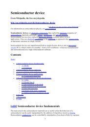
The device under consideration (Fig. 1) is a typical double-intracavity-contact VCSEL<br />
structure. It consists of two 8-nm GaInAs/GaAs QWs (double QW (DQW) structure),<br />
each containing about 40% indium, separated by the 25-nm GaAs barrier, both<br />
intentionally undoped (residual 10 16 cm –3 doping is assumed). The above QW<br />
structures, especially their compositions and layer thickness, are probably limiting the<br />
possible achievements of current manufacturing technologies. The active region is<br />
sandwiched by the p-type and the n-type GaAs spacers. The upper part (over the oxide<br />
aperture) of the p-type spacer is doped to 2×10 18 cm –3 , whereas the lower one (between<br />
the oxide and the active region) is doped only to 10 17 cm –3 . Analogously, the upper<br />
part (between the active region and the base of the mesa structure) of the n-type<br />
spacer is doped to only 10 16 cm –3 , whereas the bottom one – to 10 18 cm –3 . Relatively<br />
high doping of the upper part of the p-type spacer and the bottom part of the n-type<br />
one is applied to reduce their electrical resistivities because they are also working as<br />
radial-current-spreading layers for a current flow from annular contacts towards the<br />
central active region. 28 periods of quarter-wave GaAs/Al 0.8 Ga 0.2 As layers (of total
Physical analysis of an operation of GaInAs/GaAs... 227<br />
Fig. 1. Typical structure of the 1.3-µm GaAs-based oxide-confined (OC) GaInAs/GaAs double<br />
quantum-well (DQW) vertical-cavity surface-emitting laser (VCSEL).<br />
reflectivity of 99.9350%) and analogous 34 periods of GaAs/AlAs layers (99.9943%)<br />
are assumed as upper and bottom, respectively, DBR resonator mirrors. Their<br />
diameters are equal to 50 and 100 µm, respectively. Two (n- and p-side) annular<br />
contacts are deposited on both GaAs spacer layers (see Fig. 1). Internal contact<br />
diameters are postulated to be equal to 54 µm (p-side) and 74 µm (n-side), respectively,<br />
whereas external ones – to 70 and 100 µm. Typical values of their contact resistances<br />
are equal to 10 –5 Ωcm 2 (n-side) and 10 –4 Ωcm 2 (p-side) (reported values, see, e.g.,<br />
[11, 12], are even much lower).<br />
A radial selective oxidation (transforming AlAs into Al x O y native oxides) is<br />
proposed to create within the p-type GaAs spacer the oxide aperture working as both<br />
T a b l e 1. Compositions and thicknesses (in nm) of structure layers of the 3λ/2-cavity VCSEL. Some<br />
values of model parameters are also given.<br />
Wavelength 1200 nm 1250 nm 1300 nm<br />
Layer<br />
Upper DBR<br />
GaAs 87.4 91.3 95.3<br />
Al 0.8 Ga 0.2 As 98.7 103.0 107.3<br />
p-GaAs 168.2 176.2 184.1<br />
p-Al 0.98 Ga 0.02 As/Al x O y 15 15 15<br />
GaAs 149.6 157.6 165.4<br />
QW-GaInAs 8 8 8<br />
Active region B-GaAs 20 20 20<br />
QW-GaInAs 8 8 8<br />
GaAs 76.1 84.0 91.9<br />
n-GaAs 80 80 80<br />
Bottom DBR<br />
AlAs 102.2 106.7 111.1<br />
GaAs 87.4 91.3 95.3
228 R.P. SARZAŁA<br />
the electrical (to funnel current spreading from annular contact towards the central<br />
active region) and the optical (to confine an optical field in a radial direction) apertures<br />
of an assumed diameter of φ =2r A . A nominal thickness of oxide apertures is assumed<br />
to be equal to 15 nm. For all the designs, an optimal value φ =4µm was assumed.<br />
In order to reduce the threshold current, which has happened to be very important<br />
for designing 1.3-µm GaInAs/GaAs VCSELs, a short resonator, namely the 1.5λ cavity<br />
is considered. Both the active region and the oxide aperture are assumed to be located<br />
exactly in the anti-node positions of the optical standing wave.<br />
Compositions and thicknesses of structure layers are listed in Tab. 1 for three<br />
resonator configurations tuned, respectively, to emission of 1200, 1250 and 1300-nm<br />
radiation. For all three cases, the active region remains the same. Expected wavelengths<br />
of radiation were compelled by a suitable cavity and DBR configurations assuming<br />
high enough optical gain from tail parts of material gain spectra.<br />
3. Model<br />
The model is composed of five interrelated parts. In successive subsections, the band<br />
structure of the GaInAs/GaAs quantum well as well as electrical, optical, thermal and<br />
gain processes crucial for the laser operation are described, followed by an explanation<br />
of all essential interactions between various physical phenomena. General rules of<br />
the advanced modeling of a VCSEL operation are formulated by OSIŃSKI and<br />
NAKWASKI [13].<br />
3.1. GaInAs/GaAs quantum well<br />
Determination of a quantum-well band structure and its energy levels needs<br />
knowledge of values of the band-gaps, the effective masses and the band offset. The<br />
room-temperature (RT) value of the band-gap of the Ga 1–x In x As material is taken from<br />
[14] in the following form:<br />
E GaInAs (x, 0K) = 1.512 – 1.337x + 0.27x 2 [eV]. (1)<br />
The band-gap for GaAs at 0K is found from [15]: E GaAs (0K) = 1.519 eV. For other<br />
temperatures, the band-gaps are determined from the Varshni relation:<br />
α E<br />
T 2<br />
ET ( ) = E( 0K)<br />
– -------------------<br />
+ T<br />
β E<br />
(2)<br />
where values of α E and β E parameters are listed in Tab. 2.<br />
On the basis of data reported in [16], the band offset ratio is assumed for the<br />
GaInAs/GaAs material to be equal to 0.70/0.20. The matrix element is found theoretically<br />
from Eq. (2). The electron effective mass m e<br />
*<br />
= [0.026 + 0.041(1 – x)]m 0
Physical analysis of an operation of GaInAs/GaAs... 229<br />
Table 2. The α E and β E parameters used in Eq. (2).<br />
Material α E [10 –4 eV/K] β E [K]<br />
GaAs [30] 5.405 204<br />
GaInAs [14] 5.408 204<br />
is taken from [17], and those for the heavy hole = (0.445 – 0.035x)m 0 and the<br />
*<br />
light hole = 0.156m 0 – from [18] and [19], respectively.<br />
m lh<br />
3.2. Electrical model<br />
Current spreading in a laser volume is determined from three-dimensional potential<br />
distributions V(r, z, ϕ) found by solving, with the aid of the finite-element (FE)<br />
method, the Laplace equation<br />
*<br />
m hh<br />
div σ ( r, z,<br />
ϕ)grad⎛V( r, z,<br />
ϕ)<br />
⎞ = 0<br />
⎝ ⎠<br />
(3)<br />
where σ stands for the 3D profile of electrical conductivity and r, z and ϕ compose<br />
the cylindrical co-ordinate system with 0z axis directed along the device axis. For all<br />
layers of the laser structure (with the exception of the active region), the above<br />
conductivity σ depends on material composition and its doping, as well as on a local<br />
temperature and a local carrier concentration [20]. Generation and recombination<br />
phenomena within the active region are usually a source of the non-zero right-hand<br />
side of Eq. (3) (known as the Poisson equation in this case). Their relative influence<br />
is difficult to analyze theoretically, therefore they have been taken symbolically into<br />
account in the model with the aid of the effective conductivity σ pn of the active-region<br />
material. Its value is found using the differential Ohm’s law and the classical diode<br />
equation:<br />
σ pn<br />
( r)<br />
=<br />
β pn<br />
j pn<br />
( r)d ------------------------------------------- A,<br />
E<br />
j pn<br />
( r)<br />
ln ------------------ + 1<br />
j s<br />
(4)<br />
where j pn is the p-n junction current density and d A, E = 25 nm (GaAs) +<br />
+ 2×8 nm (GaInAs) = 41 nm (see Tab. 1) stands for the cumulative active-region<br />
thickness including not only QW layers but also barrier layers between them;<br />
β pn = 19 V –1 is the diode parameter and j s = 1.1 A/m 2 stands for the saturation current<br />
density.<br />
To obtain 3D potential profile for the whole laser structure, it should be matched<br />
(using the self-consistent approach) with the aid of boundary conditions at all
230 R.P. SARZAŁA<br />
boundaries between the layers. Then the 3D current density distribution j(r, z, ϕ) may<br />
be found within the whole device volume from the differential Ohm law:<br />
jrzϕ ( , , ) = – σ ( r, z,<br />
ϕ)<br />
grad V( r, z,<br />
ϕ) .<br />
(5)<br />
Afterwards, carrier density profile n A (r) within the active layer may be determined<br />
from the below-threshold diffusion equation:<br />
D A<br />
∂ 2 n A ( r)<br />
--------------------- ---- 1 ∂nA( r)<br />
2 3 j<br />
-------------------<br />
pn ( r)<br />
+ – An<br />
∂r 2 r ∂r<br />
A<br />
( r)<br />
– Bn A( r)<br />
– CnA( r)<br />
+ ------------------ = 0<br />
ed A<br />
(6)<br />
where D A =10cm 2 /s is the ambipolar diffusion coefficient [21] and the recombination<br />
coefficients for temperatures within the range are extracted from the data reported in<br />
[22] in the following forms:<br />
A = (138.06 – 0.109T )10 7 [s –1 ], (7a)<br />
B = (25.35 – 0.0562T )10 –11 [cm 3 s –1 ], (7b)<br />
C = (–6.22 + 0.0344T )10 –29 [cm 6 s –1 ]. (7c)<br />
Values of the above recombination coefficients are taken from the GaInNAs<br />
measurements of a similar In content because analogous values for GaInAs have not<br />
been reported yet. A relatively high value of the A coefficient is in GaInNAs associated<br />
with a high density of nonradiative recombination centers. Expected high densities of<br />
analogous centers in GaInAs will be probably followed by a similar high value of its<br />
coefficient. Values of both remaining coefficients are not essentially different from<br />
their standard values reported for similar materials.<br />
3.3. Optical model<br />
The optical model is based on the effective frequency method (EFM) [23]. The<br />
structure eigenmode is assumed to be of the following form:<br />
Erzϕ ( , , , t) = Erzϕ ( , , ) exp( iωt)<br />
(8)<br />
with a complex mode frequency<br />
ω = ω' + iω''<br />
(9)<br />
accounting for possible loss and gain effects within the optical cavity.<br />
Assuming circular symmetry of a VCSEL geometry, the optical field may be<br />
separated into two approximating one-dimensional functions<br />
Erzϕ ( , , ) = f( r,<br />
z)Φ L<br />
( r) exp( iLϕ),<br />
L = 0, 1, 2, … (10)
Physical analysis of an operation of GaInAs/GaAs... 231<br />
where L is the azimuthal mode number. The axial part of the solution is assumed to be<br />
normalized<br />
L L ( r)<br />
∫<br />
f 2 ( r,<br />
z )dz = 1<br />
0<br />
where L L (r) corresponds to the resonator length at the radius r. Finally, complex optical<br />
fields in VCSEL resonators are simplified to be governed by two mutually interrelated<br />
nearly-one-dimensional wave equations along both axial and radial directions:<br />
(11)<br />
d 2<br />
2 2 2<br />
---------- + k<br />
dz 2 0 nR( r,<br />
z)<br />
f( r,<br />
z)<br />
= νeff ( r)k 0 nR ( r,<br />
z)n g<br />
( r,<br />
z) f( r,<br />
z)<br />
,<br />
1<br />
---------- --- d 2 2<br />
+ ------- – -------- + ν<br />
dr 2 r dr r 2 eff<br />
( r)k 0<br />
〈 nR n g<br />
〉 r<br />
Φ L<br />
( r) = ν k 0<br />
〈 nR n g<br />
〉 r<br />
Φ L<br />
( r)<br />
d 2<br />
L 2<br />
(12)<br />
(13)<br />
where ν eff is the effective frequency, k 0 = ω 0 /c is the vacuum wave number, and ω 0 is<br />
the real-valued nominal angular frequency corresponding to the designed periodicity<br />
of DBR mirrors; n R (r, z, ϕ, ω 0 ) and n g (r, z, ϕ, ω 0 ) are the complex refractive phase and<br />
group indices, respectively, evaluated at the nominal angular frequency ω 0 . The<br />
dimensionless complex parameter ν plays a role of an eigenvalue and is defined as<br />
ν 2 ω 0 – ω<br />
≡ ------------------- 2 λ – λ 0<br />
= ----------------- – i -------------.<br />
2ω''<br />
λ<br />
ω 0<br />
ω 0<br />
(14)<br />
Its real part describes the relative wavelength shift from the nominal wavelength λ 0 ,<br />
whereas its imaginary part is the relative decay constant of the corresponding mode.<br />
〈 n R n g 〉 r<br />
may be written in the following form:<br />
L L ( r)<br />
∫<br />
〈 n R<br />
n g<br />
〉 r<br />
= n R<br />
( r,<br />
z)n g<br />
( r,<br />
z)f 2 ( r,<br />
z)dz.<br />
0<br />
(15)<br />
Assuming the outgoing plane waves at the bottom (z = 0) and the top (z = L L )<br />
surfaces of the laser cavity, the following axial boundary conditions may be formulated<br />
d f<br />
--------- ± ik<br />
dz z<br />
f = 0, z<br />
⎧L L<br />
( r) + ε ⎫<br />
= ⎨ ⎬<br />
⎩0 – ε ⎭<br />
where ε is a small positive number and k z = k 0 (n R 2 – ν eff n R n g ). So, the structure is<br />
divided into a number of cylindrically symmetric ring sectors. Constant and uniform<br />
distributions of refractive indices and of loss and gain coefficients within every<br />
(16)
232 R.P. SARZAŁA<br />
individual layer and every individual sector are assumed – but they may be different<br />
in different layers and in different sectors.<br />
Analogously, Φ L (r) (L = 0,1, 2, ...) are assumed to satisfy the following boundary<br />
conditions, ensuring a cylindrical outgoing wave at sufficiently large radial distance r ∞<br />
dΦ L<br />
( r)<br />
Φ<br />
-------------------- L<br />
( r)<br />
+ ----------------- + ik (r = r ∞ ) (17)<br />
dr 2r r<br />
Φ L<br />
( r)<br />
= 0<br />
1 ⁄ 2<br />
where k r<br />
= k 0<br />
( ν eff<br />
– ν) 〈 n R<br />
n g<br />
〉 r<br />
. The radial field is determined for a structure<br />
averaged in the z-direction, as if the waveguide were uniform, although slow radial<br />
changes of losses (or gains) and refractive indices are also included.<br />
The algorithm needs self-consistent procedure because the effective frequency ν eff<br />
is present in both nearly one-dimensional wave Eqs. (12) and (13).<br />
3.4. Thermal model<br />
The FE thermal model of the laser solves the heat-conduction equation for the whole<br />
structure using the same mesh generated for the FE electrical calculations<br />
div λ T<br />
( r, z,<br />
ϕ)grad⎛T( r, z,<br />
ϕ)<br />
⎞ = – g<br />
⎝ ⎠ T<br />
( r, z,<br />
ϕ).<br />
(18)<br />
In the above equation, λ T stands for the thermal conductivity coefficient (Wm –1 K –1 )<br />
and g T is the volume density of heat sources (Wm –3 ). Thermal conductivity of the<br />
oxidized Al x O y layer is assumed equal to that of the sapphire (Al 2 O 3 ) – 19.65 W/mK<br />
[24] and that of semiconductor layers are taken from [25]. Nonradiative recombination<br />
and reabsorption of spontaneous radiation are found to be main heat sources located<br />
within the active region of the laser. Additionally, the volume Joule heating in all<br />
structure layers and the barrier Joule heating in the contacts are taken into account.<br />
3D heat-flux spreading in a copper heat sink is determined assuming its external walls<br />
to be kept at the RT of the ambient. Side and top laser-crystal walls are assumed to be<br />
thermally isolated because an influence of both thermal radiation and thermal<br />
convection of air particles is negligible as compared with intense heat-flux conduction<br />
through the bottom device base into its heat sink.<br />
3.5. Gain model<br />
In the calculation of the optical gain, the classical Fermi’s Golden Rule and the<br />
parabolic band-gap approximation are assumed [26]. The optical gain spectra g may<br />
be then determined from the following relation:<br />
∑∫<br />
∞<br />
ghω ( ) = g m<br />
( ε )Λ( hω – ε)dε<br />
m<br />
–∞<br />
where the summation should be carried out over all available numbers m of level<br />
pairs, and<br />
(19)
Physical analysis of an operation of GaInAs/GaAs... 233<br />
g m<br />
( hω)<br />
=<br />
e 2 ------------------------ πh M 2 ρ 2D ( hω ) r ⎧<br />
n R<br />
cm 2 ------------------------------------ f<br />
0<br />
ε hω<br />
⎨ c<br />
E e<br />
( m,<br />
hω) – f v<br />
E h<br />
( m,<br />
hω)<br />
0<br />
⎩<br />
⎫<br />
⎬<br />
⎭<br />
(20)<br />
where n R stands for the index of refraction, c is the speed of light in vacuum, m 0 is the<br />
rest electron mass, ε 0 is the vacuum dielectric constant, M is the momentum matrix<br />
2D<br />
element, ρ r<br />
stands for the two-dimensional reduced density of states, f c and f v are<br />
the Fermi–Dirac functions determined for electrons in the conduction band and for<br />
holes in the valence band, respectively, E e and E h are energies of the recombining<br />
electron and hole, respectively, and Λ is the broadening function [27], usually of the<br />
Lorentzian type.<br />
The momentum matrix element |M| 2 , known from the Fermi’s Golden Rule,<br />
describes the interaction between the electromagnetic wave and carriers. For the<br />
electron–heavy hole transitions and the TE polarization, the following expression<br />
resulted from the Kane model [26]:<br />
M 2 ----- 3 ⎛ 1 ⎞ E<br />
--------- g<br />
+ ∆ SO<br />
= ⎜<br />
2<br />
*<br />
– 1⎟<br />
Eg --------------------------------<br />
⎝ m o ⎠ 3<br />
E g<br />
+ -----∆<br />
2 SO<br />
m o<br />
*<br />
where is the electron effective mass, E g stands for the active-region energy gap<br />
and ∆ SO is the spin-orbit splitting. However, experimentally determined |M| 2 values<br />
may be essentially different from those calculated using Eq. (21) because of some<br />
simplifications of the Kane model.<br />
3.6. Interactions between individual physical phenomena<br />
Our model considers all important interactions between individual physical<br />
phenomena, including:<br />
– thermal focusing, i.e., the temperature dependence of refractive indices;<br />
– temperature dependence of thermal conductivities;<br />
– temperature, dopant and carrier-concentration dependences of electrical<br />
conductivities;<br />
– temperature and carrier-concentration dependences of the active-region energy<br />
gap.<br />
Accordingly, 3D profiles of all model parameters are determined not only on a<br />
basis of various chemical compositions of structure layers but also taking into<br />
account 3D profiles of temperature, current density, radiation intensity, and carrier<br />
concentration within a whole device volume, all of them with the aid of a self<br />
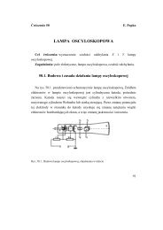
-consistent calculation algorithm shown in Fig. 2.<br />
4. Results<br />
Traditional 980-nm GaAs-based diode lasers with GaInAs/GaAs QWs exhibit a very<br />
good thermal behaviour which follows from high values of their T o parameter<br />
(21)
234 R.P. SARZAŁA<br />
Fig. 2. Flow chart of the numerical calculation.<br />
describing temperature dependence of a threshold current. Analogous properties<br />
should be also expected for considered new configurations of these devices,<br />
especially for their resonators tuned to the maximal active-region optical gain. Such<br />
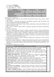
a behaviour is confirmed by Fig. 3a presenting nearly insignificant temperature-induced<br />
threshold-current increases. For the cavity tuned to the 1200-nm wave, the<br />
characteristic T o parameter is as high as 191 K for the (300 K, 350 K) temperature<br />
range and still high 133 K for (350 K, 390 K) one. Such a good thermal stabilisation<br />
of a threshold current follows from a high optical gain tuned to the cavity. Its value<br />
remains below 0.5 mA up to the active-region temperature of 360 K.<br />
Detuning of the resonator from the maximal active-region gain value is followed<br />
by a considerable RT threshold current increase: to 0.67 mA for the cavity tuned to<br />
1250 nm (Fig. 3b) and to a much higher value for the 1300-nm cavity (Fig. 3c). As<br />
expected, this current rapidly decreases with an increase in temperature, reaching for<br />
the 1250-nm cavity values below 0.35 nm for T = (325 K, 355 K) and below 1 mA<br />
for T = (402 K, 480 K) for the 1300-nm cavity. Its further increase is relatively slow<br />
(T o = 247 K and 172 K, respectively, for both the above cases). This behaviour is a<br />
direct consequence of temperature-induced shifting of the active-region optical gain<br />
towards longer wavelengths, which is followed by a better tuning to laser cavities
Physical analysis of an operation of GaInAs/GaAs... 235<br />
a<br />
b<br />
c<br />
Fig. 3. Threshold current I th as a function of the active-region temperature increase ∆T A,max over the<br />
room temperature RT = 300 K determined for VCSEL structures designed for the lasing wavelength:<br />
1200 nm (a), 1250 nm (b), 1300 nm (c). Values of the T o characteristic temperature are indicated. Active<br />
regions are the same in all VCSEL structures.<br />
(Fig. 4). As one can see in Fig. 3b and Fig. 4a, the considered VCSEL design seems<br />
to exhibit high performance as the 1250-nm laser source for a wide temperature<br />
range.
236 R.P. SARZAŁA<br />
a<br />
b<br />
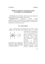
Fig. 4. Gain spectra g(λ) of the Ga 0.6 In 0.4 As/GaAs 8-nm quantum well determined for lasing-threshold<br />
conditions and two ambient temperatures: 300 K (a) and 390 K (b). Threshold voltage U th and maximal<br />
values of threshold carrier concentration n th, max are indicated. Assumed threshold gain of 600 cm –1 is<br />
shown.<br />
Analogous performance of the 1300-nm VCSEL does not meet our expectation.<br />
Its RT operation is possible only for very high operation currents, which excludes its<br />
practical significance.<br />
Figure 4 presents active-region gain spectra for selected operation conditions.<br />
Perpendicular lines correspond to resonator wavelengths. Their intersections<br />
(identified by small circles) indicate values of an optical gain available for considered<br />
designs and temperatures. Both the gain spectrum and the cavity characteristic are<br />
shifted with an increase in temperature towards longer wavelengths. But the gain<br />
spectrum (dependent on the energy gap) is shifted much more rapidly than the cavity<br />
wavelength (dependent on refractive indices and thermal expansion). For the 1200-nm<br />
cavity, the former peak is shifted at the rate of 0.52 nm/K, whereas the latter one –<br />
0.085 nm/K, which is seen comparing Fig. 4a and 4b.
Physical analysis of an operation of GaInAs/GaAs... 237<br />
At 300 K (Fig. 4a), the gain spectrum of the 1200-nm laser is quite well tunned to<br />
the laser cavity which is followed by its very low lasing threshold. Besides, an increase<br />
in the active-region temperature causes a move of the working point along the gentle<br />
-slope side of the gain spectrum. Therefore, an increase in the ambient temperature<br />
causes a relatively slow threshold-current increase, which is a reason of a very high<br />
T o value of the 1200-nm laser just over RT (Fig. 3a).<br />
Gain spectrum of the 1250-nm laser is at RT (Fig. 4a) much more detuned from<br />
its cavity wavelength which is followed by a much higher lasing threshold to raise the<br />
whole gain spectrum. But fortunately with an increase in temperature the gain spectrum<br />
is becoming closer and closer to the cavity wavelength, so the detuning is steadily<br />
reduced. It is followed by a rapid decrease in the lasing threshold (Fig. 3b): the best<br />
tuning is achieved between 330 K and 350 K, after which a relatively slow threshold<br />
increase is observed (T o =247K).<br />
Initial detuning at RT of the 1300-nm laser is very large (Fig. 4a). Its working point<br />
is situated far from the gain maximum. In this case an increase in the whole gain<br />
spectrum to reach the lasing threshold would need the extremely high threshold carrier<br />
concentration. Fortunately, an increase in the active-region temperature, being a result<br />
of high operation currents, causes an additional shift of the gain spectrum towards<br />
longer wavelengths. Nevertheless RT lasing threshold determined for this structure<br />
(Fig. 4a) is very high: RT threshold voltage is very low for the 1200-nm laser – 1.23 V,<br />
remains still quite low for the 1250-nm laser – 1.47 V, but is surprisingly high for the<br />
1300-nm laser – 7.80 V.<br />
Radial profiles of the threshold carrier concentration j th and the active-region<br />
temperature increase T A – T HS are plotted in Fig. 5 for the 1300-nm laser. As one can<br />
see, temperature profiles remain within the active-region r
238 R.P. SARZAŁA<br />
hand, becomes more and more nonuniform with an increase in T HS . Lower threshold<br />
current densities are shown at higher temperatures because an increase in temperature<br />
is followed by better matching of the cavity wavelengths and the active-region gain<br />
spectrum (c.f. Figs. 4a and 4b), therefore the threshold current is reduced (Fig. 3c). As<br />
expected, a distinct current-crowding effect is seen close to the active-region edge,<br />
especially at RT. This effect would be much more pronounced in VCSELs with larger<br />
active regions, which was analysed in earlier author’s papers [28, 29]. Therefore, to<br />
optimise this structure for a possible 1300-nm emission, relatively small active region<br />
has been chosen.<br />
5. Conclusions<br />
Physical aspects of an operation of GaAs-based GaInAs/GaAs QW VCSELs have<br />
been considered in the present paper using the comprehensive three-dimensional<br />
self-consistent optical-electrical-thermal-gain simulation. A possibility of designing<br />
1.3-µm devices has been analysed. Currently available technology has been confirmed<br />
to enable manufacturing the above devices emitting radiation of wavelengths over<br />
1.2 µm. In GaAs-based structures, very good DBR resonator mirrors and very efficient<br />
methods to confine radially both the current spreading and the electromagnetic field<br />
with the aid of oxide apertures may be applied.<br />
While high-performance 1.26-µm QW GaInAs/GaAs VCSELs may be produced<br />
using even currently available and still immature technology, analogous 1.3-µm<br />
devices seem to be still beyond its capability. Nevertheless the former devices of much<br />
higher output than their quantum-dot versions may be already used in 10 Gbps single<br />
-mode Ethernet [9] or SONET OC-192 [10] networks. It may be also expected that<br />
improved technology in future may enable also manufacturing 1.3-µm VCSELs.<br />
Acknowledgements – This work has been supported by the Polish State Committee for Scientific Research<br />
(KBN), grants No. 7-T11B-073-21 and No. 4-T11B-014-25.<br />
References<br />
[1] SARZAŁA R.P., Computer simulation of performance characteristics of (GaIn)(NAs) diode lasers,<br />
Optica Applicata 32(3), 2002, pp. 449–60.<br />
[2] KOYAMA F., SCHLENKER D., MIYAMOTO T., CHEN Z., MATSUTANI A., SAKAGUCHI T., IGA K., Data<br />
transmission over single-mode fiber by using 1.2-µm uncooled GaInAs-GaAs laser for Gb/s local<br />
area network, IEEE Photonics Technology Letters 12(2), 2000, pp. 125–7.<br />
[3] HARMAND J.C., LI L.H., PATRIARCHE G., TRAVERS L., GaInAs/GaAs quantum-well growth assisted by<br />
Sb surfactant: Toward 1.3 µm emission, Applied Physics Letters 84(20), 2004, pp. 3981–3.<br />
[4] NI H.Q., NIU Z.C., XU X.H., XU Y.Q., ZANG W., WEI X., BIAN L.F., HE Z.H., HAN Q., WU R.H.,<br />
High-indium-content In x Ga 1-x As/GaAs quantum wells with emission wavelengths above 1.25 µm at<br />
room temperature, Applied Physics Letters 84(25), 2004, pp. 5100–2.
Physical analysis of an operation of GaInAs/GaAs... 239<br />
[5] MOGG S., PLAINE G., ASPLUND C., SUNDGREN P., BASKAR K., MULOT M., SHATZ R., HAMMAR M.,<br />
High-performance 1.2-µm Highly strained InGaAs/GaAs quantum well lasers, Conference<br />
Proceedings – International Conference on Indium Phosphide and Related Materials, 2002,<br />
pp. 107–10.<br />
[6] SUNG L.W., LIN H.H., Highly strained 1.24-µm InGaAs/GaAs quantum-well lasers, Applied Physics<br />
Letters 83(6), 2003, pp. 1107–9.<br />
[7] ASPLUND C., SUNDGREN P., MOGG S., HAMMAR M., CHRISTIANSSON U., OSCARSSON V., RUNNSTRÖM C.,<br />
ODLING E., MALMQUIST J., 1260 nm InGaAs vertical-cavity lasers, Electronics Letters 38(13), 2002,<br />
pp. 635–6.<br />
[8] SCHLENKER D., MIYAMOTO T., CHEN Z.B., KAWAGUCHI M., KONDO T., GOUARDES E., KOYAMA F.,<br />
IGA K., Critical layer thickness of 1.2-µm highly strained GaInAs/GaAs quantum wells, Journal of<br />
Crystal Growth 221, 2000, pp. 503–8.<br />
[9] KUDO M., MISHIMA T., Improved photoluminescence properties of highly strained InGaAs/GaAs<br />
quantum wells grown by molecular-beam epitaxy, Journal of Applied Physics 78(3), 1995,<br />
pp. 1685–8.<br />
[10] ROAN E.J., CHENG K.Y., Long-wavelength (1.3 µm) luminescence in InGaAs strained quantum-well<br />
structures grown on GaAs, Applied Physics Letters 59(21), 1991, pp. 2688–90.<br />
[11] ABOELFOTOH M.O., BORAK M.A., NARAYAN J., Ohmic contact to p-type GaAs using Cu 3 Ge, Applied<br />
Physics Letters 75(25), 1999, pp. 3953–5.<br />
[12] UENG U.J., CHEN N.-P., JANES D.B., WEBB K.J., MCINTURFF D.T., MELLOCH M.R., Temperature<br />
-dependent behavior of low-temperature-grown GaAs nonalloyed ohmic contacts, Journal of<br />
Applied Physics 90(11), 2001, pp. 5637–41.<br />
[13] OSIŃSKI M., NAKWASKI W., [In] Vertical-Cavity Surface-Emitting Laser Devices, [Eds.] E.H. Li,<br />
K. Iga, Series on Photonics, Vol. 6, Springer , Berlin, Heidelberg 2003, p. 135.<br />
[14] SKIERBISZEWSKI C., Experimental studies of the conduction-band structure of GaInNAs alloys,<br />
Semiconductor Science and Technology 17(8), 2002, pp. 803–14.<br />
[15] BLAKEMORE J.S., Semiconducting and other major properties of gallium arsenide, Journal of Applied<br />
Physics 53(10), 1982, pp. R123–81.<br />
[16] CHOW W.W., JONES E.D., MODINE N.A., ALLERMAN A.A., KURTZ S.R., Laser gain and threshold<br />
properties in compressive-strained and lattice-matched GaInNAs/GaAs quantum wells, Applied<br />
Physics Letters 75(19), 1999, pp. 2891–3.<br />
[17] VURGAFTMAN I., MEYER J.R., RAM-MOHAN L.R., Band parameters for III–V compound<br />
semiconductors and their alloys, Journal of Applied Physics 89(11), 2001, pp. 5815–75.<br />
[18] MOUMANIS K., SEISYAN R.P., KOKHANOVSKII S.I., SASIN M.E., Light and heavy hole excitons in<br />
absorption and magnetoabsorption spectra of InGaAs/GaAs MQWs, Thin Solids Films 364(1-2),<br />
2000, pp. 249–53.<br />
[19] LANCEFIELD D., ADAMS A.R., MENEY A.T., KNAP W., LITWIN-STASZEWSKA E., SKIERBISZEWSKI C.,<br />
ROBERT J.L., Light-hole mass in a strained InGaAs/GaAs single quantum well and its pressure<br />
dependence, Journal of Physics and Chemistry of Solids 56(3-4), 1995, pp. 469–73.<br />
[20] NAKWASKI W., OSIŃSKI M., Thermal analysis of GaAs-AlGaAs etched well surface-emitting<br />
double-heterostructures lasers with dielectric mirrors, IEEE Journal of Quantum Electronics 29(6),<br />
1993, pp. 1981–95.<br />
[21] SARZAŁA R.P., NAKWASKI W., Carrier diffusion inside active regions of gain-guided vertical-cavity<br />
surface-emitting lasers, IEE Proceedings: Optoelectronics 144(6), 1997, pp. 421–5.<br />
[22] FEHSE R., TOMIĆ S., ADAMS A.R., SWEENEY S.J., O’REILLY E.P., ANDREEV A., RIECHERT H.,<br />
A quantitative study of radiative, auger, and defect related recombination processes in 1.3-µm<br />
GaInNAs-based quantum-well lasers, IEEE Journal of Selected Topics in Quantum Electronics 8(4),<br />
2002, pp. 801–10.
240 R.P. SARZAŁA<br />
[23] WENZEL H., WÜNSCHE H.-J., The effective frequency method in the analysis of vertical-cavity<br />
surface-emitting lasers, IEEE Journal of Quantum Electronics 33(7), 1997, pp. 1156–62.<br />
[24] ALEXANDER W., SHACKELFORD J., Materials Science and Engineering Handbook, CRC Press 2000.<br />
[25] NAKWASKI W., Thermal conductivity of binary, ternary, and quaternary III-V compounds, Journal<br />
of Applied Physics 64(1), 1988, pp. 159–66.<br />
[26] CHUANG S.L., Physics of Optoelectronics Devices, Wiley, New York 1995.<br />
[27] ELISEEV P.G., Line shape function for semiconductor laser modelling, Electronics Letters 33(24),<br />
1997, pp. 2046–8.<br />
[28] SARZAŁA R.P., Modeling of the threshold operation of 1.3-µm GaAs-based oxide-confined<br />
(InGa)As-GaAs quantum-dot vertical-cavity surface-emitting lasers, IEEE Journal of Quantum<br />
Electronics 40(6), 2004, pp. 629–34.<br />
[29] SARZAŁA R.P., NAKWASKI W., Optimization of 1.3 µm GaAs-based oxide-confined (GaIn)(NAs)<br />
vertical-cavity surface-emitting lasers for low-threshold room-temperature operation, Journal of<br />
Physics: Condensed Matter 16(31), 2004, S3121–40.<br />
[30] THURMOND C.D., Standard thermodynamic functions for the formation of electrons and holes in Ge,<br />
Si, GaAs, and GaP, Journal of the Electrochemical Society 122(8), 1975, pp. 1133–41.<br />
Received December 9, 2004