Lab 4 Laser - Institutt for elektronikk og telekommunikasjon - NTNU
Lab 4 Laser - Institutt for elektronikk og telekommunikasjon - NTNU
Lab 4 Laser - Institutt for elektronikk og telekommunikasjon - NTNU

You also want an ePaper? Increase the reach of your titles
YUMPU automatically turns print PDFs into web optimized ePapers that Google loves.
From<br />
pink light<br />
to red LASER<br />
<strong>Lab</strong> exercise TFE4160 Elektrooptikk <strong>og</strong> lasere<br />
<strong>NTNU</strong><br />
<strong>Institutt</strong> <strong>for</strong> <strong>elektronikk</strong> <strong>og</strong> <strong>telekommunikasjon</strong><br />
September 2004
Contents<br />
1 <strong>Lab</strong> exercise:<br />
From pink light to red LASER 3<br />
1.1 <strong>Laser</strong> safety . . . . . . . . . . . . . . . . . . . . . . . . . . . . . . 3<br />
1.1.1 Electrical hazard . . . . . . . . . . . . . . . . . . . . . . . 3<br />
1.1.2 Light hazard . . . . . . . . . . . . . . . . . . . . . . . . . 3<br />
1.1.3 Rules of thumb when working with lasers . . . . . . . . . 5<br />
1.2 <strong>Laser</strong> fundamentals . . . . . . . . . . . . . . . . . . . . . . . . . . 7<br />
1.2.1 Light amplification . . . . . . . . . . . . . . . . . . . . . . 7<br />
1.2.2 <strong>Laser</strong> resonators and standing waves . . . . . . . . . . . . 8<br />
1.3 <strong>Lab</strong> exercises . . . . . . . . . . . . . . . . . . . . . . . . . . . . . 10<br />
1.3.1 Equipment . . . . . . . . . . . . . . . . . . . . . . . . . . 10<br />
1.3.2 HeNe-tube . . . . . . . . . . . . . . . . . . . . . . . . . . 10<br />
1.3.3 HeNe-laser alignment . . . . . . . . . . . . . . . . . . . . 10<br />
1.3.4 Transversal modes . . . . . . . . . . . . . . . . . . . . . . 10<br />
1.3.5 Polarization . . . . . . . . . . . . . . . . . . . . . . . . . . 11<br />
A Output spectrum 12<br />
2
Chapter 1<br />
<strong>Lab</strong> exercise:<br />
From pink light to red LASER<br />
This lab exercise gives insight into the fundamentals of laser operation. A<br />
HeNe-discharge tube is used and aligned with a mirror to construct a laser.<br />
The fundamental properties of this laser are then investigated.<br />
1.1 <strong>Laser</strong> safety<br />
A laser can be a powerful and harmful device. It is there<strong>for</strong>e very important<br />
that the laser is handled with outmost care and that your eyes always are<br />
protected. Never look into the laser aperture nor into the reflected light from<br />
the brewster window.<br />
1.1.1 Electrical hazard<br />
The HeNe laser is pumped with a very high voltage: 1900 Volts!! There<strong>for</strong>e:<br />
Do not touch any connectors on the HeNe discharge tube. The PSU (power<br />
supply unit) feeds the tube with 7mA. This is enough to kill you if you touch<br />
both wires!! There<strong>for</strong>e, again: Do not tamper with any of the electrical wires<br />
concerning the discharge tube!<br />
1.1.2 Light hazard<br />
Do NOT stare into laser light!!<br />
This is the first and most important rule <strong>for</strong> operating lasers. A laser provides<br />
high intensity light and may just burn a hole in your retina if you look into the<br />
laser light.<br />
Since the first laser was made in 1960 it has been clear that laser emissions<br />
are a hazard to the eye and skin, more of a hazard than most other light<br />
sources. <strong>Laser</strong>s are hazardous because they produce intense directed energy<br />
that can damage living tissues. There are other common light sources strong<br />
enough to cause permanent eye or skin damage, including: direct sunlight, arc<br />
3
1.1 <strong>Laser</strong> safety 4<br />
welders, movie projectors, searchlights and special tv photo lamps.<br />
Living tissues can be damaged when they absorb light because of excessive<br />
(even explosive!) heating or by photochemical changes. Examples of heat damage<br />
include skin burned by concentrated sunlight or laser emission, and retina<br />
lesions caused by laser beams. Examples of photochemical damage includes<br />
sunburn and cataracts caused by excessive exposure to ultraviolet light from<br />
the sun or from arc welders.<br />
When you look at a strong hal<strong>og</strong>en bulb you feel that it is strong light and<br />
that you should not continue looking at it (you would see green spots <strong>for</strong> a couple<br />
of days if you continued long enough). The laser light is more concentrated<br />
and has a typical spot diameter of 300µm which, when it gets focused, makes<br />
a spot that is 10µm on your retina. Let’s now compare the light intensity of a<br />
5mW laser-pointer to the intensity from the image of the sun focused on your<br />
retina.<br />
Sun retina intensity =<br />
Power<br />
Spot size =<br />
3 · 10−3 W<br />
π(75 · 10 −6 = 180 kW/m2<br />
) 2<br />
<strong>Laser</strong> retina intensity =<br />
Power<br />
Spot size = 5 · 10−3 W<br />
π(5 · 10 −6 = 63.6 MW/m2<br />
) 2<br />
In other words: the laser retina intensity is 350 times the sun retina intensity. It<br />
is not recommended to stare at the sun, and with these calculations, I’d suggest<br />
that you don’t even think of staring into the laser light. It will burn your retina<br />
rather quickly.<br />
During this lab exercise you will handle a laser tube which is capable of<br />
delivering up to 5mW of coherent light at wavelengths around 632nm(red). It<br />
is dangerous to look into the laser beam so do not do that. You shall also wear<br />
welding glasses when working with the laser. This is to be sure that no one<br />
gets black spots on their retina due to focused laser light.
1.1 <strong>Laser</strong> safety 5<br />
Class Power Hazards Precautions Examples<br />
I ≤ 4µW None none, ”exempt” UPC Scanners<br />
II > 4µW<br />
≤ 1mW<br />
Retina damage<br />
<strong>Laser</strong>pointers,<br />
small HeNe lasers<br />
IIIa<br />
> 1mW<br />
≤ 10mW<br />
possible after 10<br />
seconds or more<br />
of steady direct<br />
viewing<br />
Retina damage<br />
possible in 0.25<br />
seconds<br />
IIIb > 10mW Retina damage<br />
≤ 0.5W likely in 0.1<br />
seconds.<br />
IV > 0.5W Severe eye or skin<br />
damage from direct<br />
exposure.<br />
Eye damage likely<br />
from indirect exposure.<br />
Can ignite flammable<br />
materials<br />
<strong>Lab</strong>elling and warnings<br />
do not stare into<br />
beam<br />
Trained operators<br />
attached beam stop<br />
warninglamp<br />
contain beams<br />
Key switch<br />
interlock connector<br />
eye protection<br />
trained personnel<br />
only<br />
emission delay<br />
intracavity shutter<br />
door interlock<br />
contain all reflections<br />
HeNe and semicounductor<br />
laserpointers<br />
Semiconductor<br />
Dye<br />
Cutters, welders<br />
laser shows<br />
pulsed lasers<br />
argon lasers<br />
Table 1.1: Summary of ANSI and CDRH <strong>Laser</strong> Classes (see Winburn 1990, Ch.<br />
6)<br />
1.1.3 Rules of thumb when working with lasers<br />
The following rules of thumb will prevent accidents that can damage vision. If<br />
in doubt of the safety of any situation, seek the advise of the lab instructor.<br />
1. Know the appropriate laser Class(see table 1.1) and necessary precautions.<br />
2. Do not look into a laser beam under any circumstances!<br />
3. Control and confine all laser beams.<br />
4. Use beam stops and carefully plan the placement and movement of optical<br />
elements.<br />
5. Beware of stray reflections from the many surfaces the beams might encounter.<br />
6. Confine the beams to the horizontal plane just above the table.<br />
7. Keep your eyes above the level of the laser beams. (see rule 7)
1.1 <strong>Laser</strong> safety 6<br />
8. Close your eyes if you bend down to pick something up from the floor.<br />
(see rule 7)<br />
9. Do not wear a watch or jewelry with shiny flat surfaces.<br />
10. Resist the impulse to look toward a flash or glare of light, it may be a<br />
laser beam illuminating your face.<br />
11. Turn room lights ON when possible. The eye’s pupils open wide in a<br />
dark room and present a larger target <strong>for</strong> a stray laser beam.<br />
12. Wear safety laser g<strong>og</strong>gles when appropriate.<br />
13. Follow laser operating instructions carefully.<br />
14. Use common sense and be alert at all times.
1.2 <strong>Laser</strong> fundamentals 7<br />
1.2 <strong>Laser</strong> fundamentals<br />
1.2.1 Light amplification<br />
Atoms and molecules interact with light in three different processes:<br />
Absorption, spontaneous emission and stimulated emission.<br />
- Absorption: An atom or molecule can capture, ”absorb”, a photon of<br />
light and be excited, converted to a higher energy level. The photon<br />
must have a specific frequency n to provide the proper amount of energy<br />
E = hν to excite the atom or molecule. This process called ”stimulated<br />
absorption” is the atom’s response to electromagnetic stimulation by the<br />
incoming photon. Stimulated absorption is responsible <strong>for</strong> the colors of<br />
dyes, which absorb light of specific frequencies, while a black or gray object<br />
absorbs all frequencies equally..<br />
- Spontaneous emission:An excited atom or molecule with excess stored<br />
energy E can release that energy spontaneously, by emission of a photon<br />
with frequency ν = E/h Spontaneous emission is responsible <strong>for</strong> the light<br />
emission by fires, fireflies, fluorescent paint, sunlight, LEDs, hot pokers,<br />
and most types of lamps.<br />
- Stimulated emission: An excited atom or molecule can be stimulated<br />
to release excess energy E in response to an incident photon of the exactly<br />
the right frequency (ν = E/h) and simultaneously release, or emit, two<br />
photons with the same frequency, using the energy of the incident photon<br />
plus the stored energy of the excited atom. Stimulated emission is the<br />
process that provides optical amplification in most lasers, since one photon<br />
in produces two photons out, an amplification factor of exactly two per<br />
event.<br />
Real atomic and molecular systems absorb or emit light at many discrete<br />
frequencies, each with a range, or bandwidth D ν centered around the main<br />
frequency ν = E/h. Optical amplification occurs when the rate of stimulated<br />
emission exceeds the rate of (stimulated) absorption, producing gain G where<br />
G =<br />
light out<br />
light in . (1.1)<br />
Amplification (G > 1) occurs in an atomic or molecular system with a population<br />
inversion, which means that the number of excited atoms (or molecules)<br />
exceeds the number of unexcited atoms or molecules. This means that there<br />
will be more stimulated emission than stimulated absorption.
1.2 <strong>Laser</strong> fundamentals 8<br />
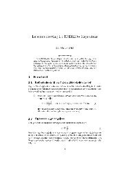
1.2.2 <strong>Laser</strong> resonators and standing waves<br />
The optical feedback and delay<br />
functions are served by an optical<br />
resonator, such as the one shown<br />
in Fig. 1.1a constructed with two<br />
mirrors that face each other. The<br />
mirrors serve to recirculate, or feed<br />
back, the light with efficiency R =<br />
R1R2, the product of the reflectivities<br />
R1 and R2 of the two mirrors.<br />
The delay time t = 2L/c is<br />
the time it takes light to complete<br />
a round trip between the mirrors.<br />
The net gain <strong>for</strong> a complete round<br />
trip is GR and must be equal to<br />
unity to sustain steady oscillation.<br />
The condition GR = 1 means that<br />
the gain compensates <strong>for</strong> the loss<br />
and the oscillator will operate with<br />
steady power. (What if GR < 1 or<br />
GR > 1?).<br />
There is an additional criterion<br />
that after each round trip the light<br />
wave crests line up with the crests<br />
from the previous round trip. This<br />
is called resonance and results in<br />
a standing wave as shown in Fig.<br />
1.1b. This condition is similar<br />
to the resonances associated with<br />
standing sound waves in an organ<br />
pipe or on a guitar string. The condition<br />
on the mirror separation is<br />
that one round trip contains an integral<br />
number of wavelengths 2L =<br />
mλ, where m is an integer. The<br />
corresponding resonant frequencies<br />
are f m = c/λ = mf fsr , where the<br />
free spectral range f fsr = c/2L is<br />
the separation between resonance<br />
frequencies. Fig. 1.1b has harmonic<br />
number m = 4, but a typical<br />
visible wavelength laser resonator<br />
might have length L = 30 cm operating<br />
at wavelength l = 600 nm<br />
so that m = 1 million.<br />
Figure 1.2a shows resonant fre-<br />
Figure 1.1a: Mirror resonator<br />
Figure 1.1b: Standing wave in a mirror<br />
resonator<br />
Figure 1.2: Typical laser output spectrum
1.2 <strong>Laser</strong> fundamentals 9<br />
quencies of an optical resonator<br />
near m = 1 million. For an L = 30 cm resonator, the spacing between successive<br />
resonance frequencies is f fsr = c/2L = 500 MHz while the resonance<br />
frequencies are near f m = c/l = 500 THz, one million times larger.<br />
The spectrum, or collection of different frequencies, emitted by a laser is<br />
a combination of the resonant frequencies f m of the many possible standing<br />
optical waves in the resonator (fig. 1.2a) with the range of frequencies in the gain<br />
spectrum (fig. 1.2b) produced by stimulated emission and population inversion.<br />
A representative laser output spectrum is shown in Fig. 1.2c. Modified laser<br />
resonators can suppress all but one of the resonant frequencies, permitting more<br />
precise control of the frequency, a desirable feature in scientific and engineering<br />
applications. The typical He-Ne laser illustrated in Fig. 1.3 consists of a sealed<br />
tube containing a mixture of helium and neon gasses and an optical resonator.<br />
An electrical discharge in the tube excites the helium atoms, which then collide<br />
with the neon atoms, transferring excess energy to pump the neon atoms from<br />
level 0 to level 2. The neon atoms develop a population inversion between<br />
levels 2 and 1, providing gain at one of several different visible and infrared<br />
wavelengths. The light circulating between the two mirrors is amplified by<br />
the stimulated emission from the excited neon atoms on each round trip. One<br />
mirror, called the back reflector, has high reflectivity(> 99%) while the other<br />
mirror, called the output coupler, has lower reflectivity (typically 95 − 98%)<br />
and transmits a fraction (2 − 5%) of the light to the outside this is the laser<br />
output that we observe. The power inside the laser is many (20 − 50) times<br />
higher than the power emitted.<br />
Figure 1.3: Construction of HeNe laser tube
1.3 <strong>Lab</strong> exercises 10<br />
1.3 <strong>Lab</strong> exercises<br />
1.3.1 Equipment<br />
Welding glasses <strong>for</strong> eye protection<br />
HeNe one-brewster discharge tube<br />
High Voltage(1900 V) power supply<br />
Alden cable with ballast resistor<br />
Output coupler-mirror (OC)99%@632.8nm<br />
Power meter<br />
Polarizer<br />
Quarter wave plate<br />
Chopper<br />
Photo diode with amplifier<br />
Oscilloscope<br />
1.3.2 HeNe-tube<br />
The HeNe-tube is mounted in a stand with the electrical wires attached. Do<br />
NOT touch any of this. The tube is very fragile and easy to break!<br />
Plug the 220V power supply unit into the wall socket and wait <strong>for</strong> the tube to<br />
ignite.<br />
Describe the color of the light that is emitted. And measure the output power<br />
from the tube with the power meter.<br />
1.3.3 HeNe-laser alignment<br />
Put the mirror onto the rail and put it 1 cm from the brewster-window. Observe<br />
the change of light color that is transmitted through the mirror. Why does the<br />
light have this color? Measure the power emitted.<br />
Now try to align the mirror so that the light gets reflected off the mirror and<br />
back through the brewster mirror so that lasing is obtained. Measure the power<br />
emitted from the laser at once when lasing is obtained. It is quite easy to see,<br />
because a flash of red light will occur when lasing starts.<br />
What is the µm readings when lasing starts? What is the effect when lasing<br />
starts? What is the maximum power that you can get out of this tube? What<br />
is the corresponding µm readings?<br />
Try to slide the mirror away from the tube. Measure and see how far you can<br />
slide while maintaining lasing. Plot the power of emitted radiation vs. length<br />
of the tube. Be careful and don’t touch the anode of the tube (High voltage)!!<br />
1.3.4 Transversal modes<br />
Look at the mode picture projected at the wall (use a sheet of paper to get a<br />
better mode picture). Which TEM mode is this? Use a lens to inflate the mode<br />
picture if it is difficult to see. What happens when the mirror is or tilted back<br />
and <strong>for</strong>th? Why?
1.3 <strong>Lab</strong> exercises 11<br />
1.3.5 Polarization<br />
Use the polarizers and the quarter wave plate to construct an analyzer. Determine<br />
the state of polarization by using an oscilloscope, the photodiode with<br />
amplifier and a chopper. What is the state of polarization? Measure also the<br />
state of polarization on the light that is reflected from the brewster window.<br />
What is the use of brewster windows? Why is the polarization state as it is?
Appendix A<br />
Output spectrum<br />
Figure A.1a shows the output spectrum of the HeNe laser. Figure A.1b shows<br />
the spectrum of the gas glow. Notice the broad spectrum and the many<br />
lines emitted. It is possible to get the the fluorescent tube lasing at both<br />
green, yellow and orange wavelengths. A blue laser may also be possible!!<br />
2500<br />
2000<br />
Effect [arb. units]<br />
1500<br />
1000<br />
500<br />
0<br />
630 635 640 645 650<br />
[nm]<br />
Figure A.1a: <strong>Laser</strong> output<br />
1200<br />
1000<br />
800<br />
Effect [arb. units]<br />
600<br />
400<br />
200<br />
0<br />
−200<br />
100 200 300 400 500 600 700 800 900<br />
[nm]<br />
Figure A.1b: Output spectrum from the gas glow outside of tube<br />
12
Bibli<strong>og</strong>raphy<br />
[Duc04] Stephen Ducharme. <strong>Lab</strong>oratory manual <strong>for</strong> physics 343: Physics of<br />
lasers and modern optics. Department of physics and astronomy, University<br />
of Nebraska-Lincoln, 2004.<br />
[ST91] Saleh and Teich. Fundamentals of photonics. Wiley, 1991.<br />
13