Techniques d'observation spectroscopique d'astéroïdes
Techniques d'observation spectroscopique d'astéroïdes Techniques d'observation spectroscopique d'astéroïdes
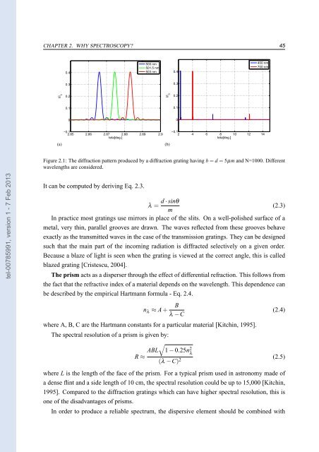
44 CHAPTER 2. WHY SPECTROSCOPY? position of the object being observed, its temperature and its internal pressure or density, its motion relative to the Earth, and the presence of a magnetic field. 2.1 Diffraction gratings and prisms There are several methods that can be used to separate the light into its component wavelengths. The simplest way is to use broad band filters before the detector in order to isolate different spectral regions. This method is called photometry and is considered as a separate subject from the spectroscopy. Spectral resolution (or resolving power) is defined as the fraction of the wavelength - ∆λ, that can be resolved relative to that of the operating wavelength - λ (Eq. 2.1). in general, the spectroscopy is considered to involve spectral resolutions higher than 50. tel-00785991, version 1 - 7 Feb 2013 R= λ (2.1) ∆λ The astronomical spectrometers are devices that measure the amount of radiation coming from the celestial bodies at different wavelengths. To split the light into its component wavelength, astronomers can use diffraction gratings, prisms, Fabry-Pérot etalons and Fourier transform spectroscopes. Bellow are summarized the main characteristics of diffraction gratings and prisms which were used during different observations that I performed. The diffraction grating generally consists of a large number N, of parallel slits separated by opaque spaces of comparable dimensions. Producing the spectra with the diffraction gratings involves the interference of N waves and the diffraction on slit phenomena [Cristescu, 2004]. The distribution of intensity of the radiation in the diffraction pattern is described by the formula Eq. 2.2. [ ] [ ] sin πbsinθ λ sin Nπ(b+d)sinθ 2 I = I 0· πbsinθ 2· λ λ sin π(b+d)sinθ (2.2) λ where d is the size of opaque spaces, b is the size of the slit, θ is the angle between a certain direction and the normal to the grating and I 0 is the total intensity passing through a slit [Cristescu, 2004]. The minima and the maxima position depend on the wavelength and on the diffraction grating parameters (b and d). By increasing the number N of slits, the interference fringes become sharpest. Two wavelengths ( λ and λ + ∆λ) could be barely separated, if the minimum of the diffraction pattern corresponding to λ is in the same position as the bright fringe corresponding to λ + ∆λ for the same diffraction order m. From this condition it can be computed the spectral resolution R=N· m. Thus the chromatic resolving power is proportional to the total number of slits and it is higher in the higher orders. In Fig. 2.1 are shown the diffraction patterns obtained using a diffraction grating having b=d = 5µm and N = 1000. The dispersion of a spectrum is the rate of change of wavelength with the angular position.
CHAPTER 2. WHY SPECTROSCOPY? 45 0.4 500 nm 501.5 nm 503 nm 0.4 400 nm 700 nm 0.3 0.3 I/I 0 0.2 I/I 0 0.2 0.1 0.1 0 0 (a) −0.1 2.85 2.86 2.87 2.88 2.89 2.9 teta[deg.] (b) −0.1 2 4 6 8 10 12 14 teta[deg.] Figure 2.1: The diffraction pattern produced by a diffraction grating having b=d = 5µm and N=1000. Different wavelengths are considered. tel-00785991, version 1 - 7 Feb 2013 It can be computed by deriving Eq. 2.3. d· sinθ λ = (2.3) m In practice most gratings use mirrors in place of the slits. On a well-polished surface of a metal, very thin, parallel grooves are drawn. The waves reflected from these grooves behave exactly as the transmitted waves in the case of the transmission gratings. They can be designed such that the main part of the incoming radiation is diffracted selectively on a given order. Because a blaze of light is seen when the grating is viewed at the correct angle, this is called blazed grating [Cristescu, 2004]. The prism acts as a disperser through the effect of differential refraction. This follows from the fact that the refractive index of a material depends on the wavelength. This dependence can be described by the empirical Hartmann formula - Eq. 2.4. n λ ≈ A+ B λ −C where A, B, C are the Hartmann constants for a particular material [Kitchin, 1995]. (2.4) The spectral resolution of a prism is given by: √ ABL 1−0.25n 2 λ R≈ (λ −C) 2 (2.5) where L is the length of the face of the prism. For a typical prism used in astronomy made of a dense flint and a side length of 10 cm, the spectral resolution could be up to 15,000 [Kitchin, 1995]. Compared to the diffraction gratings which can have higher spectral resolution, this is one of the disadvantages of prisms. In order to produce a reliable spectrum, the dispersive element should be combined with
- Page 1 and 2: OBSERVATOIRE DE PARIS ÉCOLE DOCTOR
- Page 3 and 4: OBSERVATOIRE DE PARIS ÉCOLE DOCTOR
- Page 5 and 6: OBSERVATOIRE DE PARIS ÉCOLE DOCTOR
- Page 7 and 8: tel-00785991, version 1 - 7 Feb 201
- Page 9 and 10: Résumé: L’objectif fondamental
- Page 11 and 12: tel-00785991, version 1 - 7 Feb 201
- Page 13 and 14: Acknowledgements tel-00785991, vers
- Page 15 and 16: Dedicated to mygrandfather, IosifPo
- Page 17 and 18: Contents Tables 22 Figures 27 I INT
- Page 19 and 20: 7.4.2 (3623) Chaplin . . . . . . .
- Page 21 and 22: List of Tables 2.1 The emission lin
- Page 23 and 24: List of Figures 1.1 A field obtaine
- Page 25 and 26: 5.8 Asteroid spectra and the best t
- Page 27 and 28: tel-00785991, version 1 - 7 Feb 201
- Page 29 and 30: tel-00785991, version 1 - 7 Feb 201
- Page 31 and 32: 1 Why asteroids? tel-00785991, vers
- Page 33 and 34: CHAPTER 1. WHY ASTEROIDS? 33 tel-00
- Page 35 and 36: CHAPTER 1. WHY ASTEROIDS? 35 tel-00
- Page 37 and 38: CHAPTER 1. WHY ASTEROIDS? 37 tel-00
- Page 39 and 40: CHAPTER 1. WHY ASTEROIDS? 39 the fi
- Page 41 and 42: tel-00785991, version 1 - 7 Feb 201
- Page 43: 2 Why spectroscopy? spectrum. By ca
- Page 47 and 48: CHAPTER 2. WHY SPECTROSCOPY? 47 The
- Page 49 and 50: CHAPTER 2. WHY SPECTROSCOPY? 49 0.6
- Page 51 and 52: CHAPTER 2. WHY SPECTROSCOPY? 51 −
- Page 53 and 54: CHAPTER 2. WHY SPECTROSCOPY? 53 tel
- Page 55 and 56: tel-00785991, version 1 - 7 Feb 201
- Page 57 and 58: 3 Observing techniques tel-00785991
- Page 59 and 60: CHAPTER 3. OBSERVING TECHNIQUES 59
- Page 61 and 62: CHAPTER 3. OBSERVING TECHNIQUES 61
- Page 63 and 64: CHAPTER 3. OBSERVING TECHNIQUES 63
- Page 65 and 66: 4 Spectral analysis techniques tel-
- Page 67 and 68: CHAPTER 4. SPECTRAL ANALYSIS TECHNI
- Page 69 and 70: CHAPTER 4. SPECTRAL ANALYSIS TECHNI
- Page 71 and 72: CHAPTER 4. SPECTRAL ANALYSIS TECHNI
- Page 73 and 74: CHAPTER 4. SPECTRAL ANALYSIS TECHNI
- Page 75 and 76: CHAPTER 4. SPECTRAL ANALYSIS TECHNI
- Page 77 and 78: 5 M4AST - Modeling of Asteroids Spe
- Page 79 and 80: CHAPTER 5. M4AST - MODELING OF ASTE
- Page 81 and 82: CHAPTER 5. M4AST - MODELING OF ASTE
- Page 83 and 84: CHAPTER 5. M4AST - MODELING OF ASTE
- Page 85 and 86: CHAPTER 5. M4AST - MODELING OF ASTE
- Page 87 and 88: CHAPTER 5. M4AST - MODELING OF ASTE
- Page 89 and 90: CHAPTER 5. M4AST - MODELING OF ASTE
- Page 91 and 92: tel-00785991, version 1 - 7 Feb 201
- Page 93 and 94: 6 Spectral properties of near-Earth
CHAPTER 2. WHY SPECTROSCOPY? 45<br />
0.4<br />
500 nm<br />
501.5 nm<br />
503 nm<br />
0.4<br />
400 nm<br />
700 nm<br />
0.3<br />
0.3<br />
I/I 0<br />
0.2<br />
I/I 0<br />
0.2<br />
0.1<br />
0.1<br />
0<br />
0<br />
(a)<br />
−0.1<br />
2.85 2.86 2.87 2.88 2.89 2.9<br />
teta[deg.]<br />
(b)<br />
−0.1<br />
2 4 6 8 10 12 14<br />
teta[deg.]<br />
Figure 2.1: The diffraction pattern produced by a diffraction grating having b=d = 5µm and N=1000. Different<br />
wavelengths are considered.<br />
tel-00785991, version 1 - 7 Feb 2013<br />
It can be computed by deriving Eq. 2.3.<br />
d· sinθ<br />
λ = (2.3)<br />
m<br />
In practice most gratings use mirrors in place of the slits. On a well-polished surface of a<br />
metal, very thin, parallel grooves are drawn. The waves reflected from these grooves behave<br />
exactly as the transmitted waves in the case of the transmission gratings. They can be designed<br />
such that the main part of the incoming radiation is diffracted selectively on a given order.<br />
Because a blaze of light is seen when the grating is viewed at the correct angle, this is called<br />
blazed grating [Cristescu, 2004].<br />
The prism acts as a disperser through the effect of differential refraction. This follows from<br />
the fact that the refractive index of a material depends on the wavelength. This dependence can<br />
be described by the empirical Hartmann formula - Eq. 2.4.<br />
n λ ≈ A+ B<br />
λ −C<br />
where A, B, C are the Hartmann constants for a particular material [Kitchin, 1995].<br />
(2.4)<br />
The spectral resolution of a prism is given by:<br />
√<br />
ABL 1−0.25n 2 λ<br />
R≈<br />
(λ −C) 2 (2.5)<br />
where L is the length of the face of the prism. For a typical prism used in astronomy made of<br />
a dense flint and a side length of 10 cm, the spectral resolution could be up to 15,000 [Kitchin,<br />
1995]. Compared to the diffraction gratings which can have higher spectral resolution, this is<br />
one of the disadvantages of prisms.<br />
In order to produce a reliable spectrum, the dispersive element should be combined with


