

Application Note - Ideal Industries Inc.
Application Note - Ideal Industries Inc.
Application Note - Ideal Industries Inc.

Create successful ePaper yourself
Turn your PDF publications into a flip-book with our unique Google optimized e-Paper software.
IDEAL INDUSTRIES, INC.<br />
<strong>Application</strong> <strong>Note</strong><br />
LED vs. Laser for Testing of Multimode Fiber<br />
By: Dan Payerle, Business Unit Manager<br />
The issue of testing multimode fiber with LED<br />
vs. laser light sources has been a debate since<br />
the introduction of Gigabit Ethernet in the late<br />
1990’s. The common view was that an LED<br />
source would always show the worst case loss<br />
(higher dB loss) and a laser or VCSEL (Vertical<br />
Cavity Surface Emitting Laser) would show<br />
lower losses. Lasers made the most sense when<br />
testing fiber that was intended to support<br />
Gigabit Ethernet since the networking<br />
equipment would employ lasers.<br />
An LED typically creates an overfilled launch<br />
(OFL) condition, where the core of the fiber and<br />
a good portion of the cladding are filled with<br />
light. Think of an LED as a flood light. This filling<br />
of the fiber creates a condition where bends or<br />
misalignment of connectors creates a high loss<br />
reading. The thinking is that this is the worst<br />
case scenario and it’s always better to be on the<br />
conservative side when taking measurements.<br />
However research showed that field loss<br />
measurements were often significantly higher<br />
than what networking equipment was actually<br />
exposed to.<br />
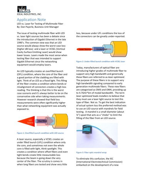
loss, because under UFL conditions the loss of<br />
the connectors can be greatly under‐reported.<br />
Figure 2: Under‐filled launch condition with VCSEL laser<br />
Today, manufacturers of optical fiber are<br />
introducing higher grades of multimode fiber to<br />
support very high bandwidth and generically<br />
these fibers are referred to as laser optimized.<br />
The purpose of these fibers is to support very<br />
high bandwidth signaling compared to early<br />
generation multimode fibers. These new fibers<br />
are categorized as OM3 and OM4, providing up<br />
to 4.7GHz*km of modal bandwidth. The term<br />
laser optimized leads installers to believe that<br />
they must use a laser light source to test this<br />
type of fiber. Not so. To get the best indication<br />
of actual system loss the preferred method was<br />
to use an LED source with mandrels for field<br />
testing. A mandrel is a small diameter (about<br />
¾”) spool that acts as a “choke” to limit the<br />
filling of the fiber from an LED source.<br />
Figure 1: Overfilled Launch condition with LED source<br />
A laser source, especially a VCSEL creates an<br />
under filled launch (UFL) condition where only<br />
the core, and sometimes not even the whole<br />
core is filled with light, think spotlight. This<br />
creates a condition where offset fibers and even<br />
tight bends create little measureable loss<br />
because the beam is going down the very<br />
center of the fiber. The scrutiny is comes in<br />
when long fibers are tested and show very little<br />
Figure 3: Fiber optic mandrel wrap<br />
To eliminate this confusion, the IEC<br />
(International Electrotechnical Commission)<br />
embarked on the development of a new
standard to define the proper testing<br />
equipment, conditions and procedures for<br />
optical fiber. The document number is the IEC<br />
14763‐3 and a good portion of it is spent<br />
defining the launch condition of light sources<br />
used to test optical fiber. In summary, to<br />
comply with the standard, a multimode light<br />
source, either LED or laser must meet the<br />
launch requirements. A light source meeting<br />
these requirements can be used to test any<br />
type of multimode fiber, eliminating the need<br />
for mandrels with LED sources and resolving the<br />
under‐reporting of link loss with laser sources.<br />
The IDEAL FiberTEK® FDX Multimode LED (Cat#<br />
33‐990‐FA01) does comply with the IEC 14763‐3<br />
launch conditions and therefore can be used to<br />
test any type of MM fiber. The Multimode<br />
Laser version (Cat# 33‐990‐FA02) does not<br />
comply with the requirements but can be used<br />
to test at the operator’s discretion. So why use<br />
the laser source at all?<br />
the IEC 14763‐3 is that its power output is going<br />
to be much lower than that of a laser. This can<br />
limit the maximum measurement distance of<br />
fiber optic links. They would be fine for<br />
applications that fall within the TIA‐568<br />
commercial building specifications (2km), but<br />
for specialized applications like CCTV over MM<br />
fiber the links can be many kilometers long. In<br />
those cases a laser source provides much<br />
greater power and thus can measure much<br />
greater distances, perhaps to 10km or more.<br />
Unique in the industry is the capability of the<br />
LanTEK® II with FiberTEK® FDX to test a single<br />
fiber in both directions at two wavelengths. This<br />
eliminates the need to swap fibers and<br />
handsets, resulting in testing times that cannot<br />
be beat.<br />
Figure 5: FiberTEK® FDX bi‐directional testing without<br />
mandrels<br />
Figure 4: LanTEK® II with FiberTEK® FDX<br />
With the adoption of the IEC fiber testing<br />
standard, a good LED source should be fine for<br />
testing most multimode installations. However<br />
one must consider the intended application.<br />
High bandwidth multimode systems are<br />
generally limited to very short distances such as<br />
data centers. So the expected loss will usually<br />
be less than 3dB. The most limiting factor of an<br />
LED light source, especially one compliant to<br />
Compliance with the IEC 14763‐3 makes this<br />
possible because adding a mandrel at each end<br />
would cause the signal to pass through two<br />
mandrels, making the test results unreliable.<br />
Contact IDEAL <strong>Industries</strong> at:<br />
www.idealindustries.com<br />
(800) 435‐0705<br />
©2009 IDEAL <strong>Industries</strong>, <strong>Inc</strong><br />
Sycamore, IL 60178


