ABC User Manual - I.C.T. Power Company Inc.
ABC User Manual - I.C.T. Power Company Inc.
ABC User Manual - I.C.T. Power Company Inc.

You also want an ePaper? Increase the reach of your titles
YUMPU automatically turns print PDFs into web optimized ePapers that Google loves.
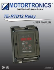
Motortronics<br />
Table of contents<br />
1 Introduction ............................................................................................................................................... 2<br />
1.1 General ............................................................................................................................................... 3<br />
1.2 Theory of Operation ............................................................................................................................ 3<br />
1.3 Brake Sizing and Selection ................................................................................................................. 3<br />
1.4 Applications ........................................................................................................................................ 5<br />
1.5 Where Mechanical Brakes Should be Used ....................................................................................... 5<br />
1.6 <strong>ABC</strong> Model Numbers, Ratings and Dimensions ................................................................................. 6<br />
2 Operation ................................................................................................................................................ 12<br />
2.1 Sequence of Operation ..................................................................................................................... 12<br />
2.2 Fault Conditions ................................................................................................................................ 14<br />
2.3 Mechanical Brake Control ................................................................................................................ 15<br />
3 Installation ............................................................................................................................................... 16<br />
3.1 Receiving and Unpacking ................................................................................................................. 16<br />
3.2 Initial Unit Inspection ........................................................................................................................ 16<br />
3.3 Location ............................................................................................................................................ 16<br />
3.3 Mounting and Cleaning ..................................................................................................................... 16<br />
4 Wiring ...................................................................................................................................................... 17<br />
4.1 Introduction ....................................................................................................................................... 17<br />
4.2 Line and Load Connections .............................................................................................................. 17<br />
4.3 Control Connections ......................................................................................................................... 20<br />
5 Adjustements ......................................................................................................................................... 23<br />
5.1 Time Adjustment Procedures ........................................................................................................... 23<br />
5.2 Jog Time Adjustment ........................................................................................................................ 23<br />
5.3 Brake Time Adjustment .................................................................................................................... 24<br />
5.4 Brake Current Adjustment ................................................................................................................ 24<br />
6 Start-Up................................................................................................................................................... 26<br />
6.1 Start-up Check List ........................................................................................................................... 26<br />
6.2 Equipment ......................................................................................................................................... 26<br />
6.3 Setup Sequence ............................................................................................................................... 26<br />
6.4 Check Normal Sequence of Operation ............................................................................................. 26<br />
APPENDIX A: TECHNICAL SPECIFICATIONS ........................................................................... 27<br />
WARRANTY INFORMATION ....................................................................................................... 29<br />
www.motortronics.com Page 1
Motortronics<br />
Your Role in Product Safety<br />
This equipment is designed and manufactured to the highest standards to provide safe and reliable operation<br />
for its intended use. Only qualified personnel should install, maintain, and service this equipment, and only after<br />
reading and fully understanding all of the information in this manual. All instructions should be strictly followed.<br />
All Warnings, Cautions, and Notes must be taken into account for your particular installation. <strong>User</strong>s should<br />
consult Motortronics or a Motortronics distributor/service center if there are any questions.<br />
All installation instructions may be superseded by applicable local, regional, or national electrical codes.<br />
Drawings, application information, and technical representations included in this manual are for typical<br />
installations, and should not in any way be considered specific to your application or conditions. Consult<br />
Motortronics for supplemental information if necessary.<br />
Contents of this manual are believed to be correct at the time of printing. In following with our on-going<br />
commitment to meeting customer needs and developing our products to suit them, Motortronics reserves the<br />
right to change specifications of this product and/or the contents of this manual without notice. As a result,<br />
supplemental data sheets and/or drawings may be associated with this equipment. Please contact Motortronics<br />
and have the unit serial number available if you notice conflicts with what is depicted in the manual and what is<br />
installed in the field.<br />
Phasetronics (dba Motortronics) accepts no liability for any consequences resulting from inappropriate, negligent,<br />
or incorrect installation, application, adjustment, or maintenance of this equipment.<br />
Notice Label Explanation:<br />
WARNING!<br />
Warning labels such as this denotes specific concerns for life/ safety/damage issues associated with this<br />
area of the manual. These statements are intended to be followed without exception.<br />
CAUTION!<br />
Caution labels are intended to alert the user to specific issues that MAY cause damage or personnel risks<br />
under circumstances as described. These items are critical in some installations but not all. The user is<br />
responsible for identifying the applicable installation issues.<br />
NOTE: Notice labels are intended to alert the user to issues that require particular attention with regard<br />
to the proper use and long term reliability of the equipment.<br />
www.motortronics.com Page 2
Motortronics<br />
1 About the Motortronics <strong>ABC</strong> Series<br />
1.1 General<br />
The <strong>ABC</strong> Series is a solid state DC injection brake for stopping three- phase AC induction motors. This full-wave<br />
DC brake design offers smooth, low peak level braking for quiet, steady operation and optimal performance.<br />
Designed to handle even high inertia loads, the <strong>ABC</strong> Series eliminates costly and potentially dangerous "coastto-<br />
stop" times. A built-in microprocessor provides system supervision that includes digital timing control for<br />
jogging and braking.<br />
The integral Operator Interface Module provides LED indication of the unit's operating status and easy<br />
adjustments for quick setup. Standard features include interlocks and mechanical brake release relays, a brake<br />
disable input and zero speed sensing with override. Installation involves simply wiring the device into the<br />
motor's starter circuit, which allows it to operate in parallel with the starter.<br />
1.2 Theory of Operation<br />
<strong>Inc</strong>oming AC power is fed to terminals L1 and L2 directly from the line side of the motor starter terminals and is<br />
converted to DC within the <strong>ABC</strong> Series. Once the motor starter has been turned off (opened) and the residual<br />
energy in the motor has dissipated, the DC current from the <strong>ABC</strong> Series is applied (injected) to starter terminals<br />
T1 and T2 respectively. This creates a stationary magnetic field in the AC motor stator windings.<br />
The braking torque will increase in proportion to the amount of current allowed to flow. The rotor continuously<br />
attempts to pull into alignment with this stationary field. This creates braking action which brings the load to a<br />
stop faster than if it coasted to a stop.<br />
1.3 Brake Sizing and Selection<br />
<strong>ABC</strong> Series brakes are suitable for use in most AC motor applications where coast-to-stop times are undesirable<br />
or unacceptable. The <strong>ABC</strong> Series is a current controlling brake, so various sizes of brake units can be applied to<br />
various motor sizes. Because DC injection means applying power to the AC motor after turning it "Off", motor<br />
heating (although minimal) will continue during the braking cycle and should be considered when selecting the<br />
motor. AC motor manufacturers recommend that each braking cycle over 100% FLA be considered as an<br />
additional starting cycle when calculating the starts- per-hour ratings for the selected motor.<br />
If the selected <strong>ABC</strong> Series is sized to deliver 200% of motor rated current, consider each brake cycle to be 2<br />
start cycles for these calculations (and 300% FLA = 3 "starts" per brake). Never size any DC injection brake to<br />
exceed 400% of the motor nameplate FLA without first consulting the motor manufacturer. Additional guidelines<br />
for applying <strong>ABC</strong> Series brakes follow:<br />
www.motortronics.com Page 3
Motortronics<br />
1.3.1 Standard Duty Sizing<br />
Applying an <strong>ABC</strong> Series brake that is rated for
Motortronics<br />
1.4 Applications<br />
The <strong>ABC</strong> Series electronic brake is ideal for machine and process equipment control applications. Benefits<br />
include, improved efficiency, increased safety, and reduced equipment maintenance costs.<br />
Efficiency is improved because you no longer have to wait through long coast-to-stop times for blade changes,<br />
batch loading, or maintenance shutdowns. Productive time increases while overall operating costs decrease<br />
because the load stops much sooner. The <strong>ABC</strong> Series eliminates the common and dangerous practice of<br />
jamming the load to a stop which seriously reduces the life and effectiveness of saw blades, molding heads, and<br />
knives.<br />
Safety is improved by eliminating the need to "jam-stop" equipment. This will prevent personnel injuries caused<br />
by kickbacks and broken blades. Use the <strong>ABC</strong> Series in conjunction with safety inter- lock devices to stop the<br />
motor as quickly as possible, reducing the risk of contact with dangerous machine elements. Prevent premature<br />
wear or component failure and eliminate the need for hasty repairs that can put maintenance personnel in<br />
potentially dangerous situations.<br />
Reduce maintenance costs by using the <strong>ABC</strong> Series. The <strong>ABC</strong> series brakes can eliminate the need to plugreverse<br />
a load and the associated damage to gear boxes and other power train components. The <strong>ABC</strong> Series<br />
can be used to stop or slow down the load in one direction before reversing to the other. On machines where<br />
mechanical brakes are used to stop or hold a load, use the <strong>ABC</strong> Series to stop it first, then set the mechanical<br />
brake as a "parking brake". This eliminates the normal wear and tear to the brake pads or shoes. On loads such<br />
as vibrating feeders, screens, or separators, damage from mechanical resonance that occur during coast-down<br />
can be eliminated by using an <strong>ABC</strong> Series. By not allowing the system to coast to a stop, the motor/load quickly<br />
pass through any dangerous speeds where resonance can occur and come to a controlled stop.<br />
1.5 Where Mechanical Brakes should be used<br />
<strong>Power</strong> loss during braking - The <strong>ABC</strong> Series, like all DC injection brakes, requires power to be applied during<br />
the braking cycle. If the incoming line power is lost, an upstream circuit protective device trips, or an emergency<br />
shutdown is initiated, no braking will take place. If braking is still necessary for safety reasons (even in the event<br />
of a power failure), consider using mechanical brakes as a backup device. Under normal operation conditions,<br />
the <strong>ABC</strong> Series stops the load and the mechanical brake holds it.<br />
Regarding holding the load after it comes to a stop - All DC injection brakes inherently lose braking torque<br />
when the motor comes to a complete stop and therefore CANNOT BE USED AS HOLDING BRAKE. If braking<br />
must be applied continuously while the load is at rest, mechanical "Parking Brakes" are required. The <strong>ABC</strong><br />
Series includes a Mechanical Brake Release Relay to facilitate proper coordination of the mechanical brake in<br />
these applications.<br />
Stop times shorter than start times - Like all DC injection brakes, the <strong>ABC</strong> Series waits for the residual motor<br />
energy to dissipate from the windings before DC current can be applied (otherwise damage to the brake or<br />
circuit devices may occur). The length of this "wait state" depends on the motor's residual magnetism and the<br />
motor frame size, but can be several seconds. This, combined with the limits on braking torque, makes DC<br />
injection braking ineffective if braking time must be shorter than the starting time (Across-the-Line).<br />
WARNING!<br />
DC Injection brakes cannot be used for holding a load after it comes to a stop. The <strong>ABC</strong> Series includes a<br />
Mechanical Brake Release Relay that can be used to coordinate the operation of a mechanical brake for<br />
use in these applications.<br />
www.motortronics.com Page 5
Motortronics<br />
1.6 <strong>ABC</strong> Series Model Number, Rating and Dimensions<br />
<strong>ABC</strong> - 200 -<br />
- E<br />
Max. Brake Amps<br />
10 – 1000 A.<br />
Voltage<br />
240 = 208 – 240V, 400 = 380 – 415V<br />
480 = 440 – 480V, 600 = 575 – 600V<br />
Enclosure<br />
P = Panel Mount<br />
E = NEMA 4/12 Sealed<br />
Model<br />
Number*<br />
Max<br />
Amps<br />
Std.<br />
Duty<br />
<strong>ABC</strong> SERIES<br />
Typical Horsepower Usage<br />
208 V 240V 480V 600V<br />
Extra<br />
Duty<br />
Std.<br />
Duty<br />
Extra<br />
Duty<br />
Std.<br />
Duty<br />
Extra<br />
Duty<br />
Std.<br />
Duty<br />
Extra<br />
Duty<br />
Panel<br />
Dim Ref.#<br />
Dimensions<br />
NEMA 4/12<br />
Dim Ref. #<br />
<strong>ABC</strong>-10 10 3 1 3 1 7.5 3 10 5 2 7<br />
<strong>ABC</strong>-24 24 7.5 3 10 5 20 10 25 15 2 7<br />
<strong>ABC</strong>-50 50 15 7.5 20 10 40 25 50 30 2 7<br />
<strong>ABC</strong>-100 100 30 20 40 25 75 50 100 60 2 7<br />
<strong>ABC</strong>-200 200 75 40 75 50 150 100 200 125 3 8<br />
<strong>ABC</strong>-300 300 100 60 125 75 250 150 300 200 4 9<br />
<strong>ABC</strong>-400 400 150 75 150 100 350 200 400 250 4 9<br />
<strong>ABC</strong>-550 550 250 125 200 150 500 300 600 350 5 10<br />
<strong>ABC</strong>-800 800 350 200 350 200 700 450 900 500 5 10<br />
<strong>ABC</strong>-1000 1000 400 250 400 300 900 500 1000 600 5 10<br />
NOTES:<br />
1. Never exceed the Full Load Amp rating of the motor without checking the motor manufacturer's data<br />
with regards to appropriateness of the application and duty cycle.<br />
2. If duty cycle is not known, Motortronics recommends using the Extra Duty Brake since braking current<br />
can be adjusted down to meet the actual load requirements.<br />
Dim<br />
Dimensions (<strong>Inc</strong>hes)<br />
Ref. # A B C D E F<br />
2 10.5 7.9 7.2 10 6.8 0.21<br />
3 16.5 10 10 15.9 9 0.28<br />
4 16 16 10 15 15 0.5<br />
5 21 26 10.4 20 25 0.5<br />
6 16 12 9 14.5 10.5 0.5<br />
7 20 16 9 18.5 14.5 0.5<br />
8 24 20 16 22.5 18.5 0.5<br />
9 36 24 16 34.5 22.5 0.5<br />
10 36 30 16 34.5 28.5 0.5<br />
www.motortronics.com Page 6
Motortronics<br />
N4/12 Outline: <strong>ABC</strong>-10/24/50/100-E<br />
N4/12 Outline: <strong>ABC</strong>-200-E<br />
www.motortronics.com Page 7
Motortronics<br />
N4/12 Outline: <strong>ABC</strong>-300/400-E<br />
N4/12 Outline: <strong>ABC</strong>-550/800-E<br />
www.motortronics.com Page 8
Motortronics<br />
Panels Outline: <strong>ABC</strong>-10/24/50/100<br />
Panels Outline: <strong>ABC</strong>-200<br />
www.motortronics.com Page 9
Motortronics<br />
Panels Outline: <strong>ABC</strong>-300/400<br />
Panels Outline: <strong>ABC</strong>-550/800<br />
www.motortronics.com Page 10
Motortronics<br />
Panels Outline: <strong>ABC</strong>-1000<br />
www.motortronics.com Page 11
Motortronics<br />
2 Operation<br />
2.1 Sequence of Operation<br />
The <strong>ABC</strong> Series brake becomes "Armed" when the motor starter turns "On” and then braking occurs when the<br />
starter is turned "Off". An Operator Interface Module has two large LEDs to indicate "Braking" or "Fault"<br />
condition, plus six smaller LEDs to indicate the following modes of operation:<br />
2.1.1 “<strong>Power</strong> On”<br />
The <strong>ABC</strong> Series brake is self-powered from the available motor branch circuit from Terminals L1 and L2. If fuses<br />
are used, this LED will indicate a blown fuse condition in either of these circuits by being off when power is<br />
applied to the starter (see section 4.2.1). This LED does NOT indicate motor starter or <strong>ABC</strong> Series brake unit<br />
operational status.<br />
2.1.2 Jog / Armed<br />
The <strong>ABC</strong> Series monitors an input wired to the motor starter which indicates the starter status (see section<br />
4.3.1). The <strong>ABC</strong> Series can be programmed to wait a specific amount of motor run time before going into the<br />
"Armed" mode by using the "Jog" feature. This feature allows for user setup and testing of systems during the<br />
jog time without the braking cycle interfering. (The "Jog" time is set via the "Jog Time" dip switches.) This LED<br />
will flash once per second until the end of the jog time. If the Motor Starter is turned off while the <strong>ABC</strong> Series is<br />
still in the "Jog" mode, the brake will NOT arm and DC injection will not take place (setting this time to zero will<br />
turn off this feature). If the motor is run longer than the "Jog Time" and the "Jog Time" expires, the <strong>ABC</strong> Series<br />
will enter the "Armed" mode (indicated when the JOG/ARMED LED illuminates in a steady state). The <strong>ABC</strong><br />
Series is now ready to begin DC injection braking the next time the motor starter is turned off. The "Armed"<br />
mode has no time limit and will be maintained for the duration of the motor run time.<br />
www.motortronics.com Page 12
Motortronics<br />
2.1.3 “Braking”<br />
After the <strong>ABC</strong> is "Armed" and the motor starter is given a STOP Commend, the <strong>ABC</strong> Series will enter the<br />
"Braking" mode (see "JOG / ARMED" above). To prevent damaging current spikes, the <strong>ABC</strong> monitors the motor<br />
until the stator magnetic field decays before DC is applied (see section 5.1). Immediately upon the motor starter<br />
opening and throughout the "BRAKING" mode, a set of N.C. interlock contacts change state (open) and disable<br />
the motor starter control circuit during the braking cycle (see section 4.2.2).<br />
The <strong>ABC</strong> Series begins injecting a True RMS regulated DC braking current and simultaneously digitally times,<br />
controls the Interlock Relay and monitors the Zero Speed Sense Circuit. Braking will continue until the first one<br />
of three events occurs: 1) the Zero Speed Sense circuit determines the motor has stopped, 2) the "Brake Time"<br />
expires, or 3) the unit receives a "Brake Disable" signal input. When braking is complete, the <strong>ABC</strong> Series<br />
releases the Interlock Relay and enters the "Brake Off" mode ready for another cycle.<br />
2.1.4 Brake OFF<br />
This LED illuminates whenever the <strong>ABC</strong> Series is not actively braking (either because the motor is on or the<br />
previous braking cycle has been completed). The <strong>ABC</strong> Series provides a built-in, closed-loop sensing circuit that<br />
accurately determines when the motor has stopped based on the subtle signals received from the unused motor<br />
winding. If the Zero Speed Sensing circuit determines that the motor has come to a stop before the Brake Time<br />
has expired, it will override the brake time setting and shut the <strong>ABC</strong> Series off. The "BRAKE OFF" LED will then<br />
illuminate. NOTE: Since the Brake Time may expire prior to the Zero Speed override coming into play, this<br />
circuit should not be used as a true Zero Speed indicator.<br />
WARNING!<br />
The <strong>ABC</strong> Series DC Injection Brake requires AC power for braking. <strong>Power</strong> loss before or during braking<br />
will result in the loss of braking ability, which can be hazardous to personnel and/or equipment. If braking<br />
to a stop is critical regardless of the availability of electrical power, mechanical braking should be<br />
provided as a backup system. The <strong>ABC</strong> Series brake offers a Mechanical Brake Release Relay specifically<br />
for this purpose.<br />
www.motortronics.com Page 13
Motortronics<br />
2.2 Fault Conditions<br />
The “FAULT” LED will illuminate when any of the following conditions occur:<br />
2.2.1 “Disabled”<br />
The "DISABLED" mode is activated when the <strong>ABC</strong> Series receives a command on the Brake Disable input (a<br />
N.O. dry contact at TB1) (see section 4.3.2). This mode can be used to remove the electronic brake from the<br />
system, and is useful in applications that only require braking at certain times during the process and during<br />
system setup. It can also be used to cancel a "Braking" cycle that is already in progress. Note: The <strong>ABC</strong> Series<br />
is a "smart brake" and will sense a running motor and automatically arm itself if released from the "DISABLED"<br />
mode. Under these circumstances, the <strong>ABC</strong> Series will go through the "JOG" and "ARMED" sequence again. If<br />
the unit has determined the motor is stopped, the brake will return to the normal ready state.<br />
NOTE: The <strong>ABC</strong> Series Mechanical Brake Release Relay will set the mechanical brake if the <strong>ABC</strong> Series<br />
brake unit is disabled during the braking mode. Some interface wiring may be needed depending on the<br />
voltage and current rating of the mechanical brake coil.<br />
2.2.2 “Wiring Error”<br />
The <strong>ABC</strong> Series unit will recognize when the interface connections or monitored signals are not correct with<br />
respect to the proper operation sequence. If the brake detects a miswire or an improper sequence of events, it<br />
will "self-disable" to prevent any conflicts with the existing systems and indicate "WIRING ERROR". If this<br />
occurs, the "Fault" LED and "Wiring Error" LEDs will illuminate. Once the miswire or wrong sequence is<br />
corrected, the brake will automatically enable itself and resume normal operation.<br />
2.2.3 “Over Temp”<br />
The <strong>ABC</strong> Series has thermal sensors built into the heat sink assembly. If the heat sink approaches temperatures<br />
too high for the SCRs, the sensors will cause a Fault, shut down the brake and illuminate the "Fault" and "Over<br />
Temp" LEDs.<br />
www.motortronics.com Page 14
Motortronics<br />
2.3 Mechanical Brake Control<br />
The <strong>ABC</strong> Series includes a Mechanical Brake Release Relay that can be utilized to control an electromechanical<br />
brake coil. This relay has a Form “A” contact (1 N.O.) that changes state as follows (see section<br />
4.3.4):<br />
OPERATION<br />
<strong>Power</strong> On<br />
RELAY STATUS<br />
No Change (de-energized)<br />
Jog / Armed<br />
Energizes, follows motor starter (Closes)<br />
Braking<br />
Braking Time Completed /<br />
Zero Speed Override<br />
Remains energized (Closed)<br />
De-energizes (Opens)<br />
Disabled – Before or During Jog / Armed<br />
Follows motor starter<br />
Disabled – During Braking<br />
De-energizes (Opens)<br />
Fault<br />
De-energizes (Opens)<br />
www.motortronics.com Page 15
Motortronics<br />
3 Installation<br />
3.1 Receiving and Unpacking<br />
Upon receipt of the product you should immediately do the following:<br />
• Carefully unpack the unit from the shipping carton and inspect it for shipping damage.<br />
• Verify that the model number on the unit matches your purchase order.<br />
• Check all electrical terminals to be sure no connections were damaged during shipping.<br />
3.2 Initial Unit Inspection<br />
Complete a visual check of the unit for damage which may have occurred during shipping and handling. Report<br />
any damage immediately and file a claim with the freight carrier within 15 days of receipt. Do not attempt to<br />
continue installation.<br />
CAUTION!<br />
Do not operate or install the <strong>ABC</strong> Series Brake if it appears to be damaged or visually defective. Doing so<br />
may result in personnel injury or equipment damage.<br />
3.3 Location<br />
Proper location of the <strong>ABC</strong> Series is necessary to achieve specified performance and normal operation lifetime.<br />
The unit should always be installed in an area where the following conditions exist:<br />
• Ambient operating temperature:<br />
Ventilated Enclosure: 0 to 50°C (32 to 122°F)<br />
Non-Ventilated Enclosure: 0 to 40°C (32 to 104°F)<br />
• Humidity: 5 to 95% non-condensing<br />
• Free from metallic particles, conductive dust and corrosive gas<br />
• Free from excessive vibration (below 0.5G)<br />
• Open panel units must be mounted in the appropriate type of enclosure. Enclosure size and type must be<br />
suitable for environmental conditions and heat dissipated by the unit. Contact factory for details.<br />
3.4 Mounting and Cleaning<br />
The unit is air cooled and must be properly mounted to allow for unrestricted airflow across the heat sink. The<br />
unit must be mounted with the heat sink fins in a vertical plane, with a minimum of five (5) inches (127mm) of<br />
free space around the unit for adequate ventilation. The ambient air should be free of any contaminants which<br />
can clog louvers or coat the unit. As with all electrical equipment, the unit must be protected from water and<br />
condensing humidity to prevent possible damage. In damp or cold environments, space heaters may be<br />
required.<br />
WARNING!<br />
Remove All Sources of <strong>Power</strong> Before Cleaning the Unit. In dirty or contaminated atmospheres the unit<br />
should be cleaned on a regular basis to ensure proper cooling. Do not use any chemicals to clean the<br />
unit. To remove surface dust, use 80 to 100 psi clean, dry compressed air only. A three inch, high<br />
quality, dry paint brush is helpful to loosen up the dust prior to using compressed air on the unit.<br />
www.motortronics.com Page 16
Motortronics<br />
4 Wiring<br />
4.1 Introduction<br />
• Installation of the brake unit should be done by properly qualified personnel.<br />
• Check local and other applicable codes to ensure that all installation requirements are met prior to operation.<br />
• Prior to beginning the installation, verify that the motor and brake unit have the same voltage ratings.<br />
• Check the unit to verify that it is rated for the appropriate current (approximately equal to the motor FLA if<br />
sized for Standard Duty - see section 1.3).<br />
WARNING!<br />
Do not service equipment with voltage applied! Unit can be source of fatal electrical shocks! To avoid<br />
shock hazard, disconnect main power before working on the unit. Warning labels must be attached to<br />
terminals, enclosure and control panel to meet local codes.<br />
4.2 Line and Load Connections<br />
<strong>Power</strong> conductors for the Brake Line and Load connections should be, at a minimum, sized at 125% of the<br />
current rating. Brake sizing and duty cycling should be considered when determining if conductors should be<br />
oversized for your application. For example, high torque, fast stop applications with maximum duty cycle may<br />
require conductors sized for the maximum output capability of the <strong>ABC</strong> Series, and motor lead wires should<br />
match.<br />
www.motortronics.com Page 17
Motortronics<br />
4.2.1 Line <strong>Power</strong> Connections<br />
Connect the line leads to the input terminals L1 and L2 provided on the unit. The line power must be supplied<br />
from a source with suitable Short Circuit Protective Devices (SCPD) conforming to local and national electric<br />
codes.<br />
Additional fusing is necessary only when the motor circuit is fused at a level too high to protect the <strong>ABC</strong> Series<br />
per code. Recommendations for commonly available SCPDs are as follows:<br />
Unit<br />
Circuit Breaker<br />
Time Delay Fuse<br />
Class RK5<br />
Non-Time Delay Fuse<br />
Class J<br />
<strong>ABC</strong>-10 - 50A 50A<br />
<strong>ABC</strong>-24 - 50A 50A<br />
<strong>ABC</strong>-50 - 225A 225A<br />
<strong>ABC</strong>-100 - 225A 225A<br />
<strong>ABC</strong>-200 - 300A 300A<br />
<strong>ABC</strong>-300 1200A 1600A 900A<br />
<strong>ABC</strong>-400 1200A 1600A 900A<br />
<strong>ABC</strong>-550 150% of Max. Unit Rating 150% of Max. Unit Rating 200% of Max. Unit Rating<br />
<strong>ABC</strong>-800 150% of Max. Unit Rating 150% of Max. Unit Rating 200% of Max. Unit Rating<br />
<strong>ABC</strong>-1000 150% of Max. Unit Rating 150% of Max. Unit Rating 200% of Max. Unit Rating<br />
WARNING!<br />
Many motor safety disconnect switches are not rated to interrupt DC current. Replace any load side safety<br />
disconnect switch with one that is rated for DC voltage at the motor line voltage rating or greater. As an<br />
alternative, disconnect incoming line power before opening any load side disconnect switches in the<br />
motor circuit during braking, and post warning labels at all affected devices. Failure to observe this<br />
precaution may result in damage to the disconnect and /or bodily injury<br />
www.motortronics.com Page 18
Motortronics<br />
4.2.2 <strong>Power</strong> Connections<br />
The <strong>ABC</strong> Series unit will operate on either a Wye or a Delta connected motor.<br />
Connect the brakes L1 & L2 input terminals to the L1 & L2 terminals on the motor starter.<br />
Connect the T1 and T2 brake output terminals to the T1 and T2 terminals on the Motor starter.<br />
An additional sensing wire must be run from T3 (W) terminal of the starter to the voltage sensing circuit of the<br />
<strong>ABC</strong> Series labeled T3. This terminal carries very little current so a #14 wire can be used. Proper fuse protection<br />
for the field wiring must be provided per code.<br />
NOTE: If the <strong>ABC</strong> Series brake is being used with 2-speed, Wye- Delta or Reduced Voltage starter, consult<br />
factory for additional load connection information.<br />
CAUTION!<br />
<strong>Power</strong> Factor Correction Capacitors should NOT be connected to the load side of the motor starter when<br />
used with an <strong>ABC</strong> Series brake. PFC Capacitors should only be connected to the line side and must<br />
include a separate isolation contactor.<br />
www.motortronics.com Page 19
Motortronics<br />
4.3 Control Connections<br />
Control wire should be twisted, shielded cables and run in a separate conduit from power lines. Whenever<br />
possible, conduits containing control and power conductors should cross at right angles to each other. Control<br />
connections are made at terminal blocks mounted on the printed circuit boards inside the unit case. TB1 is on<br />
the Logic Board with the terminals for the Starter Monitor (Brake Command) and Brake Disable inputs. TB2 is<br />
located on the <strong>Power</strong> Board, and provides terminals for the Interlock Contacts and Mechanical Brake Relay.<br />
WARNING!<br />
The motor starter must never be operated manually when the brake unit is connected. Blown fuses and/or<br />
damage to the unit may result.<br />
4.3.1 Starter Monitor Input<br />
Provides a status signal from the motor starter to the CPU (refer to sections 2.1.2 & 2.1.3). Connect either the<br />
normally open, or normally closed (user preference) dry auxiliary contact on the motor starter to TB1, terminals 1<br />
and 2 on the logic board. To utilize a normally closed contact select Jumper X1 (factory default). For a normally<br />
open contact, move the Jumper to X2. For reversing starters, use 2 N.O. contacts in parallel or 2 N.C. contacts in<br />
series (1 from each contactor) to this input. Circuit voltage potential: 15VDC maximum.<br />
www.motortronics.com Page 20
Motortronics<br />
4.3.2 Brake Disable Input<br />
Disables electronic braking functions before, during, or after operation (refer to section 2.2.1). To utilize this<br />
feature, wire a N.O. dry contact to TB1 terminals 3 and 4 on the logic board. The disable feature will activate as<br />
long as the contact is closed, and will resume operation sequence only when the disable command is released<br />
(i.e. the contact is opened). Once the <strong>ABC</strong> Series has resumed operation, it will evaluate the status of the motor<br />
starter, re-enter the "JOG" mode and "ARM" if conditions are correct. Circuit voltage potential: 15VDC maximum.<br />
Note: The Brake Disable can and should be used to disable the <strong>ABC</strong> Series brake in the event of a motor<br />
thermal overload by wiring normally open contacts from the overload relay to these terminals. This<br />
will prevent the brake from operating if a motor over- load trip condition occurs.<br />
www.motortronics.com Page 21
Motortronics<br />
4.3.3 Interlock Contacts<br />
The <strong>ABC</strong> Series unit MUST be interlocked with the motor starter coil circuit to disable the motor starter during<br />
the braking cycle for proper operation (refer to 2.1.3). Two sets of "FORM C" contacts are provided on TB2 on<br />
power board to interlock the motor starter with the brake. Terminals 1, 2, and 3 are the first set and terminals 4,<br />
5, and 6 are the second. Use both sets for reversing starters, each in one of the contactor coil circuits. The<br />
second set may be used as a status indicator in non-reversing starter applications. Never connect the interlock<br />
contacts parallel to the contactor coil or across the power line. Circuit voltage potential: same as starter control<br />
circuit, 240VAC maximum.<br />
WARNING!<br />
If this wiring is done incorrectly or not at all, severe damage to the unit may occur and the warranty on<br />
the unit may be voided.<br />
4.3.4 Mechanical Brake Release Relay<br />
The <strong>ABC</strong> Series brake unit can work in conjunction with a mechanical brake by interfacing with the motor and<br />
allowing for mechanical brake control. The <strong>ABC</strong> Series brake can be used for stopping, and the mechanical<br />
brake for holding. The Mechanical Brake Release contacts are N.O. relay contacts rated for 5A, 250VAC and are<br />
located at terminals 7 and 8 of TB2 on the <strong>Power</strong> Board (see section 2.3 for additional operating details).<br />
The unit will detect the motor start command and release the mechanical brake. When the stop command is<br />
given, the <strong>ABC</strong> Series brake unit will continue to keep the mechanical brake released, proceed with the DC<br />
injection braking sequence, then engage the mechanical brake at the end of the braking cycle. If the disable<br />
feature is engaged while in "BRAKING" mode, the <strong>ABC</strong> Series will automatically set the mechanical brake.<br />
www.motortronics.com Page 22
Motortronics<br />
5 Adjustments<br />
5.1 Time Adjustment Procedures<br />
Time settings for "Jog Time" and "Brake Time" are adjusted by use of dip switches on the front mounted Operator<br />
Interface Module. Time settings are in seconds (set in binary code). Each switch denotes a binary digit from1- 7<br />
positions, totalling 127 seconds maximum when all are switched to the "On" position.<br />
Operator Interface Module<br />
5.2 Jog Time Adjustment<br />
Factory Setting: 3 seconds<br />
The jog time is adjustable from 0-127 seconds and is made using the 7 position dip switch SW2, labeled "Jog<br />
Time". Set the switches according to the jog time required. Setting all the switches to the "Off" position (Jog<br />
Time = 0) will disable this function.<br />
Switch Positions<br />
Example:<br />
On<br />
Setting dip switch positions 1, and 2 to “ON” = 1+2<br />
Jog Time<br />
= 3 seconds total jog time.<br />
1 2 3 4 5 6 7<br />
Time (sec.) 1 2 4 8 16 32 64<br />
CAUTION!<br />
Damage to the motor, equipment, brake and/or electrical circuit may occur if this adjustment is not<br />
correct. Setting this switch to less than the factory setting may involve risk to the equipment and affect<br />
normal operations. Setting the jog time too long may result in equipment operating without the benefit of<br />
the DC injection brake. The jog time should typically be set to equal the time it takes the motor to<br />
accelerate the load to full speed (across- the-line) plus approximately two seconds.<br />
www.motortronics.com Page 23
Motortronics<br />
5.3 Brake Time Adjustment<br />
Factory Setting: 7 seconds<br />
The brake time is programmable from 1 to 127 seconds. Set the switches marked "Brake Time" to the brake<br />
time required. Typical brake time settings should be 1/2 of the load's coast-to-stop time or less, as necessary.<br />
Each dip switch represents a binary time value. Add the times together for the final brake time setting<br />
Example:<br />
Switch Positions<br />
On<br />
Setting dip switch positions 1, 2, and 3 to "ON" = 1+2+4<br />
Brake Time<br />
= 7 seconds total brake time.<br />
1 2 3 4 5 6 7<br />
Time (sec.)<br />
1 2 4 8 16 32 64<br />
NOTE: Stop times shorter than 4 seconds will not allow enough time for the Zero Speed Sensing circuit to<br />
accurately sense that the motor has stopped. For stopping times shorter than 4 seconds, Brake Time must be<br />
used to turn the <strong>ABC</strong> Series off to insure proper stopping.<br />
5.4 Brake Current Adjustment<br />
Factory Setting: 50% of Unit Rating<br />
It is strongly recommended that you try the factory settings first before making any adjustments. First determine<br />
if adjustments are necessary by verifying the motor came to a stop during the braking cycle. If not, first increase<br />
the Brake Time setting and repeat the test. If after increasing the Brake Time setting to the desired maximum the<br />
motor still does not come to a stop during braking, increasing the Brake Current may be necessary. To do so, a<br />
"True" RMS AC clamp-on ammeter is needed to measure the current supplied to the motor while braking. To<br />
monitor the current, place the meter on one of the <strong>ABC</strong> Series' input power lines. Start the motor by energizing<br />
the motor starter contactor. Allow the motor to come up to full speed with the normal load. Engage the brake by<br />
de-energizing (stopping) the motor starter contactor. Then, measure the brake current. If necessary, slowly<br />
adjust the brake torque potentiometer (P1) (located in the Operation Interface Module) clockwise to increase the<br />
braking current. The braking Current and Time Settings should be adjusted so that the braking time expires at<br />
the same time the motor stops. Adjust the brake Time and/or Current until acceptable. Start and stop the motor<br />
several times to verify proper operation.<br />
WARNING!<br />
Never exceed the RMS full load current rating of the motor without first checking with the motor manufacturer for<br />
the maximum allowable amount of DC current that can be supplied to the motor during braking application.<br />
www.motortronics.com Page 24
Motortronics<br />
Application Specific Adjustments<br />
CAUTION!<br />
These settings are factory preset to provide optimum performance in a wide variety of applications, and should<br />
not be changed unless the user is specifically aware of the risks and consequences (contact factory for details).<br />
Disconnect all incoming power and observe anti-static control measures when making any of the following<br />
configuration changes.<br />
Brake On Delay (Switch SW1)<br />
This DIP switch controls the amount of time the <strong>ABC</strong> Series brake waits prior to applying DC current to the motor<br />
windings. It is Factory Configured for the Automatic Mode in order to allow the stator magnetic field to decay.<br />
The rate of decay varies with motor size, so this SHOULD NOT BE CHANGED. Changing this setting could<br />
result in damage to the <strong>ABC</strong> Series components and circuit protective devices. If your application requires a<br />
specific delay time, please contact the factory for assistance.<br />
Zero Speed Sensing Disable (Jumper X3)<br />
If for some reason you need to disable the Zero Speed Sensing, remove this jumper. The <strong>ABC</strong> Series will then<br />
continue braking for the entire Brake Time setting, even if the motor has already come to a complete stop. DO<br />
NOT disconnect the sensing lead to the "T3" terminal as that will cause a "Wiring Error" fault disabling the brake.<br />
Therefore this should not be used as a means of disabling the Zero Speed Sense circuit.<br />
50 Hz Operation (<strong>Power</strong> Board Jumper X1)<br />
Remove this jumper on units required to operate at 50 Hz.<br />
CAUTION!<br />
Some adjustments and devices visible on the <strong>ABC</strong> Series boards are preset at the factory and should NOT<br />
be field adjusted without specific instructions from factory authorized service personnel. These devices<br />
include: P1 and P2 potentiometers, and push button PB1. Tampering or altering these devices may void<br />
your warranty.<br />
www.motortronics.com Page 25
Motortronics<br />
6 Start-up<br />
6.1 Start-up Check List<br />
• Verify that the supply voltage matches the supply voltage of the <strong>ABC</strong> Series brake.<br />
• Confirm that the power lines are attached to the input terminals.<br />
• Verify that the output leads are connected to the output terminals.<br />
• Complete the appropriate control and interlock connections.<br />
• Clear the area of people and extra parts before start up.<br />
NOTE: For 50 Hz operation, be sure that jumper X1on the <strong>Power</strong> Board is removed.<br />
6.2 Equipment<br />
The following equipment will be needed for start-up:<br />
• A "true" RMS AC clamp-on ammeter to check braking current.<br />
• A small screw driver to adjust braking torque (if necessary).<br />
• A digital volt meter.<br />
• Stop watch or other means of measuring time.<br />
6.3 Setup Sequence<br />
• Start the motor by energizing the motor starter.<br />
• Allow the programmed jog time to expire. (Factory set for 3 sec.)<br />
• De-energize the motor starter to initiate brake mode.<br />
• Monitor the input current to the <strong>ABC</strong> Series unit on any one of its input leads with the "true" RMS AC<br />
clamp-on ammeter.<br />
• Adjust the brake current if necessary.<br />
• If the brake times out before the motor stops, increase the value of the brake time switch, or increase the<br />
brake current (Note: Never exceed the RMS rating of the motor without checking with the motor<br />
manufacturer).<br />
• If the Zero Speed Sense option engages and turns off the brake before the programmed brake time<br />
expires, adjust the brake time dip switch for approximately two (2) seconds longer than the actual stop<br />
time.<br />
6.4 Check Normal Sequence of Operation<br />
Apply power to the system. The "<strong>Power</strong> On" LED should indicate that the line power is correct. Both the "<strong>Power</strong><br />
On" and the "Brake Off" LED should be illuminated.<br />
• Start the motor. The "Jog / Armed" LED should flash once per second to indicate programmed Jog Time.<br />
• Allow the motor to run until the "Jog / Armed" LED should light solid.<br />
• Initiate the motor stop command. The "Brake Off" LED should go out and the "Brake On" LED should<br />
illuminate. The unit should begin braking and continue braking, until the motor comes to a stop or the<br />
programmed brake time expires.<br />
www.motortronics.com Page 26
Motortronics<br />
APPENDIX A: Technical Specifications<br />
Voltage Rating: Models rated from 208 – 600 +/- 10%<br />
Line Frequency:<br />
Selectable for 50 / 60 Hz + 2Hz<br />
Current Ratings:<br />
Output Capacity:<br />
<strong>Power</strong> Circuit:<br />
10 – 1000A<br />
10, 24, 50, 100, 200, 300, 400, 550, 800, 1000A<br />
25% duty cycle at 100% unit rating. 10A-400A are UL duty cycles.<br />
10& 24A = 100%<br />
50 thru 200A = 25%<br />
300A thru 800A = 15%<br />
1000A = 25%<br />
Full wave bridge, 4 SCRs, designed for use without isolation<br />
contactors.<br />
Transient Protection:<br />
Fusing:<br />
Control Circuit:<br />
Control Method:<br />
Operator Adjustments:<br />
Adjustment Ranges:<br />
Inputs:<br />
Inputs:<br />
RC snubber dv/dt circuit on each SCR device.<br />
Refer to section 4.2.1 for branch circuit protection requirements.<br />
Self-powered directly from line terminals. No separate control<br />
voltage required.<br />
Microprocessor unit control sequencing, I/O monitoring and status<br />
annunciation. Braking current is adjustable via true RMS regulated<br />
control using phase angle firing of SCRs.<br />
Brake Time and Jog Time = 7 position binary dip-switch.<br />
Brake Current = potentiometer<br />
Brake Jog Time = 0 – 127 seconds in 1 sec. increments.<br />
Brake Current = Up to 100% of unit rating.<br />
Starter Monitor = Dry input for auxiliary contact from motor starter.<br />
Jumper selectable for N.O. or N.C. contact.<br />
Brake Disable = Dry input for N.O. contact to disable braking before<br />
or during operation. Can be wired to the starter thermal overload<br />
N.O. auxiliary contact to prevent braking of overloaded motor.<br />
Motor <strong>Power</strong> Sensor (T3) = Voltage input used for sensing motor<br />
power presence in sequencing / status circuit and for zero speed<br />
sensing during braking.<br />
www.motortronics.com Page 27
Motortronics<br />
Outputs:<br />
Starter Coil Interlock = Two sets of FORM “C” relay contacts for use<br />
in interlocking the starter coil and/or other devices to prevent<br />
energizing while the braking power is applied.<br />
Mechanical brake Release = N.O. relay contact for use in controlling<br />
electro-mechanical brake as a holding brake. When the <strong>ABC</strong> Series<br />
is “disabled”, this circuit controls the mechanical brake normally as if<br />
it is the only brake in the system.<br />
Aux. Contact Ratings:<br />
LED Status Indicators:<br />
5 Amps, 250 VAC max.<br />
Large LEDs: braking = green; Fault = Red<br />
Small LEDs: <strong>Power</strong> On, Jog/Armed, Brake Off, Disabled, Over<br />
Temp and Wiring Error.<br />
Operating Design Temperature: 32ºF – 122ºF / 0ºC to 50ºC<br />
Storage Temperature: -4ºF – 176ºF / -20ºC to 80ºC<br />
Ambient Conditions:<br />
Approval:<br />
5% to 95% relative humidity<br />
0 – 3300ft (1000m) elevation<br />
UL, cUL Listed<br />
www.motortronics.com Page 28
Motortronics<br />
Warranty information<br />
Motortronics warrants its products to be free from defects in material and/or workmanship for a period of one<br />
year from the date of installation, to a maximum of 18 months from the date of shipment as indicated by the<br />
unit's date code. The <strong>Company</strong> reserves the right to repair or replace any mal- functioning units under warranty<br />
at their option. All warranty repairs must be performed by the <strong>Company</strong> factory or on site by factory authorized<br />
service firms or personnel approved by the <strong>Company</strong>.<br />
Solid state controls have different operating characteristics from those of electromechanical equipment. Because<br />
of these differences and the wide variety of applications for solid state controls, each application designer must<br />
verify that the solid state equipment is acceptable for his application. In no event will Motortronics be liable or<br />
responsible for indirect or consequential damages resulting from the use or application of this equipment. The<br />
diagrams and illustrations in this document are included solely for illustrative purposes. Because of the number<br />
of different applications, Motortronics cannot be responsible or liable for actual use based on the examples or<br />
diagrams.<br />
www.motortronics.com Page 29
For the latest product information<br />
visit www.motortronics.com<br />
Phasetronics <strong>Inc</strong>. dba as Motortronics<br />
1600 Sunshine Drive<br />
Clearwater, Florida 33765<br />
USA<br />
Tel: 727.573.1819 or 888.767.7792<br />
Fax: 727.573.1803 or 800.548.4104<br />
E-Mail: sales@motortronics.com<br />
<strong>Manual</strong> 0011002<br />
Rev 2.0.0.4<br />
08/30/12