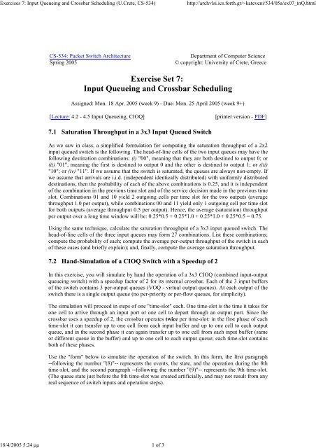
Exercises 7: Input Queueing and Crossbar Scheduling (U.Crete - ICS
Exercises 7: Input Queueing and Crossbar Scheduling (U.Crete - ICS
Exercises 7: Input Queueing and Crossbar Scheduling (U.Crete - ICS

You also want an ePaper? Increase the reach of your titles
YUMPU automatically turns print PDFs into web optimized ePapers that Google loves.
<strong>Exercises</strong> 7: <strong>Input</strong> <strong>Queueing</strong> <strong>and</strong> <strong>Crossbar</strong> <strong>Scheduling</strong> (U.<strong>Crete</strong>, CS-534)<br />
18/4/2005 5:24 µµ 1 of 3<br />
http://archvlsi.ics.forth.gr/~kateveni/534/05a/ex07_inQ.html<br />
CS-534: Packet Switch Architecture<br />
Spring 2005<br />
Department of Computer Science<br />
© copyright: University of <strong>Crete</strong>, Greece<br />
Exercise Set 7:<br />
<strong>Input</strong> <strong>Queueing</strong> <strong>and</strong> <strong>Crossbar</strong> <strong>Scheduling</strong><br />
Assigned: Mon. 18 Apr. 2005 (week 9) - Due: Mon. 25 April 2005 (week 9+)<br />
[Lecture: 4.2 - 4.5 <strong>Input</strong> <strong>Queueing</strong>, CIOQ]<br />
[printer version - PDF]<br />
7.1 Saturation Throughput in a 3x3 <strong>Input</strong> Queued Switch<br />
As we saw in class, a simplified formulation for computing the saturation throughput of a 2x2<br />
input queued switch is the following. The head-of-line cells of the two input queues may have the<br />
following destination combinations: (i) "00", meaning that they are both destined to output 0; or<br />
(ii) "01", meaning the first is destined to output 0 <strong>and</strong> the other is destined to output 1; or (iii)<br />
"10"; or (iv) "11". If we assume that the switch is saturated, the queues are always non-empty. If<br />
we assume that arrivals are i.i.d. (independent identically distributed) with uniformly distributed<br />
destinations, then the probability of each of the above combinations is 0.25, <strong>and</strong> it is independent<br />
of the combination in the previous time slot <strong>and</strong> of the service decision made in the previous time<br />
slot. Combinations 01 <strong>and</strong> 10 yield 2 outgoing cells per time slot for the two outputs (average<br />
throughput 1.0 per output), while combinations 00 <strong>and</strong> 11 yield only 1 outgoing cell per time slot<br />
for both outputs (average throughput 0.5 per output). Hence, the average (saturation) throughput<br />
per output over a long time window will be: 0.25*0.5 + 0.25*1.0 + 0.25*1.0 + 0.25*0.5 = 0.75.<br />
Using the same technique, calculate the saturation throughput of a 3x3 input queued switch. The<br />
head-of-line cells of the three input queues may form 27 combinations. List these combinations;<br />
compute the probability of each; compute the average per-output throughput of the switch in each<br />
of these cases (<strong>and</strong> briefly explain); <strong>and</strong>, finally, compute the average saturation throughput.<br />
7.2 H<strong>and</strong>-Simulation of a CIOQ Switch with a Speedup of 2<br />
In this exercise, you will simulate by h<strong>and</strong> the operation of a 3x3 CIOQ (combined input-output<br />
queueing switch) with a speedup factor of 2 for its internal crossbar. Each of the 3 input buffers<br />
of the switch contains 3 per-output queues (VOQ - virtual output queues). At each output of the<br />
switch there is a single output queue (no per-priority or per-flow queues, for simplicity).<br />
The simulation will proceed in steps of one "time-slot" each. One time-slot is the time it takes for<br />
one cell to arrive through an input port or one cell to depart through an output port. Since the<br />
crossbar uses a speedup of 2, the crossbar operates twice per time-slot: in the first phase of each<br />
time-slot it can transfer up to one cell from each input buffer <strong>and</strong> up to one cell to each output<br />
queue, <strong>and</strong> in the second phase it can again transfer up to one cell from each input buffer (same<br />
or different queue in the buffer) <strong>and</strong> up to one cell to each output queue; each time-slot contains<br />
both of these phases.<br />
Use the "form" below to simulate the operation of the switch. In this form, the first paragraph<br />
--following the number "(8)"-- represents the events, the state, <strong>and</strong> the operation during the 8th<br />
time-slot, <strong>and</strong> the second paragraph --following the number "(9)"-- represents the 9th time-slot.<br />
(The queue state just before the 8th time-slot was created artificially, <strong>and</strong> may not result from any<br />
real sequence of switch inputs <strong>and</strong> operation steps).
<strong>Exercises</strong> 7: <strong>Input</strong> <strong>Queueing</strong> <strong>and</strong> <strong>Crossbar</strong> <strong>Scheduling</strong> (U.<strong>Crete</strong>, CS-534)<br />
18/4/2005 5:24 µµ 2 of 3<br />
http://archvlsi.ics.forth.gr/~kateveni/534/05a/ex07_inQ.html<br />
(8)<br />
inputs: a8y; b8y; c8z;<br />
inQs a: -; a4y,a8y; a5z,a6z,a7z;<br />
inQs b: -; b5y,b8y; b6z,b7z;<br />
inQs c: c7x; c6y; c8z;<br />
xbar 1: c7x; a4y; b6z;<br />
xbar 2: -; c6y; b7z;<br />
outQ's: b4x,c7x; a4y,c6y; c5z,b6z,b7z;<br />
outputs: b4x; a4y; c5z;<br />
(9)<br />
inputs: a9z; b9y; c9z;<br />
inQs a: -; a8y; a5z,a6z,a7z,a9z;<br />
inQs b: -; b5y,b8y,b9y; -;<br />
inQs c: -; -; c8z,c9z;<br />
xbar 1: -; b5y; c8z;<br />
xbar 2: -; a8y; c9z;<br />
outQ's: c7x; c6y,b5y,a8y; b6z,b7z,c8z,c9z;<br />
outputs: c7x; c6y; b6z;<br />
At the beginning of each time-slot, we list the cells that arrived from the 3 inputs during the<br />
previous time-slot; up to one cell may have arrived from each input. The inputs of the switch are<br />
called a, b, <strong>and</strong> c; the outputs of the switch are called x, y, <strong>and</strong> z. Each cell has a unique name,<br />
formed as follows: we concatenate the name of the input through which the cell arrived, the name<br />
(number) of the time-slot at the beginning of which the cell was fully received, <strong>and</strong> the name of<br />
the output to which the cell is destined. Thus, at the beginning of time-slot 8 three new cells have<br />
arrived: a8y, b8y, <strong>and</strong> c8z; a8y has arrived through input a <strong>and</strong> is destined to output y; b8y has<br />
arrived through input b <strong>and</strong> is also destined to output y; c8z came from c <strong>and</strong> goes to z.<br />
After listing the arriving cells, we list the contents of the 9 input queues. Line "inQs a" lists the<br />
contents of the 3 VOQ's contained in input buffer a; line "inQs b" contains the queues of input<br />
buffer b, <strong>and</strong> similarly for "inQs c". Each line contains first the queue of cells destined to x, then<br />
the queue for y, <strong>and</strong> lastly the queue for z. The head of each queue is on the left, <strong>and</strong> the tail is on<br />
the right. The cells that just arrived from the inputs, at the beginning of the current time-slot, are<br />
assumed to have already been enqueued into the proper queue, <strong>and</strong> are listed here.<br />
Next, we list the crossbar activity during the two phases of the current time-slot: the line "xbar 1"<br />
lists the phase-1 transfers, <strong>and</strong> the line "xbar 2" is for phase-2. In each phase, we list the cell that<br />
is transferred to output-queue x, if any, followed by the cell transferred to y, if any, followed by<br />
the cell going to z, if any. Obviously, each of these cells must come from the head of a VOQ; the<br />
cells transferred during phase-1 are assumed to have been dequeued right away, so phase-2 sees<br />
the updated heads of the VOQ's.<br />
Below the crossbar activity, we list the contents of the 3 output queues; again, the head is on the<br />
left <strong>and</strong> the tail is on the right. The cells just delivered by the crossbar, during both phases of the<br />
current time-slot, are assumed to have already been enqueued into these queues. After that, we<br />
list the departing cells, which obviously are the heads of each output queue (when non-empty).<br />
Note that this simulation style is able to transfer an arriving cell to its output queue <strong>and</strong> from<br />
there to the departure port, all within a single time-slot, if the proper queues were in a favorable<br />
state <strong>and</strong> the crossbar made favorable decisions. In a real switch, these steps normally take many<br />
clock cycles, corresponding to multiple time-slots, but these activities are pipelined, so that the<br />
net link throughput is 1 cell per time-slot, <strong>and</strong> the net crossbar throughput (in the case of speedup<br />
of 2) is 2 cells per time-slot per port.<br />
(a) Simulate, by h<strong>and</strong>, the above switch, using the above "form", for the following input traffic.<br />
Assume that all queues were empty before time-slot 1, <strong>and</strong> all inputs remain idle after time-slot 6.
<strong>Exercises</strong> 7: <strong>Input</strong> <strong>Queueing</strong> <strong>and</strong> <strong>Crossbar</strong> <strong>Scheduling</strong> (U.<strong>Crete</strong>, CS-534)<br />
18/4/2005 5:24 µµ 3 of 3<br />
http://archvlsi.ics.forth.gr/~kateveni/534/05a/ex07_inQ.html<br />
continue your simulation until all queues drain out.<br />
(1) inputs: a1x; b1x; c1x;<br />
(2) inputs: a2x; b2x; c2x;<br />
(3) inputs: a3x; b3x; c3x;<br />
(4) inputs: a4x; b4x; c4x;<br />
(5) inputs: a5y; b5z; c5y;<br />
(6) inputs: a6z; b6z; c6z;<br />
(7) inputs: -; -; -;<br />
Assume that, in each phase of each time-slot, the crossbar is scheduled according to a maximal<br />
(not necessarily maximum) matching, found by following the "Lowest Occupancy Output First"<br />
Algorithm (LOOFA) seen in class (Krishna, Patel, Charny, Simcoe: IEEE JSAC, June 1999).<br />
Observe that the switch is work-conserving, i.e. each output is busy transmitting a cell in (at the<br />
end of) each <strong>and</strong> every time-slot when there is at least one cell destined to that output anywhere<br />
inside the switch.<br />
(b) Repeat your simulation, under the same input traffic pattern above, but using different<br />
crossbar scheduling decisions. Do continue using maximal (not necessarily maximum)<br />
matchings. However, change in an arbitrary <strong>and</strong> "bad" manner the matchings that the crossbar<br />
scheduler "happens" to make, so that some queues "happen" to be served more frequently than<br />
others, in such a way that the switch ends up not being work-conserving anymore (I believe that<br />
this can be made to "happen", at least for cell b5z, for one time-slot; I am not sure if it can happen<br />
any more than that --may be you want to play with other input patterns or with larger switches,<br />
<strong>and</strong> see if you can make it happen for longer delays or in a sustained manner that affects<br />
throughput as well, not just delay... -:)).<br />
Up to the Home Page of CS-534<br />
© copyright University of <strong>Crete</strong>, Greece.<br />
Last updated: 17 Apr. 2005, by M. Katevenis.