SPX Competition StockSpec Manual - CompetitionX.com
SPX Competition StockSpec Manual - CompetitionX.com
SPX Competition StockSpec Manual - CompetitionX.com

Create successful ePaper yourself
Turn your PDF publications into a flip-book with our unique Google optimized e-Paper software.
RA00262<br />
Order No.:<br />
80710<br />
1. Installation<br />
user manual<br />
LRP electronic GmbH<br />
Wilhelm-Enssle-Str. 132-134<br />
73630 Remshalden<br />
Germany<br />
info@LRP.cc<br />
www.LRP.cc<br />
stock software<br />
brushless + brushed<br />
over 3.5T (brushless - STar)<br />
over 5T (brushed)<br />
Dear Customer,<br />
thank you for your trust in this LRP product. By purchasing a LRP <strong>SPX</strong> <strong>Competition</strong> <strong>StockSpec</strong> speedcontrol,<br />
you have chosen one of the most advanced speed-controls of today. This speed-control with all<br />
of its high-tech features and specially selected electronic <strong>com</strong>ponents is one of the best speed-controls<br />
currently available on the market.<br />
• Special Stock Hard- and Software<br />
• Optimised ADPC profiles<br />
• Internal-Temp-Check system<br />
• Launch Control<br />
• AutoCell System<br />
• Big Power Capacitor<br />
• Advanced Digital<br />
• New Brake<br />
• 4, 5, and 6 cell optimised<br />
• Sensored Design<br />
• IceDrive Design<br />
• 2.6mm² Power-Wires<br />
Please read the following instructions carefully before you start using your LRP <strong>SPX</strong> <strong>Competition</strong> Stock-<br />
Spec speed control. This user guide contains important notes for the safety, the use and the maintenance<br />
of this product. Thus protecting yourself and avoid damages of the product.<br />
Proceed according to the user guide in order to understand your LRP <strong>SPX</strong> <strong>Competition</strong> <strong>StockSpec</strong> speed<br />
control better. Please take your time as you will have much more joy with your product if you know it<br />
exactly.<br />
This user manual shall be kept in a safe place. If another customer is using this product, this manual has to<br />
be handed out together with it.<br />
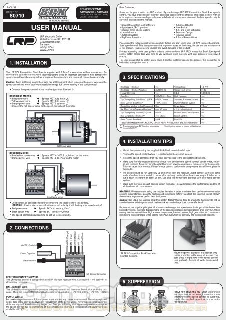
The LRP <strong>SPX</strong> <strong>Competition</strong> <strong>StockSpec</strong> is supplied with 2.6mm² power-wires without connectors. Be<br />
very careful with the correct wire sequence/colors since an incorrect connection may damage the<br />
speed-control! Avoid creating solder bridges on the solder-tabs and isolate all connections carefully.<br />
Caution: Avoid soldering longer then 5sec per soldering joint when replacing the power wires on the<br />
speed-control and motor to prevent possible damage due to overheating of the <strong>com</strong>ponents!<br />
• Connect the speed-control to the receiver (position: Channel 2)<br />
BRUSHLESS MOTOR:<br />
• Blue power-wire Speedo MOT.A to motor „A“<br />
• Yellow power-wire Speedo MOT.B to motor „B“<br />
• Orange power-wire Speedo MOT.C to motor „C“<br />
• Connect the hall sensor cable to the speed-control and the motor.<br />
C + B -<br />
C + B -<br />
A<br />
A<br />
blue<br />
yellow<br />
blue<br />
Hall Sensor Wire<br />
BRUSHED MOTOR:<br />
• Blue/Yellow power-wire Speedo MOT.A/MOT.B to „Minus“ on the motor.<br />
• Orange power-wire Speedo MOT.C to „Plus“ on the motor.<br />
orange<br />
together to minus<br />
• Doublecheck all connections before connecting the speed-control to a battery.<br />
CAUTION: If battery is connected with reversed polarity it will destroy your speed-control!<br />
• Red power-wire Speedo BAT+ to battery „Plus“<br />
• Black power-wire Speedo BAT- to battery „Minus“<br />
• The speed-control is now ready to be set-up (see section 6).<br />
+<br />
-<br />
yellow<br />
orange<br />
C<br />
B<br />
A<br />
3. specifications<br />
Brushless + Brushed yes Voltage Input 4.8-7.4V<br />
Brushless + Brushed Adaption AUTOMATIC Weight (excl. wires) 24.5g<br />
Forward/Reverse yes B.E.C. 6.0V/3.0A<br />
Case Size 33.1x37.6x14.9mm High Frequency yes<br />
Typ. Voltage Drop (Brushless)* @20A 0.013V / phase Sensored Brushless System yes<br />
Rated Current (Brushless)* 400A / phase Multi-Protection-System yes<br />
Compatible winding styles (Brushless) Star Power Wires 2.6mm²<br />
Rec. Motor Limit for Star winds (Brushless)** over 3.5 turns 4, 5, 6 cell optimised yes<br />
Typ. Voltage Drop (Brushed)* @20A 0.010V Internal-Temp-Check System yes<br />
Rec. Motor Limit (Brushed)** over 5 turns Launch Control yes<br />
Rated Current (Brushed)* 400A Blue LED yes<br />
4 adjustable Modes (NiMH/LiPo, ADPC/DEMS Power Profiles, Initial- and Automaticbrake) yes<br />
* Transistors rating at 25°C junction temperature Specifications subject to change without notice.<br />
** measured at 7.2V<br />
4. installation tips<br />
• Mount the speedo using the supplied thick/black doubled-sided tape.<br />
• Position the speed-control where it is protected in the event of a crash.<br />
• Install the speed-control so that you have easy access to the connector and buttons.<br />
• Make sure there is enough clearance (about 3cm) between the speed-control, power-wires, antenna<br />
and receiver. Avoid any direct contact between power <strong>com</strong>ponents, the receiver or the antenna.<br />
This can cause interference. If interference occurs, position the <strong>com</strong>ponents at a different place in<br />
the model.<br />
• The aerial should be run vertically up and away from the receiver. Avoid contact with any parts<br />
made of carbon fibre or metal. If the aerial is too long, don’t coil up the excess length. It is better to<br />
cut it down to a length of about 35 cm. See also the instructions supplied with your radio control<br />
system.<br />
• Make sure there are enough cooling slits in the body. This will increase the performance and life of<br />
all the electronic <strong>com</strong>ponents.<br />
HEATSINK: We re<strong>com</strong>mend using the supplied heatsink in order to achieve best performance even under<br />
extreme circumstances. Clean the heatsink and stickerplate before you attach the clear/thin Scotch 468MP<br />
thermal tape to guarantee perfect heat dissipation.<br />
Caution: Use ONLY the supplied clear/thin Scotch 468MP thermal tape to attach the heatsink! Do not us<br />
standard double sided tape to attach the heatsink as standard tape does not transfer heat!<br />
Because of the physical principles of brushless technology, the speed-controls do get a little hotter then<br />
brushed systems. Therefore it is required to let the speed-control cool down <strong>com</strong>pletely after every run. When<br />
running in extreme conditions (high ambient temperature, low-turn motors, high gear ratios, etc.) we re<strong>com</strong>mend<br />
using the optional pre-wired cooling fan (#82500) which fits perfectly into the supplied heatsink.<br />
2. connections<br />
On/Off - Switch<br />
MOT.C (Orange)<br />
BAT + (Red)<br />
MOT.B (Yellow)<br />
BAT - (Black)<br />
MOT.A (Blue)<br />
Power Capacitor<br />
Receiverwire<br />
LRP <strong>SPX</strong> <strong>Competition</strong> <strong>StockSpec</strong> with<br />
mounted heatsink.<br />
Mount the power-capacitor in a position where<br />
it is protected in the event of a crash. The<br />
best place is right next to the speed-control<br />
(see picture). Secure it with doublesided<br />
tape.<br />
Hall Sensor Connector<br />
RECEIVER CONNECTING WIRE:<br />
This LRP speed-control is equipped with an LRP Multicon receiver wire. As supplied, it will easily fit in<br />
all ordinary receivers.<br />
HALL SENSOR WIRE:<br />
This bi-directional multipole wire connects the speed-control and the motor. Do not alter or modify this<br />
cable! There are replaceable/optional hall sensor wires available: • #81910 (20cm) • #81920 (10cm)<br />
POWER WIRES:<br />
For maximum performance, 2.6mm² power wires without any connectors are used. The unique splitted<br />
solder-tabs allow easy and convenient replacement of the power wires. Nevertheless some soldering<br />
skills are required. Avoid soldering longer then 5sec per soldering joint to prevent possible damage to<br />
the speed-control due to overheating of the <strong>com</strong>ponents! There is a full replacement power wire set<br />
available: #82505<br />
5. suppression<br />
ONLY FOR BRUSHED MOTORS! Motors with<br />
no capacitors or not enough capacitors may<br />
interfere with the speed-control. To avoid this,<br />
solder the supplied capacitors to your motor<br />
(see picture).
6. radio / speed-control set-up<br />
In setup mode the LRP <strong>SPX</strong> <strong>Competition</strong> <strong>StockSpec</strong> stores every step when you press the SET button. All<br />
the settings will be stored in the speed-controls memory even if the speed-control will be disconnected from<br />
the battery.<br />
TRANSMITTER SETTINGS<br />
Setup the following basic functions on your transmitter (if available):<br />
Throttle travel High ATV, EPA maximum<br />
Brake travel Low ATV, EPA, ATL maximum<br />
Throttle exponential EXP, EXPO start with 0<br />
Neutral trim SUB Trim centre<br />
Servo reverse Throttle reverse any setting, don‘t change after set-up procedure!<br />
If your transmitter doesn‘t offer any of above functions, it‘s already in „basic setup“ mode.<br />
• Ensure that the speed-control is not connected to the drive battery and is switched off.<br />
• Remove motor pinion or ensure that the wheels of the model are free to rotate.<br />
• Switch the transmitter on and set the transmitter throttle stick to neutral.<br />
• Connect the speed-control to the battery, and switch the unit on.<br />
• Hold the SET button pressed for at least 3sec using the supplied plastic screwdriver.<br />
You entered setup mode and the SET LED flashes blue (it will flash until the setup is <strong>com</strong>pleted).<br />
• Leave transmitter in neutral position and press the SET button once.<br />
Neutral setting is stored , MODE LED flashes yellow and the motor beeps.<br />
• Hold full throttle on transmitter and press the SET button once.<br />
Full-throttle setting is stored, MODE LED flashes red.<br />
• Hold full brake on transmitter and press the SET button once.<br />
Brake setting is stored, LED‘s glow red (MODE) and blue (SET).<br />
• This <strong>com</strong>pletes the setup procedure and your LRP <strong>SPX</strong> <strong>Competition</strong> <strong>StockSpec</strong> is ready to use.<br />
• If you make a mistake during the setup procedure, don‘t worry: Disconnect the battery for about 10sec and<br />
start again from the first step.<br />
• At the end of each run switch of the car, and then switch off the transmitter.<br />
• At the start of each run switch on the transmitter first, then switch on the car.<br />
• For storage of the car, disconnect the drive battery at any time!<br />
CHECKING THE FUNCTIONS:<br />
Check the LED‘s when moving your throttle stick and you will see if everything is setup correctly.<br />
FUNCTION STATUS MODE LED SET LED<br />
Neutral (automatic brake inactive) -- off blue<br />
Neutral (automatic brake active) -- red off<br />
Forward partial throttle yellow off<br />
Forward full throttle yellow blue<br />
Brake partial brake red off<br />
Brake full brake red blue<br />
8. special Features<br />
Internal-Temp-Check System: the LRP <strong>SPX</strong> <strong>Competition</strong> <strong>StockSpec</strong> allows you to read-out the maximum<br />
internal temperature that the speedo reached. To store it to the memory, briefly apply brakes after the run before you<br />
turn the switch off. You can convienently read-out the temperature back in the pits since it remains stored until you<br />
turn it on the next time regularly (which will reset the memory). This new feature allows you to accurately check if all<br />
is running well or if you‘re close to shutdown already.<br />
How to read-out the temperature:<br />
Switch at „OFF“ position.<br />
Keep MODE button pressed while you turn switch to „ON“ (then release button)<br />
SET LED will start to flash blur (MODE LED is off), now count the number of flashes.<br />
Basics:<br />
• Thermal shutdown of the speedo would occur at 5 flashes.<br />
• The higher the number of flashes, the cooler the speedo ran (e.g. the better it is!)<br />
• Every flash equals to ~8°C temperature decrease<br />
Example:<br />
you count 10 flashes after the run<br />
10 - 5 = 5 (e.g. 5 flashes „away“ from shutdown)<br />
5 x 8°C = 40°C (e.g. you are 40°C away from thermal shutdown and therefore safe!)<br />
Launch Control: the launch control allows „rocket like“ starts. After activation it gives you more power one time<br />
for the start (this feature is only re<strong>com</strong>mended to be used with touring cars on high traction surfaces!).<br />
Activate launch control Hold trigger on radio at full brake for 5sec before start. Ready and active!!!<br />
AutoCell System: Ready for the next battery technology – LiPo batteries! LRP’s exclusive and smart AutoCell<br />
System ensures that LiPo batteries can be used safely without accidentially deep-discharging of the cells. The motor<br />
function will be shut-off and the SET LED will flash if the system recognises very low battery voltage.<br />
ADPC Brushless - Power Profiles: results in more power and better driveability. Depending on the<br />
status of the car (start, acceleration, full speed) the software calculates the perfect motor management. Higher value<br />
means more overall power and aggressive response.<br />
Caution: Do not advance mechanical timing on the motor when using high ADPC profiles!<br />
D.E.M.S. Brushed - Power Profiles: The known and world‘s winning D.E.M.S. Brushed Quantum style<br />
power programs have been implemented into the LRP <strong>SPX</strong> <strong>Competition</strong> <strong>StockSpec</strong> as well. Higher value means more<br />
overall power and aggressive response.<br />
Automatic Brushless / Brushed Adaption: The LRP exclusive Automatic Brushless/Brushed Adaptation<br />
detects the connected motor type during turn-on/initialisation and adjusts the correct brushless or brushed<br />
operation automatically. No adjustments required by yourself, apart from the correct connection of each motor type<br />
(don‘t forget the hall-sensor-wire for brushless!).<br />
Caution: Keep in mind, when swopping between brushless and brushed motors, that the chosen mode values will<br />
be identical!<br />
Changing Mode settings without the transmitter: At race events you usually do not have access<br />
to your transmitter, but never mind since you can simply disconnect the receiver lead from the receiver and change<br />
the MODE settings as described in section 7 „Mode Programming“.<br />
Works-Default-Settings: All LRP speed-controls <strong>com</strong>e factory-adjusted (defaults are grey-shaded above). If<br />
you loose track of the modes, you can restore the works default settings. With the transmitter switched on, hold the<br />
SET button pressed while you switch on the speed-control. This returns the unit to the LRP works default settings.<br />
Power Capacitor: Never disconnect the power-capacitor! It offers increased punch and additional protection.<br />
IceDrive Design: LRP’s secret IceDrive Design results in lower speedo temperature under all racing conditions<br />
and for both brushless + brushed. Sorry, no further details to be disclosed. Simply a step ahead of the <strong>com</strong>petition!<br />
Forward/Brake: Un<strong>com</strong>promising and outstanding performance for top level <strong>com</strong>petition was the target! Therefore<br />
the LRP engineering team developed a pure forward/brake <strong>com</strong>petition speed-control without reverse function.<br />
Sensored Brushless Technology: Advanced Digital allows the perfect knowledge of the brushless motor’s<br />
magnet position. This results in perfect motor control at high and low RPM‘s, as well as perfect brake control.<br />
Multi-Protection System, 3-way protection: The perfect protection against short-circuits (motor),<br />
overload and overheating. If your speed-control faces overload, the motor function will be shut-off for protection<br />
and the SET LED will flash, although the steering function is maintained. Let the speed-control cool down for a few<br />
minutes. If you experience frequent shutdowns, check for the following:<br />
• Correct gear ratio (refer to motor manual for gearing re<strong>com</strong>mendations)<br />
• ADPC setting too high (higher value will heat up motor and speed-control excessively)<br />
• Motor is too strong or motor is damaged.<br />
7. mode programming<br />
All modes are available for brushless and brushed motors (speedo adapts automatically). The LRP <strong>SPX</strong> <strong>Competition</strong><br />
<strong>StockSpec</strong> features 4 modes which enable you to adjust it to YOUR special requirements. The factory<br />
settings are shown in grey colour.<br />
• How to get into „programming the modes“ Press MODE button for 3 or more seconds.<br />
• How to check the stored values<br />
Count the number of flashes of the blue SET-LED<br />
(1x = value 1, 2x = value 2, etc.).<br />
• How to change the value<br />
Press SET button to increase value by one step.<br />
• How to get to the next Mode<br />
Press MODE button once.<br />
• How to leave the programming mode If you are in MODE.4, press the MODE button<br />
one more time<br />
• Table of settings, values and modes: see below (grey-shaded values show „works default settings“).<br />
MODE.1 (AutoCell System):<br />
we re<strong>com</strong>mend using value 2 for 4-6 cells NiMH racing purposes, which disengages the LiPo protection.<br />
MODE LED Value 1 Value 2<br />
Yellow<br />
LiPo/NiMH<br />
Automatic<br />
4-6cell NiMH<br />
Racing Mode<br />
MODE.2 (ADPC Brushless Power Profiles): only with connected Brushless motor<br />
allows you to adjust the <strong>SPX</strong> <strong>Competition</strong> <strong>StockSpec</strong> to your likes. Either you run on stock or modified motors or<br />
on slippery or high-traction surfaces, we have incorporated a profile for you!<br />
Higher value means more overall power and more aggressive throttle response.<br />
MODE LED Value 1 Value 2 Value 3 Value 4 Value 5 Value 6 Value 7 Value 8<br />
smooth smooth smooth Linear Linear+ Agressive agressive+ Agressive++<br />
Red<br />
Power: 1X Power: 2X Power: 3X Power: 4X Power: 6X Power 6X Power 7X Power 7X<br />
Modified Motor (4.0 to 8.5t) Power Profiles<br />
Stock Motor (8.5 - 21.5t) Power Profiles<br />
MODE.2 (DEMS Brushed Power Profiles): only with connected Brushed motor<br />
Higher value means more overall power and more aggressive throttle response.<br />
MODE LED Value 1 Value 2 Value 3 Value 4 Value 5 Value 6<br />
Red<br />
smooth,<br />
low traction<br />
very<br />
linear<br />
linear, punch<br />
increasing<br />
aggressive<br />
profile<br />
very aggressive<br />
profile<br />
super aggressive<br />
profile<br />
MODE.3 (Initial Brake): Allows you to set a certain level of „hand-brake-effect“.<br />
MODE LED Value 0 Value 1 Value 2 Value 3 Value 4 Value 5 Value 6<br />
Yellow/Red<br />
(alternate)<br />
Team Tips: A good starting point for the brake setting on your radio is 80% (bonded) and 70% (sintered) for all<br />
classes. Make sure you do the radio-setup with all settings on the radio on 100%.<br />
MODE.4 (Automatic Brake): allows you to set a slight braking action which is applied in the neutral<br />
range. This enables you to simulate the feel of a brushed motor and also hold the throttle on longer when entering<br />
a turn. For brushless motors you achieve the same natural slowdown as a brushed motor with no autobrake<br />
when you set value 1-2 (for motors with bonded magnets) or 0-1 (for motors with sintered magnets).<br />
MODE LED Value 0 Value 1 Value 2 Value 3 Value 4 Value 5 Value 6<br />
Yellow/Red<br />
(same time)<br />
No Initial<br />
Brake<br />
No Automatic<br />
Brake<br />
Going from lowest to highest inital brake setting<br />
(value 1 = minimum / value 6 = maximum)<br />
Going from lowest to highest automatic brake setting<br />
(value 1 = minimum / value 6 = maximum)<br />
9. troubleshooting guide<br />
EXPLANATION: If no remark, cause can be either with brushless or brushed motor. If „BM“ is indicated,<br />
cause only relating to brushed motor.<br />
Symptom Cause Remedy<br />
Servo is working, no motor function. Speed-control plugged in incorrectly Plug speed-control in Ch 2<br />
Overload protection activated<br />
Wiring problem<br />
Motor defective<br />
BM - Motor brushes stuck<br />
Speed-control defective<br />
Allow speed-control to cool down<br />
Check wires and plugs<br />
Replace motor<br />
Check that brushes are moving freely<br />
Send in product for repair<br />
No servo and no motor function. Speed-control plugged in incorrectly Plug speed-control in with correct polarity<br />
Motor runs in reverse when accelerating<br />
forward on the transmitter.<br />
Insufficient performance.<br />
E.g. poor brake power, topspeed or<br />
acceleration..<br />
Crystal defective<br />
Receiver defective<br />
Transmitter defective<br />
Speed-control defective<br />
BM - Motor connected incorrectly<br />
Replace <strong>com</strong>ponents one by one.<br />
Send in product for repair<br />
Connect motor correctly<br />
Motor pinion too big or gear ratio too long. Use smaller motor pinion/shorter gear ratio<br />
Transmitter settings changed after set-up Repeat set-up procedure<br />
BM - Motor worn out<br />
Maintain motor<br />
Motor defective<br />
Replace motor<br />
Speed-control defective.<br />
Send in product for repair<br />
Speed-control overheats or switches<br />
off frequently.<br />
Motor stronger than motorlimit or input voltage<br />
too high<br />
Use only motors and batteries which are within<br />
the specifications of the speed-control<br />
Motor pinion too big or gear ratio too long. Use smaller motor pinion/shorter gear ratio<br />
Drive train or bearing problems.<br />
Check or replace <strong>com</strong>ponents.<br />
Model used too often without cool-down periods Let speed-control cool down after every run<br />
Motor never stops, runs at constant Transmitter settings changed after set-up Repeat set-up procedure<br />
slow speed<br />
Humidity/water in speed-control<br />
Immediately unplug and dry speed-control<br />
Speed-control defective<br />
Send in product for repair<br />
Radio interference BM - Motor suppressors not sufficient Solder capacitors to motor<br />
Receiver or antenna too close to power wires,<br />
motor, battery or speed-control.<br />
Receiver aerial too short or coiled up<br />
See „Installation Tips“ and „Installation“<br />
Receiver defective, too sensitive;<br />
Transmitter defective, transmitter output power<br />
too low, servo problem<br />
Poor battery connection<br />
Transmitter batteries empty<br />
Transmitter antenna too short<br />
Replace <strong>com</strong>ponents one by one<br />
Only use original manufacturers crystals<br />
Check plugs and connecting wires<br />
Replace / recharge transmitter batteries<br />
Pull out antenna to full length
!<br />
warning notes<br />
RA00263<br />
!<br />
warnhinweise<br />
No toy. Not suitable for children under 14 years.<br />
Keep the product out of the reach of children.<br />
Pay close attention to the following points, as they can destroy<br />
the product and void your warranty.Non-observance<br />
of these points can lead to property damage, personal and<br />
severe injuries!<br />
• Never leave the product unsupervised while it is switched<br />
on, in use or connected with a power source. If a defect occurs,<br />
it could set fire to the product or the surroundings.<br />
• Never wrap your product in plastic film, metal foil or similar.<br />
In fact, make sure it gets enough fresh air.<br />
• Avoid incorrect connections or connections with reversed<br />
polarity of the product.<br />
• All wires and connections have to be well insulated. Shortcircuits<br />
can possibly destroy the product.<br />
• Never allow this product or other electronic <strong>com</strong>ponents to<br />
<strong>com</strong>e in contact with water, oil or fuels or other electroconductive<br />
liquids, as these could contain minerals, which are<br />
harmful for electronic circuits. If this happens, stop the use<br />
of your product immediately and let it dry carefully.<br />
• Never cut off or modify the original plugs and original wires.<br />
• Never open the product and never solder on the PCB or other<br />
<strong>com</strong>ponents.<br />
• Never use this product when the case is open, damaged or<br />
missing or when the product is wrapped in a shrink-fit tube.<br />
This will reduce protection, may cause short circuits and<br />
damage the product.<br />
• Always remove the battery from your product or disconnect<br />
the product from the power source, if the product is not in<br />
use.<br />
• Always switch on your transmitter first before you switch on<br />
the receiver or the speed control. The receiver could receive<br />
interference signals, start full acceleration and damage your<br />
model. When you switch off, make sure you do so in the reverse sequence. First switch off the receiver and<br />
speed control, then switch off the transmitter.<br />
• Never apply full throttle if the motor is not installed. Due to the extremely high RPMs without load, the<br />
motor can get damaged.<br />
• Never solder a Schottky diode to the motor when you are using this speed-control.<br />
• If the speed-control is connected to the motor, never run the motor directly with a separate battery or run-in<br />
device.<br />
• Never change the polarity of the receiver connector.<br />
• Always wire up all the parts of the equipment carefully. If any of the connections <strong>com</strong>e loose as a result of<br />
vibration, you could loose control over your model.<br />
• Avoid soldering longer then 5 seconds per soldering joint when replacing the power wires to prevent possible<br />
damage to the product due to overheating of the <strong>com</strong>ponents. Use a high power soldering station with<br />
at least 60W for soldering.<br />
The manufacturer can not be held responsible for damages, which are a result of non-observance of the<br />
warning notes and security advices.<br />
Kein Spielzeug. Nicht für Kinder unter 14 Jahren geeignet.<br />
Bewahren Sie das Produkt außerhalb der Reichweite von kleinen<br />
Kindern auf.<br />
Beachten Sie unbedingt die folgenden Hinweise, da diese Ihr<br />
Produkt zerstören können und die Gewährleistung ausschließen.<br />
Nichtbeachtung dieser Hinweise können zu Sach- und<br />
Personenschäden und schweren Verletzungen führen!<br />
• Nassen Sie das Produkt niemals unbeaufsichtigt, solange es<br />
eingeschaltet, in Betrieb oder mit einer Stromquelle verbunden<br />
ist. Im Falle eines Defekts könnte dies Feuer am Produkt<br />
oder seiner Umgebung verursachen.<br />
• Wickeln Sie Ihr Produkt niemals mit Plastikfolie, Metallfolie<br />
oder Ähnlichem ein, sondern sorgen Sie im Gegenteil für<br />
Frischluft.<br />
• Vermeiden Sie falschen Anschluss oder Verpolung des Produkts.<br />
• Alle Kabel und Verbindungen müssen gut isoliert sein. Kurzschlüsse<br />
können unter Umständen das Produkt zerstören.<br />
• Dieses Produkt oder andere elektronische Komponenten<br />
dürfen niemals mit Wasser, Öl, Treibstoffen oder anderen<br />
elektrisch leitenden Flüssigkeiten in Berührung kommen, da<br />
diese Mineralien enthalten können, die elektronische Schaltkreise<br />
korrodieren lassen. Bei Kontakt mit diesen Stoffen<br />
müssen Sie sofort den Betrieb einstellen und das Produkt<br />
sorgfältig trocknen.<br />
• Die Originalstecker und Originalkabel dürfen niemals verändert<br />
oder abgeschnitten werden.<br />
• Öffnen Sie niemals das Produkt und löten Sie keinesfalls auf<br />
der Platine oder anderen Komponenten<br />
• Benutzen Sie Ihr Produkt nicht mit geöffnetem, beschädigtem<br />
oder fehlendem Gehäuse oder in Schrumpfschlauch.<br />
Dies mindert den Störschutz, kann Kurzschlüsse verursachen<br />
und das Produkt beschädigen.<br />
• Entnehmen Sie immer den Akku aus Ihrem Produkt bzw. trennen Sie das Produkt von der Stromquelle, wenn<br />
das Produkt nicht verwendet wird.<br />
• Schalten Sie immer zuerst Ihren Sender ein, bevor Sie den Empfänger oder Fahrtenregler einschalten. Der<br />
Empfänger könnte Störsignale auffangen, Vollgas geben, und Ihr Modell beschädigen. Beim Ausschalten<br />
beachten Sie die umgekehrte Reihenfolge. Erst Empfänger und Fahrtenregler ausschalten, dann Sender<br />
ausschalten.<br />
• Geben Sie keinesfalls Vollgas, wenn der Motor noch nicht eingebaut ist. Durch die extrem hohen<br />
Drehzahlen ohne Last kann der Motor beschädigt werden.<br />
• Löten Sie bei Verwendung dieses Reglers niemals eine Schottky-Diode an den Motor.<br />
• Solange der Motor an den Regler angeschlossen ist, dürfen Sie niemals den Motor mit einem separaten<br />
Akku oder mit einem Motor-Einlaufgerät laufen lassen.<br />
• Stellen Sie sicher, dass die Kühlbleche der Fets sich niemals berühren - Kurzschlußgefahr!<br />
• Verändern Sie niemals die Polarität des Empfängersteckers.<br />
• Schließen Sie sämtliche Teile der Ausrüstung sorgfältig an. Falls sich die Verbindungen durch Vibrationen<br />
lösen, können Sie die Kontrolle über das Modell verlieren.<br />
• Vermeiden Sie es beim Wechseln der Powerkabel länger als 5 Sekunden je Lötstelle zu löten, um eine Beschädigung<br />
der Bauteile durch Überhitzung auszuschließen. Verwenden Sie zum Löten eine leistungsstarke<br />
Lötstation mit mind. 60W.<br />
Der Hersteller kann nicht für Schäden verantwortlich gemacht werden, die infolge von Nichtbeachtung<br />
der Sicherheitshinweise und Warnungen verursacht werden.<br />
The crossed-out wheeled bin means that within the European Union the product must be<br />
taken to seperate collection at the product end-of-life. Do not dispose of these products as<br />
unsorted municipal waste.<br />
Das Symbol einer durchgestrichenen Abfalltonne auf Rädern bedeutet, dass das Produkt in<br />
der Europäischen Union einer getrennten Müllsammlung zugeführt werden muss. Diese Produkte<br />
dürfen nicht über den unsortierten Hausmüll entsorgt werden.<br />
repair procedures / limited warranty<br />
All products from LRP electronic GmbH (hereinafter called “LRP”) are manufactured according to the highest<br />
quality standards. LRP guarantees this product to be free from defects in materials or workmanship for 90<br />
days (non-european countris only) from the original date of purchase verified by sales receipt. This limited<br />
warranty doesn’t cover defects, which are a result of misuse, improper maintenance, outside interference or<br />
mechanical damage.<br />
„This applies among other things on:<br />
• Cut off original power plug or not using reverse polarity protected plugs<br />
• Receiver wire and/or switch wire damaged<br />
• Mechanical damage of the case<br />
• Humidity/Water inside the speed control<br />
• Mechanical damage of electronical <strong>com</strong>ponents/PCB<br />
• Soldered on the PCB (except on external solder-tabs)<br />
• Connected speed-control with reversed polarity“<br />
To eliminate all other possibilities or improper handling, first check all other <strong>com</strong>ponents in your model and the<br />
trouble shooting guide, if available, before you send in this product for repair. If products are sent in for repair,<br />
which do operate perfectly, we have to charge a service fee according to our pricelist.<br />
With sending in this product, the customer has to advise LRP if the product should be repaired in either case. If<br />
there is neither a warranty nor guarantee claim, the inspection of the product and the repairs, if necessary, in<br />
either case will be charged with a fee at the customers expense according to our price list. A proof of purchase<br />
including date of purchase needs to be included. Otherwise, no warranty can be granted. For quick repair- and<br />
return service, add your address and detailed description of the malfunction.<br />
If LRP no longer manufactures a returned defective product and we are unable to service it, we shall provide you<br />
with a product that has at least the same value from one of the successor series.<br />
The specifications like weight, size and others should be seen as guide values. Due to ongoing technical improvements,<br />
which are done in the interest of the product, LRP does not take any responsibility for the accuracy<br />
of these specs.<br />
LRP-Distributor-Service:<br />
• Package your product carefully and include sales receipt and detailed description of malfunction.<br />
• Send parcel to your national LRP distributor.<br />
• Distributor repairs or exchanges the product.<br />
• Shipment back to you usually by COD (cash on delivery), but this is subject to your national LRP distributor‘s<br />
general policy.<br />
ALLGEMEINE GEWÄHRLEISTUNGS- UND<br />
REPARATURBESTIMMUNGEN<br />
Produkte der LRP electronic GmbH (nachfolgend „LRP“ genannt) werden nach strengsten Qualitätskriterien<br />
gefertigt. Wir gewähren die gesetzliche Gewährleistung auf Produktions- und Materialfehler, die zum Zeitpunkt<br />
der Auslieferung des Produkts vorhanden waren. Für gebrauchstypische Verschleißerscheinungen wird nicht<br />
gehaftet. Diese Gewährleistung gilt nicht für Mängel, die auf eine unsachgemäße Benutzung, mangelnde Wartung,<br />
Fremdeingriff oder mechanische Beschädigung zurückzuführen sind.<br />
„Dies liegt unter Anderem vor bei:<br />
• Stecker abgeschnitten bzw. kein verpolsicheres Stecksystem<br />
• Empfängerkabel und/oder Schalter beschädigt<br />
• Gehäuse mechanisch beschädigt<br />
• Wasser/Wasserrückstände im Gehäuse<br />
• Mechanische Beschädigung der Bauteile/Platine<br />
• Auf der Platine gelötet (Ausnahme außen liegende Lötlaschen)<br />
• Akkuseitig verpolt“<br />
Bevor Sie dieses Produkt zur Reparatur einsenden, prüfen Sie bitte zunächst alle anderen Komponenten in ihrem<br />
Modell und schauen Sie ggf. in der Fehlerfibel des Produktes (sofern vorhanden) nach, um andere Störquellen<br />
und Bedienfehler auszuschließen. Sollte das Produkt bei der Überprüfung durch unsere Serviceabteilung<br />
keine Fehlfunktion aufweisen, müssen wir Ihnen hierfür die angefallenen Bearbeitungskosten laut Preisliste<br />
berechnen.<br />
Mit der Einsendung des Produktes muss der Kunde mitteilen, ob das Produkt in jedem Fall repariert werden<br />
soll. Sollte kein Gewährleistungs- oder Garantieanspruch bestehen, erfolgt die Produktüberprüfung und ggf.<br />
Reparatur in jedem Falle kostenpflichtig gemäß unserer Preisliste. Ein Gewährleistungs- oder Garantieanspruch<br />
kann nur anerkannt werden, sofern eine Kopie des Kaufbelegs beigefügt ist. Auf Ihre ausdrückliche Anforderung<br />
erstellen wir einen kostenpflichtigen Kostenvoranschlag. Wenn Sie nach Zusendung des Kostenvoranschlags<br />
den Auftrag zur Reparatur erteilen, entfallen die Kostenvoranschlagskosten. An unseren Kostenvoranschlag<br />
sind wir zwei Wochen ab Ausstellungsdatum gebunden. Für eine schnelle Abwicklung Ihres Servicefalls legen<br />
Sie bitte eine ausführliche Fehlerbeschreibung und ihre Adressdaten der Einsendung bei.<br />
Falls ein zurückgesandtes, defektes Produkt von LRP nicht mehr produziert wird, und wir dieses nicht reparieren<br />
können, so erhalten Sie statt dessen ein mindestens gleichwertiges Produkt aus einer der Nachfolgeserien.<br />
Die von LRP angegebenen Werte über Gewicht, Größe oder Sonstiges sind als Richtwert zu verstehen. LRP<br />
übernimmt keine formelle Verpflichtung für derartige spezifische Angaben, da sich durch technische Veränderungen,<br />
die im Interesse des Produkts vorgenommen werden, andere Werte ergeben können.<br />
LRP-Werks-Service:<br />
• Produkt mit Kaufbeleg und Fehlerbeschreibung bruchsicher verpacken.<br />
• Einsenden an:<br />
LRP electronic GmbH – Serviceabteilung<br />
Wilhelm-Enssle-Str. 132-134, 73630 Remshalden, Deutschland<br />
Technik + Service Hotline: D: 0900 577 4624 (0900 LRP GMBH) (0.49€/Minute aus dem dt. Festnetz. Mobilfunkpreise können abweichen)<br />
A: 0900 270 313 (0.73€/Minute aus dem öst. Festnetz. Mobilfunkpreise können abweichen)<br />
eMail: service@lrp-electronic.de<br />
Web: www.lrp.cc<br />
• LRP repariert das Produkt.<br />
• Rücksendung an Sie per Nachnahme.