narrow rocking curve multilayer x-ray mirrors - ICDD
narrow rocking curve multilayer x-ray mirrors - ICDD
narrow rocking curve multilayer x-ray mirrors - ICDD

Create successful ePaper yourself
Turn your PDF publications into a flip-book with our unique Google optimized e-Paper software.
Copyright(c)JCPDS-International Centre for Diffraction Data 2000,Advances in X-<strong>ray</strong> Analysis,Vol.43 223<br />
NARROW ROCKING CURVE MULTILAYER X-RAY MIRRORS<br />
S. M. Owens ∗<br />
Laboratory for High Energy Astrophysics, Goddard Space Flight Center, NASA,<br />
Greenbelt, MD<br />
R. D. Deslattes<br />
Atomic Physics Division, National Institute of Standards and Technology,<br />
Gaithersburg, MD<br />
J. Pedulla<br />
J. Pedulla Associates, Silver Spring, MD<br />
Abstract<br />
Over the past few years <strong>multilayer</strong> x-<strong>ray</strong> optics, or <strong>mirrors</strong>, have become a commercially<br />
viable product for the manipulation of hard x-<strong>ray</strong>s (~8 keV). Multilayer design has<br />
typically been along the following formula: choose a pair of stable materials with high<br />
electron density contrast; investigate their chemical compatibility for thin film deposition;<br />
investigate the interface characteristics of the bilayer system; optimize deposition<br />
parameters to provide a stable and repeatable yield. A few material combinations have<br />
been found to produce high quality <strong>mirrors</strong>, including but not limited to W/Si, Mo/Si, and<br />
Ni/C. The use of such high contrast pairs necessarily yields wide <strong>rocking</strong> <strong>curve</strong>s<br />
compared to perfect crystal analyzers. If one manufactures <strong>multilayer</strong> <strong>mirrors</strong> from two<br />
low-density materials, or ultimately, alternating densities of the same element or<br />
material, the <strong>rocking</strong> <strong>curve</strong> of the Bragg peak can be directly engineered to tailor the<br />
angular divergence of the beam to the specific application.<br />
Introduction<br />
By artificially growing a large number of thin layers of alternating density with periodic<br />
thickness one can simulate the reflecting effects of a one-dimensional crystal, but with a<br />
less stringent reflection range than perfect crystal optics. Such structures, called<br />
<strong>multilayer</strong> x-<strong>ray</strong> <strong>mirrors</strong>, have become a standard component in the toolbox for the design<br />
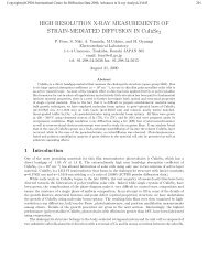
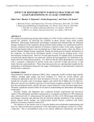
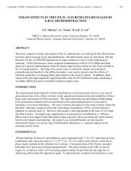
of x-<strong>ray</strong> analysis equipment. The reflectivity as a function of angle of a Pt/C <strong>multilayer</strong><br />
mirror is shown in Figure 1. Like crystal optics, though, <strong>multilayer</strong>s have their own<br />
limitations, some of which arise due to the choice of materials with high electron density<br />
contrast.<br />
One of the major differences in operation between <strong>multilayer</strong>s and perfect crystals is the<br />
<strong>rocking</strong> <strong>curve</strong> of reflection, or the angular range over which x-<strong>ray</strong>s are efficiently<br />
reflected through the optic. Multilayers have <strong>rocking</strong> <strong>curve</strong>s on the order of 100 to 225<br />
arcseconds (0.03 to 0.06 degrees), while the widest perfect crystal reflection commonly<br />
used is the Ge(111) reflection, which has a <strong>rocking</strong> <strong>curve</strong> of 16 arcseconds. Thus, there is<br />
currently a wide gap between the widest perfect crystal reflectors and the <strong>narrow</strong>est<br />
<strong>multilayer</strong> <strong>mirrors</strong> that deserves to be addressed.<br />
∗ This work performed as a National Research Council Postdoctoral Research Associate at the National<br />
Institute of Standards and Technology, Gaithersburg, MD
Copyright(c)JCPDS-International Centre for Diffraction Data 2000,Advances in X-<strong>ray</strong> Analysis,Vol.43 224<br />
1<br />
Simulation of a 30(Pt/C) Multilayer<br />
0.1<br />
Reflectivity<br />
0.01<br />
0.001<br />
0.0001<br />
10 -5<br />
0 0.5 1 1.5 2 2.5<br />
Grazing Angle (deg)<br />
Figure 1. Simulated reflectivity of a 30 bilayer Pt/C <strong>multilayer</strong> mirror for 8 keV (Cu Kα 1 ) x-<strong>ray</strong>s. The<br />
FWHM of the peak at 1.16 degrees is 0.063 degrees or 225 arcseconds.<br />
Multilayer Basics<br />
A <strong>multilayer</strong> mirror is typically comprised of a number (25 – 100) of bilayers of materials<br />
like W/Si, Mo/Si, or Ni/C. Historically, the high-density material is termed the<br />
“reflector”, and the low-density material the “spacer”, even though scattering occurs at<br />
the interface between materials, and not in the materials themselves. This misnomer may<br />
lead one to assume that high-density reflector and low-density spacer materials are<br />
necessary to achieve high performance. While this is not entirely true, the choice of high<br />
electron density contrast means that a large amount of radiation is scattered at each<br />
interface, and the maximum possible reflectivity is achieved with relatively few bilayers.<br />
If only a small number of interfaces contribute to the reflection the <strong>rocking</strong> <strong>curve</strong> is<br />
relatively wide, according to standard diffraction theory.<br />
By designing a <strong>multilayer</strong> mirror using a pair of materials with lower contrast, less<br />
radiation is scattered at each interface, more interfaces can contribute to the reflection<br />
process and a <strong>narrow</strong>er <strong>rocking</strong> <strong>curve</strong> is the result. Taken to the limit, controlling the<br />
density of alternating layers of a single element or material allows one to directly<br />
engineer the reflectivity at each interface, and thus the total number of interfaces involved<br />
in a reflection, yielding a high degree of control over the <strong>rocking</strong> <strong>curve</strong> width.
Copyright(c)JCPDS-International Centre for Diffraction Data 2000,Advances in X-<strong>ray</strong> Analysis,Vol.43 225<br />
Preliminary Results<br />
Using our Dual Ion-Beam Assisted Deposition (DIBAD) facility, we have a wide range<br />
of materials available for deposition, allowing for a number of interesting material<br />
combinations. Our first attempt at reducing the electron density contrast of the bilayer<br />
was a Ti/C combination. This bilayer is a reasonable start, as it is not significantly<br />
different from the standard Ni/C bilayer typically produced in our lab. A 60 bilayer<br />
mirror was grown on a 3” x 3” float glass substrate, with a total bilayer spacing of 38.8 Å<br />
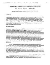
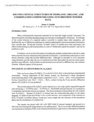
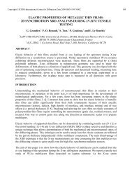
and Γ = 0.52 and yielded 39% peak reflectivity and a <strong>rocking</strong> <strong>curve</strong> width of 76<br />
arcseconds at a Bragg angle of 1.16 degrees. The experimental and modeled reflectivity<br />
<strong>curve</strong>s are shown in Figure 2, and the model parameters are in Table 1. Using these layer<br />
parameters and extrapolating to 100 bilayers, this system should yield 49% reflectivity<br />
with a <strong>rocking</strong> <strong>curve</strong> width of 50 arcseconds. The peak reflectivity eventually saturates at<br />
around 55% with 150 bilayers using the parameters determined for our prototype mirror.<br />
1<br />
Experimental and Modeled Reflectivity<br />
for a 60(Ti/C) Multilayer<br />
Reflectivity<br />
0.1<br />
0.01<br />
0.001<br />
0.0001<br />
Experiment<br />
Model<br />
10 -5<br />
10 -6<br />
0 0.5 1 1.5 2 2.5 3 3.5 4<br />
Grazing Angle (deg)<br />
Figure 2. Experimental and modeled reflectivity for a 60 bilayer Ti/C <strong>multilayer</strong> mirror. The first Bragg<br />
peak at 1.16° has a peak reflectivity of 39% and a FWHM of 76 arcseconds (0.021 degrees).<br />
Layer Thickness (Å) Interface (Å) Density (g/cm 3 )<br />
Ti 20.2 2.4 4.49<br />
C 18.6 4.2 2.27<br />
Glass --- 1.0 2.55<br />
Table 1. Modeled parameters for the prototype 60 bilayer Ti/C <strong>multilayer</strong> mirror.
Copyright(c)JCPDS-International Centre for Diffraction Data 2000,Advances in X-<strong>ray</strong> Analysis,Vol.43 226<br />
1<br />
100x(Ti/C) and 150x(Ti/C)<br />
0.6<br />
0.1<br />
100x(Ti/C)<br />
150x(Ti/C)<br />
0.5<br />
Reflectivity<br />
0.01<br />
0.001<br />
Reflectivity<br />
0.4<br />
0.3<br />
100x(Ti/C)<br />
150x(Ti/C)<br />
0.2<br />
0.0001<br />
0.1<br />
10 -5<br />
0 0.2 0.4 0.6 0.8 1 1.2 1.4 1.6<br />
0<br />
1.1 1.15 1.2 1.25<br />
Grazing Angle (deg)<br />
Figure 3. Extrapolated performance of 100 and 150 bilayer Ti/C <strong>mirrors</strong> based on the model parameters<br />
from the prototype 60 bilayer sample.<br />
Experimental and Modeled Reflectivity<br />
for 20x(Si/Si 3<br />
N 4<br />
) Multilayer<br />
10 0 0 0.5 1 1.5 2 2.5 3<br />
10 -1<br />
10 -2<br />
thick (Å) inter (Å) density<br />
Si 70.6 3.5 2.68<br />
20x(<br />
Si 3<br />
N 4<br />
16.8 1.1 3.13<br />
Si 61.9 1.0 2.66<br />
Flt Gls 1.0 2.52<br />
Reflectivity<br />
10 -3<br />
10 -4<br />
Experiment<br />
Model<br />
10 -5<br />
10 -6<br />
10 -7<br />
Grazing Angle (deg)<br />
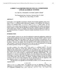
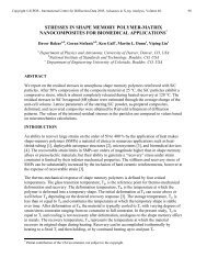
Figure 4. Experimental and modeled reflectivity for a 20 bilayer Si/Si 3 N 4 multiayer mirror. The total<br />
bilayer thickness is 78.7 Å, and Γ = 0.21. Further simulations indicate that Γ = 0.5 yields the highest peak<br />
reflectivity. The first Bragg peak has a reflectivity of 3% and a <strong>rocking</strong> <strong>curve</strong> of 77 arcseconds.
Copyright(c)JCPDS-International Centre for Diffraction Data 2000,Advances in X-<strong>ray</strong> Analysis,Vol.43 227<br />
The next system investigated was a Si/Si 3 N 4 combination, where the resulting mass<br />
density differs by only 0.5 g/cm 3 (modeled ρ Si = 2.66 g/cm 3 and ρ Si3N4 = 3.15 g/cm 3 ). Our<br />
first attempt was a mirror with 20 bilayers which yields 3% reflectivity and a <strong>rocking</strong><br />
<strong>curve</strong> of 77 arcseconds at a Bragg angle of 0.6 degrees. A second mirror with 75 bilayers<br />
yields 12% reflectivity at 0.82 degrees. Again, taking the modeled layer parameters and<br />
extrapolating to 150 bilayers, this bilayer combination should yield 50% reflectivity and a<br />
<strong>rocking</strong> <strong>curve</strong> of 33 arcseconds at a Bragg angle of 1.1 degrees. (The peak reflectivity<br />
begins to saturate at ~60%, but not until >300 bilayers.)<br />
Finally, the most scientifically interesting combination presented here comes when we<br />
utilize the full power of our dual ion beam system and modify the density of component<br />
layers in the bilayer. By appropriate application of the assist beam during deposition, we<br />
can control the density of carbon layers from as low as 2.1 g/cm 3 to as high as 2.86<br />
g/cm 3 . 1 By turning the assist beam on and off during carbon deposition, we have<br />
produced <strong>multilayer</strong> x-<strong>ray</strong> <strong>mirrors</strong> using alternating high and low-density carbon layers<br />
(HDC and LDC respectively). Our first prototype mirror with 24 layer pairs (Figure 5a)<br />
has a peak reflectivity of 1% and a <strong>rocking</strong> <strong>curve</strong> of 72 arcseconds at a Bragg angle of 0.6<br />
degrees. A second mirror with 50 layer pairs (Figure 5b) has a peak reflectivity of 4%<br />
with a <strong>rocking</strong> <strong>curve</strong> of 45 arcseconds also at 0.6 degrees.<br />
a) b)<br />
Experimental and Modeled Reflectivity<br />
of a 24 bilayer HDC/LDC Mirror<br />
Experimental Reflectivity of a 50 bilayer<br />
HDC/LDC Mirror<br />
10 -1<br />
10 -1<br />
Reflectivity<br />
10 -2<br />
10 -3<br />
10 0 0 0.5 1 1.5 2<br />
Experiment<br />
Model<br />
Reflectivity<br />
10 0 0 0.5 1 1.5 2<br />
10 -2<br />
10 -3<br />
10 -4<br />
10 -4<br />
10 -5<br />
10 -5<br />
10 -6<br />
10 -6<br />
Grazing Angle (deg)<br />
Grazing Angle (deg)<br />
Figure 5. a)Experimental and modeled reflectivity of a 24 bilayer HDC/LDC mirror. The total bilayer<br />
thickness is 60.9 Å and Γ = 0.63. b) Experimental reflecitivity of a 50 bilayer HDC/LDC <strong>multilayer</strong>. The<br />
total bilayer thickness in this case is 79.5 Å and Γ = 0.50. With the particular incident beam optics used for<br />
these measurements, the beam is not sufficiently <strong>narrow</strong> in angle to resolve the Kiessig fringes of the 50<br />
bilayer mirror. The oscillations that appear are an aliasing effect between the incident beam and the actual<br />
fringes.<br />
Simulations based on these results indicate that a mirror made with 100 bilayers of high<br />
and low-density carbon will yield a peak reflectivity of 33% and a <strong>rocking</strong> <strong>curve</strong> of 25<br />
arcseconds, while 150 bilayers will yield a peak reflectivity of 50% and a <strong>rocking</strong> <strong>curve</strong><br />
of 19 arcseconds. One important difficulty in this system is that carbon layers tend to be<br />
deposited under extremely high compression, causing either bowing of thin substrates<br />
such as silicon wafers or shattering of the mirror stack after a large number of bilayers are
Copyright(c)JCPDS-International Centre for Diffraction Data 2000,Advances in X-<strong>ray</strong> Analysis,Vol.43 228<br />
deposited. At least one deposition method has been proposed to alleviate this problem, 2<br />
but it has not yet been implemented in our laboratory.<br />
Extrapolated Reflectivity for 100x(HDC/LDC)<br />
Extrapolated Reflectivity for 150x(HDC/LDC)<br />
10 -1<br />
10 -1<br />
10 -2<br />
10 -2<br />
Reflectivity<br />
10 0 0 0.5 1 1.5 2<br />
10 -3<br />
10 -4<br />
Reflectivity<br />
10 0 0 0.5 1 1.5 2<br />
10 -3<br />
10 -4<br />
10 -5<br />
10 -5<br />
10 -6<br />
10 -6<br />
10 -7<br />
10 -7<br />
Grazing Angle (deg)<br />
Grazing Angle (deg)<br />
Figure 6. Extrapolated reflectivity <strong>curve</strong>s for <strong>mirrors</strong> using 100 and 150 bilayers of high-density and lowdensity<br />
carbon. The simulations are based on a bilayer thickness of 80 Å and Γ = 0.5. The peak reflectivity<br />
at the first Bragg peak are 33% and 50% respectively.<br />
Conclusions<br />
The potential for producing <strong>narrow</strong> <strong>rocking</strong> <strong>curve</strong> <strong>multilayer</strong>s has been demonstrated<br />
using a few examples of prototypes from our deposition laboratory. The current lack of x-<br />
<strong>ray</strong> optics that operate in the range between 16 and 100 arcseconds can be addressed with<br />
by the appropriate choice of materials for the mirror system. All three of the material<br />
systems described here should be able to produce <strong>mirrors</strong> with greater than 50%<br />
reflectivity, and <strong>rocking</strong> <strong>curve</strong>s of 50 arcseconds or less.<br />
Such <strong>mirrors</strong> should have useful application in a variety of areas. In wavelength<br />
dispersive x-<strong>ray</strong> fluorescence, <strong>mirrors</strong> with low atomic number layers can scan a wide<br />
range of hard x-<strong>ray</strong> wavelengths without the hindrance of absorption edges. In diffraction<br />
applications, one may be able to choose a mirror with the most appropriate <strong>rocking</strong> <strong>curve</strong>,<br />
while maintaining the highest flux throughput possible. Also as can be seen by comparing<br />
the Pt/C simulation to the other <strong>curve</strong>s presented, the reflectivity away from the Bragg<br />
peaks is much lower in these low contrast systems, significantly reducing the background<br />
even before other measures are incorporated.<br />
1 J. Pedulla, A. Bartos and R. D. Deslattes, “Hard High Density Carbon Thin Films for X-<strong>ray</strong> Multilayers<br />
Optics”, MRS Symp. Proc., 342 (1994).<br />
2 M. Gioti, S. Logothetidis, and C. Charitidis, “Stress relaxation and stability in thick amorphous carbon<br />
films deposited in layer structure”, Appl. Phys. Lett., 73, 184 (1998).