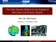
The Finite Element Method for the Analysis of Non-Linear and ...
The Finite Element Method for the Analysis of Non-Linear and ...
The Finite Element Method for the Analysis of Non-Linear and ...

You also want an ePaper? Increase the reach of your titles
YUMPU automatically turns print PDFs into web optimized ePapers that Google loves.
<strong>The</strong> Beam <strong>Element</strong> in Large Displacements<br />
Along <strong>the</strong> lines <strong>of</strong> <strong>the</strong> truss element <strong>for</strong>mulation we need to express <strong>the</strong><br />
coordinates <strong>of</strong> a r<strong>and</strong>om point within <strong>the</strong> beam element. Using (r, s, t) as<br />
<strong>the</strong> Cartesian coordinates at a point within an element with N nodal<br />
points, this is written:<br />
t x i =<br />
N∑<br />
N t k x k i + t 2<br />
k=1<br />
N∑<br />
k=1<br />
a k N k t V k<br />
ti + s 2<br />
N∑<br />
k=1<br />
b k N k t V k<br />
si, i = 1, 2, 3<br />
Vectors V s <strong>and</strong> V t define <strong>the</strong> orientation <strong>of</strong> <strong>the</strong> cross-section <strong>for</strong> <strong>the</strong> beam:<br />
<strong>The</strong>y are normal to <strong>the</strong> axis <strong>of</strong> <strong>the</strong> beam <strong>and</strong> to each o<strong>the</strong>r. <strong>The</strong> values a<br />
<strong>and</strong> b define <strong>the</strong> size <strong>of</strong> <strong>the</strong> cross section <strong>of</strong> <strong>the</strong> beam.<br />
<strong>The</strong> relative displacement components would be:<br />
t u i = t x i − 0 x i<br />
u i = t + ∆ t x i − t x i<br />
are <strong>the</strong> incremental components<br />
Institute <strong>of</strong> Structural Engineering <strong>Method</strong> <strong>of</strong> <strong>Finite</strong> <strong>Element</strong>s II 38