A New Program for the Design of Cable-Stayed Bridges Summary 1 ...
A New Program for the Design of Cable-Stayed Bridges Summary 1 ...
A New Program for the Design of Cable-Stayed Bridges Summary 1 ...

Create successful ePaper yourself
Turn your PDF publications into a flip-book with our unique Google optimized e-Paper software.
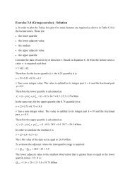
Fig. 4 Step 3. The geometry <strong>of</strong> <strong>the</strong> structure segment cut<br />
out and <strong>the</strong> geometry <strong>of</strong> <strong>the</strong> finite element used to<br />
model it differ by <strong>the</strong> initial displacements a initial<br />
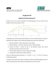
Fig. 5 Step 4. The finite element submitted to <strong>the</strong> initial<br />
self-equilibrating <strong>for</strong>ce f assumes <strong>the</strong> same geometry as<br />
<strong>the</strong> structure segment cut out<br />
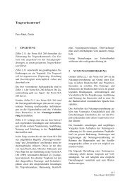
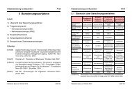
Fig. 6 Section idealization used <strong>for</strong> composite beam<br />
elements<br />
displacements a initial . The <strong>for</strong>ces f are<br />
found by multiplying <strong>the</strong> element local<br />
stiffness matrix k with a initial :<br />
f = k . a initial (2)<br />
The components <strong>of</strong> <strong>the</strong> vector f, like<br />
<strong>for</strong> any kind <strong>of</strong> element load, are to be<br />
assembled in <strong>the</strong> global load vector<br />
every time <strong>the</strong> element is part <strong>of</strong> <strong>the</strong><br />
model, its local stiffness matrix k<br />
being assembled in <strong>the</strong> global stiffness<br />
matrix.<br />
Being initial, i.e. corresponding to a<br />
de<strong>for</strong>med but stress-free state, <strong>the</strong><br />
contribution from f to <strong>the</strong> section<br />
<strong>for</strong>ces has to be ignored during post<br />
processing, i.e. <strong>the</strong> section <strong>for</strong>ces<br />
induced by f in <strong>the</strong> element have to be<br />
subtracted from <strong>the</strong> section <strong>for</strong>ces<br />
found from <strong>the</strong> nodal displacements <strong>of</strong><br />
<strong>the</strong> global solution. This subtraction<br />
does not affect <strong>the</strong> equilibrium in <strong>the</strong><br />
structure because f is self-equilibrating:<br />
this is a property <strong>of</strong> local stiffness<br />
matrices which, being singular, always<br />
deliver self-equilibrating <strong>for</strong>ces group<br />
if multiplied with any nodal<br />
displacement vector.<br />
Initial displacements have to be taken<br />
into account in a slightly different way<br />
<strong>for</strong> <strong>the</strong> composite beam element<br />
specially developed <strong>for</strong> <strong>the</strong> program<br />
BRIDE, which allows to take <strong>the</strong> bond<br />
between concrete and its underlying<br />
steel pr<strong>of</strong>ile into account (see figure 6).<br />
The composite beam element takes<br />
bond into account by merging into a<br />
single combined section <strong>the</strong> section <strong>of</strong><br />
<strong>the</strong> cast concrete and <strong>the</strong> section <strong>of</strong> <strong>the</strong><br />
steel pr<strong>of</strong>ile, which is modelled with a<br />
so-called <strong>for</strong>mwork element. For<br />
composite beam elements f is found as<br />
follows:<br />
f = k co . a co h – q fo co + k ca . (a ca cr + a ca sh ) + k fo . (a fo cr + a fo sh ) (3)<br />
where k co is <strong>the</strong> stiffness matrix computed with <strong>the</strong> combined section, a co h and q fo co are <strong>the</strong><br />
displacements and <strong>the</strong> nodal <strong>for</strong>ces <strong>of</strong> <strong>the</strong> <strong>for</strong>mwork beam during <strong>the</strong> casting stage, k ca and k fo are<br />
<strong>the</strong> stiffness matrices <strong>of</strong> <strong>the</strong> cast concrete part and <strong>of</strong> <strong>the</strong> <strong>for</strong>mwork beam, respectively, with no<br />
bond between <strong>the</strong>m. a ca cr , a ca sh , a fo cr and a fo sh are <strong>the</strong> initial displacements <strong>for</strong> <strong>the</strong> <strong>for</strong>mwork beam<br />
and <strong>for</strong> <strong>the</strong> cast concrete beam (it is justified to have also initial displacements due to creep and<br />
shrinkage <strong>for</strong> <strong>the</strong> <strong>for</strong>mwork since this might be in pre-cast concrete). All this <strong>for</strong>ces, stiffness<br />
matrices and displacements are expressed relatively to <strong>the</strong> centroid <strong>of</strong> <strong>the</strong> combined section. The<br />
element is <strong>the</strong>n excentrically connected to its nodes.<br />
The fact <strong>of</strong> not taking bond into account <strong>for</strong> k ca and k fo is a conspicuous simplification which is<br />
acceptable because <strong>the</strong> self-equilibrating load f is applied on <strong>the</strong> un-displaced composite element<br />
(whose stiffness takes bond into account) hence differences between <strong>the</strong> initial displacements <strong>of</strong> <strong>the</strong><br />
cast concrete a cr ca + a sh ca and those <strong>of</strong> <strong>the</strong> <strong>for</strong>mwork a cr fo + a sh fo lead just to differences in <strong>the</strong> section