Assignment #3 Method of Finite Elements II
Assignment #3 Method of Finite Elements II
Assignment #3 Method of Finite Elements II

You also want an ePaper? Increase the reach of your titles
YUMPU automatically turns print PDFs into web optimized ePapers that Google loves.
ethod <strong>of</strong> <strong>Finite</strong> <strong>Elements</strong> <strong>II</strong><br />
<strong>Assignment</strong> <strong>#3</strong><br />
<strong>Method</strong> <strong>of</strong> <strong>Finite</strong> <strong>Elements</strong> <strong>II</strong><br />
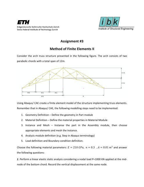
Consider the arch truss structure presented in the following figure. The arch consists <strong>of</strong> two<br />
parabolic chords with a total span <strong>of</strong> 12m.<br />
Using Abaqus/ CAE create a finite element model <strong>of</strong> the structure implementing truss elements.<br />
Remember that in Abaqus/ CAE, the following modelling steps need to be implemented:<br />
1. Geometry Definition – Define the geometry in Part module<br />
2. Material Definition – Define the material properties in Material Module<br />
3. Instance and Mesh – Instanse the part in the Assembly module, then choose<br />
appropriate elements and mesh the instance.<br />
4. Analysis module definition (e.g. Step in Abaqus terminology)<br />
5. Load definition and Boundary condition definition.<br />
Choose the following material parameters: E = 210 GPa, n = 0.3<br />
the following questions:<br />
, A = 0.01 m 2 and answer<br />
1. Perform a linear elastic static analysis considering a nodal load P=1000 KN applied at the midnode<br />
<strong>of</strong> the bottom chord. Record the vertical displacement at the same node.
2. Taking into account geometrical nonlinearities (Remember to check the Nlgeom checkbox in<br />
step definition), and choosing an incremental-iterative procedure (i.e. Static Riks <strong>Method</strong>)<br />
record the load path <strong>of</strong> the structure. Appropriate values for fields such as number <strong>of</strong><br />
increments, error tolerances and stopping criteria should be chosen and justified accordingly.<br />
3. Considering a von-Mises type material with an initial yield stress <strong>of</strong> 235 MPa and an ultimate<br />
strength <strong>of</strong> 360 MPa (achieved at a plastic strain ε p,u =6%), define an elasto-plastic material in<br />
the material definition and perform a nonlinear inelastic analysis, neglecting geometrical<br />
nonlinearities. Record the derived load path (uncheck the Nlgeom checkbox in step definiotion).<br />
4. Finally, perform an incremental analysis where both material and geometrical nonlinearities<br />
are considered. Present a graph where all four derived solutions are plotted.<br />
4i. Try to explain the differences, if any, between the derived load-paths.<br />
4ii. Which load-path should be appropriate for design purposes and why.<br />
5. Without performing any computation at all, would the solution <strong>of</strong> the problem be any<br />
different if beam elements with end releases have been used instead <strong>of</strong> truss elements?