

3A2993B, GLC2200 Wiring Harness Kit, Instructions ... - Graco Inc.
3A2993B, GLC2200 Wiring Harness Kit, Instructions ... - Graco Inc.
3A2993B, GLC2200 Wiring Harness Kit, Instructions ... - Graco Inc.

You also want an ePaper? Increase the reach of your titles
YUMPU automatically turns print PDFs into web optimized ePapers that Google loves.
<strong>Instructions</strong><br />
GLC 2200 <strong>Wiring</strong><br />
<strong>Harness</strong> <strong>Kit</strong><br />
<strong>3A2993B</strong><br />
EN<br />
Used to interface the GLC 2200 Lubrication Controller to pump and pump accessories. For<br />
professional use only.<br />
Not approved for use in European explosive atmosphere locations.<br />
<strong>Kit</strong> Nos.: 24P314<br />
<strong>Kit</strong> is rated IP65.<br />
Important Safety <strong>Instructions</strong><br />
Read all warnings and instructions in this<br />
manual and the <strong>GLC2200</strong> Lubrication Controller<br />
instruction manual included with your unit. Save<br />
these instructions.<br />
<strong>Instructions</strong><br />
1. Verify the Connector end of the cable is NOT<br />
plugged in to the <strong>GLC2200</strong> controller.<br />
2. Remove 2 to 3 inches of the outer insulation (a) from<br />
bare end of the cable as shown FIG. 1.<br />
4. Using the <strong>Wiring</strong> Key Table provided on the reverse<br />
side of these instructions, connect components to<br />
cable wires matching each wire color shown on the<br />
Table to the related component.<br />
Verify all negative and positive wire colors are correctly<br />
assigned.<br />
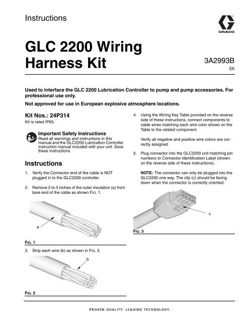
5. Plug connector into the <strong>GLC2200</strong> unit matching pin<br />
numbers to Connector Identification Label (shown<br />
on the reverse side of these instructions).<br />
NOTE: The connector can only be plugged into the<br />
<strong>GLC2200</strong> one way. The clip (c) should be facing<br />
down when the connector is correctly oriented.<br />
.<br />
c<br />
a<br />
FIG. 3<br />
FIG. 1<br />
3. Strip each wire (b) as shown in FIG. 2.<br />
b<br />
FIG. 2
<strong>Wiring</strong> Diagram<br />
V<br />
M<br />
1 2 3 4 5<br />
6 7 8 9 10<br />
-<br />
+<br />
9A Fuse<br />
M = Motor, pump power or solenoid<br />
V = Electric vent valve for injector-based systems<br />
<strong>Wiring</strong> Key<br />
Pin Color Description +/-<br />
1 Blue Pump -<br />
2 Purple Alarm -<br />
3 Brown Low Level -<br />
4 White Pressure Cycle Switch -<br />
5 Black Voltage Input -<br />
6 Orange Pump +<br />
7 Green Alarm +<br />
8 Yellow Low Level +<br />
9 Gray Pressure Cycle Switch +<br />
10 Red Voltage Input +<br />
Connector Identification Label<br />
PIN 1 2 3 4 5<br />
9A<br />
2A<br />
P/C +9V<br />
+30V<br />
PIN 6 7 8 9 10<br />
All written and visual data contained in this document reflects the latest product information available at the time of publication.<br />
<strong>Graco</strong> reserves the right to make changes at any time without notice.<br />
For patent information, see www.graco.com/patents.<br />
Original instructions. This manual contains English. MM 3A2993<br />
<strong>Graco</strong> Headquarters: Minneapolis<br />
International Offices: Belgium, China, Japan, Korea<br />
GRACO INC. AND SUBSIDIARIES • P.O. BOX 1441 • MINNEAPOLIS MN 55440-1441 • USA<br />
Copyright 2012, <strong>Graco</strong> <strong>Inc</strong>. All <strong>Graco</strong> manufacturing locations are registered to ISO 9001.<br />
www.graco.com<br />
December 2013


