Grundlagen FlexRay - Institut für Automatisierungs- und ...
Grundlagen FlexRay - Institut für Automatisierungs- und ...
Grundlagen FlexRay - Institut für Automatisierungs- und ...

Create successful ePaper yourself
Turn your PDF publications into a flip-book with our unique Google optimized e-Paper software.
<strong>Gr<strong>und</strong>lagen</strong> <strong>FlexRay</strong> BasicsV 1.1 17<br />
Unterminiertes Kabelende<br />
Figure 2.8 Open termination [FREPLS06]<br />
All terminating resistors in a branch are parallel. The resulting resistance R DCLoad has to be<br />
between 40 and 55Ω. The usage of a choke is allowed, too. Depending on the topology, there<br />
are different setups for bus termination and the placement of the resistors. The resulting<br />
resistance has to be in the defined range for R DCLoad .<br />
2.4 Physical topology<br />
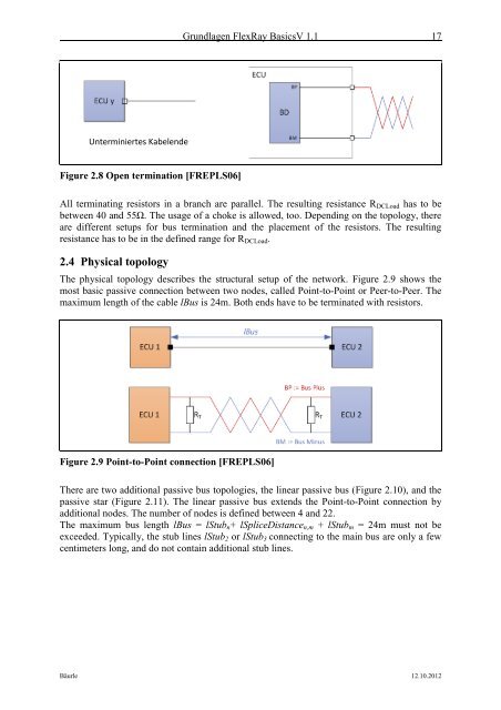
The physical topology describes the structural setup of the network. Figure 2.9 shows the<br />
most basic passive connection between two nodes, called Point-to-Point or Peer-to-Peer. The<br />
maximum length of the cable lBus is 24m. Both ends have to be terminated with resistors.<br />
Figure 2.9 Point-to-Point connection [FREPLS06]<br />
There are two additional passive bus topologies, the linear passive bus (Figure 2.10), and the<br />
passive star (Figure 2.11). The linear passive bus extends the Point-to-Point connection by<br />
additional nodes. The number of nodes is defined between 4 and 22.<br />
The maximum bus length lBus = lStub n + lSpliceDistance n,m + lStub m = 24m must not be<br />
exceeded. Typically, the stub lines lStub 2 or lStub 3 connecting to the main bus are only a few<br />
centimeters long, and do not contain additional stub lines.<br />
Bäurle 12.10.2012