Laser processing of materials - Indian Academy of Sciences
Laser processing of materials - Indian Academy of Sciences
Laser processing of materials - Indian Academy of Sciences

Create successful ePaper yourself
Turn your PDF publications into a flip-book with our unique Google optimized e-Paper software.
Sādhanā Vol.28,Parts3&4, June/August 2003, pp. 495–562. © Printed in India<br />
<strong>Laser</strong> <strong>processing</strong> <strong>of</strong> <strong>materials</strong><br />
J DUTTA MAJUMDAR and I MANNA ∗<br />
Metallurgical and Materials Engineering Department, <strong>Indian</strong> Institute <strong>of</strong><br />
Technology, Kharagpur 721 302, India<br />
e-mail: imanna@metal.iitkgp.ernet.in<br />
Abstract. Light amplification by stimulated emission <strong>of</strong> radiation (laser) is a<br />
coherent and monochromatic beam <strong>of</strong> electromagnetic radiation that can propagate<br />
in a straight line with negligible divergence and occur in a wide range <strong>of</strong> wavelength,<br />
energy/power and beam-modes/configurations. As a result, lasers find wide<br />
applications in the mundane to the most sophisticated devices, in commercial to<br />
purely scientific purposes, and in life-saving as well as life-threatening causes. In<br />
the present contribution, we provide an overview <strong>of</strong> the application <strong>of</strong> lasers for<br />
material <strong>processing</strong>. The processes covered are broadly divided into four major<br />
categories; namely, laser-assisted forming, joining, machining and surface engineering.<br />
Apart from briefly introducing the fundamentals <strong>of</strong> these operations, we<br />
present an updated review <strong>of</strong> the relevant literature to highlight the recent advances<br />
and open questions. We begin our discussion with the general applications <strong>of</strong> lasers,<br />
fundamentals <strong>of</strong> laser–matter interaction and classification <strong>of</strong> laser material <strong>processing</strong>.<br />
A major part <strong>of</strong> the discussion focuses on laser surface engineering that has<br />
attracted a good deal <strong>of</strong> attention from the scientific community for its technological<br />
significance and scientific challenges. In this regard, a special mention is made<br />
about laser surface vitrification or amorphization that remains a very attractive but<br />
unaccomplished proposition.<br />
Keywords.<br />
<strong>Laser</strong> <strong>processing</strong>; laser–matter interaction; laser surface vitrification.<br />
1. Introduction<br />
<strong>Laser</strong>, an acronym for light amplification by stimulated emission <strong>of</strong> radiation, is essentially a<br />
coherent, convergent and monochromatic beam <strong>of</strong> electromagnetic radiation with wavelength<br />
ranging from ultra-violet to infrared [1]. <strong>Laser</strong> can deliver very low (∼mW) to extremely high<br />
(1–100 kW) focused power with a precise spot size/dimension and interaction/pulse time<br />
(10 −3 to 10 −15 s) on to any kind <strong>of</strong> substrate through any medium [1–4]. <strong>Laser</strong> is distinguished<br />
from other electromagnetic radiation mainly in terms <strong>of</strong> its coherence, spectral purity and<br />
ability to propagate in a straight line. As a result, laser has wide applications from very mundane<br />
(bar code scanner) to most sophisticated (3-dimensional holography), mere commercial<br />
(audio recording) to purely scientific (spectroscopy), routine (printer) to futuristic (optical<br />
∗ References in this paper have not been cited or prepared in journal format<br />
495
496 J Dutta Majumdar and I Manna<br />
computer), and life saving (surgery) to life threatening (weapons/guide). <strong>Laser</strong> is useful in<br />
metrology (length/velocity/ roughness measurement), entertainment (laser light show), medical<br />
diagnostics and surgery/therapy and optical communication/computation. From printer<br />
to pointer, surgery to spectroscopy, isotope separation to invisible surveillance and medical<br />
to material treatment, laser finds a ubiquitous presence mainly for some unique combination<br />
<strong>of</strong> properties. These important properties that justify the use <strong>of</strong> laser in such a wide spectrum<br />
<strong>of</strong> applications are (a) spatial and temporal coherence (i.e., phase and amplitude are unique),<br />
(b) low divergence (parallel to the optical axis), (c) high continuous or pulsed power density,<br />
and (d) monochromaticity [1–10].<br />
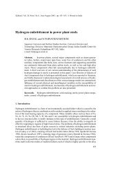
Figure 1 presents a brief overview <strong>of</strong> the application <strong>of</strong> laser in different fields with diverse<br />
objective [1]. Though the list is not exhaustive, it serves to show the diversity <strong>of</strong> application<br />
<strong>of</strong> laser. In some applications, the power output is <strong>of</strong> main concern, e.g. atomic fusion<br />
and isotope separation. Sometimes, the main reason for using laser lies in its spectral purity<br />
and coherence (pollution detection, length/velocity measurement, interferometry, etc.), low<br />
divergence (laser show, pointer/guide, audio-player), or a combination <strong>of</strong> all <strong>of</strong> them (communication,<br />
holography, metrology). Accordingly, a host <strong>of</strong> lasers capable <strong>of</strong> delivering a<br />
wide variety <strong>of</strong> wavelength, energy, temporal/spectral distribution and efficiency have been<br />
developed over the last several decades [1].<br />
In the present contribution, we would confine ourselves to only laser material <strong>processing</strong>.<br />
The intense heat that laser may produce on solid matter enables several types <strong>of</strong> ultrafast,<br />
novel and economical <strong>processing</strong> <strong>of</strong> material that are distinctly advantageous from the<br />
quality, productivity and efficiency point <strong>of</strong> view than that possible with their conventional<br />
counterparts. We will, at first, review the history <strong>of</strong> laser and enlist the main types <strong>of</strong> commercial<br />
laser used in material <strong>processing</strong> before introducing the working principle <strong>of</strong> the most<br />
Applications <strong>of</strong> lasers<br />
Low power applications<br />
High power applications<br />
Communication<br />
Metrology Reprography<br />
Entertainment<br />
Military Chemical<br />
Medical<br />
Heat<br />
source<br />
(LMP)<br />
Optical<br />
fibre<br />
communication,<br />
telecommunication,<br />
optical<br />
data storage<br />
and computation<br />
Holography,<br />
length/velocity<br />
measurement,<br />
inspection,<br />
interferometry,<br />
alignment<br />
Printing<br />
<strong>of</strong> various<br />
kinds,<br />
scanning,<br />
data<br />
storage<br />
<strong>Laser</strong><br />
light<br />
beam<br />
show,<br />
pointers,<br />
audioacoustic<br />
recording<br />
Weapon<br />
guide,<br />
atomic<br />
fusion,<br />
surveillance<br />
Spectroscopy,<br />
isotropeseparation,<br />
photochemical<br />
deposition,<br />
pollution<br />
control<br />
Angioplasty,<br />
tumour<br />
therapy,<br />
skin/dental/<br />
eye surgery,<br />
dermatology<br />
Forming,<br />
joining<br />
machining,<br />
rapid<br />
prototyping,<br />
manufacturing,<br />
coating/<br />
deposition,<br />
surface<br />
engineering<br />
Figure 1.<br />
Application spectrum <strong>of</strong> lasers.
<strong>Laser</strong> <strong>processing</strong> <strong>of</strong> <strong>materials</strong> 497<br />
commonly used ones. Before embarking upon reviewing the current status <strong>of</strong> laser material<br />
<strong>processing</strong>, we will discuss the physics <strong>of</strong> laser–matter interaction and classify the different<br />
types <strong>of</strong> laser <strong>processing</strong> <strong>of</strong> <strong>materials</strong>. Finally, we will present a comprehensive update<br />
<strong>of</strong> the studies on different types <strong>of</strong> laser material <strong>processing</strong> and highlight the scientific and<br />
technological aspects <strong>of</strong> importance. In order to confine ourselves to the prescribed limit, we<br />
have deliberately reviewed the literature published from 1995 onwards. This cut-<strong>of</strong>f, even<br />
though arbitrary, was unavoidable due to restriction on the length <strong>of</strong> the paper. However, this<br />
restriction applies only to the cited literatures but not to discussing the fundamentals <strong>of</strong> the<br />
subject. For further details on laser material <strong>processing</strong>, the textbook by Steen [1] is the most<br />
comprehensive source <strong>of</strong> information.<br />
2. History <strong>of</strong> laser and its application<br />
<strong>Laser</strong> is surely one <strong>of</strong> the greatest innovations <strong>of</strong> 20th century. Its continued development has<br />
been an exciting chapter in the history <strong>of</strong> science, engineering and technology. As a versatile<br />
source <strong>of</strong> pure energy in a highly concentrated form, laser has emerged as an attractive<br />
tool and research instrument with potential for applications in an extraordinary variety <strong>of</strong><br />
fields.<br />
The initial foundation <strong>of</strong> laser theory was laid by Einstein [11]. Subsequently, Kopfermann<br />
& Ladenburg [12] presented the first experimental confirmation <strong>of</strong> Einstein’s prediction.<br />
In 1960, Maiman [13] developed a ruby laser for the first time. This was followed by<br />
much basic development <strong>of</strong> lasers from 1962 to 1968. Almost all important types <strong>of</strong> lasers<br />
including semiconductor lasers, Nd:YAG lasers, CO 2 gas lasers, dye lasers and other gas<br />
lasers were invented in this era. After 1968, the existing lasers were designed and fabricated<br />
with better reliability and durability. By mid 1970s more reliable lasers were made available<br />
for truly practical applications in the industrial applications such as cutting, welding,<br />
drilling and marking. During the 1980s and early 1990s the lasers were explored for surface<br />
related applications such as heat treatment, cladding, alloying, glazing and thin film<br />
deposition.<br />
Table 1 summarises commercially available lasers and their main areas <strong>of</strong> application.<br />
Depending on the type <strong>of</strong> laser and wavelength desired, the laser medium is solid, liquid or<br />
gaseous. Different laser types are commonly named according to the state or the physical<br />
properties <strong>of</strong> the active medium. Consequently, we have crystal, glass or semiconductor, solid<br />
state lasers, liquid lasers, and gas lasers. The latter (gas lasers) can be further subdivided into<br />
neutral atom lasers, ion lasers, molecular lasers and excimer lasers. The typical commercially<br />
available lasers for material <strong>processing</strong> are (a) solid state crystal or glass laser – Nd:YAG,<br />
Ruby, (b) semiconductor laser – AlGaAs, GaAsSb and GaAlSb lasers, (c) dye or liquid laserssolutions<br />
<strong>of</strong> dyes in water/alcohol and other solvents, (d) neutral or atomic gas lasers – He–Ne<br />
laser, Cu or Au vapour laser, (e) ionized gas lasers or ion lasers – argon (Ar + ) and krypton<br />
(Kr + ) ion lasers, (f) molecular gas lasers – CO 2 or CO laser, and (g) excimer laser – XeCl,<br />
KrF, etc. Wavelengths <strong>of</strong> presently available lasers cover the entire spectral range from the<br />
far-infrared to the s<strong>of</strong>t X-ray.<br />
3. Generation <strong>of</strong> laser<br />
<strong>Laser</strong> is a coherent and amplified beam <strong>of</strong> electromagnetic radiation or light. The key element<br />
in making a practical laser is the light amplification achieved by stimulated emission due to the
498 J Dutta Majumdar and I Manna<br />
Table 1. Commercially available lasers and their industrial applications.<br />
Year <strong>of</strong> Commercialised<br />
<strong>Laser</strong> discovery since Application<br />
Ruby 1960 1963 Metrology, medical applications, inorganic<br />
material <strong>processing</strong><br />
Nd-Glass 1961 1968 Length and velocity measurement<br />
Diode 1962 1965 Semiconductor <strong>processing</strong>, biomedical<br />
applications, welding<br />
He–Ne 1962 Light-pointers, length/velocity measurement,<br />
alignment devices<br />
Carbon dioxide 1964 1966 Material <strong>processing</strong>-cutting/joining,<br />
atomic fusion<br />
Nd-YAG 1964 1966 Material <strong>processing</strong>, joining, analytical<br />
technique<br />
Argon ion 1964 1966 Powerful light, medical applications<br />
Dye 1966 1969 Pollution detection, isotope separation<br />
Copper 1966 1989 Isotope separation<br />
Excimer 1975 1976 Medical application, material <strong>processing</strong>,<br />
colouring<br />
incident photons <strong>of</strong> high energy. A laser comprises three principal components, namely, the<br />
gain medium (or resonator), means <strong>of</strong> exciting the gain medium into its amplifying state and<br />
optical delivery/feed back system. Additional provisions <strong>of</strong> cooling the mirrors, guiding the<br />
beam and manipulating the target are also important. The laser medium may be a solid (e.g.<br />
Nd:YAG or neodymium doped yttrium–aluminum–garnet), liquid (dye) or gas (e.g. CO 2 , He,<br />
Ne, etc.). For gas and diode lasers, the energy is usually introduced directly by electric-current<br />
flow, whereas, an intense flash <strong>of</strong> white light produced by incandescent lamps introduces the<br />
excitation energy in solid state crystal lasers. The sudden pumping <strong>of</strong> energy causes the laser<br />
medium to fluoresce and produce intense monochromatic, unidirectional (parallel/convergent)<br />
and coherent rays [1,2].Among the commercially available lasers, CO 2 -laser seems one <strong>of</strong> the<br />
earliest developed and most popular lasers for material <strong>processing</strong> because they are electrically<br />
more efficient (15–20%) and produce higher powers (0·1–50 kW) than other lasers in the<br />
continuous mode. Despite being less efficient in energy coupling with metals due to longer<br />
wavelength (10·6 µm), the higher wall plug (∼ 12%) and quantum (∼ 45%) efficiency and<br />
output power level <strong>of</strong> CO 2 lasers more than compensate for the poor laser–matter energy<br />
coupling capability. On the other hand, Nd:YAG and Ruby lasers possess shorter wavelength<br />
and are more suited to pulsed mode <strong>of</strong> applications requiring deeper penetration, smaller area<br />
coverage and precision treatment <strong>of</strong> <strong>materials</strong> for specific purposes.<br />
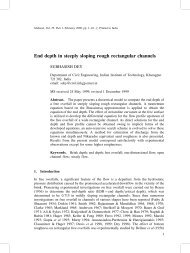
As illustrated in figure 2a, the CO 2 -laser device consists <strong>of</strong> three main parts –againor<br />
laser medium, an optical resonator or cavity with two mirrors, and an energizing or pumping<br />
source that supplies energy to the gain medium. The chemical species in the gain medium<br />
determines the wavelength <strong>of</strong> the optical output. Between the two mirrors, one is a fully<br />
reflecting and the other a partially reflecting one. From the quantum mechanical principle,<br />
when an external energy is supplied to an atom, the irradiated atom attains an excited state
<strong>Laser</strong> <strong>processing</strong> <strong>of</strong> <strong>materials</strong> 499<br />
Figure 2. Schematic set-up <strong>of</strong> continuous wave CO 2 laser. (a) The major constituents <strong>of</strong> the machine,<br />
(b) initial stage <strong>of</strong> energy pumping, (c) excitation and de-excitation <strong>of</strong> the atoms in the medium leading<br />
to emission <strong>of</strong> laser and (d) stimulated emission and formation <strong>of</strong> laser beam.<br />
(figure 2b). The excited atom spontaneously returns to the ground state (E 1 ) from the higher<br />
energy state (E 2 ) by emitting the energy difference as a photon <strong>of</strong> frequency (ν):<br />
ν = (E 2 − E 1 )/h, (1)<br />
where, h is the Planck’s constant. This phenomenon is known as spontaneous emission (figure<br />
2c). A spontaneously emitted photon may in turn excite another atom and stimulate it to<br />
emit a photon by de-exciting it to a lower energy level. This process is called stimulated emission<br />
<strong>of</strong> radiation (figure 2c). The latter is coherent with the stimulating radiation so that the<br />
wavelength, phase and polarization between the two are identical. A photon interacting with<br />
an unexcited atom may get absorbed by it and excite it to higher energy state. This situation,<br />
called ‘population inversion’is created by the pumping source. The photons moving along the<br />
optic axis interact with a large number <strong>of</strong> excited atoms, stimulate them and by this process<br />
get amplified. They are reflected back and forth by the resonator mirrors and pass through<br />
the excited medium creating more photons. In each round trip, a percentage <strong>of</strong> these photons<br />
exit through the partially transmitting mirror as intense laser beam (figure 2d). Finally, the
500 J Dutta Majumdar and I Manna<br />
laser beam is either guided on to the work-piece by using reflecting mirrors or delivered at<br />
the desired site through optical fibres.<br />
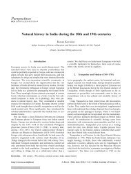
Figure 3 shows a schematic outline <strong>of</strong> a solid state neodymium doped yttrium aluminum<br />
garnet (Nd:YAG). The generation <strong>of</strong> high average power in Nd–YAG laser systems is accomplished<br />
by combining several individually pumped laser rods in a single resonator. Pumping<br />
is performed with arc lamps mounted in a close coupling optical geometry that ensures the<br />
maximum possible absorption <strong>of</strong> visible pump radiation by the laser rod. This optimizes both<br />
pumping efficiency and energy extraction efficiency. Energy pumping selectively energizes<br />
the Nd ions that subsequently lead to a cascading effect and stimulated emission <strong>of</strong> light.<br />
These days, energy pumping is also done with diode lasers <strong>of</strong> appropriate frequency. Nd:YAG<br />
laser has 40% quantum efficiency. However, the overall electrical efficiency <strong>of</strong> YAG lasers is<br />
low. The ratio <strong>of</strong> laser output power to electrical input power lies in the range 0·5–3%. The<br />
major advantages <strong>of</strong> Nd–YAG laser over CO 2 laser lie in its smaller wavelength (1·06 µm)<br />
and ability to deliver laser radiation through optical fibers.<br />
4. <strong>Laser</strong>–matter interaction in material <strong>processing</strong><br />
The input <strong>of</strong> energy or energy deposition process from a pulsed/continuous wave laser beam<br />
into the near-surface regions <strong>of</strong> a solid involves electronic excitation and de-excitation within<br />
an extremely short period <strong>of</strong> time [8–10]. In other words, the laser–matter interaction within<br />
the near-surface region achieves extreme heating and cooling rates (10 3 –10 10 K/s), while the<br />
total deposited energy (typically, 0·1–10 J/cm 2 ) is insufficient to affect, in a significant way,<br />
the temperature <strong>of</strong> the bulk material. This allows the near-surface region to be processed under<br />
extreme conditions with little effect on the bulk properties.<br />
4.1 Lattice heating<br />
The initial stage in all laser-metal <strong>processing</strong> applications involves the coupling <strong>of</strong> laser<br />
radiation to electrons within the metal. This first occurs by the absorption <strong>of</strong> photons from the<br />
Figure 3. Schematic set-up <strong>of</strong> pulsed solid state neodymium–doped yttrium–aluminum–garnet<br />
(Nd:YAG) laser.
<strong>Laser</strong> <strong>processing</strong> <strong>of</strong> <strong>materials</strong> 501<br />
incident laser beam promoting electrons within the metal to states <strong>of</strong> higher energy. Electrons<br />
that have been excited in this manner can divest themselves <strong>of</strong> their excess energy in a variety <strong>of</strong><br />
ways. For example, if the photon energy is large enough, the excited electrons can be removed<br />
entirely from the metal. This is the photoelectric effect and usually requires photon energies<br />
greater than several electron volts. Most laser <strong>processing</strong> applications, however, utilize lasers<br />
emitting photons with relatively low energy. The energy <strong>of</strong> CO 2 laser photons is only 0·12 eV<br />
while the photons obtained from the Nd:YAG laser have about 1·2 eV <strong>of</strong> energy. Electrons<br />
excited by absorption <strong>of</strong> CO 2 or Nd:YAG laser radiation do not therefore have enough energy<br />
to be ejected from the metal surface. Such electrons must, nevertheless, lose energy to return to<br />
an equilibrium state after photon excitation. This occurs when excited electrons are scattered<br />
by lattice defects like usual non-crystalline regions in a crystal such as dislocations and grain<br />
boundaries such as the lattice deformation produced by photons. In either case, the overall<br />
effect is to convert electronic energy derived from the beam <strong>of</strong> incident photons into heat. It<br />
is this heat that is useful (indeed necessary) in all surface treatment applications.<br />
4.2 Energy absorption<br />
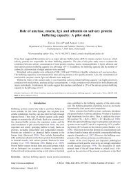
Figure 4 describes the process that is important in electron excitation and excited carrier<br />
relaxation process involved during laser–matter interaction [8]. Photon interaction with matter<br />
occurs usually through the excitation <strong>of</strong> valence and conduction band electrons throughout<br />
the wavelength band from infrared (10 µm) to ultraviolet (0·2 µm) region. Absorption <strong>of</strong><br />
wavelength between 0·2–10 µm leads to intra-band transition (free electrons only) in metals<br />
and inter-band transition (valence to conduction) in semiconductors. Conversion <strong>of</strong> the<br />
absorbed energy to heat involves (a) excitation <strong>of</strong> valence and/or conduction band electrons,<br />
(b) excited electron-phonon interaction within a span <strong>of</strong> 10 −11 –10 −12 s, (c) electron-electron or<br />
electron-plasma interaction, and (d) electron-hole recombination within 10 −9 –10 −10 s (Auger<br />
process). Since free carrier absorption (by conduction band electrons) is the primary route <strong>of</strong><br />
energy absorption in metals, beam energy is almost instantaneously transferred to the lattice<br />
by electron-phonon interaction.<br />
Figure 4. Schematic diagram depicting electron excitation and carrier relaxation process in <strong>materials</strong><br />
subjected to intense laser irradiation.
502 J Dutta Majumdar and I Manna<br />
Figure 5. Spatial pr<strong>of</strong>ile <strong>of</strong> deposited energy following<br />
irradiation <strong>of</strong> solid matter by (a) laser beam<br />
I(z,t) = I o (t)(1 − R) exp(−xz), (b) electron beam –<br />
I(z,t) = I o (t)(1 − R E )f E (X/X p ), and (c) ion beam –<br />
C(z)(Q T / √ [<br />
2πR P )exp −((z − R P )/ √ √ ]<br />
2RP ) .<br />
4.3 Spatial distribution <strong>of</strong> deposited energy<br />
The spatial pr<strong>of</strong>ile <strong>of</strong> deposited energy from laser beam is illustrated in figure 5a. For laser<br />
irradiation, the beam intensity I at a depth z for the normally incident beam <strong>of</strong> initial intensity<br />
I o (in W/m 2 ) is given by [8]<br />
I(z,t) = I o (t)(1 − R) exp(−αz), (2)<br />
where, I o is the incident intensity, t is time, R and α are the reflectivity and absorption coefficients,<br />
respectively. Since α is very high (∼ 10 6 cm −1 ) for metals, light is totally absorbed<br />
within a depth <strong>of</strong> 100–200 Å. The efficiency <strong>of</strong> optical coupling is determined by the reflectivity<br />
(R). R for metals is relatively low at short wavelengths, rises abruptly at a critical<br />
wavelength (related to the plasma frequency <strong>of</strong> the free electron plasma), and then remains<br />
very high at long wavelength [8].<br />
For comparison, the deposited energy pr<strong>of</strong>ile from the other two important directed-energysources,<br />
namely electron and ion beams, are also shown in figure 5b and figure 5c, respectively.<br />
The energy deposition pr<strong>of</strong>ile for electron beam irradiation <strong>of</strong> matter is given by a gaussian<br />
function,<br />
I(z,t) = I o (t)(1 − R E )f E (x/x P ), (3)<br />
where, R E is the reflectivity for e-beam, x P is the distance (x) that coincides with the peak<br />
intensity and f E (x/x P ) is the spatial energy deposition pr<strong>of</strong>ile. The deposition pr<strong>of</strong>ile depends<br />
on the energy loss hence on incident energy and atomic number. Thus, electron beam is<br />
more suited to deep penetration welding than surface engineering applications. Similarly, the<br />
concentration <strong>of</strong> the implanted species in ion beam irradiation does not coincide with the top<br />
surface but lies underneath the surface (4):
<strong>Laser</strong> <strong>processing</strong> <strong>of</strong> <strong>materials</strong> 503<br />
C(z) = [ Q T /(2π) 1/2 ] { [ ( ) ]}<br />
z −<br />
2<br />
RP<br />
R P exp − √ , (4)<br />
2RP<br />
Here, C(z) is the concentration <strong>of</strong> a given species at a vertical distance z, R p is the projected<br />
range/distance and Q T is the dose.<br />
4.4 Heating due to laser irradiation<br />
Usually, the deposited energy <strong>of</strong> laser irradiation is converted into heat on a time scale shorter<br />
than the pulse duration or laser interaction time [8]. The resulting temperature pr<strong>of</strong>ile depends<br />
on the deposited energy pr<strong>of</strong>ile and thermal diffusion rate during laser irradiation. Thermal<br />
diffusivity (D) is related to thermal conductivity (k) and specific heat (C P ) as follows:<br />
D = k/(ρC P ), (5)<br />
where, ρ is the density. The vertical distance (z) over which heat diffuses during the pulse<br />
duration (t p ) is given by, z = (2Dt p ) 1/2 . Here, z in comparison to α −1 determines the<br />
temperature pr<strong>of</strong>ile. The condition <strong>of</strong> α −1 ≪ z is applicable typically for laser irradiation <strong>of</strong><br />
metals.<br />
Under the one dimensional heat flow condition, the heat balance equation may be expressed<br />
as [5]:<br />
ρc p<br />
∂T (z, t)<br />
∂T<br />
= Q(z, t) + ∂ (z, t)<br />
k∂T<br />
∂z ∂z<br />
where, T and Q are the temperature and power density at a given vertical distance <strong>of</strong> depth<br />
(z) and time (t), respectively. Q follows a functional relation with z same as (2). The heat<br />
balance equation (6) may be solved analytically if the coupling parameters (α and R) and<br />
<strong>materials</strong> parameters (ρ,k and c P ) are not temperature and phase dependent. However, phase<br />
changes are unavoidable except in solid state <strong>processing</strong>. Thus, the heat balance equation is<br />
solved by numerical techniques like finite difference/element methods.<br />
Depending on the temperature pr<strong>of</strong>ile, the irradiated material may undergo only heating,<br />
melting or vapourization. For surface melting and subsequent re-solidification, the solid-liquid<br />
interface initially moves away from and then travels back to the surface with the velocity<br />
as high as 1–30 m/s. The interface velocity is given by v ∝ (T m − T i ), where T m and T i<br />
are the melting and interface temperatures, respectively [8]. Further details on mathematical<br />
modelling <strong>of</strong> heat transfer in laser material <strong>processing</strong> may be obtained in several textbooks<br />
[5,6].<br />
(6)<br />
5. <strong>Laser</strong> material <strong>processing</strong><br />
The increasing demand <strong>of</strong> laser in material <strong>processing</strong> can be attributed to several unique<br />
advantages <strong>of</strong> laser namely, high productivity, automation worthiness, non-contact <strong>processing</strong>,<br />
elimination <strong>of</strong> finishing operation, reduced <strong>processing</strong> cost, improved product quality,<br />
greater material utilization and minimum heat affected zone [1–10]. Figure 6 shows a general<br />
classification <strong>of</strong> the laser material <strong>processing</strong> techniques. In general, application <strong>of</strong> laser<br />
to material <strong>processing</strong> can be grouped into two major classes, (a) applications requiring limited<br />
energy/power and causing no significant change <strong>of</strong> phase or state, and (b) applications
504 J Dutta Majumdar and I Manna<br />
<strong>Laser</strong> material <strong>processing</strong><br />
Involving change <strong>of</strong> phase/state<br />
Involving no phase change<br />
solid → vapour solid → liquid solid → solid<br />
• Machining (cutting, drilling etc.)<br />
• Deposition/coating<br />
• <strong>Laser</strong> spectroscopy<br />
• <strong>Laser</strong>-assisted purification<br />
• Joining (welding/brazing)<br />
• Surface alloying/cladding<br />
• Rapid prototyping<br />
• Reclamation<br />
• Surface hardening<br />
• Bending or forming<br />
• Semiconductor annealing<br />
• Shocking/shot-peening<br />
Forming Joining Machining Surface engineering<br />
• Bending/straightening<br />
• Manufacturing<br />
• Colouring/deposition<br />
• Rapid prototyping<br />
• Welding<br />
• Brazing<br />
• Soldering/sintering<br />
• Repair/reclamation<br />
• Cutting<br />
• Drilling<br />
• Scribing/marking<br />
• Cleaning<br />
• Surface alloying/cladding<br />
• Surface melting/remelting<br />
• Surface amorphization<br />
• Surface hardening/shocking<br />
Figure 6.<br />
Classification <strong>of</strong> laser material <strong>processing</strong>.<br />
requiring substantial amount <strong>of</strong> energy to induce the phase transformations. The first category<br />
includes semiconductor annealing and etching, polymer curing, scribing/marking <strong>of</strong> integrated<br />
circuit substrates, etc. The second type <strong>of</strong> application encompasses cutting, welding,<br />
fusion, heat treatments, etc. The average power and efficiency <strong>of</strong> lasers are not that important<br />
for the former category that involves no change in phase or state. <strong>Laser</strong>s suitable for this group<br />
<strong>of</strong> applications include (but not limited to) excimer lasers (KrF, ArF), ion lasers (Ar + , Kr + ),<br />
metallic vapour lasers (cadmium, selenium, copper, gold), solid state lasers (Nd–YAG, Nd–<br />
glass), semiconductor lasers (gallium aluminum arsenide, etc.), and molecular lasers (CO 2 ,<br />
CO, etc.). For the second category, laser power/efficiency and interaction-time are crucial as<br />
the processes involve single or multiple phase changes within a very short time. Because <strong>of</strong><br />
high-energy requirement, for this class <strong>of</strong> operations, CO 2 and Nd–YAG lasers are practically<br />
the only choice.<br />
The classification based on phase changes or no phase changes is too academic to be <strong>of</strong> real<br />
use to the end users. From the true application point <strong>of</strong> view, laser material <strong>processing</strong> can be<br />
broadly divided into four major categories, namely, forming (manufacturing <strong>of</strong> near net-shape<br />
or finished products), joining (welding, brazing, etc.), machining (cutting, drilling, etc.) and<br />
surface engineering (<strong>processing</strong> confined only to the near-surface region) [1–20]. Figure 6<br />
presents this classification in the lower half <strong>of</strong> the figure mentioning a few representative<br />
examples from each category <strong>of</strong> application. However, this classification is based on the<br />
general definition and scope <strong>of</strong> the processes as understood in conventional practice, but is<br />
certainly not sacrosanct.
<strong>Laser</strong> <strong>processing</strong> <strong>of</strong> <strong>materials</strong> 505<br />
Surface<br />
amorphization<br />
Colouring<br />
Figure 7. Process map (schematic) in terms <strong>of</strong> laser power density as a function <strong>of</strong> interaction time<br />
for different examples <strong>of</strong> laser material <strong>processing</strong>.<br />
The domain for different laser material <strong>processing</strong> techniques as a function <strong>of</strong> laser power<br />
and interaction time is illustrated in figure 7 [1]. The processes are divided into three major<br />
classes, namely involving only heating (without melting/vapourizing), melting (no vapourizing)<br />
and vapourizing. Obviously, the laser power density and interaction/pulse time are so<br />
selected in each process that the material concerned undergoes the desired degree <strong>of</strong> heating<br />
and phase transition. It is evident that transformation hardening, bending and magnetic<br />
domain control which rely on surface heating without surface melting require low power density.<br />
On the other hand, surface melting, glazing, cladding, welding and cutting that involve<br />
melting require high power density. Similarly, cutting, drilling and similar machining operations<br />
remove material as vapour, hence need delivery <strong>of</strong> a substantially high power density<br />
within a very short interaction/pulse time. For convenience, a single scalar parameter like<br />
energy density (power density multiplied by time, J/mm 2 ) is more useful for quantifying<br />
different laser assisted processes. However, the practice is not advisable as the specific combination<br />
<strong>of</strong> power and time (rather than their product) can only achieve the desired thermal<br />
and material effect.<br />
In the following sections, we review the individual classes <strong>of</strong> laser material <strong>processing</strong> and<br />
the current status <strong>of</strong> understanding.<br />
6. <strong>Laser</strong> forming<br />
One <strong>of</strong> the major goals <strong>of</strong> material <strong>processing</strong> is to produce finished products <strong>of</strong> correct<br />
design, shape, geometry and dimension. Manufacturing a finished product is seldom a one-
506 J Dutta Majumdar and I Manna<br />
step process. On the contrary, developing a final product involves several primary (procuring,<br />
winning/extraction, selection, blending), secondary (melting, casting, compaction, sintering)<br />
and tertiary (machining, polishing, shaping) steps that are all inter-related, complex<br />
and time/energy/manpower intensive. <strong>Laser</strong> material <strong>processing</strong> <strong>of</strong>fers a unique possibility<br />
<strong>of</strong> manufacturing finished products directly from the raw <strong>materials</strong> without any elaborate<br />
intermediate operation [1–4,15]. A one-step fabrication is most attractive, obviously for the<br />
tremendous economy in time, cost, material and manpower than that necessary for the usual<br />
route <strong>of</strong> fabrication. Though such possibility is not unlimited and rather confined to only a<br />
few types <strong>of</strong> <strong>materials</strong> and operations, nevertheless, direct fabrication <strong>of</strong> components using<br />
laser as a non-contact tool is obviously a breakthrough that must be vigorously pursued.<br />
Among the several types <strong>of</strong> laser assisted forming or manufacturing processes in vogue,<br />
the major and successful ones include laser assisted bending, colouring, rapid prototyping,<br />
fabrication, deposition, and laser reclamation/repairing [1–4]. These processes distinguish<br />
themselves from other laser material <strong>processing</strong> methods in their proclaimed objective <strong>of</strong><br />
single-step manufacturing <strong>of</strong> a finished or semi-finished product than serving to any other<br />
intermediate <strong>processing</strong> aim like machining, joining or surface engineering. For brevity, we<br />
will address all these laser-assisted versions <strong>of</strong> otherwise conventional manufacturing processes<br />
as laser forming.<br />
Table 2 summarizes the major and representative studies carried out in the broad area <strong>of</strong><br />
laser forming in the recent past (1995 onwards) [21–38]. These studies are selected primarily<br />
to emphasize the variety <strong>of</strong> possibilities and their status in laser forming <strong>of</strong> <strong>materials</strong>.<br />
6.1 <strong>Laser</strong> bending<br />
<strong>Laser</strong> bending is a newly developed flexible technique capable <strong>of</strong> modifying the curvature<br />
<strong>of</strong> sheet metal by thermal residual stresses without any externally applied mechanical forces<br />
[21–25]. <strong>Laser</strong> bending may also serve the purpose <strong>of</strong> straightening thin sheets by a similar<br />
laser based non-contact process without mechanical forces. The process assumes significance<br />
due to the ease and flexibility <strong>of</strong> non-contact <strong>processing</strong>, amenability to <strong>materials</strong> with diverse<br />
shape/geometry, properties and chemistry, and high precision/productivity. <strong>Laser</strong> bending<br />
involves a complex interplay between the thermal pr<strong>of</strong>ile generated by the laser irradiation<br />
and physical/thermal properties and dimension <strong>of</strong> the material/work-piece. The dimensional<br />
accuracy <strong>of</strong> parts produced by bending processes is a topical issue. In general, the process is<br />
influenced by many parameters such as laser parameters (power density and interaction/pulse<br />
time), material properties (thermal conductivity, coefficient <strong>of</strong> thermal expansion, etc.) and<br />
target dimensions (thickness, curvature, etc.). <strong>Laser</strong> bending <strong>of</strong> high strength alloys has been<br />
an important motivation for the increasing interest in laser forming process. However, success<br />
in laser bending <strong>of</strong> thick (> 1–2 mm) high strength steel or superalloy sheets is not yet<br />
achieved. The <strong>materials</strong> mostly amenable to bending are Al/Ti-alloys and stainless or low<br />
alloy steels. Apart from metallic sheets, the success <strong>of</strong> laser bending <strong>of</strong> semiconductor and<br />
polymeric sheets are eagerly awaited by the semiconductor and packaging industry.<br />
Chan & Liang [21] have recently studied the influence <strong>of</strong> reinforcement volume fraction on<br />
the thermal expansion behaviour and bending angle <strong>of</strong> the Al2024 alloy reinforced with 15–<br />
20% SiC in laser bending. Under comparable <strong>processing</strong> conditions, a larger bending angle is<br />
obtained for the composite with 15% reinforcement. The coefficient <strong>of</strong> thermal expansion <strong>of</strong><br />
the composite seems to follow different functional relationships with temperature in different<br />
temperature regimes. Thus, it is necessary to consider a varying degree <strong>of</strong> coefficient <strong>of</strong><br />
thermal expansion <strong>of</strong> the composite to predict the bending angle as a function <strong>of</strong> laser power<br />
or interaction time. In fact, thermal pr<strong>of</strong>ile across a dissimilar layer following laser irradiation
<strong>Laser</strong> <strong>processing</strong> <strong>of</strong> <strong>materials</strong> 507<br />
Table 2. Summary <strong>of</strong> selected studies on laser forming <strong>of</strong> <strong>materials</strong> in the recent past (1995 onwards).<br />
Process Year Material <strong>Laser</strong> Scope Results Ref.<br />
<strong>Laser</strong> bending<br />
Bending 2001 Al–2024 and<br />
15–20% SiCp<br />
composite<br />
Pulsed laser<br />
Study the effect <strong>of</strong><br />
reinforcement on<br />
bending angle and<br />
compare the<br />
predicted results<br />
The smaller the<br />
reinforcement, the<br />
higher the bending<br />
angle. A single<br />
model cannot<br />
account for all<br />
regimes<br />
[21]<br />
Bending 2000 Stainless steel<br />
sheet<br />
Pulsed<br />
Nd:YAG<br />
Study the effect <strong>of</strong><br />
process parameters<br />
on bending angle<br />
Bending varies<br />
inversely with<br />
sheet thickness and<br />
directly with power<br />
(below a minimum<br />
or threshold)<br />
[22]<br />
Bending 1999 Stainless steel<br />
sheet<br />
Nd:YLF,<br />
line-shaped<br />
pulsed<br />
Finite element<br />
modelling <strong>of</strong><br />
thermoelastoplastic<br />
mode <strong>of</strong><br />
deformation<br />
Reflectivity and<br />
thermal expansion<br />
coefficient<br />
influence the<br />
bending more than<br />
any other parameter<br />
[23]<br />
Bending<br />
1998 AlCuMg-and<br />
α/β–Ti alloy<br />
CW–CO 2<br />
and Nd:YAG<br />
Study the effect <strong>of</strong><br />
laser parameters<br />
and analytically<br />
determine plain<br />
strain<br />
Bend rate/angle<br />
primarily depends<br />
on temperature and<br />
decreases with<br />
pulses due to<br />
material accumulation<br />
at bend<br />
[24]<br />
Ceramic<br />
coating<br />
on metals<br />
1995 Cr 2 O 3 coating<br />
on SAF 2205<br />
steel<br />
CW–CO 2<br />
Study the interfacial<br />
bonding strength<br />
and compatibility<br />
between Cr 2 O 3 and<br />
steel<br />
Up to 200 µm<br />
thick Cr 2 O 3<br />
cladding on steel<br />
possible by laser<br />
cladding. Stress at<br />
the interface is<br />
very high<br />
[25]<br />
<strong>Laser</strong> manufacturing<br />
<strong>Laser</strong><br />
metal<br />
forming<br />
for repair<br />
2001 Superalloy CW–CO 2 Epitaxial laser<br />
metal forming <strong>of</strong><br />
single crystal<br />
high-pressure<br />
high-temperature<br />
turbine blade<br />
Microstructural<br />
maps predicting<br />
(solidification<br />
microstructure,<br />
growth<br />
morphology,<br />
composition)<br />
constructed<br />
[26]<br />
(Continued)
508 J Dutta Majumdar and I Manna<br />
Table 2. (Continued).<br />
Process Year Material <strong>Laser</strong> Scope Results Ref.<br />
<strong>Laser</strong> metal<br />
forming<br />
<strong>Laser</strong> aided<br />
thixotropic<br />
casting<br />
1999 Ni-based<br />
superalloy<br />
<strong>Laser</strong> rapid prototyping<br />
<strong>Laser</strong> rapid<br />
prototyping<br />
Composite<br />
surfacing<br />
<strong>Laser</strong> rapid<br />
prototyping<br />
<strong>Laser</strong> rapid<br />
prototyping<br />
3-D microstrcture<br />
1996 Hydroxyapatite<br />
+ AISI 316<br />
stainless steel<br />
CW–CO 2<br />
CW–CO 2<br />
2001 Pulsed-CO 2 Polyvinyl<br />
chloride<br />
2001 He–Cd laser<br />
(325 nm)<br />
Stereolithography<br />
Aluminoslicate<br />
ceramic<br />
powder<br />
2000 CW–CO 2 Cu–Ti–C and<br />
Cu–Ti–Ni–C<br />
2000 Q-switched<br />
Nd:YAG<br />
Li–niobate<br />
and K–titanyl<br />
phosphate<br />
Utilize electron<br />
back scattered<br />
image for<br />
orientation<br />
determination <strong>of</strong><br />
laser formed layer<br />
Develop funtionally<br />
graded clad <strong>of</strong><br />
ceramic-metal layer<br />
by laser aided<br />
thixotropic casting<br />
Develop thick<br />
(130 µm) masks for<br />
electrodeposition <strong>of</strong><br />
double metallic<br />
layers on<br />
cylinder/rod<br />
Stereolithographic<br />
fabrication <strong>of</strong> free<br />
standing ceramic<br />
shapes<br />
Develop a TiC<br />
dispersed surface<br />
composite layer<br />
Rapid prototyping<br />
by second harmonic<br />
generation (SHG) in<br />
suspended<br />
nonlinear crystals<br />
1997 Pulsed laser Al 2 O 3 Develop photonic<br />
band gap structures<br />
by laser rapid<br />
prototyping<br />
1995 Pulsed laser Al + Al 2 O 3 Develop 3-D<br />
microstructure by<br />
laser driven<br />
movement<br />
Close control <strong>of</strong><br />
solidification<br />
micro-structure and<br />
orientation<br />
distribution is<br />
possible in epitaxially<br />
grown layer<br />
Functionally +<br />
compositionally<br />
graded layers<br />
(ceramic to metal)<br />
developed by laser<br />
thixo-casting under<br />
vibration<br />
Cu on rotating Pt<br />
disc and NiFe<br />
criss-cross pattern<br />
on cylindrical rods<br />
were deposited by<br />
pattern transfer<br />
The green was<br />
successfully<br />
developed from<br />
ceramics and<br />
sintered at 1600 ◦ C<br />
Addition <strong>of</strong> Ni helps<br />
in better melting<br />
and wetting <strong>of</strong> TiC<br />
in the composite<br />
SHG, that turns<br />
liquid photopolymer<br />
into solid,<br />
is a function <strong>of</strong><br />
particle size and<br />
density. SHG is<br />
useful in rapid<br />
prototyping and 3-D<br />
image formation<br />
3-dimensional<br />
photonic band gap<br />
structure was<br />
created by vapour<br />
deposition <strong>of</strong> FCT-<br />
Al 2 O 3 into rods<br />
Thermal expansion<br />
by laser irradiation<br />
allows 1-step directwrite<br />
prototyping<br />
[27]<br />
[28]<br />
[29]<br />
[30]<br />
[31]<br />
[32]<br />
[33]<br />
[34]<br />
(Continued)
<strong>Laser</strong> <strong>processing</strong> <strong>of</strong> <strong>materials</strong> 509<br />
Table 2. (Continued).<br />
Process Year Material <strong>Laser</strong> Scope Results Ref.<br />
<strong>Laser</strong> colouring<br />
Colouring<br />
bleaching<br />
Colouring<br />
deforming<br />
2000 Pulsed KrF<br />
excimer and<br />
Nd:YAG laser<br />
2000 Femtosecond<br />
pulsed laser<br />
Amorphous<br />
WO 3 film<br />
Nano-Ag<br />
embedded<br />
glass<br />
Colouring <strong>of</strong> laser<br />
deposited thin WO 3<br />
film by laser<br />
irradiation and study<br />
the mechanism<br />
Study mechanism<br />
<strong>of</strong> colouring by<br />
laser induced<br />
deformation <strong>of</strong><br />
nano-Ag particles<br />
Colouring 1996 Excimer laser Stainless steel Restore colour (and<br />
avoid<br />
discolouration) <strong>of</strong><br />
stainless steel<br />
Colouring<br />
1995 Femtosecond<br />
red/UV laser<br />
Copper<br />
Study the<br />
photoemission<br />
process in<br />
ultra-short pulses<br />
Brown (photochemical<br />
activation)<br />
to purple (photothermal<br />
oxidation)<br />
colours obtained by<br />
colouring/bleaching<br />
action<br />
Time frame for<br />
transient extinction<br />
dynamics changes<br />
(along with colour)<br />
due to surface<br />
plasmon resonance<br />
Thermochemical<br />
reaction between Fe<br />
and O 2 produce<br />
different<br />
oxides/colours<br />
Three-(red) and<br />
two-photon (UV)<br />
emission process<br />
occur when Cucathode<br />
is irradiated<br />
by red/UV pulses<br />
[35]<br />
[36]<br />
[37]<br />
[38]<br />
may generate a large residual stress gradient and cause delaminating or cracking <strong>of</strong> Cr 2 O 3<br />
ceramic cladding on steel sheet [25].<br />
<strong>Laser</strong> bending is possible only above a threshold heat input. With sufficient thermal input,<br />
bending angle decreases significantly with increasing material thickness. However, bending<br />
angle no longer increases with increasing heat input beyond an upper critical value <strong>of</strong><br />
energy input. The decreasing bend rate with increasing irradiation over the same track may be<br />
attributed to increase in elastic modulus due to the thickening <strong>of</strong> the material along the bending<br />
edge [24]. A two-dimensional plane strain numerical analysis to calculate the bending angle<br />
in pulsed laser irradiation <strong>of</strong> stainless steel sheet has shown that both optical reflectivity and<br />
thermal expansion coefficient constitute the most important considerations that influence the<br />
precision <strong>of</strong> the predicted bending angle [23]. However, suitable correlation between bending<br />
dimension and laser parameters would require proper estimation <strong>of</strong> the effect <strong>of</strong> relevant<br />
material properties at high temperature on the laser bending.<br />
6.2 <strong>Laser</strong> manufacturing<br />
<strong>Laser</strong> manufacturing is a new <strong>materials</strong>-<strong>processing</strong> technique that utilizes the highpower<br />
lasers to induce controlled thermal changes <strong>of</strong> shape/dimension/geometry, phase<br />
(solid/liquid/gas) or function (end use) <strong>of</strong> a given material or component to manufacture a
510 J Dutta Majumdar and I Manna<br />
semi-finished/finished product/component with a unique precision, versatility and novelty<br />
[26–28].<br />
A very recent application <strong>of</strong> laser forming with a far-reaching industrial significance concerns<br />
laser deposition and repair <strong>of</strong> single-crystal high-pressure high-temperature gas turbine<br />
blades. The process combines the advantages <strong>of</strong> a near net-shape manufacturing with the close<br />
control <strong>of</strong> the solidification microstructure in laser forming. Recently, Gaumann et al [26]<br />
have demonstrated the feasibility <strong>of</strong> this proposition by a process called epitaxial laser metal<br />
forming that may be useful in repair <strong>of</strong> cracked or worn parts <strong>of</strong> single crystal turbine blades<br />
and extending the engine life. Through a careful study <strong>of</strong> the solidification microstructure<br />
under different laser forming regimes, the <strong>processing</strong> windows for generation and repair <strong>of</strong><br />
single crystal superalloy turbines by laser deposition have been proposed. If the deposited or<br />
cladded layer is polycrystalline, the orientation <strong>of</strong> the epitaxially grown grains can be determined<br />
by electron back scattered diffraction and mechanical property <strong>of</strong> the layer correlated<br />
with orientation <strong>of</strong> the grains [27].<br />
Functionally graded <strong>materials</strong> are a recent development in composite <strong>materials</strong> that consist<br />
<strong>of</strong> a continuously graded interface between two or more component phases. Such heterogeneous<br />
structure or assembly can be developed by vapour deposition, plasma spraying,<br />
electrophoretic deposition, controlled powder mixing, slip casting, sedimentation forming,<br />
centrifugal forming, metal infiltration, controlled volatilization and self propagating hightemperature<br />
synthesis. A laser-based approach may be more versatile than the above mentioned<br />
routes in developing functionally graded <strong>materials</strong> [28].<br />
6.3 <strong>Laser</strong> rapid prototyping<br />
One <strong>of</strong> the most recent applications <strong>of</strong> laser in material <strong>processing</strong> is development <strong>of</strong> rapid<br />
prototyping technologies, where, lasers have been coupled with computer controlled positioning<br />
stages and computer aided engineering design to enable new capability [1,15,29–34].<br />
This development implies that manufacturers are no longer constrained to shape metals by<br />
removal <strong>of</strong> unwanted material. Instead, components can now be shaped into near-net shape<br />
parts by addition-building the object in lines or layers one after another. Rapid prototyping<br />
relies on ‘slicing’ a 3-dimensional computer model to get a series <strong>of</strong> cross-sections that can<br />
then be made individually. The major techniques for making the slices are stereolithography,<br />
selective laser sintering, laminated object manufacturing and fused deposition modelling.<br />
Figures 8a&bschematically show basic processes involved in stereolithography and<br />
selected laser sintering processes, respectively. In stereolithography, the solid object is made<br />
by scanning an ultraviolet (UV) laser beam over the surface <strong>of</strong> a bath <strong>of</strong> epoxy resin that<br />
hardens on exposure to the UV light (figure 8a). Once a layer is complete, the base plate<br />
moves down a little in the bath, and a new layer <strong>of</strong> liquid flows in over the top to enable the<br />
next layer to form on top. The layer building continues until the component is ready in the<br />
desired dimension. In selective laser sintering, instead <strong>of</strong> liquid resin, a fluidized powder bed<br />
or sheet is used that is heated to close to its melting point (figure 8b). The carbon dioxide<br />
laser beam scans over the powder and heats the grains so that they undergo incipient on skin<br />
melting and sinter. Subsequently, the base plate moves down slightly, and the next layer <strong>of</strong><br />
powder is spread across the surface by a rotating roller. The process continues until the desired<br />
shape or object is ready.<br />
Figures9a&bpresent the scheme <strong>of</strong> laminated object manufacturing and fused deposition<br />
process <strong>of</strong> prototyping, respectively. In laminated object manufacturing, the preform is built<br />
from the layers by pulling long and thin sheets <strong>of</strong> pre-glued paper/plastic across the base<br />
plate and fixing it in place with a heated roller that activates the glue (figure 9a). A computer
<strong>Laser</strong> <strong>processing</strong> <strong>of</strong> <strong>materials</strong> 511<br />
Figure 8.<br />
sintering.<br />
Schematic set-up for laser rapid prototyping by (a) stereolithography and (b) selected laser<br />
controlled laser head scans the surface and cuts out the outline <strong>of</strong> the desired object. As the<br />
base plate moves down, the whole process starts again. At the end <strong>of</strong> the build process, the<br />
little crosshatched columns are broken away to free the object. In fused deposition process,<br />
the object is made by squeezing a continuous thread <strong>of</strong> the material through a narrow nozzle<br />
(heated by laser) that is moved over the base plate (figure 9b). As the thread passes through<br />
the nozzle, it melts only to harden again immediately as it touches (and sticks to) the layer<br />
below. For certain shapes, a support structure is needed, and this is provided by a second<br />
nozzle squeezing out a similar thread, usually <strong>of</strong> a different colour to make separating the two<br />
easier. At the end <strong>of</strong> the build process, the support structure is broken away and discarded,<br />
freeing the object/model. The models made from wax or plastics in this method are physically<br />
robust. This new fabrication concept allows construction <strong>of</strong> complex parts, starting from a<br />
3D–CAD model without a mould.<br />
Figure 9. Schematic set-up for laser rapid prototyping by (a) thin laminated object manufacturing<br />
(for laminates or sheets), and (b) fused laser deposition technique (for solid objects).
512 J Dutta Majumdar and I Manna<br />
Most <strong>of</strong> these additive processes produce polymeric objects and only recently laser sintering<br />
<strong>of</strong> metal powders has been commercially introduced. In a similar laser based additive rapid<br />
prototyping approach, it is possible to fabricate free form alumino-silicate ceramic parts<br />
by stereolithography starting from the UV curable pre-ceramic suspension [30]. The final<br />
components are obtained by pyrolysis <strong>of</strong> the organic binder and sintering at 1600 ◦ C.<br />
<strong>Laser</strong> can be a useful tool for in situ rapid prototyping fabrication <strong>of</strong> composite components<br />
like cutting tools, shear blades, etc. Lu et al, [31] have fabricated TiC dispersed Cu–Ti–C<br />
and Cu–Ni–Ti–C composites by laser scanning <strong>of</strong> ball milled powder mixtures. It is felt that<br />
addition <strong>of</strong> Ni improves the integrity and surface quality <strong>of</strong> the laser-fabricated parts because<br />
<strong>of</strong> improved melting and wettability <strong>of</strong> Cu with in situ TiC.<br />
Second harmonic generation using a 1·06 mm Q-switched Nd:YAG beam in powdered<br />
nonlinear crystals suspended in a photopolymeric solution could be useful in high resolution<br />
rapid prototyping [32]. Since efficient second harmonic generation occurs for very<br />
small powder grain size, this technique may provide a way <strong>of</strong> realizing high resolution three<br />
dimensional imaging in which the feature size could be only a few microns in dimension.<br />
<strong>Laser</strong> rapid prototyping enables fabrication <strong>of</strong> 3-D solid freeforms by material deposition<br />
in successive layers made <strong>of</strong> adjacent beads. One such structure developed in this method<br />
was a 3-D periodic photonic band-gap structure <strong>of</strong> aluminum oxide that consisted <strong>of</strong> layers<br />
<strong>of</strong> parallel rods forming a face-centered tetragonal lattice with lattice constants <strong>of</strong> 66<br />
and 133 µm [33]. A similar laser-driven direct-write deposition technique (from trimethylaminealane<br />
and oxygen precursors) was successfully utilized to fabricate a 3-D microstructure<br />
consisting <strong>of</strong> aluminum oxide and aluminum [34]. These laser deposited rapid prototype<br />
ceramic components are useful as micromechanical actuators like microtweezers and<br />
micro-motors.<br />
6.4 <strong>Laser</strong> colouring<br />
A thin oxide layer on the surface developed by controlled laser irradiation may produce a particular<br />
colour or luster. Lu & Qiu [35] have investigated laser-assisted colouring/discolouring<br />
and bleaching <strong>of</strong> amorphous WO 3 thin film during pulsed laser deposition. The original films<br />
could be coloured from light brown to purple by a single pulse <strong>of</strong> KrF excimer laser irradiation<br />
at 248 nm and subsequently bleached to brown by a single pulse <strong>of</strong> Neodynium–yttrium–<br />
aluminum–garnet laser at 1·06 µm in air. It is suggested that colouring is due to polaron<br />
transition or photochemical activation, while photothermal oxidation is responsible for the<br />
bleaching process. In stainless steel, a thermochemical reaction between oxygen and stainless<br />
steel is believed responsible for colouring during excimer laser irradiation in air [37]. With<br />
increasing laser fluences, the temperature rise in the irradiated area <strong>of</strong> stainless steel surface<br />
increases, which enhances oxygen diffusion into the surface and oxidation reaction within<br />
the irradiated area. Thus, laser irradiation in vacuum is an easy way to avoid discolouration<br />
<strong>of</strong> stainless steel.<br />
In order to identify the electronic process involved in colouring, Seifert et al [36] have<br />
carried out single-colour femtosecond pump-probe experiments to investigate the time dependence<br />
<strong>of</strong> laser-induced ultrafast desorption and deformation processes <strong>of</strong> silver nanoparticles<br />
in glass. Muggli et al [38] have reported that a single-colour illumination <strong>of</strong> a copper<br />
surface by a red or an ultraviolet femtosecond laser pulse yields a three-photon (red) or a<br />
two-photon (UV) photoemission process. On the other hand, a multicolour and multiphoton<br />
process ensues when the red and the UV pulses overlap both in space and in time on the photocathode.<br />
It is shown that this emission process results from the absorption by an electron<br />
<strong>of</strong> one red and one UV photon.
<strong>Laser</strong> <strong>processing</strong> <strong>of</strong> <strong>materials</strong> 513<br />
6.5 Summary and future scope<br />
<strong>Laser</strong> forming <strong>of</strong>fers a range <strong>of</strong> direct, contact-less and novel fabrication possibility <strong>of</strong> finished<br />
products/components <strong>of</strong> metallic, ceramic and polymeric origin. <strong>Laser</strong> bending is attractive<br />
to automobile and aircraft industry both for the precision and productivity involved in the<br />
process. <strong>Laser</strong> bending is routinely applied in tailoring the curvature <strong>of</strong> aluminum, iron and<br />
titanium based metals and alloys. The main mechanisms for bending are identified as ‘temperature<br />
gradient’ and ‘buckling’ mechanisms. However, these macroscopic approaches fail<br />
to identify or address the microstructural changes that accompany or cause bending. There<br />
are several questions that remain to be addressed/answered: (a) Does bending necessitate<br />
local/global melting? (b) Why does thickness increase along the bend edge? (c) Why does<br />
bending rate decrease with number <strong>of</strong> pass? (d) What microstructural features (grain size,<br />
texture etc.) accompany and affect bending?<br />
<strong>Laser</strong> colouring is a relatively new technique introduced mainly for aesthetics as an <strong>of</strong>fshoot<br />
<strong>of</strong> laser cleaning or marking practices. While colour depends on the thin oxide layer on<br />
metals, similar effect on polymers and ceramics may need introduction <strong>of</strong> pigments at the<br />
surface. However, the feasibility and durability <strong>of</strong> laser colouring strictly depends on the<br />
material chemistry and laser parameters (principally, wavelength). The process promises a<br />
great market if success is achieved in colouring not only metals, but ceramics, polymers<br />
and semiconductors alike. In this regard, the main open questions concern the mechanism,<br />
reproducibility and economics <strong>of</strong> the process.<br />
Both laser-assisted manufacturing and rapid prototyping are the major laser forming processes<br />
that have found commercialization in many applications. The main reasons for interest<br />
in these processes stem from the scope <strong>of</strong> direct (one-step) manufacturing <strong>of</strong> round or square<br />
sections, hollow tubes and more complex geometry with the same machine and identical fixture.<br />
Solid parts are usually made in layers. Thus, the interfaces <strong>of</strong> the consecutive layers<br />
remain the weakest point. Investigations are warranted to predict the stresses generated at<br />
the edges and corners, surface roughness/contour and compositional distribution in the solid<br />
object. Development or epitaxial-repair <strong>of</strong> single crystal superalloy component will be a real<br />
breakthrough. In this regard, more comprehensive treatments <strong>of</strong> heat and mass transfer in specific<br />
applications are warranted to establish the reproducibility <strong>of</strong> the laser forming processes.<br />
7. <strong>Laser</strong> joining<br />
One <strong>of</strong> the earliest and most widely practiced applications <strong>of</strong> laser material <strong>processing</strong> was<br />
joining <strong>of</strong> metallic sheets using a continuous wave laser [1,16,17]. Today, the automobile and<br />
aerospace industry relies on lasers for a clean and non-contact source <strong>of</strong> heating and fusion<br />
for joining <strong>of</strong> sheets. More than on any other conventional process. <strong>Laser</strong> joining is applicable<br />
to inorganic/organic and similar/dissimilar <strong>materials</strong> with an extremely high precision,<br />
versatility and productivity that can only be matched by electron beam welding. Moreover,<br />
laser welding can be done in air, unlike the vacuum <strong>processing</strong> needed in electron beam welding.<br />
In comparison to conventional or arc welding, laser welding scores several advantages<br />
like narrow welds with controlled bead size, faster welding with a higher productivity, less<br />
distortion, narrow heat affected zone, amenability to welding Al/Mg alloys and dissimilar<br />
<strong>materials</strong>, and minimum contamination [39,40].<br />
<strong>Laser</strong> joining encompasses welding, brazing, soldering and even, micro welding, sintering,<br />
etc. Joining <strong>of</strong> <strong>materials</strong> on a commercial basis requires a laser source <strong>of</strong> a high power level,<br />
high reliability, easy operation and low cost. Hence, pulsed or continuous wave Nd:YAG or
514 J Dutta Majumdar and I Manna<br />
CO 2 laser (very seldom ruby laser, too) are the commonly used lasers for joining. The main<br />
process variables in laser welding are laser power, beam diameter, beam configuration, travel<br />
speed <strong>of</strong> the work-piece, substrate condition (roughness, temperature), filler type/feed rate,<br />
alloy composition and thermophysical properties <strong>of</strong> the work piece. Table 3 presents a ready<br />
reference for the most recent and representative studies on laser joining <strong>of</strong> <strong>materials</strong> (1995<br />
onwards) [41–70]. These studies are selected primarily to emphasize recent advances and<br />
outline the outstanding issues in using laser as a tool for joining <strong>materials</strong>.<br />
7.1 <strong>Laser</strong> welding<br />
<strong>Laser</strong> welding, because <strong>of</strong> the sheer volume/proportion <strong>of</strong> work and advancement over the<br />
years, constitutes the most important operations among the laser joining processes [1,17,41–<br />
59]. Figure 10 shows the front view <strong>of</strong> the schematic set-up for laser welding without a filler<br />
rod. The focused laser beam is made to irradiate the work piece or joint at the given level<br />
and speed. A shroud gas protects the weld pool from undue oxidation and provides with<br />
the required oxygen flow. <strong>Laser</strong> heating fuses the work piece or plate edges and joins once<br />
the beam is withdrawn. In case <strong>of</strong> welding with filler, melting is primarily confined to the<br />
feeding wire tip while a part <strong>of</strong> the substrate being irradiated melts to insure a smooth joint.<br />
In either case, the work piece rather than the beam travels at a rate conducive for welding and<br />
maintaining a minimum heat affected zone (HAZ).<br />
There are two fundamental modes <strong>of</strong> laser welding depending on the beam power/configuration<br />
and its focus with respect to the work piece: (a) conduction welding and (b) keyhole<br />
or penetration welding (figures 11 a,b). Conduction limited welding occurs when the beam<br />
is out <strong>of</strong> focus and power density is low/insufficient to cause boiling at the given welding<br />
speed. In deep penetration or keyhole welding, there is sufficient energy/unit length to<br />
cause evapouration and hence, a hole forms in the melt pool. The ‘keyhole’ behaves like an<br />
optical black body in that the radiation enters the hole and is subjected to multiple reflections<br />
before being able to escape. The transition from conduction mode to deep penetration<br />
mode occurs with increase in laser intensity and duration <strong>of</strong> laser pulse applied to the work<br />
piece.<br />
Welding efficiency can be defined as a power (or energy) transfer coefficient (η) where η<br />
is the ratio between laser power absorbed by the work piece and incident laser power. η is<br />
usually very small but can approach unity once a keyhole has been established. The melting<br />
efficiency or melting ratio (ε) is given by,<br />
ε = [vdWH m /P ] .<br />
Equation (7) relates the rate <strong>of</strong> melting (ε) to incident laser power, P , where v is welding<br />
speed, d is sheet thickness, W is beam width and H m is the heat content <strong>of</strong> the metal at<br />
the melt temperature. The maximum value <strong>of</strong> ε is 0·48 for penetration welds and 0·37 for<br />
conduction welds [17]. It is apparent that ε never approaches unity even when η ≃ 1. Both h<br />
and ε can be enhanced under the keyhole welding condition if the absorption coefficient can be<br />
increased. This can be accomplished by application <strong>of</strong> absorbent coating, surface roughening<br />
or texturing, preheating, tailoring <strong>of</strong> temporal irradiation pr<strong>of</strong>ile and/or oxidation/nitriding.<br />
Among various process parameters, the quality and properties <strong>of</strong> laser weld depend on laser<br />
pulse time and power density, laser spot diameter/penetration, melt area, melting ratio and<br />
material properties like absorptivity, specific heat, density, etc. Wang et al [41] have demonstrated<br />
the versatility <strong>of</strong> laser welding by carrying out in-situ weld-alloying and laser beam<br />
welding to join SiC reinforced 6061Al metal matrix composite with titanium. Microstructural
<strong>Laser</strong> <strong>processing</strong> <strong>of</strong> <strong>materials</strong> 515<br />
Table 3. Summary <strong>of</strong> selected studies on laser joining <strong>of</strong> <strong>materials</strong> in the recent past (1995 onwards).<br />
Process Year Material <strong>Laser</strong> Scope Results Ref.<br />
<strong>Laser</strong> welding <strong>of</strong> Al-alloys<br />
Welding/<br />
alloying<br />
2000 SiC+Al−6061<br />
composite +<br />
Ti<br />
CW–CO 2<br />
Study feasibility <strong>of</strong><br />
alloying + welding<br />
and microstructure<br />
Harmful<br />
needle-like carbide<br />
formation is<br />
avoided. Central<br />
fusion zone<br />
consists <strong>of</strong> TiC,<br />
Ti 5 Si 3 and Al 3 Ti<br />
[41]<br />
Welding 2000 C95800 Ni–Al<br />
bronze<br />
Diode<br />
pumped<br />
Nd:YAG<br />
Study the influence<br />
<strong>of</strong> laser and process<br />
parameters<br />
Effect <strong>of</strong> welding<br />
speed on weld quality<br />
and microstructure<br />
determined<br />
[42]<br />
Welding 1999 6061–T6 Al–<br />
Mg–Si alloy<br />
2·5kW<br />
CW–CO 2<br />
laser<br />
Study the<br />
microstructure and<br />
property <strong>of</strong> the HAZ<br />
A kinetic equation<br />
for dissolution <strong>of</strong><br />
Mg 2 Si is proposed.<br />
Welding at high<br />
speed and energy<br />
density is preferred<br />
[43]<br />
Welding<br />
1997 AA 1100 Al<br />
alloy<br />
Pulsed<br />
Nd:YAG<br />
laser<br />
Study the effect <strong>of</strong><br />
laser parameters on<br />
welding<br />
Conditions for pore<br />
free, conduction<br />
pool geometry<br />
welding were<br />
defined<br />
[44]<br />
Welding 1996 8090 Al–Li<br />
alloy<br />
3kW<br />
CW–CO 2<br />
laser<br />
Microstructure and<br />
mechanical<br />
characterization <strong>of</strong><br />
weldment<br />
Fusion zone<br />
dimension, solute<br />
evapouration,<br />
hardness, porosity<br />
and tensile<br />
properties were<br />
evaluated<br />
[45]<br />
Welding<br />
1995 Al–Fe–V–Si<br />
alloy<br />
<strong>Laser</strong> welding <strong>of</strong> steel<br />
CW–CO 2<br />
Study the effect <strong>of</strong><br />
welding parameters<br />
on microstructural<br />
characteristics <strong>of</strong><br />
weld zone<br />
Si/Fe/V rich Al 4 Fe<br />
type precipitates<br />
were detected. A<br />
Si/Fe rich phase<br />
formed on<br />
boundaries<br />
[46]<br />
Welding 2001 Ni + Au–Ni<br />
plated steel<br />
Pulsed<br />
Nd:YAG<br />
Study effect <strong>of</strong> Ni<br />
or Au/Ni plating on<br />
welding products<br />
Welding 2001 Steel CW-laser Theoretical study<br />
on influence <strong>of</strong><br />
Marangoni effect in<br />
welding<br />
Au/Ni plating does<br />
not affect the<br />
strength <strong>of</strong> welded<br />
steel sheets<br />
Temperature<br />
dependence <strong>of</strong><br />
surface tension<br />
plays a significant<br />
role<br />
[47]<br />
[48]<br />
(Continued)
516 J Dutta Majumdar and I Manna<br />
Table 3. (Continued).<br />
Process Year Material <strong>Laser</strong> Scope Results Ref.<br />
Bright<br />
welding<br />
Penetration<br />
welding<br />
2000 AISI 304 stainless<br />
steel<br />
1999 High carbon<br />
steel<br />
Welding 1997 Austenitic<br />
stainless steel<br />
Welding 1997 Stainless steel<br />
and titanium<br />
Spot<br />
welding<br />
Microgra-vity<br />
welding<br />
1996 Stainless steel,<br />
Kovar, Gold<br />
Photolytic<br />
iodine laser<br />
CW–CO 2<br />
and diode<br />
laser<br />
CW–CO 2<br />
CW–CO 2<br />
Semiconductor<br />
laser<br />
1995 Stainless steel 70W<br />
CW–CO 2<br />
<strong>Laser</strong> welding <strong>of</strong> Ti-alloys<br />
Welding 2001 TiNi shape<br />
memory alloys<br />
Melting 2001 Ti–6Al–4V<br />
alloy<br />
CW–CO 2<br />
Pulsed<br />
Nd:YAG<br />
laser<br />
Study welding<br />
characteristics <strong>of</strong><br />
new PIL laser<br />
(1315 nm)<br />
Study the influence<br />
<strong>of</strong> laser parameters<br />
on weld quality<br />
Study the effect <strong>of</strong><br />
welding parameters<br />
on fusion zone<br />
Study the plasma<br />
plume<br />
characteristics in<br />
welding<br />
Study the defect<br />
formation<br />
mechanism in<br />
packaging<br />
Study the welding<br />
characteristics in<br />
varying gravity<br />
Study corrosion,<br />
mechanical and<br />
shape memory<br />
properties <strong>of</strong><br />
weldments<br />
Study (in-situ<br />
X-ray) the key hole<br />
formation and<br />
correlate melt depth<br />
with laser power<br />
Extremely narrow<br />
welding seam with<br />
very fine fully<br />
austenitic<br />
microstructure is<br />
produced with<br />
minimum HAZ<br />
CO 2 laser welding<br />
gives crack free,<br />
stronger and wider<br />
weld pool<br />
Microstructure was<br />
mostly austenitic<br />
(2–3% ferrite).<br />
Higher speed and<br />
lower power<br />
produce better<br />
welding<br />
Plasma plume<br />
maintains local<br />
thermal equilibrium<br />
and reaches 11000 K<br />
Defect/hole and<br />
center line cracks<br />
disappear below a<br />
given power density<br />
and air gap,<br />
respectively<br />
Significant variation<br />
<strong>of</strong> Cr-distribution is<br />
noted in different<br />
gravity conditions<br />
Decrease in M s -<br />
start temperature<br />
and ductility, and<br />
increase in amount<br />
<strong>of</strong> B2 phase and<br />
strength, but no<br />
change in shape<br />
memory effect are<br />
observed<br />
Keyhole formation<br />
is time dependent<br />
and its bottom<br />
matches with melt<br />
pool. Melt depth<br />
depends on power<br />
density<br />
[49]<br />
[50]<br />
[51]<br />
[52]<br />
[53]<br />
[54]<br />
[55]<br />
[56]<br />
(Continued)
<strong>Laser</strong> <strong>processing</strong> <strong>of</strong> <strong>materials</strong> 517<br />
Table 3. (Continued).<br />
Process Year Material <strong>Laser</strong> Scope Results Ref.<br />
Welding 1997 Ti–6Al–4V CW–CO 2 Study fatigue and<br />
tensile properties <strong>of</strong><br />
weldments<br />
Welding 1995 SiC-fibre reinforced<br />
Ti-alloy<br />
<strong>Laser</strong> welding <strong>of</strong> Mg-alloys<br />
Key-hole<br />
welding<br />
<strong>Laser</strong> brazing<br />
Hard soldering<br />
2001 AZ91 and<br />
AM50 alloys<br />
CW–CO 2<br />
6kW<br />
CW–CO 2<br />
laser<br />
2001 Diamond film High power<br />
diode laser<br />
Joining 2001 Ni + Au–Ni<br />
plated Al,<br />
kovar, steel<br />
Brazing,<br />
cladding<br />
Pulsed<br />
Nd:YAG<br />
1999 Metals High power<br />
808 nm diode<br />
laser<br />
Micropatterning<br />
1997 Si 3 N 4 ceramic<br />
sheet<br />
<strong>Laser</strong> sintering<br />
Sintering 2001 AISI 304 stainless<br />
steel<br />
Sintering 2000<br />
Nano zirconia<br />
particles<br />
KrF excimer<br />
laser<br />
High power<br />
laser<br />
High power<br />
lasers<br />
Study feasibility<br />
and mechanical<br />
property <strong>of</strong><br />
weldment<br />
Study the feasibility<br />
and welding<br />
characteristics<br />
Micro-thermal<br />
management <strong>of</strong> high<br />
power diode lasers<br />
Study brazing<br />
characteristics,<br />
microstructure and<br />
inter-diffusion products<br />
Study the capability<br />
<strong>of</strong> diode lasers in<br />
material joining<br />
Study the effect <strong>of</strong><br />
laser parameters on<br />
micro-patterning<br />
Mathematical<br />
modelling to predict<br />
residual stress<br />
Study the<br />
microstructure,<br />
densification and<br />
grain growth<br />
Crack initiates at<br />
base metal due to<br />
martensite. Aging<br />
reduces crack<br />
growth rate and<br />
produces mixed<br />
mode<br />
Butt and scarf<br />
joints were<br />
successful. Scarf<br />
angle < 12 ◦<br />
produced fracture<br />
Welding<br />
morphology and<br />
quality are<br />
correlated to<br />
energy/heat input<br />
Hard soldering on<br />
chemical vapour<br />
deposited diamond<br />
film is possible<br />
Au/Ni braze<br />
improves the<br />
adhesion <strong>of</strong> Au/Niplating<br />
on Ni and<br />
other base metals<br />
(Al, Kovar, steel)<br />
Diode lasers are<br />
useful for brazing<br />
and cladding <strong>of</strong><br />
metallic thin sheets<br />
The optimum<br />
power level for<br />
smooth surface<br />
finish is determined<br />
Energy transfer<br />
through plume and<br />
molten metal<br />
considered, and<br />
strength <strong>of</strong> sinter<br />
joints determined<br />
Different<br />
crystalline phases<br />
evolve during<br />
fast/slow sintering<br />
[57]<br />
[58]<br />
[59]<br />
[60]<br />
[47]<br />
[61]<br />
[62]<br />
[63]<br />
[64]<br />
(Continued)
518 J Dutta Majumdar and I Manna<br />
Table 3. (Continued).<br />
Process Year Material <strong>Laser</strong> Scope Results Ref.<br />
Sintering 2000<br />
<strong>Laser</strong> soldering<br />
Soldering 2001<br />
BaTiO 3 ceramics<br />
Sn–Ag and<br />
Sn–Ag–Cu<br />
solders<br />
CW–CO 2<br />
Excimer laser<br />
Study the<br />
micro/domain<br />
structure <strong>of</strong> sintered<br />
BaTiO 3<br />
Study the creep<br />
property <strong>of</strong> laser<br />
ablated composite<br />
solders<br />
Soldering 2000 Copper alloys Diode laser Determine process<br />
window <strong>of</strong> laser<br />
soldering<br />
Soldering 1997<br />
Microsoldering<br />
SMT device<br />
material<br />
1996 Automatic<br />
tape bonding<br />
device<br />
<strong>Laser</strong> tissue soldering<br />
Tissue 1999 Indocyanine<br />
soldering green, bovine<br />
serum albumin<br />
CW-diode<br />
laser<br />
Diode<br />
pumped<br />
Nd:YAG<br />
laser<br />
808 nm diode<br />
laser<br />
Study the effect <strong>of</strong><br />
process parameters<br />
Study feasibility <strong>of</strong><br />
laser soldering <strong>of</strong><br />
lead frames<br />
Study the<br />
photothermal<br />
effects in laser<br />
tissue soldering and<br />
process<br />
optimization<br />
Both<br />
conventional/nonconventional<br />
domain structures<br />
are observed<br />
Nano-Cu particles<br />
improve the creep<br />
properties <strong>of</strong> solders<br />
at 25–105 ◦ C<br />
Temperature<br />
measured at lased<br />
spots to compare<br />
that predicted by<br />
models<br />
The laser<br />
parameters for good<br />
quality and uniform<br />
solders are<br />
determined<br />
Good soldering is<br />
obtained by 98 ms<br />
lasing with<br />
5·8W/lead power<br />
LS is effective in<br />
repairing damaged<br />
tissues with better<br />
tensile strength and<br />
minimum lateral<br />
thermal damage<br />
[65]<br />
[66]<br />
[67]<br />
[68]<br />
[69]<br />
[70]<br />
studies show that the detrimental needle-like aluminum carbides are completely eliminated.<br />
The central fusion weld joint consists <strong>of</strong> TiC, Ti 5 Si 3 and Al 3 Ti along with some large pores.<br />
Figure 10. Schematic <strong>of</strong> laser welding without a filler rod<br />
(front view) (after [1]). The argon shroud removes heat<br />
and prevents undue oxidation. The relative position <strong>of</strong><br />
the laser focus determines the quality and configuration<br />
<strong>of</strong> the weld.
<strong>Laser</strong> <strong>processing</strong> <strong>of</strong> <strong>materials</strong> 519<br />
Figure 11. Schematic view <strong>of</strong> (a) conduction melt pool (semi-circular), and (b) deep-penetration<br />
(key hole) welding mode (after [1]). The surface boiling and marangoni effect are more in (a).<br />
Penetration depths <strong>of</strong> 17–35 µm were obtained in deep penetration welding <strong>of</strong> C95800 nickel–<br />
aluminum–bronze using a 3 kW diode pumped Nd:YAG laser [42]. The s<strong>of</strong>tened zone in<br />
laser welding <strong>of</strong> 6061-T6 Al-alloy could be 1/7th <strong>of</strong> that obtained in tungsten inert gas<br />
welding [43].<br />
Both conduction-mode and keyhole-mode welding are possible in aluminum [44]. Weld<br />
pool shapes in aluminum depend on the mean power density <strong>of</strong> the laser beam and the laser<br />
pulse time. The transition from conduction- to keyhole-mode welding occurred in aluminum<br />
at a power density <strong>of</strong> about 10 GW/m 2 , compared to about 4 GW/m 2 for stainless steel. In<br />
both <strong>materials</strong>, large occluded vapour pores near the root <strong>of</strong> keyhole-mode welds are common<br />
at higher power density. The pores are due to hydrogen that can be significantly eliminated<br />
by surface milling and vacuum annealing [44].<br />
Autogenous “bead-on-plate” laser-beam welding <strong>of</strong> Al-alloys by a 3 kW CO 2 laser under<br />
Ar or N 2 atmosphere is possible in the range 700 to 1300W power, 1500 to 9000 mm/min scan<br />
speed and focus located at 1 to 3 mm below the surface, respectively [45]. The effects <strong>of</strong> using<br />
different gases were evaluated in terms <strong>of</strong> weld-line appearance, fusion-zone dimension, solute<br />
evapouration, microhardness, post-weld tensile properties, as well as porosity distribution. In<br />
comparison to electron beam welding, laser welding yielded a higher fusion-zone depth/width<br />
ratio, cooling rate and porosity amount, and a lower solute loss and post-weld tensile strain.<br />
A similar investigation on microstructural evaluation following autogenous bead-on-plate<br />
CO 2 laser welding <strong>of</strong> an Al–8·5Fe–1·2V–1·7Si alloy (in wt. %) on 2 mm thick sheet showed<br />
that the fusion zone microstructure consisted <strong>of</strong> faceted precipitates around 10 µm in size,<br />
embedded in a cellular-dendritic α-Al matrix with a sub-micrometre intercellular phase [46].<br />
Detailed electron microscopy showed that the faceted precipitates in the fusion zone have<br />
the Al m Fe-type crystal structure (m ≈ 4) enriched in Si, Fe and V and a crystalline Fe- and<br />
Si-rich phase formed at the cell boundaries.<br />
Compositional variation or segregation and related temperature-dependent coefficient <strong>of</strong><br />
surface tension (Marangoni effect) have significant effect on the quality <strong>of</strong> the conduction<br />
or deep-penetration welding geometry [48]. However, Ni and Au/Ni plating has marginal or<br />
no influence on laser welding <strong>of</strong> thin steel sheets except raising the hardness <strong>of</strong> the weld<br />
[47]. However, laser power, welding speed, defocusing distance and the type <strong>of</strong> shielding gas<br />
combinations should be carefully selected so that weld joints having complete penetration,<br />
minimum fusion zone size and acceptable weld pr<strong>of</strong>ile are produced [51]. Heat input as a<br />
function <strong>of</strong> both laser power and welding speed has almost no effect on both the type <strong>of</strong><br />
microstructure and mechanical properties <strong>of</strong> welds.
520 J Dutta Majumdar and I Manna<br />
Spectroscopic measurement <strong>of</strong> laser-induced plasma in welding <strong>of</strong> stainless steel and titanium<br />
has shown that the plasma-plume over the keyhole consisted <strong>of</strong> metal vapours diluted by<br />
argon shielding gas and reached a maximum temperature <strong>of</strong> 11,000 K [52]. Cheng et al [53]<br />
have studied the defect formation mechanisms in spot-welding during semiconductor laser<br />
packaging and concluded that the dimension <strong>of</strong> hole-formation depends on the laser power<br />
density. The hole disappeared as the power density is below 3 × 10 5 W/cm 2 .<br />
Hsu et al [55] have studied the effect <strong>of</strong> CO 2 laser welding <strong>of</strong> binaryTi 50 Ni 50 andTi 49·5Ni 50·5<br />
on shape-memory and corrosion characteristics <strong>of</strong> these alloys. Though martensite start (MS)<br />
temperature was slightly lowered, no deterioration in shape-memory character <strong>of</strong> both alloys<br />
was observed. The welded Ti 50 Ni 50 alloy consisted <strong>of</strong> an increased amount <strong>of</strong> B2 phase,<br />
showed higher strength and considerably lower elongation than the base metal. The same<br />
alloy registered satisfactory performance in potentiodynamic corrosion tests in 1·5MH 2 SO 4<br />
and 1·5 M HNO 3 solutions. However, a significantly higher corrosion rate and a less stable<br />
passivity was noted in artificial saliva. On the other hand, the pseudoelastic behaviour <strong>of</strong><br />
the laser weld <strong>of</strong> Ti 49·5Ni 50·5 alloy (in cyclic deformation) indicated that the stress required<br />
to form stress-induced martensite (σ m ) and permanent residual strain (ε p ) were higher after<br />
welding due to more inhomogeneous nature <strong>of</strong> the weld metal.<br />
Perret et al [56] have reported a novel X-ray based study to characterize the keyhole formed<br />
during pulse Nd–YAG laser interaction with a Ti–6Al–4V metallic target. The keyhole formed<br />
during the laser–matter interaction is not instantaneous but grows linearly with the laser<br />
irradiation time. The keyhole depth is nearly the same as the melt-zone depth.An approximate<br />
estimation <strong>of</strong> melt depth can be made simply from the ratio <strong>of</strong> the power density for melting<br />
to that <strong>of</strong> a reference metal. However, the proper microstructural control in laser welding <strong>of</strong><br />
Ti–6Al–4V is needed as tensile fracture <strong>of</strong> laser-welded specimens usually occurs in the base<br />
metal due to the presence <strong>of</strong> martensite in the narrow fusion zone [57].<br />
To fabricate practical engineering structures with composites, a technique for joining the<br />
metal matrix composites to themselves and to monolithic metals is essential. Hirose et al [58]<br />
have compared the joining processes (e.g., laser welding, diffusion bonding and transient<br />
liquid phase bonding) for structural applications <strong>of</strong> continuous fiber reinforced metal matrix<br />
composites like continuous SiC fiber reinforced Ti–6Al–4V composites. Both butt and scarf<br />
joints were successful by laser welding to join the composites to themselves or to Ti–6Al–4V<br />
plate without degrading the microstructure. Fracture usually occurred in base the metal.<br />
In laser welding with power density beyond 10 4 W/mm 2 , the formation <strong>of</strong> plasma cavity,<br />
commonly referred to as keyholes, leads to deep penetration welds with high aspect ratio.<br />
Marya & Edwards [59] have identified the major factors controlling the magnesium weld<br />
morphology in deep penetration welding <strong>of</strong> AZ 91 and AM 50 alloys by a CO 2 laser. Though<br />
irregular weld cross-section pr<strong>of</strong>iles were consistently observed on each material, bead dimensions<br />
<strong>of</strong>ten varied with the welding variables in contrasting ways. These variations could arise<br />
from base metal vapourization and characteristic radiation.<br />
7.2 <strong>Laser</strong> brazing<br />
Like welding, laser is widely used in brazing non-ferrous metals/alloys and ceramics/glasses<br />
[60–62]. Lorenzen et al [60] have demonstrated the possibility <strong>of</strong> performing hard soldering<br />
on a chemical vapour deposited diamond film using a new technique based on high-power<br />
diode laser. Similarly, Schubert et al [61] have shown that a 1·4 kW diode laser (808 nm) and<br />
a rectangular spot can be very useful in cladding and brazing.<br />
Biro et al [47] have studied the effects <strong>of</strong> Ni and Au/Ni plating on laser brazing/welding<br />
<strong>of</strong> 200 µm thick aluminum, nickel, Kovar, and cold-rolled steel sheet in the lap-joint config-
<strong>Laser</strong> <strong>processing</strong> <strong>of</strong> <strong>materials</strong> 521<br />
uration using a pulsed Nd:YAG laser and a range <strong>of</strong> weld process conditions. The strength<br />
<strong>of</strong> the joint was equivalent to that <strong>of</strong> the annealed base material. Significant gas porosity was<br />
observed at the interface between the Al weld pool and the unmelted Ni and Au/Ni plating<br />
layers. However, porosity did not affect the tensile shear strengths <strong>of</strong> the Al joints. Au/Ni<br />
braze increased the strength <strong>of</strong> the Au/Ni-plated Ni specimens to that <strong>of</strong> the base material.<br />
Heitz et al [62] have reported a detailed investigation on KrF excimer-laser ablation and micro<br />
patterning <strong>of</strong> Si 3 N 4 to identify the ablation threshold in air. The surface morphology was flat<br />
or cone-type at 4 J/cm 2 . Typical ablation rates for obtaining smooth surfaces free from pores,<br />
scratches, and cracks lie between 0·1to0·2µm/pulse.<br />
7.3 <strong>Laser</strong> sintering<br />
Though sintering is not a true bulk joining process, laser assisted sintering involves localized<br />
incipient fusion and joining <strong>of</strong> particles spread over a thin section thickness (unlike conventional<br />
sintering by bulk heating), and hence, is included in the present discussion. Instead <strong>of</strong><br />
direct synthesis <strong>of</strong> a component, laser irradiation may be useful to develop a desired shape<br />
with adequate strength by laser assisted sintering <strong>of</strong> a pre/directly deposited green compact.<br />
For instance, laser may be useful in sintering/densification <strong>of</strong> sol-gel processed nano-ZrO 2<br />
ceramic coatings [64] and pressure-less sintering <strong>of</strong> ferroelectric domains in barium titanate<br />
[65]. In sintering <strong>of</strong> BaTiO 3 , typical herringbone, square net, and watermark morphologies<br />
are noted. Furthermore, the wedge-shape and overlapped microtwin domains characterize the<br />
delta-fringes.<br />
The advances in miniaturization and ever increasing complexity <strong>of</strong> integrated circuits frequently<br />
mean an increase in the number <strong>of</strong> connections to a component with simultaneous<br />
reduction in pitch. For this emerging smaller contact geometry, micro-laser connection technologies<br />
are required. The reliability <strong>of</strong> the connection plays a decisive role. The implementation<br />
and reproducibility <strong>of</strong> laser connection technology in microelectronics depend on good<br />
thermal contact between the two parts and high quality absorption <strong>of</strong> the material surface used.<br />
<strong>Laser</strong> energy can cause local melting due to overheating <strong>of</strong> the lead because <strong>of</strong> the low distance<br />
between lead and bump. This effect influences the reproducibility <strong>of</strong> the contacts. Even<br />
the slightest interruption in the thermal contact <strong>of</strong> the parts can cause non-reproducibility <strong>of</strong><br />
the contacts. Materials with a higher quality <strong>of</strong> absorption, for example Sn (32%), can be soldered<br />
with a good level <strong>of</strong> reproducibility unlike that for gold (4%) or copper (7%) surfaces.<br />
Due to the low absorption <strong>of</strong> these <strong>materials</strong> it is necessary to use a laser with a higher intensity<br />
or lower wavelength to produce the same energy. In this regard, reproducibility depends<br />
on irregularity in absorption, laser instability and thermal contact.<br />
7.4 <strong>Laser</strong> soldering<br />
<strong>Laser</strong> soldering <strong>of</strong> semiconductor devices needs extreme care and perfection. However, the<br />
precision <strong>of</strong> laser soldering is far superior to conventional soldering. For instance, 215 µmwidth<br />
tape-automated bonding leads could be soldered to with a device with 430 µm centerto-center<br />
spacing by 98 ms diode-pumped Nd:YAG laser at 5·8W/lead laser power. Like conventional<br />
soldering, one <strong>of</strong> the major concerns about laser soldering remains the mechanical<br />
property, particularly creep resistance at elevated temperatures. Guo et al [66] have studied the<br />
creep behaviour in Cu and Ag particle-reinforced composite and eutectic Sn–3·5Ag and Sn–<br />
4·0Ag–0·5Cu non-composite Pb-free solder joints at 25, 65 and 105 ◦ C (representing homologous<br />
temperatures ranging from 0·61 to 0·78). Creep resistance in composite solder joints<br />
was significantly improved with Cu particle reinforcements, but not with Ag-reinforcement.
522 J Dutta Majumdar and I Manna<br />
The strain at the onset <strong>of</strong> tertiary creep for Cu- and Ag-reinforced composite solder joints was<br />
typically lower compared to non-composite solder joints. The activation energies for creep<br />
were similar for all the solder <strong>materials</strong>. Brandner et al [67] have explored soldering <strong>of</strong> thin<br />
or narrow Cu-based electrical joints with solid state (1064 nm) and diode (808 nm) lasers to<br />
identify the mechanism <strong>of</strong> energy coupling, mode the temperature rise and determine the process<br />
window. <strong>Laser</strong> soldering may be more beneficial for secondary flux-less re-flow solder<br />
bumping than that in a furnace.<br />
Berkowitz & Walvoord [68] have studied laser soldering <strong>of</strong> fine pitch printed wiring boards<br />
using a continuous wave diode laser. The success <strong>of</strong> laser soldering <strong>of</strong> such semiconductor<br />
devices depends on selection <strong>of</strong> laser, optimization <strong>of</strong> laser parameters, surface preparation/cleaning,<br />
lead form configuration, solder selection/ application and soldering process<br />
control. It may be noted that solder inter-diffusion in die bonding is important for good bonding<br />
and hence, high power devices must be mounted in the epitaxy-side down configuration<br />
for good heat transfer in the well-controlled, high yield and void-free die-attach method.<br />
7.5 <strong>Laser</strong> tissue soldering<br />
<strong>Laser</strong> has now opened new possibilities in joining organic substances including human and<br />
animal tissues and organs. <strong>Laser</strong> tissue welding uses laser energy to induce thermal changes<br />
in the molecular structure <strong>of</strong> the tissues. In laser tissue welding, low-strength anastomoses<br />
and thermal damage <strong>of</strong> tissue are major sources <strong>of</strong> concerns. On the other hand, laser tissue<br />
soldering is a bonding technique in which a protein-solder is applied to the tissue surfaces<br />
to be joined, and laser energy is used to bond the solder to the tissue surfaces. The addition<br />
<strong>of</strong> protein solders to augment tissue repair procedures significantly reduces the problems <strong>of</strong><br />
low strength and thermal damage associated with laser tissue welding techniques. McNally<br />
et al [70] have attempted to determine optimal solder and laser parameters for tissue repair in<br />
terms <strong>of</strong> tensile strength, temperature rise and damage and the microscopic nature <strong>of</strong> the bonds<br />
formed. An in vitro study was performed using an 808 nm diode laser in conjunction with<br />
indocyanine green (ICG)-doped albumin protein solders to repair bovine aorta specimens.<br />
Liquid and solid protein solders prepared from 25% and 60% bovine serum albumin (BSA),<br />
respectively, were compared. Increasing the BSA concentration from 25% to 60% greatly<br />
increased the tensile strength <strong>of</strong> the repairs. A reduction in dye concentration from 25 to<br />
0|.25 mg/ml was also found to result in an increase in tensile strength. Increasing the laser<br />
irradiance or surface temperature resulted in an increased severity <strong>of</strong> histological injury. The<br />
strongest repairs were produced with an irradiance <strong>of</strong> 6·4 W/cm 2 using a solid protein solder<br />
composed <strong>of</strong> 60% BSA and 0·25 mg/ml ICG with a surface temperature around 85 ± 5 ◦ C and<br />
thermal gradient <strong>of</strong> about 15 ◦ C across 150 µm thick solder strips. Post soldering histological<br />
examination showed negligible evidence <strong>of</strong> collateral thermal damage to the underlying tissue.<br />
Microstructural study revealed albumin intertwining within the tissue collagen matrix and<br />
subsequent fusion with the collagen as the mechanism for laser tissue soldering. Thus, laser<br />
tissue soldering may be effective for producing repairs with improved tensile strength and<br />
minimal collateral thermal damage over conventional tissue welding.<br />
7.6 Summary and future scope<br />
<strong>Laser</strong> joining is one <strong>of</strong> the earliest recorded applications <strong>of</strong> laser material <strong>processing</strong>. That laser<br />
can heat a material irrespective <strong>of</strong> its chemistry, state, bonding or size/geometry, is obviously<br />
a big advantage in joining a component with another <strong>of</strong> the same type or not by using laser<br />
a clean source <strong>of</strong> heating. Obviously, joining special steels and alloys constitutes the main
<strong>Laser</strong> <strong>processing</strong> <strong>of</strong> <strong>materials</strong> 523<br />
demand for laser welding or joining. Apart from routine joining, laser is useful in joining<br />
dissimilar <strong>materials</strong> like steel-Al, steel-alumina, polymer-metal and so on. Even, joining <strong>of</strong><br />
tissues and organic substances is now commonplace using laser. The main issues for future<br />
research concern joining <strong>materials</strong> with dissimilar physical (melting point, density, diffusivity)<br />
and mechanical (hardness, strength) properties and bonding (e.g., metallic to covalent). While<br />
several attempts have been made to develop mathematical models to predict the microstructure<br />
and width <strong>of</strong> the joint with similar <strong>materials</strong>, similar approaches now need to be extended for<br />
dissimilar <strong>materials</strong>. In this regard, capability to predict the microstructure and strength <strong>of</strong> the<br />
joints would be the core issues. In particular, investigations on the changes in microstructural<br />
and mechanical properties across the weldment as a function <strong>of</strong> the selected process/laser<br />
parameters are needed. Perhaps, using filler rods can be dispensed with if mechanism for<br />
brittleness <strong>of</strong> the joints in certain combinations is well understood. Apart from welding,<br />
attempts must be made to develop useful localized joining methods like sintering and brazing<br />
to fabricate finished products <strong>of</strong> greater variety and challenges. For further details about the<br />
technology and mechanism <strong>of</strong> laser joining, several recently published text books may be<br />
consulted [16,17,39].<br />
8. <strong>Laser</strong> machining<br />
<strong>Laser</strong> machining refers to controlled removal <strong>of</strong> material by laser induced heating from the surface<br />
or bulk <strong>of</strong> the work piece and includes laser assisted drilling, cutting, cleaning, marking,<br />
scribing and several other forms <strong>of</strong> material removal/shaping [1,2,6]. <strong>Laser</strong> cutting is the most<br />
common industrial application <strong>of</strong> laser in material machining. Metals, ceramics, polymers<br />
and composites may be laser cut or drilled irrespective <strong>of</strong> the hardness. Processing is easily<br />
automated for speed and accuracy giving clean edges with minimum heat affected zone. The<br />
advantages <strong>of</strong> laser cutting over other techniques are: flexibility and automation-worthiness,<br />
easy control <strong>of</strong> depth <strong>of</strong> cut, cleanliness, non-contact <strong>processing</strong>, speed, amenability to a<br />
wide variety <strong>of</strong> <strong>materials</strong> (ductile/brittle, conductor/non-conductor, hard/s<strong>of</strong>t), negligible heat<br />
affected zone, narrow kerf, and so on [1].<br />
Table 4 provides a summary <strong>of</strong> the most recent (1995 onwards) and representative studies<br />
on laser machining <strong>of</strong> <strong>materials</strong> [71–91]. The areas covered under laser machining include<br />
cutting, drilling, cleaning (or paint stripping), marking and scribing. These processes are<br />
applicable to very s<strong>of</strong>t polymers to most hard ceramics, normal incidence to oblique/inclined<br />
irradiation, ultra-thin semiconductor chips to multi-layer metallic films/sheets, and simple/curved<br />
surfaces to complex geometry. The discussion in this section will highlight the<br />
scope/versatility <strong>of</strong> laser machining and emphasize the recent advances and outstanding<br />
issues in using laser as a non-contact and non-contaminating tool for machining all kinds <strong>of</strong><br />
<strong>materials</strong>.<br />
8.1 <strong>Laser</strong> cutting<br />
The general arrangement for cutting with a laser is shown in figure 12 (a,b) [1]. The cutting<br />
is done either using a transmissive (glass) or reflecting (metal mirror) optics. The transmissive<br />
optics is made <strong>of</strong> ZnSe, GaAs or CdTe lenses for CO 2 lasers or quartz lenses for YAG<br />
or excimer lasers. The reflective optics consists <strong>of</strong> parabolic <strong>of</strong>f-axis mirrors. The main constituents<br />
for control and monitoring are the lasers with shutter control, beam guidance train,<br />
focusing optics and a computer controlled translation stage to move the work-piece. The<br />
shutter is usually a retractable mirror, which blocks and guides the beam into a water-cooled
524 J Dutta Majumdar and I Manna<br />
Table 4. Summary <strong>of</strong> selected studies on laser machining <strong>of</strong> <strong>materials</strong> in the recent past (1995 onwards).<br />
Process Year Material <strong>Laser</strong> Scope Results Ref.<br />
<strong>Laser</strong> cutting<br />
Cutting 2001 Microelectronic<br />
packaging<br />
<strong>materials</strong><br />
Modelling<br />
<strong>of</strong> laser<br />
cutting<br />
Modelling<br />
<strong>of</strong> laser<br />
cutting<br />
CO 2 and YAG<br />
(frequency<br />
multiplied)<br />
2000 Metals Theoretical<br />
study – pulsed<br />
lasers<br />
Direct pattern<br />
<strong>processing</strong>, image<br />
transfer, contour<br />
cutting/trimming<br />
Finite element two<br />
stage laser cut<br />
simulation model<br />
that considers stress<br />
relief effect and cut<br />
mechanism<br />
1998 Metals CW–CO 2 Model laser<br />
machining as a<br />
process <strong>of</strong> reaction<br />
and energyabsorption<br />
Cutting 1996 Al–Li + SiC<br />
metal matrix<br />
composite<br />
Modelling,<br />
cutting<br />
1995 Mild and<br />
stainless steel<br />
Pulsed<br />
Nd:YAG<br />
CW–CO 2<br />
<strong>Laser</strong> drilling<br />
Drilling 2001 Stainless steel Dual pulse<br />
Nd:YAG<br />
Drilling 1999 Al,W,Mo,Ti,<br />
Cu,FeAg,Au<br />
Femtosecond<br />
Ti-sapphire<br />
Predict empirical<br />
relation between<br />
laser parameters<br />
and cut shape/depth<br />
and HAZ<br />
Study the laminar<br />
boundary layer <strong>of</strong><br />
O 2 -assisted LM<br />
Improve drilling<br />
quality by two<br />
synchronized laser<br />
pulses without<br />
coaxial gas flow<br />
Study the effect <strong>of</strong><br />
laser parameters on<br />
drill quality<br />
LM is useful for<br />
fine scale direct<br />
patterning and<br />
drilling <strong>of</strong> Cu-clad<br />
glass fiber<br />
reinforced epoxy<br />
laminates<br />
Cutting is efficient<br />
in a specific energy<br />
window. Upper and<br />
lower corner stress<br />
depends on<br />
passivation breakthrough<br />
due to<br />
upper corner crack<br />
Effect <strong>of</strong><br />
absorptivity, mass<br />
diffusion rate,<br />
exothermic<br />
reaction, cutting<br />
speed, and geometry<br />
are considered<br />
Proper choice <strong>of</strong><br />
laser parameters<br />
minimize HAZ,<br />
improve cut quality<br />
and efficiency, and<br />
surface finish<br />
Cutting includes<br />
reaction/ evapouration.<br />
The model<br />
excludes shockeffects<br />
Drilling improves<br />
due to melting by<br />
the first and<br />
evaporation and<br />
recoil process<br />
during the second<br />
pulse<br />
800 nm short pulses<br />
produce good<br />
quality holes. A<br />
model is proposed<br />
[71]<br />
[72]<br />
[73]<br />
[74]<br />
[75]<br />
[76]<br />
[77]<br />
(Continued)
<strong>Laser</strong> <strong>processing</strong> <strong>of</strong> <strong>materials</strong> 525<br />
Table 4. (Continued).<br />
Process Year Material <strong>Laser</strong> Scope Results Ref.<br />
Precision<br />
machining<br />
Machining/<br />
Metallization<br />
<strong>Laser</strong> cleaning<br />
1999 Stainless steel Pulsed laser Create photonic<br />
band gap metal<br />
crystals by precision<br />
laser machining<br />
1997 Al-nitride Excimer laser Drill high aspect<br />
ratio 60–300 µm<br />
via-holes in AlN<br />
without / with<br />
metallization<br />
Cleaning 2000 Stainless<br />
steel – 3<br />
compositions<br />
/history.<br />
Polymer<br />
coating,<br />
removal/<br />
cleaning<br />
Paint<br />
stripping<br />
1998 Polymer on<br />
TiN coated<br />
Al–Cu alloy<br />
Pulsed<br />
Nd:YAG<br />
Pulsed<br />
248 nm<br />
excimer<br />
(23 ns) and<br />
Nd:YAG<br />
(7 ns) lasers.<br />
1996 Metal surfaces Pulsed<br />
TEA–CO 2<br />
laser<br />
<strong>Laser</strong> marking<br />
Marking 2001 Polypropylene Pulsed<br />
Nd:YAG<br />
(532 nm)<br />
Marking<br />
Cutting<br />
Study the<br />
mechanism and<br />
influence <strong>of</strong> laser<br />
parameters on oxide<br />
removal<br />
Study the influence<br />
<strong>of</strong> laser parameters<br />
in removing<br />
polymer layer on<br />
sub-micron TiN<br />
coated Al–Cu alloy<br />
Explore complete<br />
removal <strong>of</strong><br />
resin/paints from<br />
metal surface<br />
Use frequency<br />
doubled YAG laser<br />
for surface marking<br />
2000 Thin sheets CO 2 laser Use hollow glass<br />
waveguide or<br />
Ag-halide fibers for<br />
marking<br />
Etching 1999 Polyethylene<br />
Polypropylene<br />
Pulsed<br />
Nd:YAG<br />
(532 nm)<br />
Explore non-contact<br />
and dry etching <strong>of</strong><br />
polymers<br />
Cut-<strong>of</strong>f frequency<br />
lies in 8–18 GHz<br />
that can be tuned by<br />
varying the hole<br />
size and interlayer<br />
distance<br />
A bottom substrate<br />
can considerably<br />
reduce back-surface<br />
damage. Shockwave<br />
analysis and<br />
resistance reported<br />
<strong>Laser</strong> ablation<br />
expels the oxide<br />
laser without<br />
damaging/removing<br />
the underlying<br />
metal layer<br />
Sub-threshold<br />
ablation by oblique<br />
irradiation may<br />
improve cleaning<br />
efficiency and<br />
depth. YAG causes<br />
more surface<br />
damage<br />
Surface condition is<br />
important for<br />
effective paint<br />
removal<br />
<strong>Laser</strong> marking on<br />
polymers <strong>of</strong>fers<br />
more benefit than<br />
usual processes<br />
The system is<br />
capable <strong>of</strong> cutting,<br />
heating and marking<br />
Reaction <strong>of</strong> laser<br />
pulses with<br />
polymers and<br />
compounds<br />
investigated<br />
[78]<br />
[79]<br />
[80]<br />
[81]<br />
[82]<br />
[83]<br />
[84]<br />
[85]<br />
(Continued)
526 J Dutta Majumdar and I Manna<br />
Table 4. (Continued).<br />
Process Year Material <strong>Laser</strong> Scope Results Ref.<br />
Data storage<br />
1997 Polyethylene<br />
terephthalate<br />
Marking 1996 Organometallic<br />
films<br />
Cracking<br />
Marking<br />
1995 Sodalime/boro–<br />
silicate glass<br />
<strong>Laser</strong> scribing<br />
Scribing 2001 Textured Si–<br />
steel<br />
Scribing 2000 CdTe, ZnO,<br />
CuInGaSe 2 ,<br />
etc<br />
Scribing 1998 S<strong>of</strong>t-magnetic<br />
ribbon<br />
Scribing 1997 Al–nitride<br />
(AlN)<br />
Infrared laser<br />
Ar + ion laser<br />
(514 nm)<br />
CW–CO 2<br />
laser<br />
KrF excimer<br />
laser<br />
(248 nm)<br />
YAG, Cuvapour,<br />
Excimer<br />
Excimer and<br />
YAG lasers<br />
Excimer laser<br />
Use laser<br />
lithography for<br />
optical storage <strong>of</strong><br />
data<br />
Explore marking<br />
with organo-metal<br />
film on<br />
ceramics/plastics<br />
Investigate<br />
marking/cracking <strong>of</strong><br />
glass by laser<br />
ablation<br />
To reduce core-loss<br />
<strong>of</strong> transformer steel<br />
by scribing<br />
Investigate the<br />
feasibility and<br />
mechanism <strong>of</strong><br />
scribing plastics<br />
To reduce magnetic<br />
losses <strong>of</strong> amorphous<br />
ribbons<br />
Machining and<br />
metallization <strong>of</strong><br />
high aspect ratio<br />
vias in AlN<br />
Marking is based on<br />
radiation induced<br />
crystallization,<br />
melting and ablation<br />
Optimum<br />
power/time, etc. for<br />
marking by<br />
photothermal<br />
deposition outlined<br />
Marking occurs by<br />
surface crazing and<br />
boiling. Residual<br />
stress causes cracks<br />
Core loss reduces<br />
due to domain<br />
refinement, stress<br />
relaxation and<br />
domain wall pinning<br />
The optimum<br />
conditions for<br />
scribing avoiding<br />
ridge formation are<br />
defined<br />
Scribing at<br />
optimum distances<br />
reduces core losses<br />
by 29–50%<br />
Straight wall<br />
through hole vias<br />
(60–300 µm)<br />
drilled with back up<br />
substrate<br />
[86]<br />
[87]<br />
[88]<br />
[89]<br />
[90]<br />
[91]<br />
[79]<br />
device that measures the input power. During cutting, the mirror rapidly moves out and allows<br />
the beam to be directed on to the work piece after passing through the beam guide that directs<br />
the beam to center on a focussing optic. The focussed beam then passes through a nozzle from<br />
which a coaxial jet flows. The gas jet is needed both to aid the cutting operation and to protect<br />
the optics from spatter. For cutting processes which rely on melt removal by the gas jet there<br />
is a problem for the metal optics system. To achieve a gas jet suitable for cutting (> 20 m/s<br />
and reasonably well focussed) without interposing a transmissive elements, a set <strong>of</strong> centrally<br />
directed nozzles or a ring jet can be used. For cutting non-conducting <strong>materials</strong> like wood,<br />
carbon and plastics, the focussed beam heats up the surface to boiling point and generates<br />
a keyhole. The keyhole causes a sudden increase in absorptivity due to multiple reflections<br />
and the hole deepens quickly [14]. The parameters controlling the laser cutting operation are
<strong>Laser</strong> <strong>processing</strong> <strong>of</strong> <strong>materials</strong> 527<br />
Figure 12. General arrangement for laser assisted cutting using (a) transmissive optics, and (b)<br />
reflective optics (after [1]). Selection <strong>of</strong> the optics is based on considerations related to beam power<br />
vis-à-vis thermal stress limit and operational safety.<br />
beam diameter, laser power, traverse speed, gas composition, material thickness, reflectivity<br />
and thermo-physical properties.<br />
<strong>Laser</strong> cutting does have a diversified application starting from thin sheet metal cutting for<br />
general purpose equipment, such as household appliances, electrical cabinets, automotive<br />
components, thick section metal cutting for trucks, buildings, stoves, construction equipment,<br />
shipbuilding etc. Titanium alloys cut in an inert atmosphere are used in airframe manufacture.<br />
Aluminum alloys have similar advantages in cutting by using the laser, which has to be<br />
well turned and <strong>of</strong> higher power. Cutting <strong>of</strong> radioactive material is another important area <strong>of</strong><br />
application <strong>of</strong> laser cutting. Cutting <strong>of</strong> wood up to 1" thick for the die-board industry, furniture<br />
industry, puzzle and gift industry, crafts and trophies, etc. Textile cutting examples include<br />
plastics, rubbers, composites, cloth, ceramics, etc. Hard brittle ceramics such as SiN can be<br />
cut ten times faster by laser than by diamond saw.<br />
<strong>Laser</strong> cutting is equally useful in manufacturing special <strong>materials</strong> including laser cutting<br />
<strong>of</strong> circuit boards, resistance trimming <strong>of</strong> circuits, functional trimming <strong>of</strong> circuits and<br />
microlithography. The growing use <strong>of</strong> the excimer laser is <strong>of</strong> current interest. Hole drilling<br />
thorough circuit boards to join circuits mounted on both sides has advantages. The excimer<br />
laser can do this without risk <strong>of</strong> some form <strong>of</strong> conductive charring.<br />
The microelectronics industry is moving toward smaller feature sizes so as to improve<br />
performance and lower cost. Small distances between chips together with the short interconnection<br />
routes are conducive for faster operation. <strong>Laser</strong> <strong>processing</strong> for via generation, direct<br />
pattern <strong>processing</strong>, image transfer, contour cutting and trimming now find increasing application<br />
in microelectronics packaging industry. On the other hand, smaller spaces between conductive<br />
patterns increases the risk <strong>of</strong> short circuits (caused by pattern faults, solder bridges,<br />
migration, etc.), that emphasizes the need to ensure reliability <strong>of</strong> laser <strong>processing</strong>. Illyefaalvi-<br />
Vitez (2001) has attempted utilization <strong>of</strong> CO 2 and frequency-multiplied Nd:YAG lasers (using<br />
five wavelengths, i.e. 10600, 1064, 532, 355 and 266 nm) for drilling and direct patterning<br />
<strong>of</strong> copper clad glass fiber reinforced epoxy laminates, polyester foils and similar packaging<br />
structures. <strong>Laser</strong> <strong>processing</strong> was combined with through contacting <strong>of</strong> the generated vias by<br />
screen printing with polymer thick films, by wet chemical direct plating and by evapouration<br />
<strong>of</strong> thin metal layers. The results show promising opportunities for laser <strong>processing</strong> <strong>of</strong> metal<br />
layers and polymeric <strong>materials</strong> in microelectronics packaging.<br />
Analysis <strong>of</strong> laser metal-cut energy process window is important to predict or develop a<br />
useful strategy for cutting or machining operation for any engineering material (Bernstein
528 J Dutta Majumdar and I Manna<br />
et al 2000). A laser-energy window exists for each cut structure under a specified laser pulse.<br />
Experimental observations showed that the differences between upper and lower corner stress<br />
is temporarily dependent on the passivation breakthrough caused by upper corner cracks. In<br />
a recent model on metal cutting with a gas assisted CO 2 laser, laser cutting is considered<br />
as a surface reaction and absorption process that needs an adjusting parameter to represent<br />
the absorptivity for different <strong>materials</strong> at different incident angles [73]. The computation <strong>of</strong><br />
the mass diffusion rate at the gas/solid boundary <strong>of</strong> the cutting front includes the exothermic<br />
heat released during cutting. It is shown that a very small level <strong>of</strong> impurity in oxygen<br />
exerts a significant influence on the cutting performance. Earlier, the combined effect <strong>of</strong><br />
chemical reactions taking place between a gas jet and molten metal was considered adopting<br />
a laminar boundary layer approach [75]. These models seem to work well for cutting<br />
speed <strong>of</strong> up to 30 mm/s and all jet velocities up to sonic speed (as the effect <strong>of</strong> shock is<br />
ignored).<br />
Yue & Lau [74] have studied the pulsed laser cutting <strong>of</strong> an Al–Li/SiC metal matrix composite<br />
to examine the influences <strong>of</strong> laser cutting parameters on the quality <strong>of</strong> the machined<br />
surface. Proper process control may minimize the heat-affected zone, improve the quality <strong>of</strong><br />
the machined surface and predict the maximum depth-<strong>of</strong>-cut for the composite. Finally, the<br />
optimum condition for achieving high cutting efficiency with minimum material damage was<br />
recommended.<br />
8.2 <strong>Laser</strong> drilling<br />
High power CO 2 lasers or Nd:YAG lasers may also be used to drill holes. Figure 13 shows<br />
the basic set used in laser drilling, which is not very different from that used for other laser<br />
machining processes. <strong>Laser</strong> drilling can be done in both pulse and continuous wave modes<br />
with suitable laser parameters. The advantage <strong>of</strong> the laser is that it can drill holes at an angle to<br />
the surface – fine lock pinholes in Monel metal bolts is an example. Mechanical drilling is slow<br />
and causes extrusions at both ends <strong>of</strong> the hole that have to be cleaned. Mechanical punching<br />
is fast but is limited to holes further than 3 mm diameter. Electro chemical machining is too<br />
slow at 180 s/hole but does give a neat hole. Electro discharge machining is expensive and<br />
Figure 13. Basic system hardware for pulse<br />
laser drilling <strong>of</strong> thin sheets <strong>of</strong> metal, semiconductor<br />
or polymers. The beam focus coincides<br />
with the surface. Argon shroud may be need to<br />
avoid/minimize thermal damage.
<strong>Laser</strong> <strong>processing</strong> <strong>of</strong> <strong>materials</strong> 529<br />
slow at 58 s/hole. Electron beam drilling is fast at 0·125 s/hole but needs a vacuum chamber<br />
and is more expensive than aYAG laser <strong>processing</strong>. In comparison, aYAG laser takes 4 s/hole<br />
to outsmart all other methods [1].<br />
The ability to machine very small features like holes into a metal or polymer sheet/film<br />
by laser ablation with an unmatched precision, accuracy and speed has opened a very useful<br />
scope <strong>of</strong> application <strong>of</strong> laser material <strong>processing</strong> in microelectronic industry. For instance,<br />
holes with a diameter <strong>of</strong> 300 nm and depth <strong>of</strong> 52 nm could be drilled in metal films with<br />
minimum distortion and heat affected zone using 200 fs and 800 nm pulses from a Ti:sapphire<br />
laser focused to a spot size <strong>of</strong> 3000 nm. Lehane & Kwok [76] have developed a novel method<br />
for improving the efficiency <strong>of</strong> laser drilling using two synchronized free-running laser pulses<br />
from a tandem-head Nd:YAG laser capable <strong>of</strong> drilling through 1/8-in-thick stainless-steel<br />
targets at a stand<strong>of</strong>f distance <strong>of</strong> 1 m without gas-assist. The combination <strong>of</strong> a high-energy<br />
laser pulse for melting with a properly tailored high-intensity laser pulse for liquid expulsion<br />
results in the efficient drilling <strong>of</strong> metal targets. The improvement in drilling is attributed to<br />
the recoil pressure generated by rapid evapouration <strong>of</strong> the molten material by the second laser<br />
pulse. Similarly, Zhu et al [77] have carried out a detailed experimental study <strong>of</strong> drilling submicron<br />
holes in thin aluminum foils with thickness ranging from 1·5 to50µm, and W, Mo,<br />
Ti, Cu, Fe, Ag, Au and Pb foils <strong>of</strong> 25 µm thickness with femtosecond Ti:sapphire laser pulses<br />
<strong>of</strong> 800 nm width. The influence <strong>of</strong> laser parameters and material properties on hole drilling<br />
processes at sub-micron scale has been examined and a simple model to predict the ablation<br />
rate for a range <strong>of</strong> metals has been developed.<br />
<strong>Laser</strong> precision machining has been applied to fabricate metallic photonic band-gap crystals<br />
(consisting <strong>of</strong> stainless steel plates with a tetragonal lattice <strong>of</strong> holes and a lattice constant<br />
<strong>of</strong> 15 mm) operating in the microwave frequency [78]. Transmission measurements showed<br />
that the periodic crystals exhibited a cut<strong>of</strong>f frequency in the 8–18 GHz range allowing no<br />
propagation below this level. Furthermore, the cut<strong>of</strong>f frequency could be easily tuned by<br />
varying the interlayer distance or the filling fraction <strong>of</strong> the metal. Combinations <strong>of</strong> plates with<br />
different hole-diameters create defect modes with relatively sharp and tunable peaks.<br />
8.3 <strong>Laser</strong> cleaning<br />
Removal <strong>of</strong> small particles or continuous layers from a metal surface can be carried out by<br />
laser beam using a selected area irradiation at an optimum combination <strong>of</strong> incident power,<br />
interaction/pulse time and gas flow rate (that sweeps the dislodged atoms from the surface).<br />
Figure 14 shows the schematic mechanism <strong>of</strong> laser cleaning. At the initial stage, a plasma<br />
plume is formed due to ionization <strong>of</strong> the atoms vapourized from the surface and blocks the<br />
beam-surface contact (figure 14a). As the irradiation stops, the temporary compression on<br />
the surface changes into tension and causes spallation <strong>of</strong> the oxidized layer (figure 14b). A<br />
dramatic improvement <strong>of</strong> cleaning efficiency in terms <strong>of</strong> area and energy is possible when the<br />
laser irradiates the work-piece at an oblique or glancing-angle <strong>of</strong> incidence rather than direct<br />
or perpendicular irradiation <strong>of</strong> the surface. Furthermore, substrate damage is greatly reduced<br />
and probably eliminated at glancing angles.<br />
Psyllaki & Oltra [80] have investigated the influence <strong>of</strong> pulsed laser irradiation on the<br />
removal <strong>of</strong> the oxide layer from the surface <strong>of</strong> stainless steels developed by high temperature<br />
oxidation using a pulsed Nd:YAG laser. At 1·0–2·0 J/cm 2 , irrespective <strong>of</strong> the composition and<br />
thickness <strong>of</strong> the surface layer, the laser irradiation resulted in the expulsion <strong>of</strong> the oxide layer<br />
without any material removal from the underlying metal.<br />
The demand for new wafer cleaning technology after plasma etching increases as the<br />
industry enters into submicron processes. The success <strong>of</strong> low-resistance interconnecting high-
530 J Dutta Majumdar and I Manna<br />
Figure 14. Mechanism <strong>of</strong> laser cleaning <strong>of</strong> solid surface with a thin oxide or undesirable layer (a)<br />
Formation <strong>of</strong> plasma plume due to ionization <strong>of</strong> the vapour (at very high laser power for a short time),<br />
and (b) spallation <strong>of</strong> the oxidized layer when surface residual stress changes from compressive to<br />
tensile.<br />
density ultralarge-scale integrated devices depends on the cleanliness <strong>of</strong> via holes. The side<br />
wall and bottom polymers resulting from reactive ion etching <strong>of</strong> via holes can be removed<br />
by a non-contact dry laser-cleaning technique using pulsed excimer laser irradiation [81].<br />
Similarly, laser cleaning is capable <strong>of</strong> removing the polymers by sub-threshold ablation, even<br />
at fluences limited by the damage threshold (= 250–280 mJ/cm 2 ) <strong>of</strong> the underlying Al–<br />
Cu metal film with titanium nitride (TiN) antireflective coating. Comparing ablation results<br />
obtained using Nd–YAG laser and excimer laser shows that although the shorter 7 ns Nd–<br />
YAG laser pulse gives a greater etch thickness than the 23 ns excimer laser pulse, it also tends<br />
to damage the metal films and the silicon substrates <strong>of</strong> the via wafers more easily.<br />
Tsunemi et al [82] have demonstrated that pulsed laser irradiation <strong>of</strong> oxidized metallic surfaces<br />
in an electrolytic cell under proper voltage conditions could be a promising new approach<br />
for effective removal <strong>of</strong> oxide films. Systematic measurements on simulated corrosion-product<br />
films by optical reflectance pr<strong>of</strong>ile and energy dispersive X-ray spectroscopy showed that the<br />
utilization <strong>of</strong> a basic electrolyte solution and imposition <strong>of</strong> a certain cathodic potential prior<br />
to laser irradiation were essential for a high removal efficiency. This new technique should<br />
find potential applications in paint removal metallurgy, semiconductor fabrication technology,<br />
de-contamination <strong>of</strong> nuclear power plants and mask-less patterning <strong>of</strong> oxidized surfaces.<br />
8.4 <strong>Laser</strong> marking<br />
<strong>Laser</strong> ablation can be applied as a means <strong>of</strong> direct marking on plastics or polymer compounds<br />
as it is fast, economical and eco-friendly compared to the conventional marking processes [83].<br />
Besides embossing a mark/design on a surface for identification or aesthetics, laser marking is<br />
useful in non-contact and dry etching and printing <strong>of</strong> polypropylene or polyethylene plastics<br />
using a 532 nm laser pulse [85]. Similarly, laser irradiation can produce controlled micro<br />
cracking or fracture <strong>of</strong> soda lime and borosilicate glasses [88].<br />
Beu-Zion et al [84] have designed and constructed a CO 2 laser marking system based on a<br />
scanned flexible wave guide (silver halide infrared optical fiber or a hollow glass wave guide)<br />
capable <strong>of</strong> cutting, heating or marking on various surfaces. Recently, permanent markings <strong>of</strong><br />
various colours on different ceramic and plastic substrates (with orasols dispersed palladium<br />
acetate organometallic films) have been made by a photothermal deposition process using an<br />
argon ion laser (514 nm) [87].
<strong>Laser</strong> <strong>processing</strong> <strong>of</strong> <strong>materials</strong> 531<br />
Buckley & Roland [86] have developed a thermal method for lithography on polymer films<br />
based on selective exposure <strong>of</strong> the films to infrared laser radiation passing through a mask. A<br />
high contrast between the image and background is essential in optical data storage processes.<br />
In this regard, the non-linear response <strong>of</strong> laser/thermal-marking is inherently advantageous.<br />
<strong>Laser</strong> irradiation leads to crystallization, melting and ablation <strong>of</strong> the polymer and produces<br />
high-resolution images with excellent edge acuity and minimal interference from diffraction.<br />
The absence <strong>of</strong> diffraction effects is due to the nonlinear response <strong>of</strong> the polymer film to the<br />
radiation. In this technique, the best resolution achievable is limited by the size <strong>of</strong> the smallest<br />
features present on the masks used to create the pattern.<br />
Recently, attempts have been made to develop a dual-laser-writing scheme in which an<br />
un-modulated short-wavelength read laser augments the writing process effected by a longerwavelength<br />
laser. Apart from increasing the thermal efficiency <strong>of</strong> the laser marking process<br />
itself, the dual-beam-writing scheme may decrease the mark width and the recorded mark<br />
length variability. Coupled with the increased resolution <strong>of</strong> the short wavelength read spot,<br />
these enhancements could improve the performance.<br />
8.5 <strong>Laser</strong> scribing<br />
<strong>Laser</strong> machining <strong>of</strong> ceramics is used extensively in the microelectronics industry for scribing<br />
and via-hole drilling. Scribing is a process for making a groove or line or line <strong>of</strong> holes either<br />
fully penetrating, or not, but sufficient to weaken the structure so that it can be mechanically<br />
broken. The quality, particularly for silicon chips and alumina substrates, it is measured by<br />
the lack <strong>of</strong> debris and low heat affected zone. Thus low energy or high power density pulses<br />
are used to remove the material principally as vapour.<br />
Scribing involves laser ablation <strong>of</strong> a groove or row <strong>of</strong> holes that form perforation lines to<br />
separate a large substrate into individual circuits. Via machining is generally followed by a<br />
metallization step to create three-dimensional interconnections in a multilayer circuit board.<br />
Lumpp & Allen [79] have drilled high aspect ratio, straight walled 60 and 300 µm diameter<br />
via-holes in 635 µm thick aluminum nitride with or without a metallization layer deposited on<br />
the via-walls using an excimer laser. Attachment <strong>of</strong> a second substrate or metal sheet prevents<br />
damage to the back surface.<br />
In fabrication <strong>of</strong> core laminations for motors and transformers, laser scribing may induce<br />
reduction in hysteresis and eddy current losses. <strong>Laser</strong> scribing needs a very low power so as<br />
not to melt the surface. For example, pulsed excimer laser (248 nm, 23 ns) irradiation to scribe<br />
the grain-oriented M-4 electrical steel has resulted in a 26% core loss reduction due to the<br />
beneficial thermal stresses that refined the magnetic domains and reduced the eddy current<br />
losses [89]. Similarly, 50% reduction in core loss in 50 µm thick amorphous alloy ribbon<br />
has been achieved by laser scribing at 2–5 mm line spacing at the same excitation power<br />
[91]. The mechanisms responsible for improvement include magnetic domain refinement,<br />
stress relaxation and inhibition <strong>of</strong> domain-wall movement. <strong>Laser</strong> scribing also relieves the<br />
stresses that are induced in the material during manufacture. The scribe lines increase the<br />
surface resistivity <strong>of</strong> the material, resulting in reduced eddy current loss. <strong>Laser</strong> scribing <strong>of</strong><br />
polycrystalline thin films used for solar cells can eliminate the frequently observed problem<br />
<strong>of</strong> ridge formation along the edges <strong>of</strong> scribe lines in the semiconductor films [90].<br />
8.6 Summary and future scope<br />
<strong>Laser</strong> machining requires controlled-removal <strong>of</strong> material by vapourizing within a narrow<br />
dimension with least heating <strong>of</strong> the surrounding. The process can be extended to cutting,
532 J Dutta Majumdar and I Manna<br />
drilling, scribing, marking or cleaning. In all these processes, material removal without damaging<br />
the surrounding is a challenge. The recent advances are now based on selecting appropriate<br />
wavelength, using multiple beams, allow inclined/oblique incidence and material removal<br />
in stages. A large variety <strong>of</strong> <strong>materials</strong> starting from human/animal tissues to diamond can<br />
be laser machined, however, an appropriate choice <strong>of</strong> laser power and wavelength is crucial<br />
for the success <strong>of</strong> the operation. Due to diversity <strong>of</strong> <strong>materials</strong>, geometry and conditions for<br />
machining, laser machining now <strong>of</strong>ten relies on more than one laser for the same operation.<br />
Use <strong>of</strong> advanced optics and better control <strong>of</strong> the sample stage are the other concerns with<br />
regards to improving the quality <strong>of</strong> the cut. Future challenges include increasing the capability<br />
to machine thicker sections, curved surfaces and dissimilar/ heterogeneous <strong>materials</strong>.<br />
Similarly assessment <strong>of</strong> material damage will need more close control and monitoring <strong>of</strong><br />
the microstructural change/damage across the cut. Development <strong>of</strong> intelligent machines for<br />
machining diverse <strong>materials</strong> would require interfacing a vast database with the hardware.<br />
Thus, continued efforts are needed to model laser machining processes with suitable experimental<br />
validation <strong>of</strong> the predicted results.<br />
9. <strong>Laser</strong> surface engineering<br />
Failure <strong>of</strong> engineering <strong>materials</strong> due to corrosion, oxidation, friction, fatigue and wear/abrasion<br />
is most likely to initiate from the surface because: (i) free surface is more prone to environmental<br />
degradation, and (ii) intensity <strong>of</strong> externally applied load is <strong>of</strong>ten highest at the<br />
surface [19]. The engineering solution to minimize or eliminate such surface initiated failure<br />
lies in tailoring the surface composition and/or microstructure <strong>of</strong> the near surface region<br />
<strong>of</strong> a component without affecting the bulk [2,3,18–20]. In this regard, the more commonly<br />
practiced conventional surface engineering techniques like galvanizing, diffusion coating,<br />
carburizing, nitriding and flame/induction hardening possess several limitations like high<br />
time/energy/material consumption, poor precision and flexibility, lack in scope <strong>of</strong> automation/<br />
improvisation and requirement <strong>of</strong> complex heat treatment schedule. Furthermore, the<br />
respective thermodynamic and kinetic constraints <strong>of</strong> restricted solid solubility limit and slow<br />
solid state diffusivity impose additional limitations <strong>of</strong> these conventional or near-equilibrium<br />
processes [18,19].<br />
In contrast, the surface engineering methods based on application <strong>of</strong> electron, ion and laser<br />
beams are free from many <strong>of</strong> the limitations <strong>of</strong> equilibrium surface engineering methods.<br />
A directed energy electron beam is capable <strong>of</strong> intense heating and melting the surface <strong>of</strong><br />
the most refractory metals and ceramics [4]. However, the energy deposition pr<strong>of</strong>ile in the<br />
irradiated zone under electron beam is gaussian, and hence, the latter is more suitable for<br />
deep penetration welding or cladding <strong>of</strong> similar or dissimilar solids (figure 5). Moreover, the<br />
scope <strong>of</strong> generation <strong>of</strong> X-ray by rapid deceleration <strong>of</strong> high-energy electrons impinging on<br />
a solid substrate poses additional disadvantage <strong>of</strong> a possible health hazard. As an alternative,<br />
ion beam <strong>processing</strong> <strong>of</strong>fers practically an unlimited choice and flexibility <strong>of</strong> tailoring<br />
the surface microstructure and composition with an implant which has otherwise no or very<br />
restricted solid solubility in a given substrate [8,10]. However, the peak concentration <strong>of</strong><br />
implanted species, like the energy deposition peak in electron beam irradiation, lies underneath<br />
and does not coincide with the surface (figures 5b,c). Furthermore, the requirements<br />
<strong>of</strong> an expensive ionization chamber, beam delivery system and ultra-high vacuum level are<br />
serious impediments against large-scale commercial exploitation <strong>of</strong> ion beam assisted surface<br />
engineering methods. In comparison, laser circumvents majority <strong>of</strong> the limitations cited<br />
above with regards to both conventional and electron/ion beam assisted surface engineering
<strong>Laser</strong> <strong>processing</strong> <strong>of</strong> <strong>materials</strong> 533<br />
<strong>Laser</strong> surface engineering<br />
Involving only microstructural<br />
modification<br />
Requiring changes in both<br />
microstructure and composition<br />
Hardening<br />
(LSH)<br />
Melting<br />
(LSM)<br />
Shocking<br />
(LSS)<br />
Texturing<br />
(LST)<br />
Alloying<br />
(LSA)<br />
Cladding<br />
(LSC)<br />
Remelting<br />
(LSR)<br />
Deposition<br />
(LSD)<br />
Figure 15.<br />
General classification <strong>of</strong> laser surface engineering.<br />
methods and <strong>of</strong>fers a unique set <strong>of</strong> advantages in terms <strong>of</strong> economy, precision, flexibility<br />
and novelty <strong>of</strong> <strong>processing</strong> and improvement in surface dependent properties concerned [1–<br />
4]. One <strong>of</strong> the major advantage <strong>of</strong> using laser in surface engineering is its exponential energy<br />
deposition pr<strong>of</strong>ile vis-à-vis the gaussian pr<strong>of</strong>ile <strong>of</strong> that in electron or ion beam irradiation<br />
(figure 5).<br />
Among the notable advantages, laser surface engineering (LSE) enables delivery <strong>of</strong> a controlled<br />
quantum <strong>of</strong> energy (1–30 J/cm 2 ) or power (10 4 –10 7 W/cm 2 ) with precise temporal and<br />
spatial distribution either in short pulses (10 −3 to 10 −12 s) or as a continuous wave (CW). The<br />
process is characterized by an extremely fast heating/cooling rate (10 4 –10 11 K/s), very high<br />
thermal gradient (10 6 –10 8 K/m) and ultra-rapid resolidification velocity (1–30 m/s) [18–20].<br />
These extreme <strong>processing</strong> conditions very <strong>of</strong>ten develop an exotic microstructure and composition<br />
in the near surface region with large extension <strong>of</strong> solid solubility and formation <strong>of</strong><br />
metastable even amorphous phases.<br />
Figure 15 presents a brief classification <strong>of</strong> different LSE methods that involve mainly two<br />
types <strong>of</strong> processes. The first type is meant for only microstructural modification <strong>of</strong> the surface<br />
without any change in composition (hardening, melting, remelting, shocking, texturing and<br />
annealing), while the other requires both microstructural as well as compositional modification<br />
<strong>of</strong> the near-surface region (alloying, cladding etc.).<br />
Among the various LSE methods, laser surface alloying (LSA) involves melting <strong>of</strong> a<br />
deposited layer along with a part <strong>of</strong> the underlying substrate to form an alloyed zone for<br />
improvement <strong>of</strong> wear, corrosion and oxidation resistance. Figure 16a illustrates the scheme<br />
<strong>of</strong> LSA with a continuous wave laser. It includes three major parts: a laser source with a beam<br />
focusing and delivery system, a lasing chamber with controlled atmosphere and a microprocessor<br />
controlled sweeping stage where the specimen is mounted for lasing. The process<br />
includes melting, intermixing and rapid solidification <strong>of</strong> a thin surface layer with pre/codeposited<br />
alloying elements (figure 16b). The coating material may be pre-deposited by any <strong>of</strong><br />
the conventional means like electro-deposition, plasma spray and physical/chemical vapour<br />
deposition or may be injected in the form <strong>of</strong> powder or powder mixture into the melt at the time<br />
<strong>of</strong> laser treatment and is termed as co-deposition. In LSA with pre- or co-deposition, a 20–30<br />
% overlap <strong>of</strong> the successive melt tracks is intended to ensure microstructural/compositional<br />
homogeneity <strong>of</strong> the laser treated surface. The sweeping stage (x-y or x-y-z-θ) allows laser<br />
irradiation <strong>of</strong> the intended area <strong>of</strong> the sample-surface at an appropriate rate and interaction<br />
time/frequency. The irradiation results into transient melting <strong>of</strong> the deposit with a part <strong>of</strong> the<br />
underlying substrate, rapid mass transfer by diffusion/convection in the melt pool, and ultra-
534 J Dutta Majumdar and I Manna<br />
Figure 16. (a) Schematic hardware set-up for laser surface alloying (LSA), (b) the processes <strong>of</strong><br />
heating/melting, intermixing and solidification in LSA, and microstructure <strong>of</strong> (c) a typical alloyed zone<br />
and (d) solid-liquid interface formed in LSA <strong>of</strong> Cu with Cr [134]. Note that convection dominates<br />
mass transfer in the alloyed zone (c), and epitaxial growth marks solidification <strong>of</strong> the melt pool (d).<br />
fast solidification to form an alloyed zone (figures 16c,d). The depth, chemistry, microstructure<br />
and associated properties <strong>of</strong> the alloyed zone depend on the suitable choice <strong>of</strong> laser/process<br />
parameters i.e. incident power/energy, beam diameter/pr<strong>of</strong>ile, interaction time/pulse width,<br />
pre or co-deposition thickness/ composition and concerned physical properties like reflectivity,<br />
absorption coefficient, thermal conductivity, melting point and density.<br />
9.1 LSE <strong>of</strong> ferrous alloys<br />
As already mentioned, LSE is mostly utilized to enhance resistance to corrosion, oxidation,<br />
wear and similar surface degradation <strong>of</strong> engineering <strong>materials</strong>. In this section, we will review<br />
the scope and current status <strong>of</strong> understanding about LSE <strong>of</strong> Fe-based or ferrous alloys. A<br />
summary <strong>of</strong> the major studies carried out in the recent past in this direction is provided in<br />
table 5 [92–150].
<strong>Laser</strong> <strong>processing</strong> <strong>of</strong> <strong>materials</strong> 535<br />
Table 5. Summary <strong>of</strong> selected studies on laser surface engineering <strong>of</strong> <strong>materials</strong> in the recent past (1995<br />
onwards).<br />
System Year LSE Property Scope Results Ref.<br />
LSE <strong>of</strong> ferrous alloys<br />
AISI 316<br />
stainless<br />
steel<br />
AISI 304<br />
stainless<br />
steel<br />
AISI 1040<br />
(NiCoCrB)<br />
AISI 316L<br />
17-4 PH<br />
stainless<br />
steel<br />
G 10380<br />
steel G<br />
41400<br />
martensitic<br />
AISI 316L<br />
austenitic<br />
UNS–<br />
S31603<br />
auste-nitic<br />
stainless<br />
steel (Co,Ni,<br />
Mn,Cr,Mo)<br />
AISI 304<br />
stainless<br />
steeel (Si)<br />
AISI 304<br />
stainless<br />
steeel (Mo)<br />
2001 LSM Corrosion Improve<br />
intergrannular<br />
corrosion and<br />
intergrannular stress<br />
corrosion<br />
2001 LSM Pitting Role <strong>of</strong> LSM in N 2<br />
or Ar atmosphere in<br />
enhancing pitting<br />
corrosion resistance<br />
2001 LSA Corrosion,<br />
erosion<br />
2001 LSAn Fatigue,<br />
stress corrosion<br />
2000 LSS Corrosion,<br />
stress corrosion<br />
2000 LSA Corrosion,<br />
erosion<br />
Improve both<br />
corrosion and<br />
erosion by LSA<br />
Reduce tendency<br />
for fatigue crack<br />
growth and stress<br />
corrosion cracking<br />
Introduce<br />
compressive<br />
residual stress and<br />
suppress crack<br />
growth by laser<br />
assisted shot<br />
peening<br />
Improve both<br />
corrosion and<br />
cavitation erosion<br />
corrosion by LSA<br />
2000 LSA Corrosion Investigate the role<br />
<strong>of</strong> Si in improving<br />
corrosion resistance<br />
1999 LSA Pitting, erosion<br />
Attain AISI 316-SS<br />
equivalent corrosion<br />
property on 304-SS<br />
LSM is effective in<br />
de-sensitization<br />
Tendency for pitting<br />
decreases due to<br />
dissolution <strong>of</strong><br />
nitrogen and<br />
formation <strong>of</strong> nitrides<br />
Corrosion resistance<br />
improves in mild<br />
steel but deteriorates<br />
in stainless steel<br />
<strong>Laser</strong> annealing<br />
produces duplex<br />
microstructure that<br />
retards crack growth<br />
in quasi-cleavage<br />
fracture<br />
Corrosion current<br />
decreases in<br />
martensitic steel.<br />
<strong>Laser</strong> peeling is<br />
more effective in<br />
reducing stress<br />
corrosion<br />
Resistance to<br />
erosion improves<br />
due to dispersed<br />
ceramic/intermetallic<br />
phase but pitting<br />
resistance decreases<br />
Si turns the matrix<br />
ferritic and<br />
segregates. Post<br />
LSA<br />
homogenization<br />
improves corrosion<br />
resistance<br />
Mo improves<br />
pitting and erosion<br />
corrosion resistance<br />
<strong>of</strong> 304-SS<br />
[92]<br />
[93]<br />
[94]<br />
[95]<br />
[96]<br />
[97]<br />
[98]<br />
[99]<br />
(Continued)
536 J Dutta Majumdar and I Manna<br />
Table 5. (Continued).<br />
System Year LSE Property Scope Results Ref.<br />
AISI 304<br />
stainless<br />
steeel (Si)<br />
AISI 304<br />
stainless<br />
steeel (Mo)<br />
2000 LSA Corrosion Investigate the role<br />
<strong>of</strong> Si in improving<br />
corrosion resistance<br />
1999 LSA Pitting,<br />
erosion<br />
AISI 316L 1998 LSM Pitting corrosion<br />
ASTM<br />
S31254<br />
stain-less<br />
steel on mild<br />
steel<br />
AISI 304<br />
stainless steel<br />
(Mo, Ta)<br />
Mild steel<br />
(Fe,Cr,Si,N)<br />
Attain AISI 316-SS<br />
equivalent corrosion<br />
property on 304-SS<br />
De-sensitization <strong>of</strong><br />
nitrogen bearing<br />
stainless steel<br />
1997 LSC Corrosion Improve pitting<br />
corrosion resistance<br />
<strong>of</strong> mild steel by LSC<br />
1995 LSMLSA Corrosion,<br />
wear<br />
Improve corrosion<br />
and wear resistance<br />
by LSM or LSA<br />
1995 LSA Corrosion Utilize LSA to<br />
improve corrosion<br />
resistance <strong>of</strong> mild<br />
steel<br />
Oxidation properties<br />
Steel (Al) 2001 LSA Oxidation Improve oxidation<br />
resistance by LSA<br />
with predeposited Al<br />
Stainless<br />
steel<br />
2000 LC Cleaning Remove oxide layers<br />
by laser assisted<br />
vapourization<br />
Si turns the matrix<br />
ferritic and<br />
segregates. Post<br />
LSA homogenization<br />
improves<br />
corrosion resistance<br />
Mo improves<br />
pitting and erosion<br />
corrosion resistance<br />
<strong>of</strong> 304-SS<br />
LSM eliminates the<br />
sensitized zones and<br />
significantly<br />
improves pitting<br />
corrosion resistance<br />
Pits following LSC<br />
are smaller in size<br />
and number<br />
LSM produces<br />
δ-ferrite and<br />
deteriorates corrosion.<br />
LSA with Mo<br />
is useful. Not much<br />
change in wear<br />
LSA with Fe–Cr–<br />
Si–N produces a<br />
fine duplex<br />
microstructure and<br />
greatly increases<br />
corrosion resistance<br />
LSA with Al forms<br />
several aluminides<br />
that imparts good<br />
oxidation resistance<br />
at 600 ◦ Cupto200h<br />
Thin oxide layers<br />
could be removed<br />
irrespective <strong>of</strong><br />
chemical<br />
composition and<br />
history in a narrow<br />
energy band<br />
[98]<br />
[99]<br />
[100]<br />
[101]<br />
[102]<br />
[103]<br />
[104]<br />
[105]<br />
(Continued)
<strong>Laser</strong> <strong>processing</strong> <strong>of</strong> <strong>materials</strong> 537<br />
Table 5. (Continued).<br />
System Year LSE Property Scope Results Ref.<br />
Plain carbon<br />
steel (TiB 2 )<br />
AISI 304<br />
stainless<br />
steel (Ni–Cr–<br />
Al–Y and<br />
ZrO 2 +Y 2 O 3 )<br />
Inconel<br />
800H (Al)<br />
AISI 316L<br />
(Fe–Cr–Al–<br />
Y)<br />
Wear properties<br />
S 31603<br />
stainless steel<br />
(CrB 2 , Cr 3 C 2 ,<br />
SiC,TiC,WC,<br />
Cr 2 O 3 )<br />
Austenitic<br />
stainless steel<br />
(Nano-Zr)<br />
Austempered<br />
ductile iron<br />
(Cr)<br />
2000 LSA High<br />
temperature<br />
oxidation<br />
Impart oxidation<br />
resistance by<br />
alloying with borides<br />
1998 LSR Oxidation Improve oxidation<br />
resistance <strong>of</strong> 304-SS<br />
by LSR <strong>of</strong> prior twin<br />
(bond + top) coated<br />
ceramic layers<br />
1997 LSA Oxidation Improve high<br />
temperature<br />
oxidation resistance<br />
1996 LSC Oxidation Develop thermal<br />
barrier coating for<br />
enhanced oxidation<br />
resistance<br />
2001 LSA Cavitation<br />
erosion<br />
resistance<br />
2000 LSA Hardness,<br />
Erosion<br />
2001 LSALSH Hardness,<br />
Wear<br />
Enhance erosion<br />
resistance by<br />
developing a ceramic<br />
dispersed composite<br />
surface layer<br />
Develop amorphous<br />
dispersed composite<br />
layer to improve<br />
resistance to erosion<br />
and wear<br />
Improve<br />
adhesive/abrasive<br />
wear resistance <strong>of</strong><br />
austempered ductile<br />
iron by LSA or LSH<br />
Complex oxide<br />
layers develop on<br />
steel surface<br />
exposed to<br />
600–1000 ◦ C<br />
following parabolic<br />
growth rate<br />
Double remelting<br />
produces better<br />
oxidation resistance<br />
at 1200 ◦ C than<br />
singleremelted/plasmacoated<br />
sample<br />
LSA with Al<br />
develops an Al-rich<br />
surface that<br />
considerably<br />
improves resistance<br />
to oxidation up to<br />
1000 ◦ C<br />
Rhombohedral-<br />
Al2O3 and mixed<br />
Fr + Cr or Ni + Cr<br />
oxides <strong>of</strong>fer<br />
enhanced oxidation<br />
resistance at<br />
1100–1200 ◦ C<br />
[106]<br />
[107]<br />
[108]<br />
[109]<br />
Erosion resistance [110]<br />
improves<br />
considerably for all<br />
carbides and borides<br />
except Cr 2 O 3<br />
Hardness and<br />
wear/erosion<br />
resistance improves<br />
significantly due to<br />
dispersion <strong>of</strong> Zr-rich<br />
amorphous phase<br />
LSH (than LSA) is<br />
more effective in<br />
improving wear<br />
resistance and<br />
developing<br />
compressive<br />
residual stress<br />
[111]<br />
[112]<br />
(Continued)
538 J Dutta Majumdar and I Manna<br />
Table 5. (Continued).<br />
System Year LSE Property Scope Results Ref.<br />
AISI 1040<br />
(TiB 2 )<br />
Mild steel<br />
(FeCr–TiC)<br />
Mild steel<br />
(Hadfield,<br />
Fe–Mn–C)<br />
Pearlitic rail<br />
steel<br />
EN31<br />
bearing steel<br />
A 7 tool steel<br />
(Ti)<br />
Medium<br />
carbon steel<br />
(Stellite 6)<br />
Mild steel<br />
(WC)<br />
2000 LSA Tribology,<br />
Wear<br />
Develop boride<br />
coated/dispersed<br />
surface layer and<br />
improve wear<br />
resistance <strong>of</strong><br />
low-carbon steel<br />
2000 LSR,SHS Wear Utilize SHS and<br />
LSR to develop a<br />
TiC dispersed<br />
surface composite<br />
1999 LSC Wear Improve hardness,<br />
wear and bulk<br />
mechanical<br />
properties<br />
1998 LSM Wear Improve mechanical<br />
and tribological<br />
properties by LSM<br />
1997 LSH Wear,<br />
Friction<br />
1997 LSA Wear,<br />
Friction<br />
Improve wear and<br />
friction properties by<br />
LSH<br />
LSA with excimer<br />
laser to improve<br />
wear/friction<br />
property<br />
1996 LSC Wear Improve wear<br />
resistance by LSC<br />
with stellite coating<br />
1995 LSR, SHS Hardness Improve hardness<br />
and wear resistance<br />
by SHS and LSR<br />
2. LSE <strong>of</strong> superalloys and special steels<br />
Cr–Mo steel<br />
(Cr)<br />
2000 LSA Oxidation Improve high<br />
temperature<br />
oxidation resistance<br />
Martensitic<br />
steel<br />
(Ni-alloy)<br />
1999 LSC Hardness,<br />
Wear<br />
Improve wear and<br />
erosion resistance <strong>of</strong><br />
the base steel<br />
LSA improves<br />
resistance to<br />
adhesive/ abrasive<br />
wear and reduces<br />
friction coefficient<br />
LSR homogenizes<br />
the microstructure<br />
and improves wear<br />
resistance<br />
LSC improves wear<br />
resistance and bulk<br />
mechanical<br />
properties <strong>of</strong> the<br />
clad<br />
LSM produces a<br />
thin glazed layer<br />
with better hardness<br />
and lower friction<br />
rate<br />
Single or double<br />
glazed LSH tracks<br />
have better wear and<br />
friction property<br />
LSA reduces<br />
friction coefficient<br />
but does not affect<br />
wear properties<br />
Wear against<br />
4140/4340 steels<br />
considerably<br />
improves due to<br />
LSC<br />
LSA enhances<br />
oxidation resistance<br />
in 800–1000 ◦ C due<br />
to Cr 2 O 3 rich scale<br />
LSC significantly<br />
increased hardness<br />
and erosion<br />
resistance<br />
[113]<br />
[114]<br />
[115]<br />
[116]<br />
[117]<br />
[118]<br />
[119]<br />
[120]<br />
[139]<br />
[140]<br />
(Continued)
<strong>Laser</strong> <strong>processing</strong> <strong>of</strong> <strong>materials</strong> 539<br />
Table 5. (Continued).<br />
System Year LSE Property Scope Results Ref.<br />
AISI 304<br />
stainless<br />
steel (Ni–Cr–<br />
Al–Y and<br />
ZrO 2 +Y 2 O 3 )<br />
Si-steel<br />
(Ni + Cr)<br />
1998 LSR Oxidation Improve oxidation<br />
resistance by LSR <strong>of</strong><br />
bond (Ni–Cr–Al–Y)<br />
and top<br />
(ZrO 2 + Y 2 O 3 ) coat<br />
layers<br />
1998 LSC Oxidation Improve oxidation<br />
resistance<br />
Inconel-600 1997 LSM Oxidation Enhance oxidation<br />
resistance<br />
Inconel<br />
800H (Al)<br />
35 NCD 16<br />
ferritic steel<br />
(Cr 3 C 2 /SiC)<br />
1997 LSA Oxidation Improve high<br />
temperature<br />
oxidation resistance<br />
1996 LSA Hardness,<br />
oxidation<br />
3. LSE <strong>of</strong> non-ferrous alloys<br />
Al and its alloys – Corrosion properties<br />
Al–6013 +<br />
SiC p<br />
composite<br />
2014 Al alloy<br />
(Cr, W,<br />
Zr–Ni,Ti–Ni)<br />
Al-alloy<br />
(Zr 60 Al 15 Ni 25 )<br />
Enhance hardness<br />
and high temperature<br />
oxidation resistance<br />
1999 LSM Corrosion Improve pitting and<br />
general corrosion<br />
properties by LSM<br />
1998 LSA Corrosion Study the corrosion<br />
behaviour <strong>of</strong>Al-alloy<br />
surface after LSA<br />
1997 LSCLSR Corrosion Surface<br />
amorphization <strong>of</strong> Al<br />
by LSC/LSR to<br />
improve pitting<br />
corrosion resistance<br />
Double remelting<br />
produces better<br />
oxidation resistance<br />
at 1200 ◦ C than<br />
single-remelted/<br />
plasma-coated<br />
sample<br />
LSC with high<br />
Ni–Cr alloy (with<br />
Si) improves<br />
oxidation resistance<br />
at 900 ◦ C. Si content<br />
is important<br />
LSM improves<br />
oxidation resistance<br />
due to<br />
microstructural<br />
homogeneity<br />
Al-rich surface by<br />
LSA improves<br />
oxidation resistance<br />
up to 1000 ◦ C<br />
Hardness increased,<br />
Oxidation<br />
resistance increased<br />
due to Si containing<br />
complex oxides<br />
Rapid solidification<br />
<strong>of</strong> LSM refines the<br />
surface<br />
microstructure and<br />
improves the<br />
corrosion resistance<br />
Overlapping regions<br />
are more prone to<br />
pitting corrosion<br />
due to segregation<br />
Amorphous phase<br />
dispersion (function<br />
<strong>of</strong> LSC/LSR<br />
parameters)<br />
produces an<br />
improved corrosion<br />
resistance<br />
[107]<br />
[141]<br />
[142]<br />
[108]<br />
[143]<br />
[121]<br />
[122]<br />
[123]<br />
(Continued)
540 J Dutta Majumdar and I Manna<br />
Table 5. (Continued).<br />
System Year LSE Property Scope Results Ref.<br />
2014 Al alloy<br />
(Cr, W,<br />
Zr–Ni,Ti–Ni)<br />
Al-alloy<br />
(Zr 60 Al 15 Ni 25 )<br />
Al–Si (Ni–<br />
Cr–B–Si)<br />
Al–SiC<br />
composite<br />
1998 LSA Corrosion Study the corrosion<br />
behaviour <strong>of</strong>Al-alloy<br />
surface after LSA<br />
1997 LSCLSR Corrosion Surface<br />
amorphization <strong>of</strong> Al<br />
by LSC/LSR to<br />
improve pitting<br />
corrosion resistance<br />
1997 LSR Microstructure<br />
Study<br />
microstructural<br />
evolution in LSR <strong>of</strong><br />
plasma coating on<br />
Al–Si<br />
1996 LSM Corrosion Improve corrosion<br />
resistance by LSM<br />
with excimer laser<br />
Al and its alloys – Oxidation properties<br />
6061 Al alloy<br />
(Al + TiC)<br />
2001 LSCLSA Oxidation Improve oxidation<br />
resistance <strong>of</strong> Al-alloy<br />
by LSC/LSA<br />
Al–Cu–Li 1997 LSM Oxidation Improve oxidation<br />
resistance by LSM<br />
assisted surface<br />
treatment<br />
AlGaAs and<br />
AlAs layers<br />
1996 LSM Oxidation Study wet oxidation<br />
characteristic <strong>of</strong><br />
buried thin film for<br />
laser device<br />
Al and its alloys – Wear properties<br />
Al + SiC 1999 LSS Hardness,<br />
wear<br />
Improve oscillating<br />
wear property by<br />
LSS <strong>of</strong> HVOF<br />
coated composite<br />
surface layer<br />
Al (Al 3 Ti) 1999 LSC Wear Improve wear<br />
resistance<br />
Overlapping regions<br />
are more prone to<br />
pitting corrosion<br />
due to segregation<br />
Amorphous phase<br />
dispersion (function<br />
<strong>of</strong> LSC/LSR<br />
parameters)<br />
produces an<br />
improved corrosion<br />
resistance<br />
Ultrafine Ni 3 Al and<br />
amorphous phase<br />
with very high<br />
hardness form by<br />
LSR<br />
Microstructural<br />
homogeneity by<br />
LSM improves<br />
corrosion resistance<br />
TiC + Al composite<br />
coating improves<br />
oxidation resistance<br />
in 200–600 ◦ C<br />
LSM produces<br />
adherent scale and<br />
improves oxidation<br />
resistance at 450 ◦ C<br />
Oxidation <strong>of</strong><br />
AlGaAs provides<br />
suitable apertures<br />
for surface lasers<br />
Both hardness and<br />
wear resistance<br />
improve by LSS<br />
due to residual<br />
compressive stress<br />
Composite<br />
intermetallic layer<br />
on surface enhances<br />
wear resistance<br />
[122]<br />
[123]<br />
[124]<br />
[125]<br />
[126]<br />
[127]<br />
[128]<br />
[129]<br />
[130]<br />
(Continued)
<strong>Laser</strong> <strong>processing</strong> <strong>of</strong> <strong>materials</strong> 541<br />
Table 5. (Continued).<br />
System Year LSE Property Scope Results Ref.<br />
Al (AlN) 1998 LSA Hardness Synthesize AlN layer<br />
by excimer laser irradiation<br />
in nitrogen<br />
AlSi<br />
(Ni–WC)<br />
1997 LSC Hardness Develop<br />
carbide/amorphous<br />
dispersed high<br />
hardness layer<br />
Cu and its alloys<br />
Cu–Cr–Fe 2000 LSR Hardness,<br />
Wear<br />
Improve tribological<br />
properties <strong>of</strong> powder<br />
compacts by LSR<br />
Cu (Cr) 1999 LSA Wear, erosion Improve<br />
wear/erosion<br />
resistance <strong>of</strong> Cu by<br />
LSA with Cr<br />
Mg and its alloys<br />
Mg + SiC<br />
(Al–Si)<br />
AZ91D and<br />
AM60B Mg<br />
alloys<br />
AZ91 Mg<br />
alloy<br />
Mg −<br />
ZK60 + SiC<br />
composite<br />
2001 LSC Corrosion Improve corrosion<br />
resistance by LSC<br />
with Al + Si alloy<br />
2001 LSM Corrosion Improve corrosion<br />
resistance by LSM<br />
1999 LSM Corrosion Enhance corrosion<br />
resistance<br />
1997 LSM Corrosion Enhance corrosion<br />
resistance<br />
LSA produces<br />
adherent AlN layer<br />
on Al with high<br />
hardness<br />
Microstructure <strong>of</strong><br />
cladded layer<br />
consists <strong>of</strong><br />
aluminides +<br />
amorphous phases<br />
and has high<br />
hardness<br />
LSR improves<br />
hardness and wear<br />
resistance and<br />
reduces friction<br />
LSA enhances<br />
resistance to<br />
adhesive/ abrasive<br />
wear and erosion<br />
due to solid solution<br />
and dispersion<br />
hardening<br />
LSC improves<br />
corrosion<br />
resistance. LSC<br />
parameters have<br />
strong influence<br />
Uniform and refined<br />
microstructure<br />
improves corrosion<br />
resistance<br />
Pulsed excimer laser<br />
irradiation improves<br />
corrosion resistance<br />
Uniform and refined<br />
microstructure<br />
produced by<br />
excimer laser<br />
improves corrosion<br />
resistance<br />
[131]<br />
[132]<br />
[133]<br />
[134]<br />
[135]<br />
[136]<br />
[137]<br />
[138]<br />
(Continued)
542 J Dutta Majumdar and I Manna<br />
Table 5. (Continued).<br />
System Year LSE Property Scope Results Ref.<br />
Ti and its alloys<br />
Ti–6Al–4V<br />
(TiN)<br />
Ti (Si,Al,<br />
Si + Al)<br />
Ti (Si,Al,<br />
Si + Al)<br />
Ti–6Al–4V<br />
(WC,TiC)<br />
2001 LSA Wear Enhance wear<br />
resistance by LSA<br />
with nitrogen<br />
2000 LSA Wear, friction Improve wear<br />
resistance by LSA<br />
1999 LSA Cyclic oxidation<br />
Improve oxidation<br />
resistance by LSA<br />
with Si/Al<br />
1998 LSA Corrosion Enhance corrosion<br />
resistance<br />
Ti (Ti + TiC) 1997 LSA Hardness,<br />
wear<br />
Ti and<br />
Ti–IMI829<br />
alloy (N 2 )<br />
Ti alloy<br />
(WC, TiC)<br />
1996 LSA Hardness,<br />
corrosion<br />
Increase hardness by<br />
developing a<br />
composite surface<br />
layer<br />
Study microstructure<br />
and enhance<br />
hardness and<br />
corrosion resistance<br />
1996 LSA Hardness Improve<br />
wear/galling<br />
resistance<br />
TiN forms by LSA<br />
and improves wear<br />
resistance that<br />
occurs in 3 stages<br />
LSA with Si is<br />
more effective than<br />
Al/Si + Al to<br />
improve wear<br />
resistance<br />
LSA with Si/Si +Al<br />
is more effective<br />
than Al in enhancing<br />
cyclic oxidation<br />
resistance between<br />
ambience/750oC<br />
LSA with TiC<br />
improves, but that<br />
with WC<br />
deteriorates<br />
corrosion resistance<br />
LSA with TiC<br />
significantly<br />
enhances the<br />
hardness <strong>of</strong><br />
substrate Ti<br />
LSA enhances<br />
hardness and<br />
corrosion resistance<br />
LSA significantly<br />
enhances hardness<br />
[144]<br />
[145]<br />
[146]<br />
[147]<br />
[148]<br />
[149]<br />
[150]<br />
9.1a Corrosion resistance by LSE: Parvathavarthini et al [92] have attempted to eliminate<br />
the susceptibility to inter-granular corrosion <strong>of</strong> the cold worked and sensitized AISI 316<br />
stainless steel by laser surface melting (LSM). Similarly, Mudali et al [100] have found LSM<br />
could be useful in de-sensitization <strong>of</strong> nitrogen bearing 316L stainless steel. The improvement<br />
by LSM is attributed to complete dissolution <strong>of</strong> M 23 C 6 type <strong>of</strong> carbides and suppression <strong>of</strong><br />
re-precipitation due to rapid quenching. LSM in nitrogen atmosphere or <strong>of</strong> nitrogen bearing<br />
steel is reported to improve the resistance to pitting corrosion <strong>of</strong> AISI 304 stainless steel<br />
[92,93]. In either case, this improvement may arise due to the presence <strong>of</strong> chromic oxide<br />
and nitrogen compound on the surface and consequent reconstruction <strong>of</strong> the passive layer or<br />
barrier to the electrolyte. Potentiodynamic polarization and ultrasonic vibration studies with
<strong>Laser</strong> <strong>processing</strong> <strong>of</strong> <strong>materials</strong> 543<br />
stainless hard-facing NiCoCrB alloy coated mild steel have shown that LSM could markedly<br />
improve the resistance to corrosion and cavitation erosion-corrosion <strong>of</strong> the substrate [94].<br />
However, attempts to simultaneously improve electrochemical and mechanical properties by<br />
LSE may be counter-productive as presence <strong>of</strong> ceramic or intermetallic phases on the surface<br />
may provide initiation sites for pitting [97].<br />
Dutta Majumdar & Manna [99] have investigated the effect <strong>of</strong> LSM and LSA <strong>of</strong> plasma<br />
spray deposited Mo on AISI 304 stainless steel (304-SS). Figure 17a shows the optimum<br />
conditions (shaded region) for the formation <strong>of</strong> a homogeneous microstructure and composition<br />
in this study for improvement in pitting corrosion and mechanical property. Potentiodynamic<br />
anodic polarization tests <strong>of</strong> the substrate and laser surface alloyed samples (SS(Mo))<br />
in 3·56 wt. % NaCl solution (both in forward and reverse potential) showed that the critical<br />
potential for pit formation (E PP1 ) and growth (E PP2 ) have significantly (2–3 times)<br />
improved from 75 mV(SCE) in 304-SS to 550 mV(SCE) (figure 17b). E PP2 has also been<br />
found to be nobler in as lased specimens than that in 304-SS. The poor pitting resistance<br />
<strong>of</strong> the plasma sprayed 304-SS samples (without laser remelting) was probably due to the<br />
presence <strong>of</strong> surface defects present in plasma deposited layer. Standard immersion test was<br />
conducted in a 3·56 wt. % NaCl solution to compare the effect <strong>of</strong> laser surface alloying on<br />
Figure 17. (a) Process optimization diagram for selecting the necessary energy density (E) for LSA<br />
<strong>of</strong> 304-SS with Mo to achieve the desired composition (X Mo ) and hardness (Hv<br />
av ) in the alloyed zone<br />
(shaded region), (b) cyclic potentiodynamic polarization behaviour <strong>of</strong> 304-SS and SS(Mo) in 3·56 wt.<br />
% NaCl solution, (c) variation <strong>of</strong> pit density in 304-SS and SS(Mo) as a function <strong>of</strong> time (t) in a<br />
3·56 wt. % NaCl solution, and (d) comparison <strong>of</strong> material loss per unit area (m) due to erosion as a<br />
function <strong>of</strong> t for 304-SS and SS(Mo). For details, please see [99,197].
544 J Dutta Majumdar and I Manna<br />
the pitting corrosion resistance. Figure 17c compares the kinetics <strong>of</strong> pit formation in terms <strong>of</strong><br />
area fraction <strong>of</strong> pits determined by standard immersion test in a 3·56 wt.% NaCl solution as<br />
a function <strong>of</strong> time (t) between 304-SS and SS(Mo) lased with 1210 MW/m 2 power density<br />
and 31·7 mm/s scan speed for deposit thickness <strong>of</strong> 250 µm (corresponding to highest E PP1 ).<br />
It is evident that both the extent and rate <strong>of</strong> pitting were significantly reduced in the SS(Mo)<br />
as compared to that in 304-SS. Furthermore, the process <strong>of</strong> pitting in 304-SS follows a sigmoidal<br />
nature marked by a substantially rapid initial stage than that <strong>of</strong> the later stage with no<br />
incubation time. In comparison, pits were noticed in SS(Mo) only after 50 h <strong>of</strong> immersion,<br />
and the number increases linearly following a much slower kinetics as compared to that in<br />
304-SS. Continuous circulation <strong>of</strong> the samples at 750 rpm for 10 to 75 h in a medium containing<br />
20 wt. % sand in 3·56 wt. % NaCl solution showed significant decrease in the kinetics<br />
<strong>of</strong> erosive-corrosion loss in SS(Mo) than that in 304-SS. It was thus concluded that LSA is<br />
capable <strong>of</strong> imparting an excellent superficial microhardness and resistance to corrosion and<br />
erosion-corrosion properties to 304-SS due to Mo both in solid solution and as precipitates.<br />
In an attempt to develop stainless mild steel by coatingASTM S31254 stainless steel powder<br />
on plain carbon steel, Anjos et al [101] have noted that the anodic polarization behaviour<br />
following LSE is similar to the bulk stainless steel even in very aggressive solution. Similar<br />
efforts <strong>of</strong> surface alloying <strong>of</strong> Fe–Cr and Fe–Cr–Si–N layers on plain carbon steel to improve<br />
corrosion resistance led to development <strong>of</strong> a Fe–Cr–Si–N surface layer with a fine duplex<br />
microstructure that showed a higher pitting potential than that <strong>of</strong> the Fe–Cr layer [103]. The<br />
passive film resistance increased and passive current density decreased with the increasing<br />
Cr content.<br />
9.1b Oxidation resistance by LSE: Oxidation is another serious mode <strong>of</strong> surface degradation<br />
that gets aggravated under unabated counter ionic transport <strong>of</strong> cations and anions at elevated<br />
temperature. Unlike electrochemical corrosion, oxidation occurs through dry reaction and<br />
solid state ionic transport through the oxide scale. In the past, several attempts have been<br />
made to enhance resistance to oxidation by LSA, LSC and similar LSE techniques [104–109].<br />
Recently, Pillai et al [104] have obtained enhanced oxidation resistance (at 873 K for up to<br />
200 h) <strong>of</strong> plain carbon steel following LSA with Al due to several intermetallic phases like<br />
Al 13 Fe 4 and Al 2 Fe 2 . Agarwal et al [106] used a composite boride (TiB 2 ) coating to enhance<br />
oxidation resistance <strong>of</strong> steel in the range 600–1000 ◦ C. Thermal barrier coatings could also be<br />
effective for improving oxidation resistance <strong>of</strong> stainless steel [107]. However, such coatings<br />
are brittle and hence are applied with a favorable composition gradient like applying a bond<br />
coat (Ni–22Cr–14Al–1Y) between the topcoat (ZrO 2 + 7·5 wt%Y 2 O 3 ) and stainless steel<br />
substrate before single or multi pass LSM treatments. Oxidation tests at 1200 ◦ C indicated that<br />
double pass LSM was more effective to impart a better oxidation resistance [107]. Similar<br />
attempts <strong>of</strong> improving oxidation resistance have been made with Incoloy 800 H by LSA<br />
with Al [108] and by LSC <strong>of</strong> 316 L stainless steel with Fe–Cr–Al–Y alloy coatings [109].<br />
In all these cases, it appears that the degree <strong>of</strong> enhancement <strong>of</strong> oxidation resistance by LSE<br />
primarily depends on stability, adherence, imperviousness and strength <strong>of</strong> the complex oxide<br />
scale comprising multiple oxide on top <strong>of</strong> the base metal.<br />
Manna et al [139] attempted to enhance the high temperature oxidation resistance (above<br />
873 K) <strong>of</strong> 2·25Cr–1Mo ferritic steel by laser surface alloying (LSA) with co-deposited Cr<br />
using a 6 kW continuous wave CO 2 laser. The main process variables chosen for optimizing<br />
the LSA routine were laser power (from 2 to 4 kW), scan speed <strong>of</strong> the sample-stage (150<br />
to 400 mm/min) and powder feed rate (16 to 20 mg/s). Isothermal oxidation studies in air<br />
by thermogravimetric analysis at 973 and 1073 K for up to 150 h revealed that LSA had
<strong>Laser</strong> <strong>processing</strong> <strong>of</strong> <strong>materials</strong> 545<br />
Figure 18. Kinetics <strong>of</strong> isothermal oxidation <strong>of</strong><br />
2·25Cr–1Mo ferritic steel laser surface alloyed<br />
with Cr and exposed to (a) 973 and (b) 1073 K<br />
in air, respectively [139].<br />
significantly enhanced the oxidation resistance <strong>of</strong> ferritic steel during exposure to 973 and<br />
1073 K (figures 18a,b). Post oxidation microstructural analysis suggests that an adherent and<br />
continuous Cr 2 O 3 layer is responsible for the improvement in oxidation resistance [139].<br />
Similar improvement in oxidation resistance has been obtained by LSR <strong>of</strong> bond (Ni–Cr–<br />
Al–Y) and top (Zr O 2 + Y 2 O 3 ) coated stainless steel [107], LSC <strong>of</strong> Si-steel with Ni + Cr<br />
[141], LSM <strong>of</strong> inconel 600 [142] and LSA <strong>of</strong> inconel 800 H with Al [108].<br />
9.1c Wear resistance by LSE: Attempt to improve wear resistance <strong>of</strong> steel by LSE seems<br />
to be more effective than the attempts to enhance the resistance to corrosion and oxidation.<br />
Cheng et al [110] have added a mixture <strong>of</strong> WC–Cr 3 C 2 –SiC–TiC–CrB 2 and Cr 2 O 3 to produce<br />
a metal matrix composite surface on stainless steel UNS-S31603. Following LSM, cavitation<br />
erosion resistance improved in all cases except for Cr 2 O 3 . Wu & Hong [111] have attributed<br />
the improvement in hardness and corrosion/wear resistance <strong>of</strong> stainless steel to the presence<br />
<strong>of</strong> amorphous phase in the Zr-rich surface (with 7·8–14·5 at. % Zr) following LSA <strong>of</strong><br />
stainless steel with Zr nano-particles. Roy & Manna [112] have demonstrated that laser surface<br />
hardening (LSH), instead <strong>of</strong> LSA or LSM is more effective in enhancing hardness and<br />
wear resistance <strong>of</strong> unalloyed austempered ductile iron (ADI). Figures 19 a,b show the typical<br />
martensitic microstructure developed by LSH and significant improvement in adhesive wear<br />
<strong>of</strong> laser hardened vis-à-vis as-received and laser surface melted ADI samples, respectively.<br />
Adhesive wear <strong>of</strong> austempered ductile iron consists <strong>of</strong> three distinct stages: the initial rapid,<br />
subsequent steady state and final accelerated (abrasive) wear. The improvement in wear resistance<br />
following LSH is attributed to the martensitic surface with residual compressive stress<br />
[112].
546 J Dutta Majumdar and I Manna<br />
Figure 19. (a) A predominantly<br />
martensitic microstructure<br />
<strong>of</strong> the laser hardened sample<br />
surface, and (b) kinetics <strong>of</strong> wear<br />
in terms <strong>of</strong> vertical displacement<br />
<strong>of</strong> the pin-head as a function<br />
<strong>of</strong> sliding distance during adhesive<br />
wear testing <strong>of</strong> austempered<br />
ductile iron (ADI) subjected to<br />
LSM and LSH with a pin-ondisc<br />
machine in dry condition at<br />
5 kg load. For details, please see<br />
[112,191,202].<br />
Agarwal & Dahotre [113] have reported a substantial improvement in resistance to adhesive/abrasive<br />
wear <strong>of</strong> steel following LSA with TiB 2 . The surface composite layer containing<br />
about 69 vol. % TiB 2 particles recorded an elastic modulus <strong>of</strong> 477·3 GPa. Similar improvement<br />
in wear resistance <strong>of</strong> mild steel was reported by Tondu et al [114] due to formation <strong>of</strong><br />
a FeCr + TiC composite coating formed by laser assisted self propagating high temperature<br />
synthesis. Earlier, Zhukov et al [120] achieved a similar carbide dispersed composite coating<br />
on steel by laser assisted self-propagating high temperature synthesis.<br />
Instead <strong>of</strong> composite coating, Pelletier et al [115] applied a Fe–Mn–C hadfield steel coating<br />
by LSC on steel and achieved significant improvement in hardness (over 800VHN) elastic<br />
modulus (210 GPa) and yield strength (1200 MPa) mostly due to deformation induced twinning<br />
transformation. A signification mitigation <strong>of</strong> subsurface crack propagation in pearlitic<br />
rail steel was achieved following LSM without any change in surface chemistry [116]. Similar<br />
improvement in wear and friction properties <strong>of</strong> En 31 steel was obtained by LSH without<br />
melting or any change in surface chemistry [117]. However, the methods that involve change<br />
in surface composition seem more popular or effective in enhancing wear resistance <strong>of</strong> ferrous<br />
alloys. For instance, LSA <strong>of</strong> A7 tool steel with Ti was reported to reduce the dry sliding<br />
friction coefficient due to the formation <strong>of</strong> a low-friction transfer film [118].<br />
Similarly, Stellite coating by LSC is a standard method <strong>of</strong> reducing wear loss <strong>of</strong> ferrous<br />
substrate [119]. Besides providing with a harder and tougher surface, stellite coating develops
<strong>Laser</strong> <strong>processing</strong> <strong>of</strong> <strong>materials</strong> 547<br />
a tougher oxide scales and reduces wear under severe condition. Improvement in hardness<br />
and wear resistance has been achieved by LSC <strong>of</strong> martensitic steel with Ni alloy [140] and<br />
LSA <strong>of</strong> ferritic steel with Cr 3 C 2 + SiC [143]. Several other examples are cited in table 5.<br />
9.2 LSE <strong>of</strong> non-ferrous alloys<br />
Surface dependent degradation by wear, oxidation and corrosion is as much a problem in<br />
nonferrous metals and alloys as that in ferrous alloys. Thus LSE in widely applied to Al,<br />
Ti, Cu, Mg and other important nonferrous metals and alloys to extend the service life <strong>of</strong><br />
components subjected to severe conditions <strong>of</strong> wear, oxidation and corrosion. In this section,<br />
we will briefly review the scope and current status <strong>of</strong> understanding regarding the application<br />
<strong>of</strong> LSE to enhance surface dependent properties <strong>of</strong> non-ferrous alloys. For ready reference,<br />
table 5 summarizes the major work done in the recent past in this area [92–150].<br />
Several attempts have been made to improve corrosion resistance <strong>of</strong>Al-based alloys by LSM<br />
[121,125], LSA [122] and LSC/LSR [123,124]. While grain refinement and microstructural<br />
homogeneity are responsible for better corrosion resistance in LSM dispersion <strong>of</strong> intermetallic<br />
and/or amorphous phases are considered crucial for corrosion resistance following LSC/LSR.<br />
Katipelli & Dahotre [126] have achieved considerable improvement in oxidation resistance <strong>of</strong><br />
6061 Al alloy by LSA with Al+TiC. On the other hand, improved scale adherence is believed<br />
responsible for enhanced oxidation resistance <strong>of</strong> Al–Cu–Li and Al–Ga–As following LSM<br />
[127,128].<br />
Improvement in wear resistance <strong>of</strong> Al alloys seems to necessitate addition <strong>of</strong> ceramic or<br />
intermetallic particles by LSC or LSA [129–132]. Usually, the alloyed or cladded layer possesses<br />
a high hardness and consists <strong>of</strong> intermetallic or amorphous phases [131,132]. Schnick<br />
et al [129] induced residual compressive stress by laser surface shocking and achieved a significant<br />
improvement in wear resistance in HVOF spray coated SiC on Al.<br />
Manna & Dutta Majumdar [134] attempted to enhance the wear and erosion resistance <strong>of</strong><br />
Cu by laser surface alloying with Cr (electrodeposited with 10 and 20 µm thickness, t z ). Total<br />
Cr content (X Cr ), Cr in the form <strong>of</strong> precipitates (f Cr ) and Cr in solid solution with Cu (Cu Cr )<br />
were determined by energy dispersive spectrometry, optical microscope and X-ray diffraction<br />
technique respectively. LSA extended the solid solubility <strong>of</strong> Cr in Cu as high as 4·5 at. %<br />
as compared to 1 at. % under equilibrium condition. Figure 20a expresses the variation <strong>of</strong><br />
X Cr , Cu Cr , and f Cr as a function <strong>of</strong> E for t z = 20 µm. The higher the E, the smaller the<br />
X Cr , Cu Cr , and f Cr in the alloyed zone. The microhardness <strong>of</strong> the alloyed zone was found to<br />
improve significantly (as high as 225 VHN). Since hardness is related to Cr present in solid<br />
solution and dispersed as precipitates in the matrix, the variation <strong>of</strong> average microhardness <strong>of</strong><br />
the alloyed zone (Hv<br />
av)<br />
as a function <strong>of</strong> the X Cr, Cu Cr , and w Cr shows that hardness increases<br />
for all these microstructural factors, especially for Cu Cr (figure 20b). f Cr was converted to<br />
the corresponding weight fraction (w Cr ) by the simple relation: w Cr = X Cr − Cu Cr . Thus,<br />
suitable LSA parameters must be chosen to obtain the desired hardness.<br />
Figure 21a shows the variation <strong>of</strong> scratch depth (z sc ) as a function <strong>of</strong> load (L) for pure Cu<br />
as well as laser surface alloyed Cu with Cr [Cu(Cr)] subjected to scratching with an oscillating<br />
steel ball in a computer controlled scratch tester. It is evident that the rate <strong>of</strong> increase <strong>of</strong> z sc<br />
with both load and number <strong>of</strong> scratches is much higher in pure Cu than that in Cu(Cr). Figure<br />
21b compares the kinetics <strong>of</strong> material loss (m) <strong>of</strong> Cu(Cr) lased with 1590 MW/m 2 and 0·08 s<br />
power and interaction time, respectively (t z = 20 µm) with that <strong>of</strong> Cu as a function <strong>of</strong> time (t)<br />
under an accelerated erosive wear condition conducted both at room and high temperature in<br />
a slurry bath containing 20 wt. % sand. In addition to reducing the magnitude <strong>of</strong> m by over<br />
an order <strong>of</strong> magnitude, LSA has significantly decreased the kinetics <strong>of</strong> erosion loss in Cu(Cr)
548 J Dutta Majumdar and I Manna<br />
Figure 20. (a) Variation <strong>of</strong> Crcontent<br />
(X Cr ), dissolved Cr in<br />
solid solution (Cu Cr ) and volume<br />
fraction <strong>of</strong> Cr-precipitates (f Cr )<br />
as a function <strong>of</strong> energy density<br />
(E), and (b) variation <strong>of</strong> Hv<br />
av as a<br />
function <strong>of</strong> X Cr , Cu Cr and w Cr (=<br />
X Cr − Cu Cr ). For details, please<br />
see [134,195].<br />
than that in Cu under comparable conditions. Though the extent <strong>of</strong> material loss increases with<br />
an increase in T for both pure Cu and Cu(Cr), the rate <strong>of</strong> erosion loss for Cu(Cr) is negligible<br />
as compared to a substantial change in m with T for pure Cu, especially beyond 370 K.<br />
Uniform and refined surface microstructure by LSM seems quite effective in improving<br />
corrosion resistance in AZ91D/AM60B [136], AZ91 [137], Mg–ZK60 [138] and other commercial<br />
Mg-based alloys. Recently, Wang & Wue [135] have achieved significant improvement<br />
in corrosion resistance <strong>of</strong> SiC dispersed Mg by LSC with Al–12Si alloy layer.<br />
<strong>Laser</strong> surface alloying <strong>of</strong> Ti with Si, Al and Si + Al (with a ratio <strong>of</strong> 3:1 and 1:3 respectively)<br />
was conducted to improve the wear and high temperature oxidation resistance <strong>of</strong> Ti by<br />
LSA [145,146]. Figure 22a reveals a typical hyper-eutectic microstructure on the top surface<br />
<strong>of</strong> the alloyed zone in Ti with Si consisting <strong>of</strong> faceted Ti 5 Si 3 uniformly distributed in a twophase<br />
eutectic aggregate <strong>of</strong> α-Ti and Ti 5 Si 3 [146]. The high volume fraction <strong>of</strong> the primary<br />
phase and degree <strong>of</strong> fineness <strong>of</strong> the eutectic products signify complete dissolution and uniform<br />
intermixing <strong>of</strong> Si in the alloyed zone, and a rapid quenching experienced by the latter,<br />
respectively. Subsequent oxidation studies conducted at 873–1023 K showed that LSA <strong>of</strong> Ti<br />
with Si and Si + Al significantly improved the isothermal oxidation resistance (figure 22b).<br />
In addition to oxidation, the effect <strong>of</strong> LSA <strong>of</strong> Ti with Si or Si + Al on wear resistance was<br />
also studied. Figure 22c shows the variation <strong>of</strong> depth <strong>of</strong> scratching (z w ) with load (L) due to<br />
scratching <strong>of</strong> pure Ti, Ti(Si), Ti(Al) and Ti(3Si + Al) with a hardened steel ball. It may be<br />
noted that z w varies linearly with L for all the cases. The effect <strong>of</strong> L on z sc is more prominent<br />
at higher number <strong>of</strong> scratching (n sc ≥ 1000) than that at a lower value <strong>of</strong> the same (= 25).<br />
Under comparable conditions <strong>of</strong> scratching, Ti undergoes the most rapid wear loss followed
<strong>Laser</strong> <strong>processing</strong> <strong>of</strong> <strong>materials</strong> 549<br />
Figure 21. (a) Variation <strong>of</strong> scratch<br />
depth (z sc ) with load (L) for different<br />
numbers <strong>of</strong> oscillations (n sc ) for<br />
pure Cu and laser alloyed Cu(Cr), and<br />
(b) comparison between <strong>of</strong> material<br />
loss per unit area (m) due to erosion<br />
<strong>of</strong> Cu(Cr) and Cu as a function<br />
<strong>of</strong> time (t) at different temperature (T )<br />
due to erosion in flowing SiO 2 dispersed<br />
oil medium. For details please<br />
see [134,195].<br />
by that in Ti(Al), Ti(3Si + Al) and Ti(Si). Ti(Si) undergoes the minimum wear loss. The<br />
improved wear resistance <strong>of</strong> laser surface alloyed Ti with Si was attributed to the formation<br />
<strong>of</strong> a hard Ti 5 Si 3 precipitates in the alloyed zone [145].<br />
Manna et al [199–201] made a novel attempt to develop the material for neural stimulation<br />
electrode by LSA <strong>of</strong> Ti with Ir that can mimic the normal spatio-temporal pattern <strong>of</strong> neuronal<br />
activation by reversible charge transfer. The usual electrode made <strong>of</strong> iridium is expensive,<br />
brittle and not amenable to miniaturization by plastic deformation. On the other hand, titanium<br />
is cheaper, bio compatible and amenable to drawing/etching. Figure 23a shows the indigenous<br />
set-up used for fabricating the electrode by LSA. Intelligent combination <strong>of</strong> laser parameters,<br />
powder composition and post LSA etching was used to develop the desired microstructure<br />
(figure 23b). Though charge density could not be measured due to exceedingly uneven surface<br />
intentionally developed by special etching (meant for increasing the surface area), the total<br />
charge was comparable to that <strong>of</strong> pure iridium in appropriate solution [201].<br />
9.3 Mathematical modelling on correlation between microstructure and LSE<br />
Studies on mathematical modelling <strong>of</strong> LSE mostly focus on predicting the thermal pr<strong>of</strong>ile<br />
and composition in the laser irradiated volume. While the knowledge on thermal history and<br />
solute distribution is essential for predicting the properties, attempts have seldom been made<br />
to correlate the microstructure and property <strong>of</strong> the laser treated zone with the LSE parameters.<br />
Manna & Dutta Majumdar [198] developed a one dimensional heat transfer model based on
550 J Dutta Majumdar and I Manna<br />
(a)<br />
10 µm<br />
Figure 22. (a) Scanning electron<br />
micrograph <strong>of</strong> the top surface <strong>of</strong><br />
laser surface alloyed Ti with Si, and<br />
(b) kinetics <strong>of</strong> oxidation expressed<br />
as total weight gain per unit area<br />
(m) as a function <strong>of</strong> time (t), and<br />
(c) kinetics <strong>of</strong> wear in scratch test<br />
expressed as depth <strong>of</strong> scratch (z w ) as<br />
a function <strong>of</strong> load (L) for Ti, Ti(Si),<br />
Ti(Al) and Ti(3Si + Al). For details<br />
about LSA, oxidation and wear test,<br />
please see [145,194].<br />
explicit finite difference method to predict the thermal history (i.e. temperature pr<strong>of</strong>ile, thermal<br />
gradient, cooling rate and solid–liquid interface velocity) and hence, the microstructure <strong>of</strong><br />
the alloyed zone developed by laser surface alloying. Figure 24a shows the temperature (T )<br />
pr<strong>of</strong>ile as a function <strong>of</strong> time (t) during LSA <strong>of</strong> AISI 304 stainless steel with 100 µm thick<br />
pre-deposited Mo using a CW–CO 2 laser delivering 1800 MW/m 2 power irradiation with a
<strong>Laser</strong> <strong>processing</strong> <strong>of</strong> <strong>materials</strong> 551<br />
(b)<br />
Tip<br />
(a)<br />
Ti<br />
<strong>Laser</strong><br />
Ti + Ir powder<br />
Tilr<br />
Ti<br />
1 µm<br />
SEM<br />
Figure 23. (a) Schematic diagram showing the set-up used for LSA <strong>of</strong> Ti with Ir (or Ti + Ir) by<br />
CO 2 laser pulse for developing neural stimulation electrode, and (b) microstructure <strong>of</strong> the alloyed zone<br />
showing a 3 fold increase in surface area following special etching [199,200].<br />
25 ms interaction time. The calculation considered the effect <strong>of</strong> intermixing between the bimetallic<br />
layer after melting and temperature dependence <strong>of</strong> concerned material properties.<br />
The corresponding thermal quenching rate has been shown in figure 24b. The model allows<br />
calculation <strong>of</strong> other thermal parameters like thermal gradient, solidification velocity, etc. that<br />
are useful in predicting the microstructure [204]. Similar model could be extended to twodimensional<br />
radially symmetric heat transfer condition [205].<br />
Roy & Manna [191] have used a simple analytical approach, based on the treatment <strong>of</strong><br />
Ashby & Easterling [188], to predict the thermal pr<strong>of</strong>ile in LSH <strong>of</strong> austempered ductile iron<br />
and explain the phenomenon <strong>of</strong> partial or complete ‘localized melting’ <strong>of</strong> graphite nodules<br />
without liquefaction <strong>of</strong> the surrounding ferritic matrix. This phenomenon was first reported by<br />
Fiorletta et al [206]. Figure 25a reveals that a graphite nodule has undergone partial melting<br />
during LSH <strong>of</strong> austempered ductile iron with 650W power and 60 mm/s scan speed. Note<br />
that melting initiates at the graphite-matrix interface and assumes only a part <strong>of</strong> the nodule<br />
leaving the core unaffected. The extent or width <strong>of</strong> this incipient fusion primarily depends on<br />
the thermal cycle and concomitant carbon diffusion pr<strong>of</strong>ile from the nodule into the matrix.<br />
The mathematical model to predict the thermal and composition pr<strong>of</strong>ile, and hence, the width<br />
<strong>of</strong> annular molten region by Roy & Manna [191] could establish a fair-correlation between<br />
the melt width (y m ) and laser parameters used for LSH. Figure 25b shows the variation <strong>of</strong> y m<br />
as a function <strong>of</strong> depth (z) from the surface predicted for two predetermined conditions <strong>of</strong> laser<br />
surface hardening. It is evident that y m decreases as z increases bearing a linear relationship<br />
between them. The experimental data (open symbols) are fairly close to the predicted trend<br />
<strong>of</strong> the model, particularly for higher laser power.<br />
9.4 Summary and future scope<br />
<strong>Laser</strong> surface engineering encompasses several applications that are mainly related to enhancing<br />
one <strong>of</strong> the surface dependent properties like hardness, friction, fatigue and resistance to<br />
wear, corrosion, etc. There are several books [1–4,8–10,19] and review articles [18,20,180–<br />
184] exclusively dealing with this subject. The present section thus made an attempt mainly
552 J Dutta Majumdar and I Manna<br />
Figure 24. (a) Temperature (T ) distribution as a function <strong>of</strong> time (t) for SS(Mo) at different levels<br />
<strong>of</strong> depth (z), and (b) variation <strong>of</strong> corresponding cooling rate (dT/dt) C as a function <strong>of</strong> time (t) at<br />
different z during LSA <strong>of</strong> AISI 304 stainless steel with Mo. For details, please see [198,204].<br />
to review the recent developments and highlight the important issues concerning them. An<br />
important aspect purposely avoided in this contribution, obviously to avoid exceeding the<br />
prescribed length, concerns mathematical modelling <strong>of</strong> LSE. For this, readers may see references<br />
[5–6,185–186] and obtain most <strong>of</strong> the necessary data on material properties from the<br />
references [189–190]. The current trend appears to suggest that the excimer and diode lasers<br />
with shorter wavelengths may soon substitute CO 2 even YAG lasers for LSE applications.<br />
Sustained efforts will then be needed to establish the microstructural evolution and scope <strong>of</strong><br />
improvement following LSE with those new lasers.<br />
Apart from structural applications, LSE could be equally useful in enhancing functional<br />
properties like magnetism, emission/absorption characteristics, sensors, microelectronic
<strong>Laser</strong> <strong>processing</strong> <strong>of</strong> <strong>materials</strong> 553<br />
Melt width y m (µm)<br />
100 (b)<br />
80<br />
60<br />
40<br />
20<br />
P = 700 W,<br />
V = 60 mm/s<br />
P = 1000 W,<br />
V = 20 mm/s<br />
80 100 120 140<br />
Depth from the top surface z (µm)<br />
Figure 25. (a) Partial melting <strong>of</strong> a graphite nodule embedded in the ferritic/martensitic matrix following<br />
LSH with 650W power and 60 mm/s scan speed. Note that melting initiated at the graphite-matrix<br />
interface and consumed nearly half the nodule from the circumference, and (b) variation <strong>of</strong> predicted<br />
melts widths (y m ) around graphite nodules as a function <strong>of</strong> depth (z) from the surface. Open and solid<br />
symbols represent experimental and predicted data, respectively [191].<br />
devices and several other applications requiring monolithic or functionally/ compositionally<br />
graded microstructures confined to smaller dimensions. The LSE processes described in<br />
this section are equally applicable to such functional application, provided the correct laser<br />
parameters (wavelength, mode, energy etc.) are selected for the given <strong>materials</strong> (semiconductor,<br />
polymer etc.).<br />
The major outstanding issues concerning LSE are: (a) utilization <strong>of</strong> shorter wavelengths<br />
for more precise surface engineering, (b) developing compositionally and functionally graded<br />
microstructure, (c) elimination or minimization <strong>of</strong> structural/coefficient mismatch and combining<br />
dissimilar <strong>materials</strong>. In the next section, we shall introduce a major challenge concerning<br />
LSE that might prove a technological breakthrough if it is possible to convert the<br />
scientific feasibility into commercial reality.<br />
10. <strong>Laser</strong> surface vitrification – A challenge<br />
It is known that environmental degradation by corrosion and oxidation alone accounts for more<br />
than 30% discard and loss <strong>of</strong> engineering components <strong>of</strong> all dimensions from bridges/railwaycarriages<br />
to needles/bolts made <strong>of</strong> metals and alloys. While replacing a bolt/structural member<br />
in a bridge or painting a carriage is neither too expensive nor difficult, an early malfunction<br />
<strong>of</strong> a heart valve, orthopedic implant or aeroturbine engine component may pose threat to the<br />
human life, cause tremendous trauma and lead to catastrophic failure respectively.<br />
One or higher dimensional structural defects in a polycrystalline aggregate like dislocations,<br />
homo/heterophase boundaries, voids and inclusions constitute the higher energy hence<br />
preferred nucleation sites for <strong>materials</strong> degradation by oxidation and corrosion. On the other<br />
hand, an amorphous state is devoid <strong>of</strong> both crystalline anisotropy and intercrystalline defects,<br />
and thus, does not provide the nucleation sites and short-circuiting diffusion path for such<br />
environmental degradation. However, an amorphous or glassy material, more <strong>of</strong>ten than not,<br />
is brittle and not amenable to material <strong>processing</strong>/shaping to develop a large component<br />
<strong>of</strong> complex geometry. Thus, a crystalline solid with an amorphous surface or over-layer is
554 J Dutta Majumdar and I Manna<br />
obviously superior to a usual crystalline engineering component for applications in hostile<br />
environment where aqueous corrosion and high temperature oxidation are anticipated.<br />
Since the maiden success <strong>of</strong> Klement et al [151] in 1960 in developing Au–Si metallic glass<br />
by rapid quenching from the liquid stage, considerable research efforts have been devoted in<br />
the past few decades to form metallic glasses with other metals/alloys. It is now generally<br />
accepted that all liquid metals/alloys may be transformed to the glassy state provided crystallization<br />
is overridden during solidification [152]. The cooling rate required to retain the<br />
glassy state, which is the maximum for monoatomic pure metals [153], is a strong function<br />
<strong>of</strong> the melt composition. Rapid solidification <strong>processing</strong> (RSP) including splat cooling is by<br />
now an established technology in producing metallic glasses. However, limitation in the maximum<br />
cooling rate achievable (< 10 5 –10 8 K/s), stringency <strong>of</strong> melt composition amenable<br />
to amorphization and constraints <strong>of</strong> physical dimensions <strong>of</strong> the amorphous ribbons/products<br />
have severely restricted the scope <strong>of</strong> RSP to produce metallic glasses.<br />
In this regard, the landmark discovery <strong>of</strong> Lin & Spaepen [154] to form metallic glasses<br />
from compositionally modulated Fe–B thin film sandwich using pico-second pulse laser irradiation<br />
pioneered a unique possibility <strong>of</strong> laser assisted surface vitrification or amorphization.<br />
Suppression <strong>of</strong> partition-less crystallization was attributed to both the ultra-high quenching<br />
rate achieved (10 10 − 10 13 K/s) and preference to collision-limited transformation over the<br />
interface or diffusion-limited mechanism due to the slow kinetics <strong>of</strong> the latter. The results<br />
assumed particular significance because amorphization <strong>of</strong> only the surface <strong>of</strong> a crystalline<br />
material was earlier believed not feasible due to the scope <strong>of</strong> epitaxial growth <strong>of</strong> partitionless<br />
or partition-involved crystallization from the underlying solid substrate.<br />
Table 6 presents an exhaustive list <strong>of</strong> systems known to have undergone laser assisted surface<br />
amorphization. Snezhnoi et al [155] were the first to report the presence <strong>of</strong> an amorphous<br />
phase on the laser remelted chilled (ledeburitic) cast iron surface showing an average hardness<br />
<strong>of</strong> 1200 H V . Subsequently, Bergmann & Mordike [156,157] were successful in developing<br />
dispersion <strong>of</strong> Fe–B based amorphous phases in laser surface quenched cast tool steel, Cr-steel<br />
Table 6. Summary <strong>of</strong> work done on laser surface vitrification (LSV).<br />
Year Substrate/deposit <strong>Laser</strong> Ref.<br />
1980 Chilled cast iron Nd: Glass pulsed [155]<br />
1980 Cast tool steel/Fe–B (sprayed) CW–CO 2 [156]<br />
1981 Fe–2C–12Cr/Fe–B Nb-alloy CW–CO 2 [157]<br />
1981 Fe–C/Si–P–B (ternary/quaternary) TEA–CO 2 Pulsed [158]<br />
1982 Fe–Fe 3 B (modulated thin film) Nd:YAG Pulsed [154]<br />
1984 Fe-4 at.% B Nd:YAG Pulsed [160]<br />
1984 Mo/Ni (30–60 at%) Mo/Co (45 at%) Co/Nb (40 at%) Nd:YAG mode locked [161]<br />
1984 Ni–Nb thin film Nd:YAG [160]<br />
1984 Zr/Cu Nd:YAGQ-switched [162]<br />
1984 Au–Ti, Co–Ti, Cr–Ti, Zr–Ti Pulsed [159]<br />
1984 Pd–6Cu–16Si CW–CO 2 [166]<br />
1986 Fe–10Si–15B Pulsed CO 2 [168]<br />
1987 Fe–10Cr–5Mo/12–14 P, C CW–CO 2 [169]<br />
1985 Pure Ga KrF excimer [171]<br />
1987 Mild steel/Ni–Cr–16P–4B CW–CO 2 [169]<br />
1989 Ni, Cu(Ni), Ti(Ni)/Pd–25Rh–10P–9Si CW–CO 2 [170]<br />
1988 Nb/Ni–Pt–Pd–Rh CW–CO 2 [165]<br />
1988 Fe–Cr–P–C–Si CW–CO 2 [174]<br />
1990 Review-paper [163]
<strong>Laser</strong> <strong>processing</strong> <strong>of</strong> <strong>materials</strong> 555<br />
and Nb-alloys. Borodina [158] met with similar success <strong>of</strong> amorphizing the surface <strong>of</strong> several<br />
ternary and quaternary Fe-metalloid (B/C/Si) compositions up to 7–20 µm depth. Affolter<br />
& von Allmen [159] attempted to establish the criteria for surface amorphization by laser<br />
irradiation with Au–Ti, Co–Ti, Cr–Ti and Zr–Ti binary systems. While surface amorphization<br />
was achieved in Au–Ti, Co–Ti and Cr–Ti systems, failure to convert Zr–Ti couple into the<br />
glassy state was attributed to the scope <strong>of</strong> easy partitionless crystallization enabled by complete<br />
mutual solubility both in liquid and solid state in Zr–Ti.<br />
Lin & Spaepen [160] extended their earlier approach to produce amorphous layers in Ni–<br />
Nb [160], and Mo–Ni, Mo–Co and Co–Nb couple [161]. A systematic study on the genesis<br />
<strong>of</strong> surface amorphization appears to suggest that impurity stabilization <strong>of</strong> short-range order<br />
in the liquid state is primarily responsible to prevent diffusion controlled or partitionless<br />
crystallization during laser quenching. For instance, the formation <strong>of</strong> the metallic glass in Cu–<br />
Zr by den Broeder et al [162] is a typical case <strong>of</strong> impurity stabilized surface amorphization.<br />
Hashimoto et al [163] have reviewed a number <strong>of</strong> experimental studies [164–170] by their<br />
own group to emphasize that laser assisted surface amorphization is a feasible method <strong>of</strong><br />
improving corrosion resistance <strong>of</strong> bulk crystalline alloys.<br />
Thus, a sizable number <strong>of</strong> experimental studies seem to evidence that surface amorphization<br />
<strong>of</strong> laser irradiation is feasible under a chosen composition range and optimum LSE condition.<br />
In this regard, the extreme heating/cooling rates, thermal gradient and resolidification-velocity<br />
may aid the collision controlled partitionless amorphization <strong>of</strong> the melt. However, Kear et al<br />
[172] and Bergmann & Mordike [156,157] pointed out that suppression <strong>of</strong> epitaxial nucleation<br />
and prevention <strong>of</strong> growth <strong>of</strong> crystallites from the underlying solid substrate must be insured<br />
to achieve this laser assisted surface amorphization.<br />
Spaepen [173] has worked out the thermodynamic and kinetic criteria for surface amorphization<br />
for picosecond pulse laser irradiation <strong>of</strong> metals. It is suggested that partitionless<br />
crystallization may occur at an interface velocity (v i ) <strong>of</strong> 100 m/s so long as the isotherm<br />
velocity (v T ) coincides with v i . When v i
556 J Dutta Majumdar and I Manna<br />
Figure 26. A schematic binary phase diagram<br />
showing the plunging T o -curves for the terminal<br />
solid solutions. The shaded region represents<br />
the composition range (below T g )in<br />
which partition-less solidification may lead to<br />
amorphization or vitrification.<br />
where k is the thermal conductivity, T is the thermal gradient, V m is the molar volume, and<br />
H c is the latent heat <strong>of</strong> crystallization.<br />
The solidification is ‘heat flow limited’ when v i,th ≪ nz and T i ≃ T m . This is the case for<br />
usual solidification and crystal growth. However, v i,th ≫ nz and T m >T i in LSE such that the<br />
growth is ‘interface-limited’ leading to the formation <strong>of</strong> metastable phases and glassy state.<br />
Furthermore, depending on the magnitude <strong>of</strong> the product nz, solidification may either belong<br />
to collision controlled (when n ≃ thermal vibration frequency) or diffusion controlled (when<br />
n = diffusion jump frequency) regime. While the former process (applicable to pure metals,<br />
dilute alloys and intermetallic compounds) is difficult (or impossible) to suppress, the latter<br />
mechanism may easily be overridden if T is large or T i ≪ T m and T i
<strong>Laser</strong> <strong>processing</strong> <strong>of</strong> <strong>materials</strong> 557<br />
<strong>of</strong> crystalline phases due to poor atomic mobility and high viscosity. However, attaining this<br />
glassy state will crucially depend upon the melt composition, heat and mass transfer condition<br />
and suppression <strong>of</strong> epitaxial nucleation that primarily depends on the ability <strong>of</strong> maintain<br />
the condition: T i
558 J Dutta Majumdar and I Manna<br />
3. Mordike B L 1993 Materials science and technology (eds) R W Cahn, P Haasen, E J Kramer<br />
(Weinheim: VCH) 15: 111<br />
4. Draper C W 1980 <strong>Laser</strong> and electron beam <strong>processing</strong> <strong>of</strong> <strong>materials</strong> (eds) C W White, P S Peercy<br />
(New York: Academic Press) p. 721<br />
5. Mazumdar J 1983 <strong>Laser</strong>s for <strong>materials</strong> <strong>processing</strong> (ed.) M Bass (New York: North Holland)<br />
p. 113<br />
6. Rykalin N N, Uglov A, Kokora A 1978 <strong>Laser</strong> machining and welding (Moscow: Mir)<br />
7. von Allem M 1982 <strong>Laser</strong> annealing <strong>of</strong> semiconductors (eds) J M Poate, J W Mayer (New<br />
York: Academic Press) p. 43<br />
8. White C W, Aziz M J 1987 Surface alloying by ion, electron and laser beams (eds) L E Rehn,<br />
S T Picraux, H Wiedersich (Metals Park O: ASM) p. 19<br />
9. Perepezko J H, Boettinger W J 1987 Surface alloying by ion, electron and laser beams (eds)<br />
L E Rehn, S T Picraux, H Wiedersich (Metals Park, Ohio: ASM) p. 51<br />
10. Picraux S T, Follstaedt D M 1983 <strong>Laser</strong>–solid interactions and transient thermal <strong>processing</strong><br />
<strong>of</strong> <strong>materials</strong> (eds) J Narayan, W L Brown, R A Lemons (New York: North-Holland) p. 751<br />
11. Einstein A 1917 Z. Phys 18: 121<br />
12. Kopfermamm H, Ladenburg R 1928 Phys. Chem. Abt. A139: 375<br />
13. Maiman T H 1960 Nature (London) 187: 493<br />
14. Andrews J G, Atthey D R 1976 J. Phys. D9: 2181<br />
15. Laeng J, Stewart J G, Liou F W 2000 Int. J. Prod. Res. 38: 3973–3996<br />
16. Dawas C (ed.) 1992 <strong>Laser</strong> welding (New York: McGraw-Hill)<br />
17. Duley W W (ed.) 1999 <strong>Laser</strong> welding (New York: John Wiley & Sons) p. 1<br />
18. Draper C W, Poate J M 1985 Int. Met. Rev. 30: 85–108<br />
19. Molian P A 1989 Surface modification technologies-An engineers guide (ed.) T S Sudarshan<br />
(New York: Marcel Dekker) p. 421<br />
20. Draper C W, Ewing C A 1984 J. Mater. Sci. 19: 3815<br />
21. Chan K C, Liang J 2001 Compos. Sci. Technol. 61: 1265–1270<br />
22. Chan K C, Yau C L, Lee W B 2000 J. <strong>Laser</strong> Appl. 12: 34–40<br />
23. Chen G, Xu X, Poon C C, A C 1999 J. Appl. Mech. 66: 772–779<br />
24. Magee J, Watkins K G, Steen W M, Calder N J, Sidhu J, Kirby Jn 1998 J. <strong>Laser</strong> Appl. 10:<br />
149–155<br />
25. van den Burg M, De-Hosson J T M 1995 Interface Sci. 3: 107–118<br />
26. Gaumann M, Bezencon C, Canalis P, Kurz W 2001 Acta Mater. 49: 1051–1062<br />
27. Cleton, Jouneau P H, Henry S, Gaumann M, Buffat P A 1999 Scanning 21: 232–237<br />
28. Ruys A J, Kerdic J A, Sorrell C C 1996 J. Mater. Sci. 31: 4347–4355<br />
29. Wiehua- Wang W, Holl M R, Schwartz D T, 2001 J. Electrochem. Soc. 148: C363–C368<br />
30. Greco A, Licciulli A, Maffezzoli A 2001 J. Mater. Sci. 36: 99–105<br />
31. Lu L, Fuh J Y H, Chen Z D, Leong C C, Wong Y S 2000 Mater. Res. Bull. 35: 1555–1561<br />
32. Daneshvar K, Raissi M, Bobbio S M 2000 J. Appl. Phys. 88: 2205–2210<br />
33. Wanke M C, Lehmann O, Muller K, Qingzhe W, Stuke M 1997 Science 275: 1284–1286<br />
34. Lehmann O, Stuke M 1995 Science 270: 1644–1646<br />
35. Lu Y F, Qiu H 2000 J. Appl. Phys. 88: 1082–1087<br />
36. Seifert G, Kaempfe M, Berg K J, Graener H 2000 Appl. Phys. B71: 795–800<br />
37. Lu Y F, Song W D, Hong M H, Chong T C, Low T S 1997 Appl. Phys. A64: 573–578<br />
38. Muggli P, Brogle R, Joshi C 1995 J. Optical Soc. B12: 553–558<br />
39. Parmar R S 1999 (ed.) Welding engineering and technology (New Delhi: Khanna)<br />
40. Lancaster J F (ed.) Metallurgy <strong>of</strong> welding (London: George Allen and Unwin)<br />
41. Wang H M, Chen Y L, Yu L G 2000 Mater. Sci. Eng. A293: 1–6<br />
42. Leong K H, Kirkham P A, Jr Meinert K C 2000 J. <strong>Laser</strong> Appl. 12: 181–184<br />
43. Hirose A, Todaka H, Yamaoka K, Kurosawa N, Kobayashi K F 1999 Metall. Mater. Trans.<br />
A30: 2115–2120<br />
44. Weckman D C, Kerr H W, Liu J T 1997 Metall. Mater. Trans. B28: 687–700<br />
45. Lee M F, Huang J C, Ho N J 1996 J. Mater. Sci. 31: 1455–1468
<strong>Laser</strong> <strong>processing</strong> <strong>of</strong> <strong>materials</strong> 559<br />
46. Whitaker I R, McCartney D G 1995 Mater. Sci. Eng. A196: 155–163<br />
47. Biro E, Zhou Y, Weckman D C, Ely K J 2001 J. <strong>Laser</strong> Appl. 13: 96–104<br />
48. Fuhrich T, Berger P, Hugel H 2001 J. <strong>Laser</strong> Appl. 13: 178–186<br />
49. Farid M, Molian P A 2000 J. Mater. Sci. 15: 3817–3826<br />
50. Ng E S, Watson I A 1999 J. <strong>Laser</strong> Appl. 11: 273–278<br />
51. El-Batahgy A M 1997 Mater. Lett. 32: 155–63<br />
52. Szymanski Z, Kurzyna J, Kalita W 1997 J. Phys. D30: 3153–62<br />
53. Cheng W H, Wang W H, Chen J C 1996 IEEE Trans. Components, Packaging Manu. Technol.<br />
19: 764–769<br />
54. Wang G, Tandon K N 1995 Microgravity Sci. Technol. 8: 131–133<br />
55. Hsu T T, Wang Y R, Wu S K, Chen C 2001 Metall. Mater. Trans. A32: 569–576<br />
56. Perret O, Bizouard M, Naudy Ph, Pascal G, Nore D, Horde Y, Delaisse Y 2001 J. Appl. Phys.<br />
90: 27–30<br />
57. Tsay L W, Tsay C Y 1997 Int. J. Fatigue 19: 713–720<br />
58. Hirose A, Fukumoto S, Kobayashi K F 1995 Key Eng. Mater. 104–107:853–872<br />
59. Marya M, Edwards G R 2001 J. Mater. Eng. Performance 4: 435–443<br />
60. Lorenzen D, Bonhaus J, Fahrner W R, Kaulfersch E, Worner E, Koidl P, Unger K, Muller D,<br />
Rolke S, Schmidt H, Grellmann M 2001 IEEE Trans. Ind. Electron. 48: 286–297<br />
61. Schubert E, Seefeld T, Zerner I, Grupp M, Sepold G 1999 <strong>Laser</strong> Opt. 31: 75–77<br />
62. Heitz J, Pedarnig J D, Baeuerle D, Petzow G 1997 Appl. Phys. A65: 259–261<br />
63. Kahlen F J, Kar A 2001 J. <strong>Laser</strong> Appl. 13: 60–69<br />
64. De-Hosson J T M, Hooijmans J, Popma R 2000 Surface Eng. 16: 245–249<br />
65. Chou J F, Lin M H, Lu H Y 2000 Acta Mater. 48: 3569–3579<br />
66. Guo F, Lucas J P, Subramanian K N 2001 J. Mater. Sci. 12: 27–35<br />
67. Brandner M, Seibold G, Chang C, Dausinger F, Hugel H 2000 J. <strong>Laser</strong> Appl. 12: 194–199<br />
68. Berkowitz H, Walvoord J 1997 Soldering Surface Mount Technol. 9: 41–43<br />
69. Yamaguchi S, Chiba K, Saito Y, Kobayashi T 1996 Opt. Eng. 35: 3585–3590<br />
70. McNally K M, Sorg B S, WelchA J, Dawes J M, Owen E R 1999 Phys. Med. Biol. 44: 983–1002<br />
71. Illyefaalvi-Vitez Z 2001 Microelectron. Reliab. 41: 563–570<br />
72. Bernstein J B, Joo-Han-Lee, Gang-Yang, Dahmas T A 2000 IEEE Trans. Semiconductor<br />
Manuf. 13: 228–234<br />
73. Chen S L 1998 Proc. Inst. Mech. Eng., B (J. Eng. Manuf.) 212: 113–128<br />
74. Yue T M, Lau W S 1996 Mater. Manuf. Process. 11: 17–29<br />
75. Yilbas B S, Sahin A Z 1995 Opt. <strong>Laser</strong> Technol. 27: 175–184<br />
76. Lehane C, Kwok H S 2001 Appl. Phys. A73: 45–48<br />
77. Zhu X, Villeneuve D M, Yu A Naumov, Nikumb S, Corkum P B 1999 Appl. Surf. Sci. 152:<br />
138–148<br />
78. Katsarakis N, Chatzitheodoridis E, Kiriakidis G, Sigalas M M, Soukoulis C M, Leung W Y,<br />
Tuttle G 1999 Appl. Phys. Lett. 74: 3263–3265<br />
79. Lumpp J K Allen S D 1997 IEEE Trans. Components, Packaging Manuf. Technol. 20: 241–246<br />
80. Psyllaki P, Oltra R 2000 Mater. Sci. Eng. A282: 145–52<br />
81. Lu Y F, Lee Y P, Zhou M S 1998 J. Appl. Phys. 83: 1677–1684<br />
82. Tsunemi A, Hagiwara K, Saito N, Nagasaka K, Miyamoto Y, Suto O, Tashiro H 1997 Appl.<br />
Phys. A63 435–439<br />
83. Feng Y, Liu Z Q, Yi X S 2001 J. Mater. Sci. Lett. 20: 517–519<br />
84. Beu-Zion D, Inberg A, Croitoru N, Shalem S A, Katzir 2000 Opti Eng. 39: 1384–1390<br />
85. Xiao Y S, Yi F 1999 J. Mater. Sci. Lett. 18: 245–247<br />
86. Buckley G S, Roland C M 1997 Polym. Eng. Sci. 37: 138–142<br />
87. Alexander D R, Khlif M S 1996 Opt. <strong>Laser</strong>s Eng. 25: 55–70<br />
88. Allcock G, Dyer P E, Elliner G, Snelling H V 1995 J. Appl. Phys. 78: 7295–7303<br />
89. Ponnaluri S V, Cherukuri R, Molian P A 2001 J. Mater. Proc. Technol. 112: 199–204; and Patri<br />
S, Gurusamy R, Molian P A, Govindaraju M 1996 J. Mater. Sci. 31: 1693–1702<br />
90. Compaan A D, Matulionis I, Nakade S 2000 Opt. <strong>Laser</strong>s Eng. 34: 15–45
560 J Dutta Majumdar and I Manna<br />
91. Raybould D, Meola M, Bye R, Das S K 1998 Mater. Sci. Eng. A241: 191–201<br />
92. Parvathavarthini N, Subbarao R V, Kumar S, Dayal R K, Khatak H S 2001 J. Mater. Eng.<br />
Performance 10: 5–13<br />
93. Conde A Garcia I, Damborenea J J 2001 Corrosion Sci. 43: 817–828<br />
94. Kwok C T, Cheng F T, Man H C 2000 Surf. Coat. Technol. 145: 206–214<br />
95. Tsay L W, Yang T Y, Young M C 2001 Mater. Sci. Eng. A311: 64–73<br />
96. Peyre P, Braham C, Ledion J, Berthe L, Fabbro R 2000 J. Mater. Eng. Performance 9: 656–662<br />
97. Kwok C T, Cheng F T, Man H C 2000 Mater. Sci. Eng. A290: 74–88; and Kwok C T, Cheng<br />
F T, Man H C 2000 Mater. Sci. Eng. A290: 55–73<br />
98. Isshiki Y, Shi J, Nakai H, Hashimoto M 2000 Applied Physics A70: 651–656; and Isshiki Y,<br />
Shi J, Nakai H, Hashimoto M 2000 Appl. Phys. A70: 395–402<br />
99. Dutta Majumdar J, Manna I 1999 Mater. Sci. Eng. A267: 50–59<br />
100. Mudali U K, Pujar M G, Dayal R K 1998 J. Mater. Eng. Performance 7: 214–220<br />
101. Anjos M A, Vilar R, Qiu Y Y 1997 Surf. Coat. Technol. 92: 142–149<br />
102. Akgun O V, Inal O T 1995 J. Mater. Sci. 30: 6105–6112<br />
103. Chong H C, Wen T T, Ju L T 1995 Mater. Sci. Eng. A190: 199–205<br />
104. Pillai S R, Shankar P, Subba-Rao R V, Sivai N B, Kumaravel S 2001 Mater. Sci. Technol. 17:<br />
1249–1252<br />
105. Psyllaki P, Oltra R 2000 Mater. Sci. Eng. A282: 145–152<br />
106. Agarwal A, Katipelli L R, Dahotre N B 2000 Metal. Mater. Trans. A31: 461–473<br />
107. Chang K C, Wei W J, Chen C 1998 Surf. Coat. Technol. 102: 197–204<br />
108. Gutierrez A, Damborenea J 1997 Oxid. Met. 47: 259–275<br />
109. Nagarathnam K, Komvopoulos K 1996 Metal. Mater. Trans. A27: 381–390<br />
110. Cheng F T, Kwok C T, Man H C 2001 Surf. Coat. Technol. 139: 14–24<br />
111. Wu X L, Hong Y S 2000 Metal. Mater. Trans. A31: 3123–3127<br />
112. Roy A, Manna I 2001 Mater. Sci. Eng. A297: 85–93<br />
113. Agarwal A, Dahotre N B 2000 Wear 240: 144–151; and Agarwal A, Dahotre N B 2000 Met.<br />
Mater. Trans. A31: 401–408<br />
114. Tondu S, Schnick T, Pawlowski L, Wielage B, Steinhauser S, Sabatier L 2000 Surf. Coat.<br />
Technol. 123: 247–251<br />
115. Pelletier J M, Sauger E, Gachon Y, Vannes A B 1999 J. Mater. Sci. 34: 2955–2969<br />
116. Di-Melfi R J, Sanders P G, Hunter B, Eastman J A, Sawley K J, Leong K H, Kramer J M 1998<br />
Surf. Coat. Technol. 106: 30–43<br />
117. Zhang X M, Man H C, Li H D 1997 J. Mater. Proc. Technol. 69: 162–166<br />
118. Jervis T R, Nastasi M, Jr. Griffin A J, Zocco T G, Taylor T N, Foltyn S R 1997 Surf. Coat.<br />
Technol. 89: 158–164<br />
119. So H, Chen C T, Chen Y A 1996 Wear 192: 78–84<br />
120. Zhukov A A, Dutta-Majumdar J, Manna I 1995 J. Mater. Sci. Lett. 14: 828–829<br />
121. Yue T M, Wu Y X, Man H C 1999 Surf. Coat. Technol. 114: 13–18<br />
122. Watkins K G, Liu Z, McMahon M, Vilar R, Ferreira MGS1998 Mater. Sci. Eng. A252:<br />
292–300<br />
123. Carvalhoa D, Cardoso S, Vilar R 1997 Scr. Mater. 37: 523–527<br />
124. Wong T T, Liang G Y 1997 Mater. Characterization 38: 85–89<br />
125. Zhang X M, Man H C, Yue T M 1996 Scr. Mater. 35: 1095–1100<br />
126. Katipelli L R, Dahotre N B 2001 Mater. Sci. Technol. 17: 1061–1068<br />
127. Prasad N H, Balasubramaniam R 1997 J. Mater. Process. Tech. 68: 117–20<br />
128. Choquette K D, Geib K M, Chui H C, Hammons B E, Hou H Q, Drummond T J, Hull R 1996<br />
Appl. Phys. Lett. 69: 1385–1387<br />
129. Schnick T, Tondu S, Peyre P, Pawlowski L, Steinhauser S, Wielage B, H<strong>of</strong>mann U, Bartnicki<br />
E 1999 J. Thermal Spray Technol. 8: 296–300<br />
130. Uenishi K, Kobayashi K F 1999 Intermetallics 7: 553–559<br />
131. Boulmer-Leborgne C, Thomann A L, Andreazza P, Andreazza-Vignolle C, Hermann J,<br />
Craciun V, Echegut P, Craciun D 1998 Appl. Surf. Sci. 125: 137–148
<strong>Laser</strong> <strong>processing</strong> <strong>of</strong> <strong>materials</strong> 561<br />
132. Liang G Y, Wong T T 1997 J. Mater. Eng. Performance 6: 41–45<br />
133. Geng H R, Liu Y, Chen C Z, Sun M H, Gao Y Q 2000 Mater. Sci. Technol. 16: 564–567<br />
134. Dutta-Majumdar J, Manna I 1999 Mater. Sci. Eng. A268: 227–235; and Dutta Majumdar J,<br />
Manna I 1999 Mater. Sci. Eng. A268: 216–226<br />
135. Wang A H, Yue T M 2001 Composites Sci. Technol. 61: 1549–1554<br />
136. Dube D, Fiset M, Couture A, Nakatsugawa I 2001 Mater. Sci. Eng. A299: 38–45<br />
137. Schippman D, Weisheit A, Mordike B L 1999 Surf. Eng. 15: 23–26<br />
138. Yue T M, Wang A H, Man H C 1997 Scr. Mater. 38: 191–198<br />
139. Manna I, Kondala Rao K, Roy S K, Watkins K G 2000 In Surface engineering in <strong>materials</strong><br />
science I (Conf. Proc.) (eds) S Seal, N B Dahotre, J J Moore, B Mishra (Warandale, PA: TMS)<br />
pp. 367–376<br />
140. Zhang D W, Lei T C, Zhang J G, Ouyang J H 1999 Surf. Coat. Technol. 115: 176–83<br />
141. Shyh A L, Tung T L, Wen T T 1998 Scr. Mater. 38: 559–563<br />
142. Ghosh S, Goswami G L, BiswasA R, Venkataramani R, Garg S P 1997 Trans. IIM 50: 287–290<br />
143. Gemelli E, Galerie A, Caillet M 1996 J. Mater. Sci. 31: 6627–6630<br />
144. Yilbas B S, Hashmi MSJ,Shuja S Z 2001 Surf. Coat. Technol. 140: 244–250<br />
145. Dutta Majumdar J, Mordike B L, Manna I 2000 Wear 242: 18–27<br />
146. Dutta-Majumdar J, Weisheit A, Mordike B L, Manna I 1999 Mater. Sci. Eng. A266: 123–134<br />
147. Cooper K P, Slebodnick P L, Lucas K E, Hogan E A 1998 J. Mater. Sci. 33: 3805–3816<br />
148. Fouilland-Paille L, Ettaqi S, Benayoun S, Hantzpergue J J 1997 Surf. Coat. Technol. 88: 204–<br />
211<br />
149. Weerasinghe V M, West DRF,de-Damborenea J 1996 J. Mater. Process. Tech. 58: 79–86<br />
150. Masse J E, Mathieu J F 1996 Mater. Manuf. Proc. 11: 199–206<br />
151. Klement W, Willens R H, Duwez P Nature (London) 187: 869<br />
152. Cohen M H, Turnbull D 1959 J. Chem. Phys. 31: 1164<br />
153. Turnbull D 1969 Contemp. Phys. 10: 473 [cited after ref. 151]<br />
154. Lin C J, Spaepen F 1982 Appl. Phys. Lett. 41: 721<br />
155. Snezhnoi R L, Zhukov A A, Kokora A N 1980 Mater. Sci. Heat Treatment 22: 900<br />
156. Bergmann H W, Mordike B L 1980 Z. Metallkde 71: 658<br />
157. Bergmann H W, Mordike B L 1981 J. Mater. Sci. 16: 863<br />
158. Borodina G G 1981 Sov. Phys. Dokl. 26: 761<br />
159. Von Allmen M, Affolter K 1984 Proc. Mater. Res. Soc. 28: 81<br />
160. Lin C J, Spaepen F 1984 Proc. Mater. Res. Soc. 28: 75<br />
161. Lin C J, Spaepen F, Turnbull D 1984 J. Non-Crys. Solids 61–62: 767<br />
162. Den Broeder F J A, Vandenberg J M, Draper C W 1984 Thin Solid Films 111: 43<br />
163. Hashimoto K, Kumagai N, Yoshioka H, Asami K 1990 Mater. Manuf. Proc. 5: 567<br />
164. Kumagai N, SamataY, Kawashima A, Asami K, Hashimoto K 1986 J. Non-Cryst. Solids 93: 78<br />
165. Kumagai S, Samata Y, Jikihara S, Kawashima A, Asami K, Hashimoto K 1988 Mater. Sci.<br />
Eng. 99: 489<br />
166. Yoshioka H, Asami K, Hashimoto K 1984 Scr. Metall. 18: 1215<br />
167. Yoshioka H, Asami K, Kawashima A, Hashimoto K 1985 Rapidly quenched metals (eds)<br />
S Steels, H Warlimont (Amsterdam: Elsevier) vol. 1, p. 123<br />
168. Kumagai N, Asami K, Hoshimoto K 1986 J. Non-Cryst. Sol. 87: 123<br />
169. Yoshioka H, Asami K, Kawashima A, Hashimoto K Corros. Sci. 27: 981<br />
170. Kumagai N, Jikihara S, Kawashima A, Asami K, Hashimoto K 1989 In Proc. <strong>of</strong> MRS Int.<br />
Meeting on Advanced Materials (Conf. Proc.) vol. 3, p. 267<br />
171. Froehlingsdorf J, Stritzker B 1986 <strong>Laser</strong> surface treatment <strong>of</strong> metals. NATO ASI Series E:<br />
Applied <strong>Sciences</strong> No. 115 (eds) C W Droper, P Mozzoldi (Boston: Martinus Nijh<strong>of</strong>f)<br />
172. Kear B W, Breinon E M, Greenwald L E Metals Technol. 6: 121<br />
173. Spaepen F 1986 <strong>Laser</strong> surface treatment <strong>of</strong> metals. NATO ASI Series E: Applied <strong>Sciences</strong> No.<br />
115 (eds) C W Droper, P Mozzoldi (Boston: Martinus Nijh<strong>of</strong>f) p. 81<br />
174. Gaffet E, Deluze G, Martin G, Pelletier J M, Pergue D 1988 Mater. Sci. Eng. 98: 291<br />
175. Yablonovitch E, Gmitter T J 1992 Solid-State Electron. 35: 261–267
562 J Dutta Majumdar and I Manna<br />
176. Lewis G K, Schlienger E 2000 Mater. Design 21: 417–423<br />
177. Skolbelkin O K, Manenkov A A, Litvin G D, Eliseenko V I, Denisov N N, Bagdasarov V K,<br />
Starkovsky A M, Yakimenko A P 1993 <strong>Laser</strong>s Life Sci. 5: 243–246<br />
178. Dubrujeaud B, Fontes A, Forget P, Papaphilippou C, Sainte C C, Vardavoulias M, Jeandin M<br />
Surf. Eng. 13: 461–470<br />
179. Lin L 2000 Opt. <strong>Laser</strong>s Eng. 34: 231–253<br />
180. Mordike B L 1997 Progr. Mater. Sci. 42: 357–372<br />
181. Bamberger M 1998 Int. Mater. Rev. 43: 189–203<br />
182. Vilar R 1999 Mater. Sci. Forum 301: 229–252<br />
183. Peyre P, Merrien P, Lieurade H P, Fabbro R 1995 Surf. Eng. 11 1, 47, Peyre P, Fabbro R,<br />
Merrien P, Lieurade H P 1996 Mater. Sci. Eng. A210: 102<br />
184. Folkes J 1997 Mater. Sci. Forum 246: 261–278<br />
185. Mukherjee K, Majumdar J 1985 (eds) <strong>Laser</strong> <strong>processing</strong> <strong>of</strong> <strong>materials</strong> (New York: Am Inst.<br />
Mining, Metall. Petroleum Eng.)<br />
186. Mazumder J, Mohanty P S, Kar A 1996 Int. J. Mater. Product Technol. 11: 193–252<br />
187. Walker H A, Steen W M, WestDRF1985 <strong>Laser</strong> <strong>processing</strong> <strong>of</strong> <strong>materials</strong> (eds) K Mukherjee,<br />
J Mazumder (Warrendale PA: The Metall. Soc. AIME) p. 169<br />
188. Ashby M F, Easterling K E 1984 Acta. Metall. 32: 1935<br />
189. Eric A Brandes (ed.) Smithells metals reference book (London: Butterworths) pp. 11–379, 940<br />
190. Belforte D, Levitt M (eds), The industrial annual handbook (Tulsa: Pennwell) p. 209<br />
191. Roy A, Manna I 2001 Opt. <strong>Laser</strong>s Eng. 34: 369–383<br />
192. Roy A, Manna I 1997 <strong>Indian</strong> Foundry J. 43: 15–22<br />
193. Manna I, Reddy G, Abraham S, Ghosh T B, Bose D N, Pabi S K 1994 Scr. Metall. Mater. 31:<br />
713–718<br />
194. Dutta Majumdar J, He X, Weisheit A, Mordike B L, Manna I 1998 <strong>Laser</strong>s Eng. 7: 89–102<br />
195. Manna I, Dutta Majumdar J, Chatterjee U K, Nath A K 1996 Scr. Mater. 35: 405–410<br />
196. Manna I, Roy S K 1993 <strong>Indian</strong> Foundry Journal 39: 11–21<br />
197. Manna I, Dutta Majumdar J, Rambabu D, Bharti A, Joshi S V 1995 Steel India 18: 1–6<br />
198. Manna I, Dutta Majumdar J 1995 Z. Metallkde. 86: 362–364<br />
199. Manna I, Steen W M, Watkins K G 2000 In Surface engineering in Materials Science I (Conf.<br />
Proc.), (eds) S Seal, N B Dahotre, J J Moore, B Mishra (Warandale, PA: TMS) pp. 377–384<br />
200. Manna I, Steen W M, Watkins K G 1997 Scr. Mater. 37: 561–568<br />
201. Watkins K G, Steen W M, Manna I, Williams D F, Rhodes S, Mazzoldi P, Russo S L, Ferreira<br />
M G S, Rito J T, Silva T M, Simoes A M P 1996 In ICALEO’96 – <strong>Laser</strong> Materials Processing<br />
and Surface Modification (Conf. Proc.), (eds) W Duley, K Shibata, R Poprawe (<strong>Laser</strong> Inst. <strong>of</strong><br />
America) vol. A81, pp. 37–46<br />
202. Manna I, Roy A, Watkins K G, Steen W M 1999 In Proceedings <strong>of</strong> the 6th Asian Foundry<br />
Congress (Conf. Proc.), (eds)A K Chakrabarti, B K Dhindaw, G L Dutta,CSSivaramakrishnan<br />
(Calcutta: Inst. <strong>Indian</strong> Foundrymen) p. 153–159<br />
203. Sinha V, Goswami G L, Kale G B, Manna I 2000 In Surface engineering in <strong>materials</strong> science I<br />
(Conf. Proc.), (eds) S Seal, N B Dahotre, J J Moore, B Mishra (Warandale, PA: TMS) p. 131–<br />
140<br />
204. Dutta Majumdar J, Ashok Kumar B V S, Manna I (unpublished work)<br />
205. Manna I, Dutta Majumdar J, Das P K 1995 In Int. Conf. Advances in Physical Metallurgy<br />
(ICPM) (Conf. Proc.) (eds) S Banerjee, R V Ramanujan (NewYork: Gordon & Breach) p. 49–<br />
54