Space Propulsion - IAP/TU Wien
Space Propulsion - IAP/TU Wien
Space Propulsion - IAP/TU Wien

You also want an ePaper? Increase the reach of your titles
YUMPU automatically turns print PDFs into web optimized ePapers that Google loves.
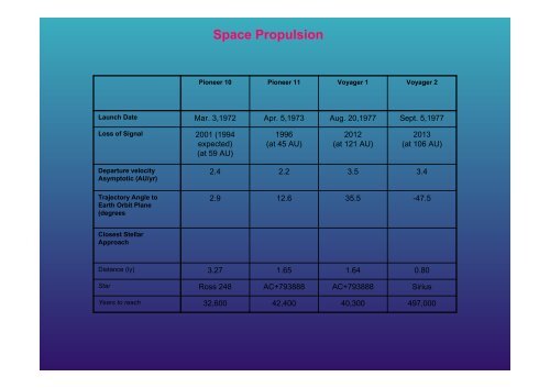
<strong>Space</strong> <strong>Propulsion</strong><br />
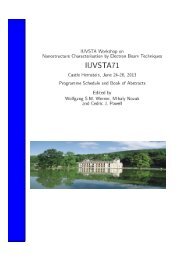
Pioneer 10<br />
Pioneer 11<br />
Voyager 1<br />
Voyager 2<br />
Launch Date<br />
Mar. 3,1972<br />
Apr. 5,1973<br />
Aug. 20,1977<br />
Sept. 5,1977<br />
Loss of Signal<br />
2001 (1994<br />
expected)<br />
(at 59 AU)<br />
1996<br />
(at 45 AU)<br />
2012<br />
(at 121 AU)<br />
2013<br />
(at 106 AU)<br />
Departure veIocity<br />
Asymptotic (AU/yr)<br />
2.4<br />
2.2<br />
3.5<br />
3.4<br />
Trajectory Angle to<br />
Earth Orbit Plane<br />
(degrees<br />
2.9<br />
12.6<br />
35.5<br />
-47.5<br />
Closest Stellar<br />
Approach<br />
Distance (ly)<br />
3.27<br />
1.65<br />
1.64<br />
0.80<br />
Star<br />
Ross 248<br />
AC+793888<br />
AC+793888<br />
Sirius<br />
Years to reach<br />
32,600<br />
42,400<br />
40,300<br />
497,000
<strong>Space</strong> <strong>Propulsion</strong>
<strong>Space</strong> <strong>Propulsion</strong>
<strong>Space</strong> <strong>Propulsion</strong><br />
1.<br />
2.<br />
3.<br />
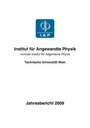
Every body continues in its state of rest or of uniform motion in a<br />
straight line except insofar as it is compelled to change that state by an<br />
external impressed force<br />
The rate of change of momentum of the body is proportional to the<br />
impressed force and takes place in the direction in which the force acts.<br />
To every action there is an equal and opposite reaction<br />
,<br />
dp / dt = F
<strong>Space</strong> <strong>Propulsion</strong><br />
Every particle of matter attracts every other particle of matter with a force<br />
directly proportional to the product of the masses and inversely<br />
proportional to the square of the distance between them.<br />
r<br />
F<br />
= −G<br />
m1m<br />
2<br />
r<br />
2<br />
r<br />
e r<br />
U ( r)<br />
=<br />
−G<br />
M<br />
r
<strong>Space</strong> <strong>Propulsion</strong><br />
1.<br />
2.<br />
3.<br />
The planets move in ellipses with the sun at one focus<br />
Areas swept out by the radius vector from the sun to a planet in equal<br />
times are equal<br />
The square of the period of revolution is proportional to the cube of the<br />
semimajor axis.<br />
That is, T 2 = const x a 3
<strong>Space</strong> <strong>Propulsion</strong><br />
Circular orbit<br />
mV =<br />
r<br />
r<br />
2<br />
GmM<br />
2<br />
r<br />
V<br />
=<br />
μ<br />
3<br />
2rπ<br />
r<br />
P = = 2π<br />
V μ
<strong>Space</strong> <strong>Propulsion</strong>
<strong>Space</strong> <strong>Propulsion</strong><br />
5<br />
3.98x10<br />
V orb<br />
≅ = 7.69<br />
3<br />
R 6.73x10<br />
[ km/<br />
s]<br />
V rot<br />
=<br />
= μ ]<br />
2πR<br />
24x3600<br />
≅ 0.489<br />
[ km/<br />
s<br />
V1 = Vorb<br />
− Vrot<br />
≅ 7.20 [ km / s]
<strong>Space</strong> <strong>Propulsion</strong><br />
Gravitational trajectories<br />
H = r ×<br />
mV<br />
angular momentum<br />
around point C<br />
d H<br />
dt<br />
⎛<br />
= m⎜<br />
⎝<br />
dr<br />
dt<br />
× V<br />
+ r ×<br />
dV<br />
dt<br />
⎞<br />
⎟<br />
= r × m<br />
⎠<br />
dV<br />
dt<br />
= r × F<br />
= M<br />
M … torque around C<br />
Assumption:<br />
Central force: F II r<br />
d H<br />
dt<br />
r × F = M = 0<br />
= M = 0<br />
H = mr × V =<br />
const.<br />
→ trajectory remains in same plane perp. to H
<strong>Space</strong> <strong>Propulsion</strong><br />
Gravitational trajectories<br />
h = H / m = r × V = rV sinφ<br />
= const specific angular momentum = const<br />
( V sinφ. dt) r<br />
d θ = /<br />
1 1<br />
dA ≅ r.<br />
.<br />
2 2<br />
( rdθ ) = rV sinφ<br />
dt<br />
dθ<br />
V sinφ<br />
= =<br />
dt r<br />
h<br />
2<br />
r<br />
dA<br />
dt<br />
=<br />
1<br />
2<br />
rV sinφ<br />
=<br />
h<br />
2<br />
= const<br />
2 nd Kepler‘s law: areal<br />
velocity is constant<br />
Plane trajectories and constant areal velocity follow from<br />
central force requirement only; force field must not be<br />
1/r 2 and not even conservative
<strong>Space</strong> <strong>Propulsion</strong><br />
Gravitational trajectories<br />
Assumption: conservative 1/r 2 force field<br />
F<br />
= −<br />
dU<br />
dr<br />
mμ<br />
= −<br />
2<br />
r<br />
V<br />
2<br />
2<br />
μ<br />
− = ε = const.<br />
r<br />
conservation of total energy; ε is specific total<br />
energy;<br />
V<br />
2<br />
⎛<br />
= ⎜<br />
⎝<br />
dr<br />
dt<br />
2<br />
⎞<br />
⎟<br />
⎠<br />
⎛<br />
+ ⎜r<br />
⎝<br />
2<br />
dθ<br />
⎞<br />
⎟<br />
dt ⎠<br />
magnitude 2 of velocity in polar coordinates (r, θ)<br />
μ<br />
− +<br />
r<br />
1<br />
2<br />
⎛<br />
⎜<br />
⎝<br />
dr<br />
dt<br />
2<br />
⎞<br />
⎟<br />
⎠<br />
+<br />
2<br />
1 ⎛ dθ<br />
⎞<br />
⎜r<br />
⎟<br />
2 ⎝ dt ⎠<br />
= ε<br />
2<br />
2 2<br />
h ⎛ dr ⎞ h 2μ<br />
differential equ. of<br />
⎜ ⎟ + − = ε<br />
4<br />
2<br />
r ⎝ dθ<br />
⎠ r r<br />
trajectory<br />
dr<br />
dt<br />
dr dθ<br />
dr ⎛ h<br />
= ⎜<br />
dθ<br />
dt dθ<br />
⎝ r<br />
=<br />
2<br />
⎞<br />
⎟<br />
⎠<br />
dθ<br />
V sinφ<br />
= =<br />
dt r<br />
h<br />
2<br />
r<br />
dθ<br />
=<br />
h / r<br />
2<br />
2μ<br />
h<br />
ε + −<br />
r r<br />
2<br />
2<br />
dr<br />
subst.<br />
r=1/u<br />
dθ<br />
= −<br />
h<br />
ε + 2μ.<br />
u − h<br />
2<br />
u<br />
2<br />
du<br />
θ + C<br />
= −h<br />
∫<br />
du<br />
2<br />
ε + 2μ.<br />
u − h u<br />
2<br />
general solution
<strong>Space</strong> <strong>Propulsion</strong><br />
Gravitational trajectories<br />
θ + C<br />
= −h<br />
∫<br />
du<br />
2<br />
ε + 2μ.<br />
u − h u<br />
2<br />
r = 1/u<br />
r<br />
=<br />
1−<br />
1+<br />
h<br />
2<br />
2ε.<br />
h<br />
2<br />
μ<br />
/ μ<br />
2<br />
.cos<br />
( θ + C)<br />
when θ is counted from minimum r,<br />
then cos = -1<br />
From geometry:<br />
p<br />
r =<br />
1+ ε cosθ<br />
Is equation of conical section in<br />
polar coordinates (r,θ) when origin<br />
is in focal point; p is parameter and<br />
ε numerical excentricity of conic<br />
section;<br />
ε > 1 …hyperbola<br />
ε = 1 …parabola<br />
ε < 1 …ellipse<br />
ε = 0 … circle<br />
r<br />
=<br />
1+<br />
1+<br />
h<br />
2<br />
/ μ<br />
2ε.<br />
h<br />
2<br />
μ<br />
2<br />
.cosθ<br />
Trajectories under influence of gravity of<br />
the sun are conical sections with the sun<br />
in one focal point<br />
1 st Kepler
<strong>Space</strong> <strong>Propulsion</strong><br />
Gravitational trajectories<br />
r<br />
=<br />
1+<br />
1+<br />
h<br />
2<br />
/ μ<br />
2ε.<br />
h<br />
2<br />
μ<br />
2<br />
.cosθ<br />
ε > 1 → specific<br />
ε = 1 → specific<br />
ε < 1 → specific<br />
energy<br />
energy<br />
energy<br />
ε > 0 → hyperbola<br />
ε = 0 → parabola<br />
ε < 0 → ellipse<br />
numerical excentricity ε<br />
of conical section<br />
p =<br />
2<br />
h<br />
μ<br />
ε =<br />
1+<br />
2ε.<br />
h<br />
2<br />
μ<br />
2<br />
parameter, semimajor axis and num.<br />
excentricity of trajectory follow from kinetic<br />
and dynamic parameters by analogy of anal.<br />
solution with geometry of conical sections<br />
from<br />
geometry<br />
p<br />
a =<br />
2<br />
1−<br />
ε<br />
a<br />
μ<br />
= −<br />
2ε<br />
all trajectories with same semimajor axis have<br />
same (specific) total energy
<strong>Space</strong> <strong>Propulsion</strong><br />
dA 2<br />
2<br />
P = abπ = πa<br />
1−<br />
ε = πa<br />
2<br />
dt<br />
p<br />
a<br />
In case of closed trajectory ( ellipse) product<br />
of constant areal velocity and period is equal<br />
to area of ellipse<br />
from kinetics:<br />
dA/dt = h/2<br />
p =<br />
2<br />
h<br />
μ<br />
2<br />
b = a 1−<br />
ε p = a( 1−<br />
ε ) 2<br />
from analyt. geometry<br />
2 4<br />
2<br />
2 4π<br />
a p 4π<br />
a<br />
P = =<br />
2<br />
h a μ<br />
3<br />
3 rd Kepler<br />
But also: period of elliptical trajectory only<br />
dependent on semimajor axis
<strong>Space</strong> <strong>Propulsion</strong><br />
r<br />
=<br />
1+<br />
1+<br />
h<br />
2<br />
/ μ<br />
2ε<br />
. h<br />
2<br />
μ<br />
2<br />
.cosθ<br />
a<br />
μ<br />
= −<br />
2ε<br />
ε =<br />
2ε.<br />
h<br />
1+<br />
2<br />
μ<br />
2<br />
2<br />
p = h / μ<br />
geometric parameters of orbit can<br />
be derived from kinetic parameters<br />
of motion<br />
specific<br />
energy<br />
ε > 0 → hyperbola<br />
specific<br />
energy<br />
ε = 0 →<br />
parabola<br />
specific<br />
energy<br />
ε < 0 → ellipse<br />
type of conics dependent<br />
on total energy
<strong>Space</strong> <strong>Propulsion</strong><br />
The orbit of a body is completely determined, when we know at a given point<br />
- the radius – vector from the central body<br />
- the velocity vector<br />
Or, equivalently r, V and included angle α
1<br />
2<br />
3<br />
4<br />
5<br />
6<br />
7<br />
8<br />
9<br />
Evaluate μ = GM Sun<br />
<strong>Space</strong> <strong>Propulsion</strong><br />
The total energy per mass of the orbit is constant so by<br />
evaluating the kinetic and gravitational potentialenergy at<br />
one point in the orbit (EQ 10) we obtain<br />
The energy per mass of the spacecraft determines the<br />
orbits semi-major axis (EQ 11):<br />
This then gives the circular velocity of the orbit (EQ 3)<br />
The period of the orbit is given by Kepler's third law:<br />
The areal velocity is know from the initial conditions<br />
(velocity and position) of the spacecraft; α being the angle<br />
between radiusvector and S/C direction<br />
The other method of determining areal velocity gives us the<br />
eccentricity of the orbit, by taking the ellipse area as Aell =<br />
πa2(1-e2)1/2<br />
We now know the size and shape of the orbit and can<br />
determine the extent of the orbit from (EQ 16) and (EQ 18)<br />
The final parameter is the true anomaly as determined by<br />
the angle the craft is from perihelion of the new orbit (see<br />
ellipse equation in Section 2.3.1)<br />
2<br />
E V GM<br />
= −<br />
m 2 r<br />
GM<br />
a = −<br />
2<br />
v<br />
c<br />
=<br />
3/ 2<br />
⎛ a ⎞<br />
P = P<br />
⎜<br />
⎟<br />
earth<br />
⎝ aearth<br />
⎠<br />
1 A = r . V .sinα<br />
2<br />
A<br />
A =<br />
P<br />
GM<br />
a<br />
ell<br />
sun<br />
( E / m)<br />
sun<br />
πa<br />
=<br />
2<br />
⎛ AP ⎞<br />
ε = 1 − ⎜ 2 ⎟<br />
⎝ a π ⎠<br />
r p<br />
= a( 1 − ε )<br />
r a<br />
= a( 1 + ε )<br />
2<br />
1−<br />
ε<br />
P<br />
2 ⎞<br />
( 1−<br />
ε ) − ⎟<br />
⎠<br />
1 ⎛ a<br />
cos Θ = ⎜ 1<br />
ε ⎝ r<br />
2<br />
sun
<strong>Space</strong> <strong>Propulsion</strong><br />
Elliptical orbits passing through same point with identical<br />
velocities into different directions
<strong>Space</strong> <strong>Propulsion</strong><br />
Reaction propulsion<br />
momentum conservation<br />
mV = const.<br />
dp<br />
= d( mV ) = mdV + Vdm = 0<br />
dV<br />
= −V<br />
e<br />
dm<br />
m<br />
∫<br />
dV<br />
=<br />
−V<br />
e<br />
∫<br />
dm<br />
m<br />
ΔV<br />
= −V<br />
e<br />
ln<br />
m<br />
m<br />
i<br />
f<br />
Tsiolkovski equation
<strong>Space</strong> <strong>Propulsion</strong><br />
Tsiolkovsky equation<br />
ΔV<br />
= −V<br />
e<br />
ln<br />
m<br />
m<br />
i<br />
f<br />
m<br />
m<br />
i<br />
f<br />
=<br />
e<br />
ΔV<br />
−<br />
v e<br />
since direction of v e (exhaust velocity) is opposite to velocity gain ΔV, the ratio<br />
- ΔV/v e is always positive; therefore we can express the exponent as ΔV/ Iv e I<br />
m<br />
m<br />
i<br />
f<br />
= e<br />
ΔV<br />
v<br />
e<br />
• initial mass increases exponentially with ΔV (@ m f = const.)<br />
• decreases exponentially with v e<br />
• final mass, which can be brought into orbit with ΔV de-<br />
…creases with increasing ΔV and increases with v e
<strong>Space</strong> <strong>Propulsion</strong><br />
Thrust<br />
Thrust is the force propelling a rocket; it is the reaction force to the force accelerating<br />
the exhaust particles. We consider the exhaust consisting of N identical particles<br />
(gas, ions, electrons, stones,…) of mass m<br />
dP d dN<br />
•<br />
⎛ ⎞<br />
T = =<br />
.<br />
dt dt dt ⎝ ⎠<br />
•<br />
( N.<br />
p) = . p = ⎜ N m⎟Ve<br />
= m Ve<br />
•<br />
mass flow [kg/s]<br />
m<br />
V<br />
T<br />
e<br />
exhaust velocity [m/s]<br />
thrust [N]
<strong>Space</strong> <strong>Propulsion</strong><br />
Total impulse<br />
Total impulse is the total momentum gained during the burn time t b of a thruster<br />
definition<br />
I<br />
tb<br />
= ∫Tdt<br />
[ N.<br />
s]<br />
0<br />
When thrust is constant over time, or at least during thruster – on time intervals,<br />
total impulse can be written as<br />
I = T τ.<br />
τ τ<br />
τ<br />
= ⎛ dm ⎞<br />
∫Tdt<br />
= ∫ ⎜ ⎟Ve<br />
dt = Ve<br />
dt<br />
∫<br />
0 0 ⎝ ⎠<br />
0<br />
I dm = V . m<br />
e<br />
p<br />
m p … propellant mass used during mission time τ<br />
V e … exhaust velocity, assumed to be constant during mission
<strong>Space</strong> <strong>Propulsion</strong><br />
Specific impulse<br />
I sp<br />
=<br />
dp<br />
dm<br />
definition<br />
what is the momentum produced per unit of<br />
mass expelled?<br />
The higher this ratio, the higher is the velocity<br />
gain of a rocket upon exhaustion of ist fuel<br />
mass; • I sp is an important quality<br />
m<br />
parameter<br />
I sp<br />
=<br />
dp / dt<br />
dm / dt<br />
=<br />
•<br />
p<br />
=<br />
•<br />
m<br />
T<br />
•<br />
m<br />
[ m / s]<br />
•<br />
m<br />
mass flow [kg/s]<br />
I<br />
dp<br />
dm<br />
d<br />
( mV . )<br />
e<br />
sp<br />
= = =<br />
dm<br />
V<br />
e<br />
[ m / s]<br />
V e<br />
exhaust velocity, assumed to be constant
<strong>Space</strong> <strong>Propulsion</strong><br />
jet power<br />
definition<br />
P<br />
j<br />
dE<br />
=<br />
dt<br />
j<br />
=<br />
• 2<br />
mVe<br />
N<br />
2<br />
[ W ]<br />
jet power is the kinetic energy, emitted per time unit from a S/C<br />
•<br />
⎛ ⎞<br />
⎜ N mVe<br />
⎟V<br />
e<br />
P<br />
⎝ ⎠<br />
j<br />
=<br />
=<br />
2<br />
TI<br />
2<br />
sp
<strong>Space</strong> <strong>Propulsion</strong><br />
specific power<br />
P<br />
sp<br />
=<br />
P<br />
T<br />
jet<br />
[ W / N]<br />
specific power is the beam power P jet , necessary to produce a unit of thrust<br />
P<br />
•<br />
2<br />
mVe<br />
/ 2<br />
sp<br />
= =<br />
•<br />
mV<br />
e<br />
Ve<br />
2<br />
[ m/<br />
s],[<br />
W<br />
/ N]
<strong>Space</strong> <strong>Propulsion</strong><br />
these purely mechanical relationships are valid independent of<br />
the methods used to accelerate exhaust particles<br />
I<br />
•<br />
T = m.<br />
I sp<br />
I<br />
sp<br />
=<br />
τ<br />
= ∫Tdt<br />
= I<br />
0<br />
dp<br />
dm<br />
= V<br />
e<br />
sp<br />
dE<br />
j<br />
TI<br />
P<br />
j<br />
= =<br />
dt 2<br />
Pj<br />
P<br />
sp<br />
= =<br />
T<br />
m<br />
i<br />
/ m<br />
f<br />
sp<br />
I<br />
sp<br />
2<br />
= e<br />
=<br />
m<br />
sp<br />
Isp<br />
T<br />
ΔV<br />
p<br />
•<br />
m<br />
≡ Tτ<br />
( m m )<br />
ΔV<br />
= I ln /<br />
i<br />
f<br />
[N]<br />
[N.s]<br />
[W]<br />
[m/s]<br />
[W/N], [m/s]<br />
[1]<br />
thrust<br />
total impulse<br />
jet power<br />
specific impulse<br />
specific power<br />
Tsiolkovsky equ.<br />
(rocket equ.)
<strong>Space</strong> <strong>Propulsion</strong><br />
The staging principle<br />
R = /<br />
j<br />
( mi<br />
m<br />
f<br />
) j<br />
initial / final mass ratio<br />
of j th stage<br />
ΔV<br />
ΔV<br />
....<br />
1<br />
ΔV<br />
2<br />
n<br />
=<br />
=<br />
=<br />
I<br />
I<br />
I<br />
ΔV = I<br />
sp<br />
sp<br />
sp<br />
sp<br />
ln R<br />
1<br />
ln R<br />
ln R<br />
2<br />
n<br />
ln( R . R2...<br />
R<br />
velocity gains of<br />
individual stages<br />
1 n<br />
)<br />
total velocity gain<br />
(of final stage)
<strong>Space</strong> <strong>Propulsion</strong><br />
The staging principle<br />
when the rocket motors of all stages have the same specific impulse I sp ,<br />
the velocity difference of the final stage with respect to the initial velocity is<br />
ΔV = I<br />
sp<br />
ln( R . R2...<br />
R<br />
1 n<br />
)<br />
when the mass ratios of all stages are identical (R j = R)<br />
ΔV<br />
=<br />
I<br />
sp<br />
n<br />
ln( R ) =<br />
n.<br />
I<br />
sp<br />
. ln R
<strong>Space</strong> <strong>Propulsion</strong><br />
• a fixed total mass M of propellant is available for<br />
….acceleration of a payload of mass m L<br />
• compare the velocity gains, when the propellant is<br />
….consumed in a single – stage or a multi – stage rocket<br />
Assumptions:<br />
• initial / final mass ratios identical = R for all stages<br />
• mass of supporting structure in each stage is same fraction φ<br />
….of propellant mass of respective stage (φ = „tankage factor“)<br />
1. St.<br />
2. St.<br />
3. St.<br />
( + φ)<br />
mL<br />
+ m1 1<br />
R =<br />
mL<br />
+ φm1<br />
mL<br />
+<br />
R =<br />
m +<br />
R =<br />
m<br />
L<br />
L<br />
m<br />
+<br />
( m1<br />
+ m2<br />
)( 1+<br />
φ)<br />
m1( 1+<br />
φ) + φm2<br />
L<br />
+ ( m1<br />
+ m2<br />
+ m3<br />
)<br />
( m1<br />
+ m2<br />
)( 1+ φ ) + φm3<br />
m<br />
1<br />
R −1<br />
=<br />
1−φ<br />
m<br />
L<br />
( R −1)<br />
)<br />
R −1<br />
m2 =<br />
L<br />
1 φ<br />
1−φ<br />
[ m + ( + ) m1<br />
]<br />
( R −1)<br />
)<br />
R −1<br />
m3 =<br />
L<br />
1 φ +<br />
1−<br />
φ<br />
[ m + ( + )( m1<br />
m2<br />
)]<br />
( R −1)<br />
R −1<br />
ρ =<br />
1−φ<br />
( R −1)<br />
ψ = ( 1+ φ)ρ<br />
m<br />
i<br />
= ρmL<br />
+ ψ . Si−1<br />
propellant mass for i th stage;<br />
S i<br />
… sum of propellant masses m 1<br />
,<br />
m 2<br />
, …, m i
<strong>Space</strong> <strong>Propulsion</strong><br />
m<br />
i<br />
= ρmL<br />
+ ψ . Si−1<br />
S<br />
S<br />
S<br />
S<br />
1<br />
2<br />
3<br />
4<br />
= ρm<br />
= m<br />
= m<br />
= m<br />
2<br />
3<br />
4<br />
L<br />
+ S<br />
+ S<br />
1<br />
2<br />
+ S<br />
3<br />
= ρm<br />
= ρm<br />
L<br />
= ρm<br />
L<br />
L<br />
+ ψS<br />
1<br />
+ ψS<br />
+ ψS<br />
2<br />
3<br />
+ S<br />
1<br />
+ S<br />
+ S<br />
2<br />
3<br />
= ρm<br />
L<br />
= ρm<br />
= ρm<br />
L<br />
L<br />
+<br />
+<br />
+<br />
( 1+<br />
ψ ) S1<br />
= ρmL[ 1+<br />
( 1+<br />
ψ )]<br />
2<br />
( 1+<br />
ψ ) S2<br />
= ρmL[ 1+<br />
( 1+<br />
ψ ) + ( 1+<br />
ψ ) ]<br />
2<br />
( 1+<br />
ψ ) S = ρm<br />
1+<br />
( 1+<br />
ψ ) + ( 1+<br />
ψ ) + ( 1+<br />
ψ )<br />
3<br />
L<br />
3<br />
[ ]<br />
S<br />
n<br />
n<br />
( 1+<br />
ψ ) −1<br />
( 1+<br />
ψ )<br />
n<br />
−<br />
= ρ ∑ − 1<br />
i<br />
1<br />
mL<br />
( 1+<br />
ψ ) = ρmL<br />
= mL<br />
ψ<br />
1+<br />
φ<br />
0<br />
n<br />
total propellant mass for n<br />
stages with equal tankage factor<br />
φ and equal initial / final mass<br />
ratio R<br />
In an n – stage rocket, velocity gain in each stage is<br />
ΔV<br />
i<br />
=<br />
I<br />
sp<br />
ln R<br />
and total velocity gain of n stages is<br />
ΔV<br />
=<br />
nΔV<br />
i<br />
=<br />
nI<br />
sp<br />
ln R
<strong>Space</strong> <strong>Propulsion</strong><br />
Single- and multi – stage<br />
rockets using the same<br />
amount of propellant to<br />
accelerate same payload<br />
ΔV<br />
= I<br />
= I<br />
sp<br />
sp<br />
⎡<br />
.ln⎢<br />
⎣<br />
( 1+<br />
φ)<br />
m<br />
L<br />
⎡ 1+<br />
φ<br />
.ln⎢<br />
⎣φ<br />
+<br />
S<br />
n<br />
+ m<br />
+ φS<br />
( 1+<br />
ψ )<br />
n<br />
−n<br />
L<br />
⎤<br />
⎥<br />
⎦<br />
⎤<br />
⎥<br />
⎦<br />
=<br />
Δ V<br />
=<br />
S n<br />
= m L<br />
n . I . ln sp<br />
( 1+<br />
ψ )<br />
n<br />
R<br />
−1<br />
1+<br />
φ
<strong>Space</strong> <strong>Propulsion</strong><br />
Check<br />
for tankage factor φ 0, we have rockets consisting of payload<br />
and fuel only and single- and „multistage“ rockets with same<br />
payload and fuel masses must have the same ΔV<br />
R −1<br />
ρ = → R −1<br />
1−<br />
φ<br />
( R −1)<br />
( 1+<br />
φ ) ρ → −1<br />
ψ = R<br />
ΔV<br />
sin gle<br />
=<br />
I<br />
sp<br />
⎡ 1+<br />
φ<br />
.ln⎢<br />
⎣φ<br />
+<br />
( 1+<br />
ψ )<br />
⎤<br />
⎡ 1<br />
⎢<br />
⎣ R<br />
n ⎥ → I<br />
sp<br />
ln = nI<br />
n sp<br />
ln( R)<br />
− −<br />
⎦<br />
⎤<br />
⎥<br />
⎦<br />
=<br />
ΔV<br />
multi
<strong>Space</strong> <strong>Propulsion</strong><br />
Mission Design and Attitude Control<br />
Task<br />
Mission design<br />
Orbit changes<br />
Plane changes<br />
Orbit trim<br />
Stationkeeping<br />
Repositioning<br />
Attitude Control<br />
Thrust vector control<br />
Attitude control<br />
Attitude changes<br />
Reaction wheel unloading<br />
Maneuvering<br />
(Translational velocity change)<br />
Convert one orbit to another<br />
Change orbital plane, other orbit<br />
parameters remaining constant<br />
Remove Iaunch vehicle errors<br />
Maintain constellation position<br />
Change constellation position<br />
(RotationaI velocity change)<br />
Remove vector errors<br />
Maintain an attitude<br />
Change attitudes<br />
Description<br />
Remove stored momentum<br />
Repositioning the spacecraft axes
<strong>Space</strong> <strong>Propulsion</strong><br />
coplanar orbit changes<br />
changing a circular orbit to a<br />
coplanar elliptical orbit<br />
generalised coplanar<br />
maneuvre<br />
ΔV<br />
2<br />
= V<br />
2<br />
i<br />
+ V<br />
2<br />
f<br />
− 2V<br />
V<br />
i<br />
f<br />
cosα<br />
ΔV is smallest when this<br />
term is largest cosα = 1<br />
<br />
<br />
the transfer can be made at any intersection of two orbits.<br />
the least velocity change is necessary when the orbits are tangent and α is<br />
zero
<strong>Space</strong> <strong>Propulsion</strong><br />
Fuel consumption for orbital maneuvre with total velocity change ΔV<br />
Tsiolkovsky:<br />
m / m<br />
i<br />
f<br />
=<br />
e<br />
ΔV<br />
Isp<br />
required fuel mass:<br />
m<br />
p<br />
= m<br />
i<br />
− m<br />
f<br />
= m<br />
i<br />
⎡ ⎛<br />
⎢1<br />
− exp⎜−<br />
⎢<br />
⎣ ⎝<br />
ΔV<br />
I<br />
sp<br />
⎞⎤<br />
⎟<br />
⎥<br />
⎠⎥⎦<br />
m<br />
p<br />
⎡ ⎛ ⎞ ⎤<br />
⎢ ⎜<br />
ΔV<br />
= m ⎟<br />
f<br />
exp −1⎥<br />
⎢<br />
⎣ ⎝ I<br />
sp ⎠ ⎥⎦
<strong>Space</strong> <strong>Propulsion</strong><br />
Example 1: Simple Coplanar Orbit Change<br />
Consider an initially circular low Earth orbit at 300-km altitude. What velocity increase<br />
would be required to produce an elliptical orbit 300 x 3000 km in altitude? What would be the<br />
fuel consumption for a 750 kg (empty) S/C if I sp<br />
= 3100 m/s ?<br />
The gravity parameter of Earth is μ=398,600.4 km 3 /s 2<br />
Radius of Earth is ≈ R = 6387 km<br />
velocity on initial circular orbit:<br />
semimajor axis of final elliptical orbit:<br />
V 398,600.4<br />
= μ =<br />
= 7.726 km s<br />
r (300 + 6378.14)<br />
/<br />
ra<br />
+ rp<br />
a =<br />
2<br />
(300+<br />
6378) + (3000+<br />
6378)<br />
=<br />
= 8028<br />
2<br />
[ km]<br />
velocity at periapsis of final orbit:<br />
velocity change =<br />
V 2μ<br />
μ 2(398,600) 398,600<br />
= − =<br />
− = 8.350 km s<br />
p<br />
r a 6678 8028<br />
/<br />
ΔV = Vp −V<br />
= 8 .350 − 7.726 = 0.624 km / s<br />
fuel consumption<br />
⎡ ⎛ V ⎞ ⎤ ⎧ ⎡ (624) ⎤ ⎫<br />
mp m<br />
f ⎢exp ⎜<br />
Δ<br />
=<br />
⎟ −1⎥<br />
= 750⎨exp<br />
−1⎬<br />
= 167. 2<br />
I<br />
⎢<br />
sp ⎩ (3100)<br />
⎥<br />
⎢<br />
⎣ ⎝ ⎠ ⎥⎦<br />
⎣ ⎦ ⎭<br />
kg<br />
Velocity changes, made at periapsis, change apoapsis radius but not periapsis radius, and vice<br />
versa; the radius at which the velocity is changed remains unchanged. As you would expect, the<br />
plane of the orbit in inertial space does not change as velocity along the orbit is changed. Orbital<br />
changes are a reversible process.
<strong>Space</strong> <strong>Propulsion</strong><br />
finite burn losses<br />
thrust vector is held inertially fixed during the burn<br />
orbital elements change continuously during burn<br />
angle between thrust and velocity increases during burn<br />
at constant thrust, acceleration in flight direction decreases during burn
<strong>Space</strong> <strong>Propulsion</strong><br />
Hohmann transfer: minimum energy transfer<br />
between circular orbits<br />
orbit circularisation<br />
transfer orbit insertion<br />
V<br />
=<br />
μ<br />
r<br />
r f > r i<br />
V f < V i<br />
nevertheless all maneuvers<br />
are accelerating<br />
transfer orbit:<br />
periapsis radius = radius of initial orbit<br />
apoapsis radius = radius of final orbit
<strong>Space</strong> <strong>Propulsion</strong><br />
Example 3: Hohman transfer from circular Earth orbit (altitude = 200 km) to geostationary<br />
orbit (r = 42219 km); what is fuel consumption to bring a 1 t payload to GEO with a specific<br />
impulse of 3100 [m/s]?<br />
Velocity in LEO:<br />
Velocity in LEO:<br />
398,600<br />
V = μ =<br />
=<br />
r 6387 + 200<br />
7.78<br />
[ km / s]<br />
Velocity in GEO similarly is<br />
3.07 [km/s]<br />
Semimajor axis of transfer ellipse is<br />
( 6387 + 200)<br />
+ 42219<br />
a =<br />
=<br />
2<br />
24403<br />
[ km]<br />
Perigee velocity in transfer ellipse is:<br />
V<br />
p<br />
=<br />
2μ<br />
μ<br />
− =<br />
r a<br />
p<br />
2*398600<br />
−<br />
6387 + 200<br />
398600<br />
24403<br />
=<br />
= 10.22<br />
[ km / s]<br />
Example 3, cont‘d
<strong>Space</strong> <strong>Propulsion</strong><br />
Velocity increase in transfer orbit insertion:<br />
ΔV i<br />
= 10.22<br />
− 7.78 = 2.44 [ km / s]<br />
μ<br />
Apogee velocity in transfer ellipse is 2 2*398600 398600<br />
Va = − =<br />
− = 1.60 [ km / s]<br />
r a 42219 24403<br />
a<br />
μ<br />
Velocity increase at circularization:<br />
ΔV circ<br />
= 3.07<br />
−1.60<br />
= 1.47 [ km / s]<br />
Adding up to a total velocity increase of<br />
ΔV tot<br />
= 2.44<br />
+ 1.47 = 3.91 [ km / s]<br />
Fuel consumption is:<br />
⎡ ⎛ V ⎞ ⎤ ⎧ ⎡(3910)<br />
⎤ ⎫<br />
m<br />
p<br />
m<br />
f ⎢exp⎜<br />
Δ<br />
=<br />
⎟ −1⎥<br />
= 1000⎨exp<br />
−1⎬<br />
= 2530<br />
I<br />
⎢<br />
sp<br />
⎩ (3100)<br />
⎥<br />
⎢<br />
⎣ ⎝ ⎠ ⎥⎦<br />
⎣ ⎦ ⎭<br />
[ kg]<br />
The efficiency of the Hohmann transfer comes from the fact that the two<br />
velocity changes are made at points of tangency between the trajectories.
<strong>Space</strong> <strong>Propulsion</strong><br />
plane change<br />
maneuver<br />
ΔV =<br />
2<br />
V i<br />
α<br />
sin<br />
2<br />
without velocity change<br />
Plane changes are expensive on a propellant basis.<br />
A 10-deg plane change in low Earth orbit would.require a velocity change of about 1.4 km/s.<br />
For a 500 kg spacecraft, this plane change would require 292 kg of propellant, if one assumes an I sp of 3100 m/s<br />
The equation shows that it is important to change planes through the<br />
smallest possible angle and at the lowest possible velocity.<br />
The lowest possible velocity occurs at the longest radius, that is, at apoapsis.
<strong>Space</strong> <strong>Propulsion</strong><br />
Combined maneuver: ΔV 1-2<br />
= 1.831 km/s<br />
For separate maneuvers,<br />
plane change maneuver: ΔV 1<br />
= 0.791 km/s;<br />
circularization maneuver: ΔV 2<br />
= 1.469 km/s; total ΔV = 2.260 km/s.
<strong>Space</strong> <strong>Propulsion</strong><br />
Example 5: Repositioning<br />
Consider a geosynchronous 1t spacecraft that is required to reposition by 2-deg, counter to the<br />
velocity vector (westward), in a maneuvering time of one sidereal day (one orbit). What is the<br />
fuel consumption for that maneuver, assuming an Isp of 3100 m/s?<br />
Δφ<br />
S/C moves in reposition ellipse<br />
„placeholder“ S/C orbits in GEO<br />
example 5, cont‘d
Repositioning, cont‘d<br />
<strong>Space</strong> <strong>Propulsion</strong><br />
The elements of a geosynchronous orbit are<br />
r =<br />
42,164.17 km (circular)<br />
P =<br />
86,164.09 s<br />
V =<br />
3.07466 km/s<br />
ΔP is equal to the time required for 2 deg<br />
of motion on a geosynchronous orbit<br />
0<br />
Δϕ<br />
2 *86,164.09<br />
ΔP = P =<br />
=<br />
360 360<br />
478.689<br />
[ s]<br />
The period for the spacecraft on the<br />
elliptical reposition orbit is<br />
semimajor axis of the reposition orbit<br />
P = 86,164.09 + 478.689 = 86,642.78 [s]<br />
2<br />
2<br />
P μ (86,642.78) (398,600)<br />
a = 3 = 3<br />
= 42,320<br />
2<br />
2<br />
4π<br />
4π<br />
[ km]<br />
velocity at periapsis of an elliptical orbit<br />
with semimajor axis a<br />
V 2μ<br />
μ 2(398,600) 398,600<br />
= − =<br />
− 3.08032<br />
r a 42164 42320<br />
=<br />
[ km / s]<br />
velocity change to place the spacecraft<br />
on the reposition ellipse<br />
3.08032km/s - 3.07466km/s = 5.66 m/s<br />
The same velocity change (in the opposite direction<br />
is necessary for recirculation of repositioning orbit<br />
Propellant consumption under<br />
assumption of negligible mass change<br />
⎡ ⎛ V ⎞ ⎤ ⎧ ⎡11.32⎤<br />
⎫<br />
m<br />
p<br />
m<br />
f ⎢exp⎜<br />
Δ<br />
=<br />
⎟ −1⎥<br />
= 1000⎨exp<br />
−1⎬<br />
= 3.66<br />
I<br />
⎢<br />
sp<br />
⎩ ⎣ 3100 ⎥<br />
⎢<br />
⎣ ⎝ ⎠ ⎥⎦<br />
⎦ ⎭<br />
[ kg]
<strong>Space</strong> <strong>Propulsion</strong><br />
Gravity assist maneuvre (slingshot)<br />
S/C may gain velocity in the sun – fixed system when<br />
passing close to a planet
<strong>Space</strong> <strong>Propulsion</strong><br />
Basically a 3 – body problem; approximation possible, when m
<strong>Space</strong> <strong>Propulsion</strong><br />
M<br />
P<br />
2<br />
2<br />
/ rSOI<br />
≅ M<br />
S<br />
/ rP<br />
r ≈ r M / M<br />
SOI<br />
P<br />
P<br />
S
<strong>Space</strong> <strong>Propulsion</strong><br />
vectorial velocity addition<br />
at transfer between<br />
helocentric and<br />
planetocentric motions
<strong>Space</strong> <strong>Propulsion</strong><br />
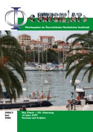
Gravity assist at Jupiter<br />
v P<br />
= 13.1 km/s<br />
passage behind planet<br />
passage in front of planet<br />
gravity assist at Jupiter can boost S/C velocity to hyperbolic orbit so that it can<br />
leave solar system (ΔV > (2 1/2 -1) v P = 5.4 km/s)
<strong>Space</strong> <strong>Propulsion</strong>
<strong>Space</strong> <strong>Propulsion</strong><br />
Maximum energy gain in gravity assist at different planets<br />
(closest approach = r P<br />
)<br />
Planetary<br />
velocity<br />
[km/s]<br />
Mass<br />
[kg]<br />
Solar<br />
distance<br />
[10 6 km]<br />
SOI<br />
radius<br />
[10 6 km]<br />
Equatorial<br />
radius<br />
[km]<br />
v 3,extr<br />
[km/s]<br />
ΔV<br />
[km/s]<br />
Mercury<br />
47.87<br />
3.28E23<br />
57.9<br />
0.024<br />
2493<br />
2.99<br />
11.96<br />
5<br />
Venus<br />
35.02<br />
4.87E24<br />
108.2<br />
0.169<br />
6051<br />
7.33<br />
16.03<br />
2<br />
Earth<br />
29.78<br />
5.97E24<br />
149.6<br />
0.259<br />
6378<br />
7.90<br />
15.33<br />
4<br />
Mars<br />
24.13<br />
6.42E23<br />
228.0<br />
0.130<br />
3394<br />
3.55<br />
9.27<br />
8<br />
Jupiter<br />
13.06<br />
1.90E27<br />
778.4<br />
24.05<br />
71400<br />
42.1<br />
23.45<br />
1<br />
Saturn<br />
9.65<br />
5.69E26<br />
1425.5<br />
24.10<br />
60000<br />
25.2<br />
15.59<br />
3<br />
Uranus<br />
6.80<br />
8.68E25<br />
2870.4<br />
18.96<br />
25650<br />
15.0<br />
10.10<br />
6<br />
Neptune<br />
5.43<br />
1.03E26<br />
4501.1<br />
32.38<br />
24780<br />
16.7<br />
9.54<br />
7<br />
Pluto<br />
4.7<br />
1.27E22<br />
5900<br />
0.47<br />
1150<br />
0.86<br />
2.00<br />
9
<strong>Space</strong> <strong>Propulsion</strong><br />
CASSINI probe to Saturn and Titan<br />
total ΔV [km/s]<br />
flight time [y]<br />
Hohmann transfer<br />
15.7<br />
6<br />
gravity assists<br />
2<br />
6.7
<strong>Space</strong> <strong>Propulsion</strong><br />
Liftoff from ground<br />
2<br />
v<br />
2<br />
μ<br />
− = ε = const.<br />
r<br />
ε<br />
gr<br />
= ε<br />
p<br />
μ<br />
= −<br />
R<br />
energy conservation<br />
ε = E/m … specific energy<br />
specific energy at rest on Earth‘s surface<br />
v = 0, r = R (purely potential energy)<br />
V<br />
=<br />
μ<br />
R<br />
velocity in circular orbit with<br />
Radius R<br />
ε =<br />
0, k<br />
μ<br />
2R<br />
spec. kinetic energy in circular orbit<br />
at Earth‘s surface, r =a = R<br />
ε<br />
O<br />
μ μ<br />
= − =<br />
2R<br />
R<br />
μ<br />
−<br />
2R<br />
total specific energy in orbit near<br />
Earth‘s surface<br />
μ ⎛ μ ⎞<br />
Δ ε<br />
O = − − ⎜ − ⎟ =<br />
2R<br />
⎝ R ⎠<br />
μ<br />
2R<br />
spec. energy for liftoff from rest into<br />
circular orbit near Earth‘s surface<br />
5<br />
μ 3.98x10<br />
ΔV = 2Δε<br />
O<br />
= =<br />
≅ 7.69<br />
3<br />
R 6.73x10<br />
[ km / s]<br />
ΔV necessary for liftoff into<br />
circular orbit near Earth‘s surface
<strong>Space</strong> <strong>Propulsion</strong><br />
Liftoff from ground<br />
5<br />
μ 3.98x10<br />
ΔV = 2Δε<br />
O<br />
= =<br />
≅ 7.69<br />
3<br />
R 6.73x10<br />
[ km / s]<br />
⎡ ⎛ V ⎞ ⎤ ⎧ ⎡(7690)<br />
⎤ ⎫<br />
mp m<br />
f ⎢exp⎜<br />
Δ<br />
=<br />
⎟ −1⎥<br />
= 1⎨exp<br />
−1⎬<br />
= 10.95<br />
I<br />
⎢<br />
sp ⎩ (3100)<br />
⎥<br />
⎢<br />
⎣ ⎝ ⎠ ⎥⎦<br />
⎣ ⎦ ⎭<br />
[ kg / kg]
<strong>Space</strong> <strong>Propulsion</strong><br />
Spiraling up<br />
ΔV, propellant consumption and mission time can be estimated when<br />
• thrust direction is always tangential to trajectory (permanent attitude change!!)<br />
• thrust
<strong>Space</strong> <strong>Propulsion</strong><br />
Spiraling up<br />
dv<br />
dt<br />
=<br />
T<br />
m<br />
+<br />
g<br />
equation of motion for S/C of mass m,<br />
propelled by thrust T<br />
r<br />
r<br />
2<br />
v<br />
ε = +U 2<br />
() r<br />
∞<br />
∞<br />
FG<br />
() ( r) dU<br />
U r = −∫<br />
dr = −∫<br />
g( r)<br />
dr = − g( r)<br />
m<br />
dr<br />
⎤ dv dU<br />
() ( r) dr ⎛ ⎞<br />
⎥ = + = ⎜<br />
dv<br />
r v<br />
v − g() ⎟<br />
⎡ 2<br />
dε<br />
d v<br />
= ⎢ + U<br />
r<br />
dt dt ⎢ 2 ⎥ dt dt ⎜<br />
⎣ ⎦ dr ⎝ dt<br />
⎠<br />
Specific energy = spec. kinetic energy +<br />
+ potential<br />
potential energy and its gradient<br />
time derivative of specific energy<br />
dε<br />
=<br />
dt<br />
T<br />
v<br />
m<br />
=<br />
T<br />
v<br />
m<br />
acc. to assumption, always v II T; inner<br />
product replaced by magnitudes
<strong>Space</strong> <strong>Propulsion</strong><br />
Spiraling up<br />
dε<br />
=<br />
dt<br />
T<br />
v<br />
m<br />
=<br />
T<br />
v<br />
m<br />
at every moment, trajectories closely resemble circles (acc. to assumption T 0)<br />
v<br />
≅<br />
μ<br />
r<br />
ε ≅<br />
−<br />
μ<br />
2r<br />
ε = −<br />
μ<br />
2a<br />
dε<br />
dt<br />
dε<br />
dr<br />
= +<br />
dr dt<br />
=<br />
2<br />
μ dr<br />
2r<br />
dt<br />
=<br />
T<br />
v<br />
m<br />
≈<br />
μ T<br />
r m<br />
ΔV<br />
=<br />
t<br />
∫<br />
t0<br />
T<br />
m<br />
dt<br />
=<br />
r<br />
∫<br />
μ dr<br />
2 r<br />
= −<br />
μ.<br />
3/ 2<br />
r0 r r 0 0<br />
1<br />
r<br />
=<br />
μ<br />
−<br />
r<br />
μ<br />
r<br />
Δ<br />
V = v c , 0<br />
− v c , r<br />
thrusting ΔV is equal to difference<br />
of velocities in initial and final orbit
<strong>Space</strong> <strong>Propulsion</strong><br />
Spiraling up<br />
time required to spiral up from r 0 to r<br />
assumption: T = const.<br />
•<br />
m = T / I dm/dt = const. •<br />
( )<br />
sp<br />
m = m0 − m t − t 0<br />
ΔV<br />
=<br />
t<br />
∫<br />
t0<br />
T<br />
m<br />
dt =<br />
T<br />
m<br />
0<br />
t<br />
∫<br />
t0<br />
m<br />
1−<br />
m<br />
dt<br />
•<br />
( t − t0<br />
)<br />
0<br />
⎡<br />
T<br />
⎢<br />
m<br />
= − ln 1−<br />
•<br />
m<br />
⎢ m0<br />
⎣<br />
⎤<br />
•<br />
( t − t0<br />
)<br />
⎥ ⎥ ⎦<br />
Δ V<br />
=<br />
μ −<br />
r<br />
0<br />
μ =<br />
r<br />
μ ⎛<br />
⎜1<br />
−<br />
r<br />
0 ⎝<br />
r<br />
0<br />
r<br />
⎞<br />
⎟<br />
⎠<br />
τ =<br />
t<br />
− t<br />
0<br />
=<br />
m<br />
•<br />
⎤⎫<br />
μ ⎞<br />
⎟<br />
m<br />
⎥⎪<br />
⎠ ⎦⎪<br />
⎭<br />
0<br />
sp<br />
1 exp<br />
m<br />
• ⎨ − −<br />
⎬ =<br />
0<br />
−<br />
⎢ ⎜<br />
−<br />
r0<br />
r ⎟ T ⎥ T<br />
m<br />
⎧<br />
⎪<br />
⎪<br />
⎩<br />
⎡<br />
⎢<br />
⎣<br />
⎛<br />
⎜<br />
⎝<br />
μ<br />
I<br />
−( vc,0<br />
−vc,1<br />
)/<br />
Isp<br />
[ 1 e ]
<strong>Space</strong> <strong>Propulsion</strong><br />
Spiraling up<br />
Δ<br />
V = v c , 0<br />
− v c , r<br />
ΔV<br />
v<br />
c,0<br />
= 1−<br />
r<br />
0<br />
r<br />
I sp<br />
>> ΔV<br />
τ =<br />
m<br />
0<br />
I<br />
sp<br />
T<br />
I<br />
−ΔV<br />
/ Isp<br />
sp ΔV<br />
/ Isp<br />
[ 1−<br />
e ] = m ( e −1)<br />
f<br />
T<br />
→<br />
m<br />
f<br />
ΔV<br />
T<br />
m<br />
p<br />
⎡ ⎛ V ⎞ ⎤<br />
m<br />
f ⎢ ⎜<br />
Δ<br />
= exp ⎟ −1⎥<br />
→ m<br />
⎢<br />
⎣<br />
I<br />
⎝ sp ⎠ ⎥⎦<br />
f<br />
ΔV<br />
I<br />
sp<br />
m<br />
∞<br />
= 100.<br />
5<br />
10<br />
100<br />
5x10<br />
τ ∞<br />
=<br />
−3<br />
5<br />
7809<br />
( e 1) 2 /10 − ≅ 11.7 [ kg]<br />
5<br />
7809<br />
( e 1) 2 /10 − ≅ 5.1 [ y]<br />
Example<br />
Electric propulsion: T = 5 mN, I sp<br />
= 10 5 m/s;<br />
Time and propellant mass required for spiraling<br />
up a 100 kg payload from 300 km LEO (v =<br />
7730 m/s) to escape velocity?
<strong>Space</strong> <strong>Propulsion</strong><br />
Comparison of Hohmann and spiral transfer<br />
Hohmann<br />
spiral<br />
Δ<br />
V H<br />
⎛<br />
= ⎜<br />
⎝<br />
2μ<br />
2μ<br />
−<br />
r r + r<br />
1<br />
1<br />
2<br />
−<br />
μ ⎞ ⎛<br />
⎟ + ⎜<br />
r<br />
1 ⎠ ⎝<br />
μ<br />
−<br />
r<br />
2<br />
2μ<br />
2μ<br />
−<br />
r r + r<br />
2<br />
1<br />
2<br />
⎞<br />
⎟<br />
⎠<br />
ΔV<br />
= V 1<br />
−V 2<br />
ρ = r 2<br />
/r 1<br />
Δ<br />
V H<br />
V 1<br />
⎛<br />
= ⎜<br />
⎝<br />
2ρ<br />
⎞<br />
−1⎟<br />
+<br />
1+<br />
ρ ⎠<br />
1 ⎛<br />
⎜<br />
1−<br />
ρ ⎝<br />
2 ⎞<br />
⎟<br />
1+<br />
ρ<br />
⎠<br />
ΔV<br />
V<br />
1<br />
= 1−<br />
1<br />
ρ
<strong>Space</strong> <strong>Propulsion</strong><br />
Comparison of Hohmann and spiral transfer<br />
( 1+<br />
ρ)<br />
3<br />
3<br />
1 a r1<br />
τ H<br />
= P tr<br />
= π = π<br />
2 μ 8μ<br />
depending only on orbital radii<br />
3<br />
τ<br />
SP<br />
→ m<br />
f<br />
⎟ f = 1<br />
T T r 1<br />
⎜<br />
⎝ ρ ⎠<br />
= dr2<br />
T r1<br />
r<br />
.r2<br />
dτ = m<br />
f<br />
μ<br />
also depending on S/C mass, thrust<br />
(and specific impulse)<br />
V<br />
ΔV<br />
m<br />
μ ⎛<br />
⎜ −<br />
1<br />
⎞
<strong>Space</strong> <strong>Propulsion</strong><br />
Attitude maneuvres<br />
3 – axis controlled S/C
<strong>Space</strong> <strong>Propulsion</strong><br />
Thruster combinations to produce control forces and moments (HYPER, 2003)<br />
Option 1<br />
Four clusters, each with 3 thrusters, are located at the corners of the S/C<br />
on opposite diagonals:<br />
group {1, 2, 3, 4} is pointing into +/- X<br />
group {11, 12, 13, 14} into +/- Y<br />
group {21, 22, 23, 24} into +/- Z.
<strong>Space</strong> <strong>Propulsion</strong><br />
Thruster combinations to produce control forces and moments (HYPER, 2003)<br />
Option 2
<strong>Space</strong> <strong>Propulsion</strong>
<strong>Space</strong> <strong>Propulsion</strong><br />
Attitude control thrusters on spin – stabilised S/C
<strong>Space</strong> <strong>Propulsion</strong><br />
Kinetics for rotational motion of S/C<br />
ω<br />
α =<br />
rotational motion<br />
T = torque [N.m]<br />
Θ = angle of rotation of the<br />
spacecraft [rad]<br />
= angular velocity of the<br />
spacecraft [rad/s]<br />
angular acceleration of the<br />
spacecraft during a firing,<br />
[rad/s 2 ]<br />
Lin. analogon<br />
F = force [N]<br />
s = path [m]<br />
v = velocity [m/s]<br />
a = acceleration<br />
[m/s 2 ]<br />
rotational motion<br />
1<br />
αt b<br />
2<br />
a<br />
s =<br />
2 t<br />
2<br />
Θ =<br />
2<br />
α =<br />
T<br />
I v<br />
ω = αt b<br />
Lin. analogon<br />
a =<br />
v =<br />
F<br />
m<br />
at<br />
I v<br />
=<br />
mass moment of inertia of<br />
the vehicle, [kg.m 2 ]<br />
m = mass [kg]<br />
H =<br />
I v ω<br />
p =<br />
mv<br />
t b<br />
= duration of the burn [s]<br />
H = change of spacecraft<br />
angular momentum during<br />
the firing, [kg.m 2 /s]<br />
t = time [s]<br />
p = momentum<br />
[m/s]<br />
H = Tt b<br />
p ∫ Fdt ≅<br />
= Ft
<strong>Space</strong> <strong>Propulsion</strong><br />
Kinetics for rotational motion of S/C<br />
Linear analogon<br />
torque, produced by n thrusters, mounted at torque arm L,<br />
firing with equal thrust F<br />
T = nFL<br />
F<br />
during the burn, the angular acceleration of the spacecraft is<br />
α =<br />
nFL<br />
I v<br />
a =<br />
F<br />
m<br />
at shut down, the vehicle will have turned by 2<br />
nFLtb<br />
2<br />
at shutdown, the spacecraft is left rotating at angular velocity<br />
Θ =<br />
ω =<br />
2I<br />
v<br />
v<br />
nFL<br />
I<br />
t<br />
b<br />
a<br />
s =<br />
2 t<br />
v = a.<br />
t<br />
angular momentum produced by a single firing is p =<br />
H = Tt b<br />
∫ Fdt<br />
propellant consumed during the burn is<br />
nFt<br />
b<br />
m<br />
p<br />
= =<br />
I<br />
sp<br />
H<br />
LI<br />
sp<br />
•<br />
= F m<br />
I sp<br />
/
<strong>Space</strong> <strong>Propulsion</strong><br />
nFt<br />
b<br />
m<br />
p<br />
= =<br />
I<br />
sp<br />
H<br />
LI<br />
sp<br />
shows the advantage of a long moment arm. The maximum moment<br />
arm is constrained in a surprising way: by the inside diameter of the<br />
launch vehicle payload fairing<br />
Launch vehicle Fairing i.d.[ft]<br />
Atlas 9.6 or 12<br />
Delta 8.3 or 10<br />
<strong>Space</strong> Shuttle 15<br />
Titan ll 10<br />
Titan III 13.1<br />
Titan IV 16.7
<strong>Space</strong> <strong>Propulsion</strong><br />
one – axis maneuvre
1 – axis maneuvre, cont‘d<br />
<strong>Space</strong> <strong>Propulsion</strong><br />
total angle of rotation is<br />
rotation during coasting is<br />
Θ m<br />
= Θ (accelerating) + Θ (coasting) + Θ (braking)<br />
Θ = ωtc<br />
the coasting rotation angle is<br />
Θ =<br />
nFL<br />
t<br />
I<br />
v<br />
b<br />
t<br />
c<br />
ω =<br />
nFL<br />
I<br />
v<br />
t<br />
b<br />
total rotation during acceleration, coasting and braking is<br />
Θ<br />
m<br />
⎛ nFL<br />
= 2<br />
⎜ t<br />
⎝ 2I<br />
v<br />
2<br />
b<br />
⎞ nFL<br />
⎟ + t<br />
⎠ I<br />
v<br />
b<br />
t<br />
c<br />
=<br />
nFL<br />
I<br />
v<br />
2<br />
( 2t<br />
+ t t )<br />
b<br />
b<br />
c<br />
Θ =<br />
nFLt<br />
2I<br />
v<br />
2<br />
b<br />
maneuver time is<br />
t m = t C + 2t b<br />
accel.<br />
minimum rotation time is a fully powered<br />
maneuver with zero coast time<br />
t<br />
min<br />
= 2t<br />
b<br />
=<br />
2. Θ<br />
m<br />
I<br />
nFL<br />
v<br />
thrust level required for each thruster<br />
at given minimum rotation time<br />
F<br />
Θ m v<br />
2<br />
min<br />
I<br />
= 2<br />
nLt<br />
propellant required for a one-axis<br />
maneuver is twice the single burn consumption<br />
m<br />
p<br />
nFt<br />
b<br />
= 2 =<br />
I<br />
sp<br />
nFt<br />
I<br />
sp<br />
min<br />
nFt<br />
b<br />
m<br />
p<br />
= =<br />
I<br />
sp<br />
H<br />
LI<br />
sp
<strong>Space</strong> <strong>Propulsion</strong><br />
Example 6: One-Axis Maneuver<br />
Find the minimum time required for a spacecraft to perform a 90-deg turn about the z axis<br />
with two thrusters if the spacecraft has the following characteristics:<br />
Mass of S/C = 500 kg,<br />
Radius of S/C = 0.75 m<br />
Moment of inertia about the z axis ≅(2/5)M S/C.<br />
L 2 = 112.5 kg.m 2<br />
Moment arm = 0.75 m<br />
Thrust of each engine = 10 N<br />
and<br />
Θ m<br />
= π/2 = 1.5708 rad<br />
t<br />
2. Θ<br />
I<br />
m v<br />
min<br />
= =<br />
=<br />
nFL<br />
2*1.5708*112.5<br />
2*10*0.75<br />
4.854<br />
s<br />
How much propellant was consumed by the maneuver if I sp<br />
= 1900 m/s ?<br />
nFt<br />
m 2 * 2 *10 * 4.854<br />
m<br />
p<br />
= 2 =<br />
= 0. 102<br />
I 1900<br />
sp<br />
kg
<strong>Space</strong> <strong>Propulsion</strong><br />
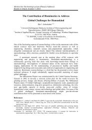
precession of spin axis<br />
H i … initial angular momentum<br />
H a … applied angular momentum<br />
Φ / 2 ≈<br />
H<br />
a =<br />
H<br />
i<br />
nFLtb<br />
I yω<br />
nutation angle caused by<br />
application of single thrust pulse<br />
Two pulses are required to precess the spin axis; both pulses are parallel to the spin axis. After the<br />
First pulse, the spin axis will continue to precess until a second pulse of equal magnitude and opposite<br />
direction is fired. The spin axis can be repositioned by selecting the timing of the second pulse.<br />
The first pulse is used to cause nutation at an angle of one-half the desired precession. The second<br />
pulse stops the nutation and provides the remaining half of the desired angle
<strong>Space</strong> <strong>Propulsion</strong><br />
Example 7: Precession of Spin Axis<br />
What burn time, or pulse width, is required to precess a spacecraft spin axis by 3-deg (0.05236 rad)<br />
under the following conditions:<br />
Thrust 10 N<br />
Moment arm = 0.5 m<br />
Moment of inertia 112.5 kg.m2<br />
<strong>Space</strong>craft Spin rate 2 rpm (0.2094 rad/s)<br />
Specific impulse = 1900 m/s<br />
t<br />
ΦIvω<br />
=<br />
2nFL<br />
0.05236*112.5*0.2094<br />
2*1*10*0.5<br />
b<br />
=<br />
=<br />
0.124<br />
[ s]<br />
burn time of thruster to produce nutation<br />
angle Φ/2<br />
m<br />
nFtb<br />
2*1*10*0.124<br />
= 2 =<br />
= 0.0013 [ kg]<br />
1.3 [ g]<br />
total propellant consumed by both burns<br />
I 1900<br />
p<br />
=<br />
sp
<strong>Space</strong> <strong>Propulsion</strong><br />
limit cycle without external torque<br />
A limit cycle without external torque swings the spacecraft back and forth between preset<br />
angular limits. When the spacecraft drifts across one of the angular limits Θ L , the attitude-control<br />
system fires a thruster pair for correction. The spacecraft rotation reverses and continues until the<br />
opposite angular limit is reached, at which time the opposite thruster pair is fired. It is important<br />
that the smallest possible impulse be used for the corrections because the impulse must be<br />
removed by the opposite thruster pair.<br />
cont‘d
limit cycle cont‘d<br />
<strong>Space</strong> <strong>Propulsion</strong><br />
nFL<br />
Θ = t<br />
I<br />
v<br />
t<br />
b c<br />
Θ<br />
tot<br />
=<br />
nFL<br />
I<br />
v<br />
2<br />
⎛ Pw<br />
⎜<br />
⎝ 2<br />
tcP<br />
+<br />
2<br />
w<br />
⎞<br />
⎟<br />
⎠<br />
total angle of rotation Θ ↓ replacing 2t b<br />
P w<br />
(EQ 86)<br />
Θ<br />
L<br />
=<br />
1<br />
2<br />
nFL<br />
I<br />
v<br />
t<br />
b<br />
t<br />
c<br />
=<br />
nFL<br />
4I<br />
v<br />
P<br />
w<br />
t<br />
c<br />
the limit settings + Θ L are one-half of the coasting angle ↓<br />
Θ = 2 Θ L<br />
(neglecting small rotations during accel & brake)<br />
nFP<br />
mp, cyc<br />
= 2<br />
I<br />
sp<br />
w<br />
each cycle includes two pulses;<br />
the propellant consumed per cycle is<br />
Propellant consumption is small for low thrust, short burn time, and high specific impulse<br />
in pulsing operation. Pulsing engines are characterized by minimum impulse bit I min<br />
I min = (F.P w ) min<br />
The minimum impulse bit is a characteristic of a given thruster/valve combination<br />
cont‘d
limit cycle cont‘d<br />
<strong>Space</strong> <strong>Propulsion</strong><br />
pulsing properties of attitude – control thrusters<br />
Cold-gas -Helium<br />
500<br />
CoId-gas-Nitrogen 50<br />
5 - 10<br />
N 2<br />
H 4<br />
Monopropellant -<br />
500<br />
50 - 100 1200<br />
Bipropellant -<br />
N 2<br />
O 4<br />
/MMH<br />
Min thrust<br />
[mN]<br />
50<br />
10000<br />
Min impulse bit<br />
[mN.s]<br />
5 - 10<br />
750 - 1500<br />
Pulsing<br />
I sp<br />
[m/s]<br />
800<br />
1200<br />
nFL<br />
ω = t<br />
I<br />
v<br />
b<br />
t<br />
c<br />
I<br />
vΘ<br />
= 4<br />
nFLP<br />
L<br />
w<br />
coast time through 2Θ L<br />
4I<br />
Θ<br />
v L<br />
tcy<br />
= tc<br />
+ 2PW<br />
= + 2<br />
nLI<br />
min<br />
P<br />
w<br />
length of a cycle (from +Θ L to -Θ L ) if minimum impulse bits<br />
are used; usually, P W can be neglected<br />
nFP<br />
mp, cyc<br />
= 2<br />
I<br />
sp<br />
w<br />
•<br />
m p<br />
=<br />
2 2<br />
mp, cyc n IminL<br />
~<br />
propellant consumption per unit time<br />
t 2I<br />
I Θ<br />
cy<br />
sp<br />
v<br />
L
<strong>Space</strong> <strong>Propulsion</strong><br />
Example 8: Limit-Cycle Operation<br />
A spacecraft with 112.5 kg.m 2 inertia uses 5N thruster pairs mounted at a radius of 0.5 m from<br />
the center of mass. For limit-cycle control to Θ L = 0.5 deg (0.008727 rad), what is the propellant<br />
consumption rate if I sp is 1900 m/s, the pulse duration is 30 ms, and there are no external<br />
torques. ?<br />
t<br />
4IvΘL<br />
4*112,5*0,008727<br />
= 2Pw<br />
+ = 0.06 +<br />
= 0,06 + 26,181 26,241 [ s]<br />
time for 1 cycle<br />
nFLP 2*5*0,5*0,030<br />
cy<br />
=<br />
w<br />
nFPw<br />
2*5* 0.03<br />
m<br />
p , cy<br />
= 2 = 2 = 0.00032 [ kg / cycle]<br />
= 0,32 [ g / cycle]<br />
propellant consumed per cycle<br />
I 1900<br />
sp<br />
• m<br />
p,<br />
cy 0,00032<br />
−5<br />
m<br />
p<br />
= = ≅ 1.2x10<br />
[ kg / s]<br />
= 1.037<br />
t 26,241<br />
cy<br />
[ kg / day]<br />
average propellant<br />
consumption rate
Simplified equations for external torques<br />
<strong>Space</strong> <strong>Propulsion</strong><br />
Disturbance<br />
Type<br />
Influenced<br />
primarily by<br />
Formula<br />
Gravity<br />
gradient<br />
Constant or<br />
cyclic,<br />
depending on<br />
vehicle<br />
orientation<br />
<strong>Space</strong>craft<br />
geometry, Orbit<br />
altitude<br />
3μ<br />
Tg<br />
= I z − I y Θ<br />
~ 4x10 -5 [Nm]<br />
3<br />
r<br />
where T g<br />
is the max gravity torque; µ is the Earth's gravity constant (398,600<br />
km 3 Is 2 ), r the orbit radius, Θ the max deviation of the z axis from vertical in<br />
radians;I z<br />
and I y<br />
are moments of inertia about z and y (or x, if smaller) axes.<br />
Solar radiation<br />
Constant force<br />
but cyclic on<br />
Earth-oriented<br />
vehicles<br />
<strong>Space</strong>craft<br />
geometry,<br />
<strong>Space</strong>craft surface<br />
area<br />
The worst-case solar radiation torque<br />
T<br />
sp<br />
=<br />
P<br />
A<br />
L<br />
( 1<br />
+ q<br />
) cos<br />
i<br />
s<br />
s<br />
s<br />
~ 7x10 -7 [Nm]<br />
is due to a specularly reflective surface, where P S<br />
is the solar constant, 4.617<br />
x 10 -6 N/m 2 ; A s<br />
is the area of the surface, L s<br />
the center of pressure to center<br />
of mass offset, i the angle of incidence of the sun, and q the reflectance factor<br />
that ranges from 0 to 1; q = 0.6 is a good estimate<br />
Magnetic field<br />
Cyclic<br />
Orbit altitude,<br />
Residual spacecraft<br />
magnetic dipole,<br />
Orbit inclination<br />
T m<br />
= DB<br />
where T m<br />
is the magnetic torque on the spacecraft, D the residual dipole<br />
moment of the vehicle in A.m 2 , and B the Earth's magnetic field in Tesla. B<br />
can he approximated as2M/r 3 for a polar orbit to half that at the equator. M is<br />
the magnetic moment, 8 x 10 25 emu at Earth, and r is radius from dipole<br />
(Earth) center to spacecraft in centimeters<br />
Aerodynamic<br />
Constant for<br />
Earth-oriented<br />
vehicle in<br />
circular orbit<br />
Orbit altitude,<br />
<strong>Space</strong>craft<br />
configuration<br />
T<br />
∑<br />
a<br />
= F<br />
i<br />
L<br />
i<br />
T a<br />
is the summation of the forces F i<br />
on each of the exposed surface areas<br />
times the moment arm L i<br />
to the center of each surface to the center of mass,<br />
where<br />
F = ρC d<br />
AV 2 /2<br />
with F the force, C d<br />
the drag coefficient (usually between 2.0 and 2.5), p the<br />
atmospheric density, A the surface area, and V the spacecraft velocity.
<strong>Space</strong> <strong>Propulsion</strong><br />
dir. of ext. torque<br />
one-sided limit cycle<br />
with an external torque on the spacecraft,<br />
rotation occurs until a limit line is reached<br />
and a thruster pair is fired for correction<br />
total angular momentum H supplied by the<br />
propulsion system exactly equals the momentum<br />
induced by the external torque T x during mission<br />
time t m ; F is time – averaged thrust<br />
H = T t =<br />
x<br />
m<br />
Ft<br />
m<br />
propellant mass required to compensate for the<br />
external torque<br />
nF<br />
I<br />
nFL<br />
m p = tm<br />
= tm<br />
=<br />
sp<br />
LI<br />
sp<br />
T<br />
LI<br />
x<br />
sp<br />
t<br />
m<br />
cont‘d
One sided limit cycle, ct‘d<br />
<strong>Space</strong> <strong>Propulsion</strong><br />
S/C rotation is accelerated by from zero speed at the extreme limit +Θ L (point 1) through an angular path<br />
of < 2ΘL with an angular acceleration α x , generated by the external torque only. The opposite<br />
limit angle will be reached after an angular interval 2Θ L and a “pass” time t p (approximately equal to<br />
half the cycle time t cy ).<br />
Θ<br />
1<br />
=<br />
2<br />
2<br />
2<br />
L<br />
α<br />
x p<br />
t<br />
t<br />
cy<br />
Θ<br />
L<br />
= ~ 2t<br />
p<br />
= 4 = 4<br />
α<br />
x<br />
ΘLI<br />
T<br />
x<br />
v<br />
angular speed ω L , at the end of the cycle, at – Θ L (at point 2) is<br />
ω<br />
L<br />
= α t / 2 = 2<br />
x<br />
cy<br />
T<br />
x<br />
I<br />
Θ<br />
v<br />
L<br />
Now the thrusters are firing, producing a thrusting angular<br />
acceleration α. They reduce this angular speed to 0<br />
(at the turning point 3) after a burning time of P W /2<br />
ω<br />
L<br />
= α. P / 2 =<br />
W<br />
nLFP<br />
2I<br />
v<br />
W<br />
From that follows the impulse per thruster, required to turn<br />
around the angular speed of the S/C, so that it moves against<br />
external torque up to an angle of not larger than Θ L<br />
FP<br />
W<br />
≤ 4<br />
nL<br />
T<br />
x<br />
I<br />
v<br />
Θ<br />
L<br />
If minimum impulse bits I min are used, the rotation limit must be<br />
wider than a minimum Θ L , in order to avoid thrusters being fired<br />
in the direction of external torque. This would cause excessive<br />
propellant consumption.<br />
Θ<br />
L<br />
><br />
2 2 2<br />
n L I<br />
16I<br />
T<br />
v<br />
min<br />
x
<strong>Space</strong> <strong>Propulsion</strong><br />
forced limit cycle<br />
A forced limit cycle occurs when thrusters are<br />
fired in the direction of the external torque; that<br />
is, when the condition<br />
Θ<br />
L<br />
><br />
n<br />
2<br />
L<br />
2<br />
16I<br />
v<br />
I<br />
2<br />
min<br />
T<br />
x<br />
is not met<br />
propellant consumed in a forced limit cycle is<br />
m<br />
p<br />
=<br />
IvR<br />
LΘ<br />
I<br />
2 R [Hz] = 1/t cy = limit-cycle rate<br />
tm<br />
of the system<br />
t<br />
L sp<br />
m [s] = mission duration<br />
R can only be calculated numerically from a higher order equation containing the parameters<br />
I min<br />
, P W<br />
, T x<br />
, I v<br />
, L, Θ L<br />
.
<strong>Space</strong> <strong>Propulsion</strong><br />
reaction wheel maneuvres<br />
To perform a rotational maneuver with a reaction wheel, the flywheel is accelerated<br />
by a motor. The spacecraft accelerates in the opposite direction.<br />
cont’d
eaction wheel, cont’d<br />
<strong>Space</strong> <strong>Propulsion</strong><br />
A S/C can be rotated by an angle Θ by application<br />
of a torque T for time interval t<br />
Θ =<br />
Tt<br />
2<br />
2<br />
I v<br />
this torque can be supplied by an accelerating flywheel;<br />
angular acceleration α W<br />
is supplied by a motor<br />
T α w I w<br />
=<br />
v<br />
The resulting S/C rotation angle is<br />
and the increase in wheel speed:<br />
αW<br />
I<br />
Θ =<br />
2I<br />
W<br />
t<br />
2<br />
Δω<br />
w<br />
= α w<br />
t<br />
The S/C can be returned to its original position by applying the opposite torque to the flywheel;<br />
the net increase in flywheel rotational speed then is 0 (neglecting friction). Due to unbalanced torques<br />
however, the flywheel eventually will reach its upper angular speed limit and then is not fully<br />
available for maneuvering any more. To become maneuverable again it must be „unloaded“, i.e.<br />
its angular speed must be brought to 0 again.<br />
cont’d
eaction wheel, cont’d<br />
<strong>Space</strong> <strong>Propulsion</strong><br />
total angular momentum of a fully loaded wheel is<br />
H<br />
=<br />
I w<br />
ω<br />
w<br />
, max<br />
to unolad the wheel, a torque in the opposite direction must be<br />
applied to it by the motor for a certain time; in order not to<br />
produce net rotation of the S/C, an equal and opposite<br />
momentum must be supplied by the thrusters:<br />
H = Tt =<br />
nFLt<br />
time required for unloading is<br />
t<br />
=<br />
H<br />
nFL<br />
=<br />
I<br />
w<br />
ω<br />
w,<br />
nFL<br />
max<br />
propellant consumption for unloading is<br />
m<br />
p<br />
nF.<br />
t<br />
= .<br />
I<br />
sp<br />
L<br />
L<br />
=<br />
I<br />
wωw<br />
LI<br />
sp<br />
cont’d
eaction wheel, cont’d<br />
<strong>Space</strong> <strong>Propulsion</strong><br />
Example 9: Reaction Wheel Unloading<br />
How much propellant does it take to unload one of the Magellan wheels, and<br />
how long does it take? (JPL Venus Mission, 1994)<br />
The Magellan wheel characteristics are:<br />
maximum momentum = 27 N-m-s<br />
maximum wheel speed = 4000 rpm = 418.879 rad/s<br />
The thruster pair to be used has the following characteristics:<br />
thrust = 1 N; moment arm = 2m<br />
pulsing specific impulse 1500 m/s.<br />
the propellant mass required to unload it is<br />
m<br />
H<br />
LI<br />
27<br />
=<br />
2*1500<br />
p =<br />
=<br />
sp<br />
0.009<br />
[ kg]<br />
engine burn time required to unload is<br />
H 27<br />
t = = = 6.75<br />
nFL 2*1*2<br />
[ s]