Phase Diagram for Nanostructuring CaF 2 Surfaces ... - IAP/TU Wien
Phase Diagram for Nanostructuring CaF 2 Surfaces ... - IAP/TU Wien
Phase Diagram for Nanostructuring CaF 2 Surfaces ... - IAP/TU Wien

You also want an ePaper? Increase the reach of your titles
YUMPU automatically turns print PDFs into web optimized ePapers that Google loves.
PRL 109, 117602 (2012) PHYSICAL REVIEW LETTERS<br />
week ending<br />
14 SEPTEMBER 2012<br />
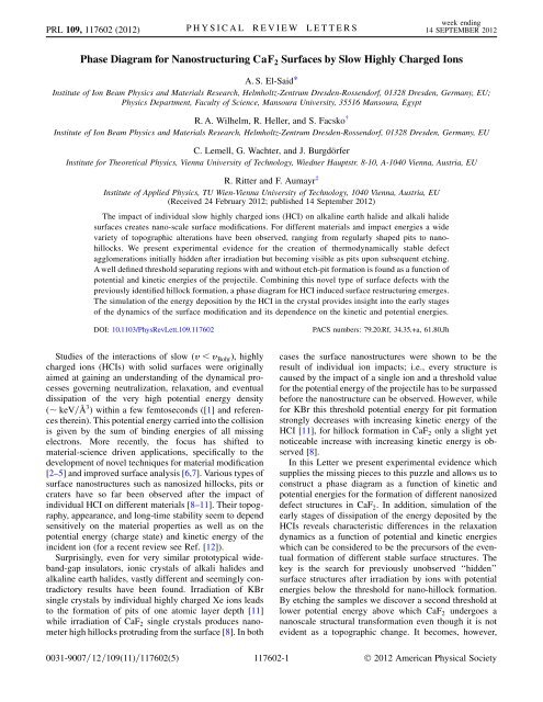
<strong>Phase</strong> <strong>Diagram</strong> <strong>for</strong> <strong>Nanostructuring</strong> <strong>CaF</strong> 2 <strong>Surfaces</strong> by Slow Highly Charged Ions<br />
A. S. El-Said*<br />
Institute of Ion Beam Physics and Materials Research, Helmholtz-Zentrum Dresden-Rossendorf, 01328 Dresden, Germany, EU;<br />
Physics Department, Faculty of Science, Mansoura University, 35516 Mansoura, Egypt<br />
R. A. Wilhelm, R. Heller, and S. Facsko †<br />
Institute of Ion Beam Physics and Materials Research, Helmholtz-Zentrum Dresden-Rossendorf, 01328 Dresden, Germany, EU<br />
C. Lemell, G. Wachter, and J. Burgdörfer<br />
Institute <strong>for</strong> Theoretical Physics, Vienna University of Technology, Wiedner Hauptstr. 8-10, A-1040 Vienna, Austria, EU<br />
R. Ritter and F. Aumayr ‡<br />
Institute of Applied Physics, <strong>TU</strong> <strong>Wien</strong>-Vienna University of Technology, 1040 Vienna, Austria, EU<br />
(Received 24 February 2012; published 14 September 2012)<br />
The impact of individual slow highly charged ions (HCI) on alkaline earth halide and alkali halide<br />
surfaces creates nano-scale surface modifications. For different materials and impact energies a wide<br />
variety of topographic alterations have been observed, ranging from regularly shaped pits to nanohillocks.<br />
We present experimental evidence <strong>for</strong> the creation of thermodynamically stable defect<br />
agglomerations initially hidden after irradiation but becoming visible as pits upon subsequent etching.<br />
A well defined threshold separating regions with and without etch-pit <strong>for</strong>mation is found as a function of<br />
potential and kinetic energies of the projectile. Combining this novel type of surface defects with the<br />
previously identified hillock <strong>for</strong>mation, a phase diagram <strong>for</strong> HCI induced surface restructuring emerges.<br />
The simulation of the energy deposition by the HCI in the crystal provides insight into the early stages<br />
of the dynamics of the surface modification and its dependence on the kinetic and potential energies.<br />
DOI: 10.1103/PhysRevLett.109.117602<br />
PACS numbers: 79.20.Rf, 34.35.+a, 61.80.Jh<br />
Studies of the interactions of slow (v
PRL 109, 117602 (2012) PHYSICAL REVIEW LETTERS<br />
week ending<br />
14 SEPTEMBER 2012<br />
visible in the <strong>for</strong>m of triangular pits after chemical etching.<br />
This threshold depends on both the potential and the kinetic<br />
energies of the HCIs closely resembling the threshold<br />
behavior found <strong>for</strong> pit <strong>for</strong>mation on KBr. Accompanying<br />
molecular dynamics simulations suggest this second<br />
threshold to be associated with lattice defect aggregation<br />
in <strong>CaF</strong> 2 following electronic excitations caused by the<br />
HCI-surface interaction.<br />
Thin platelets of <strong>CaF</strong> 2 were prepared by cleaving a high<br />
purity single-crystal block grown from melt in an inert<br />
atmosphere along the (111) plane. This cleavage is known<br />
to produce atomically flat fluorine-terminated surfaces which<br />
are ideal <strong>for</strong> observing surface topographic changes down to<br />
the nanometer scale [13]. 129 Xe qþ ions were extracted from<br />
the electron beam ion trap at the Two-Source-Facility of the<br />
Helmholtz-Zentrum Dresden-Rossendorf using an electrostatic<br />
potential of 4.5 kV. By using a two stage deceleration<br />
system and adjusting the potential difference between source<br />
and target from 4.5 kV down to 0.18 kV, highly charged Xe qþ<br />
projectiles over a wide range of charge states (10 q 33,<br />
corresponding to potential energies of 0:8 keV E pot <br />
21:2 keV) and kinetic impact energies (6 keV E kin <br />
150 keV) could be produced. The applied ion fluences<br />
were chosen between 0.5 and 5 10 8 ions=cm 2 , small<br />
enough to avoid overlapping of impact sites and high enough<br />
to obtain reasonable statistics. The time averaged current<br />
density varied between 10 4 and 3 10 5 ions=s=cm 2<br />
as derived from the ion count rate and a circular beam spot<br />
with a diameter of 6 mm. The surfaces of the irradiated<br />
samples were investigated using atomic <strong>for</strong>ce microscopy<br />
(AFM) (Veeco Multimode). The AFM was operated in contact<br />
mode with a constant loading <strong>for</strong>ce of less than 5 nN<br />
using nonconductive Si 3 N 4 sensors (Veeco Instruments) with<br />
cantilevers of <strong>for</strong>ce constants 0:1 Nm. The image processing<br />
was per<strong>for</strong>med using the WSXM software [14]. Ionirradiated<br />
<strong>CaF</strong> 2 samples were chemically etched using a<br />
HNO 3 solution (10% vol.) at room temperature without<br />
agitation [13]. Each platelet was immersed once in the<br />
etchant, subsequently in deionized water, and was finally<br />
dried in a stream of dry nitrogen. It should be emphasized<br />
that we use much shorter etching times t e than applied<br />
in standard etching techniques. For the latter, typically<br />
t e * 1 minute yields etch pits even starting from randomly<br />
occurring atomic-scale dislocations and much of the sensitivity<br />
to hidden defect aggregates would be lost. Due to the<br />
dramatically enhanced etching speed in regions with a high<br />
defect density caused by the HCIs ( 20 nm=s compared to<br />
a regular lateral etching speed of less than 3nm=s [13]), t e ¼<br />
10 s turned out to be the optimum etching time combining<br />
good visibility of etch pits in AFM while selecting only<br />
defect clusters created by HCI impact. The presented structures<br />
with dimensions in the range of a few 100 nm in lateral<br />
and vertical direction are by far larger than the topographic<br />
resolution of the ambient AFM in contact mode.<br />
The observation of a pattern of well-defined irradiated<br />
and masked areas (Fig. 1) <strong>for</strong> 150 keV Xe 33þ ion impact on<br />
FIG. 1 (color online). AFM topographic image (50 50 m 2 )<br />
of a <strong>CaF</strong> 2 surface showing etch pits after exposure to 150 keV<br />
Xe 33þ ions. The sample was irradiated through a mask (indicated<br />
by dotted lines) and subsequently chemically etched using<br />
HNO 3 . The inset in the upper left corner shows a magnification<br />
of the etch pits (1:5 1:5 m 2 ).<br />
<strong>CaF</strong> 2 (111) is direct evidence of HCI induced surface<br />
defects which can be clearly distinguished from randomly<br />
occurring dislocations and surface damage. In irradiated<br />
areas, etch pits of regularly structured 3-faced symmetric<br />
triangular depressions appear which are similar to those<br />
observed after irradiation and etching of BaF 2 [15]. This<br />
particular geometrical shape originates from the (111)<br />
crystal lattice orientation of the <strong>CaF</strong> 2 sample [13]. The<br />
number of pits is in good agreement with the applied ion<br />
fluence; i.e., each etch pit is created by a single ion impact.<br />
We suppose the pits are localized at the sites where HCI<br />
impact created hillocks were situated prior to etching. The<br />
charge state (q ¼ 33) of the incident ion corresponds to a<br />
potential energy well above the threshold <strong>for</strong> nanohillock<br />
<strong>for</strong>mation.<br />
Lowering the charge state to values below the potential<br />
energy threshold <strong>for</strong> hillock <strong>for</strong>mation (q th 28 <strong>for</strong> Xe;<br />
E pot ¼ 12 keV) reveals the appearance of similar pits in<br />
the absence of preceding hillocks (Fig. 2). At the same kinetic<br />
energy of E kin ¼ 40 keV <strong>for</strong> ‘‘low’’ charge states (q & 18)<br />
no damage of the etched surface is visible, whereas at<br />
a higher charge state (q ¼ 25, E pot ¼ 8:1 keV) etch pits<br />
appear.<br />
In order to investigate the influence of both potential and<br />
kinetic energies on etch pit <strong>for</strong>mation, we per<strong>for</strong>med systematic<br />
irradiations with 129 Xe qþ projectiles of different<br />
charge states (q ¼ 10 to 33) and with varying kinetic energy<br />
on <strong>CaF</strong> 2 . The resulting thermodynamically stable damage<br />
structures and modifications can be summarized by a ‘‘phase<br />
diagram’’ with potential and kinetic energies as state variables<br />
(Fig. 3). Three different phases pertaining to surface<br />
117602-2
PRL 109, 117602 (2012) PHYSICAL REVIEW LETTERS<br />
week ending<br />
14 SEPTEMBER 2012<br />
FIG. 2 (color online). Topographic contact-mode AFM images<br />
of <strong>CaF</strong> 2 (111) samples irradiated by 40 keV Xe ions in different<br />
charge states (columns): (a), (d) Xe 18þ , (b), (e) Xe 25þ , and (c),<br />
(f) Xe 33þ . In each frame an area of 1 m 1 m is displayed.<br />
Upper row: resulting images without etching (a), (b), (c). Lower<br />
row: images after etching by HNO 3 (d), (e), (f). Ion fluences<br />
were 2 10 8 ions=cm 2 <strong>for</strong> (e), (f) and 1–2 10 9 ions=cm 2 <strong>for</strong><br />
(a), (b), (c), (d).<br />
restructuring can be distinguished: the stability region A<br />
without detectable surface modification after HCI impact<br />
[Figs. 2(a) and 2(d)], region B in which defect clusters<br />
become visible as regularly shaped pits only upon etching<br />
[Figs. 2(b) and 2(e)], and the nanohillock region C [Figs. 2(c)<br />
and 2(f)] in which hillocks resulting from nanomelting can<br />
be observed after irradiation. The nanomelting arises from<br />
the transfer of high local energy density during HCI impact<br />
and is followed by a rapid quenching resulting in the<br />
<strong>for</strong>mation of a hillock-like structure (nanohillock) [8]. Pits<br />
appear in phase C only after etching presumably at the<br />
FIG. 3 (color online). Hillock and etch pit <strong>for</strong>mation on <strong>CaF</strong> 2<br />
(111) induced by irradiation with highly charged Xe ions. Full<br />
(open) green circles show pairs of potential and kinetic energies<br />
where hillocks are produced (absent) after irradiation, full (open)<br />
red triangles indicate pairs where pits are present (missing) after<br />
etching the irradiated samples.<br />
positions of the hillocks which could not be found on the<br />
etched surface.<br />
While the threshold <strong>for</strong> hillock <strong>for</strong>mation strongly depends<br />
on potential energy but only weakly on kinetic<br />
energy [8,12] implying an almost vertical boundary of<br />
region C in Fig. 3, the border separating the stability region<br />
A and the defect agglomeration region B (etch pits) is<br />
strongly dependent on both kinetic and potential energies.<br />
Ions with lower kinetic energy require more potential<br />
energy to create etchable damage than faster ones. Such<br />
synergistic effects of kinetic and potential energies have<br />
previously been observed <strong>for</strong> pit <strong>for</strong>mation in KBr [11],<br />
however, with the difference that no chemical etching was<br />
a prerequisite <strong>for</strong> the pits to be observed. This may be<br />
related to the much higher defect mobility in KBr than in<br />
<strong>CaF</strong> 2 leading to a more efficient transport of defects to the<br />
surface immediately followed by material desorption.<br />
These experimental findings suggest a scenario <strong>for</strong> nanostructure<br />
<strong>for</strong>mation on alkaline earth halides and alkali<br />
halides involving initial heating of electrons by multiple<br />
electron transfer and Auger relaxation, hot electron transport<br />
and dissipation with accompanying lattice heating by<br />
electron-optical phonon coupling, and finally atomic motion<br />
in the heated crystal which results in dislocations, defects,<br />
and structural weakening of the cooled lattice. The early<br />
stages of defect <strong>for</strong>mation can be simulated within a threestep<br />
model exploiting disparate time scales of the underlying<br />
processes: the initial electronic energy deposition of the<br />
HCIs occurring on the (sub) femtosecond time scale can<br />
be described by the classical-over-barrier model [16],<br />
the hot electron transport and lattice heating occurring on<br />
a sub-picosecond time scale by classical electron-transport<br />
simulations [17], and finally the atomic motion by a<br />
molecular-dynamics (MD) simulation which we follow <strong>for</strong><br />
up to 15 ps [18]. It should be noted that accurate potential<br />
surfaces <strong>for</strong> ionic crystals, in particular, in the presence of<br />
excitations and charge transfer entering the MD simulation,<br />
are not available. Following the system on longer time scales<br />
and reaching the regime of <strong>for</strong>mation of thermodynamically<br />
stable phases is, thus, not possible. Our simulation results<br />
can there<strong>for</strong>e provide only qualitative, yet important,<br />
insights into the early stages of defect <strong>for</strong>mation and aggregation.<br />
The following qualitative trends can be readily<br />
extracted. For HCIs in ‘‘low’’ charge states (Fig. 4, left)<br />
only a few (i.e., low density) individual defects (point<br />
defects, single vacancies) are created at or below the surface,<br />
where we take the distance individual fluorine atoms travel<br />
during 15 ps as measure <strong>for</strong> the eventual defect <strong>for</strong>mation<br />
probability. These defects either remain below the surface,<br />
easily anneal or are too small to be detected by means of<br />
AFM. Since the etchability of <strong>CaF</strong> 2 is strongly coupled to<br />
the creation of large defect aggregates [19] rather than to<br />
point defects, no pits are observed after etching. Our MD<br />
simulations do not yield any significant number of lattice<br />
displacements <strong>for</strong> low q (well below 1%).<br />
117602-3
PRL 109, 117602 (2012) PHYSICAL REVIEW LETTERS<br />
week ending<br />
14 SEPTEMBER 2012<br />
FIG. 4 (color online). Scenario <strong>for</strong> surface modification as a<br />
function of charge q or, equivalently, potential energy of the<br />
HCIs. Upper row: the charge state controls the created surface<br />
modification from nonetchable single defects (low q) to defect<br />
aggregates (medium q) and to locally molten zones (high q),<br />
schematically. Lower row: AFM images. Center row: typical<br />
results of molecular dynamics simulations showing that the<br />
initial electronic excitation of the surface and energy transfer<br />
to the lattice leads to a considerable number of displacements<br />
(center column) even be<strong>for</strong>e melting of the surface sets in<br />
(right column); center figures created using AtomEye [28].<br />
For larger q and, correspondingly, larger potential<br />
energy, the sputtering yield [20] as well as the density of<br />
defects (excitons, color centers, Ca enriched regions due to<br />
F 2 <strong>for</strong>mation) strongly increase. The latter is now large<br />
enough to lead to defect clusters and aggregates (Fig. 4,<br />
center column). Depending on their mobility, defects may<br />
diffuse to the surface, leading to defect-mediated desorption<br />
[21] and thus <strong>for</strong>m (monoatomic) pits as observed in<br />
the case of the alkali halide KBr [11]. The defect-mediated<br />
desorption mechanism is less probable in <strong>CaF</strong> 2 since color<br />
center recombination below the surface is much more<br />
likely [22] due to the small energy gain of color center<br />
pair <strong>for</strong>mation as well as the <strong>for</strong>mation of more complex<br />
(and there<strong>for</strong>e immobile) defect agglomerates [23,24]. The<br />
material in the vicinity of the impact region is not ablated<br />
but structurally weakened and <strong>for</strong>ms the nucleus of an<br />
etchable defect subsequently removed by a suitable etchant<br />
[15]. The synergistic effect induced by the accompanying<br />
kinetic energy originates from kinetically induced defects<br />
created in the collision cascade which enhance the trapping<br />
of the color centers created by potential energy [25] and<br />
there<strong>for</strong>e increases defect agglomeration. Consequently,<br />
the borderline between the regions A (stable) and B (etchable<br />
surface defects) has a negative slope in the phase diagram<br />
(Fig. 3). While our MD simulation cannot directly account<br />
<strong>for</strong> the defect cluster <strong>for</strong>mation (due to the lack of realistic<br />
binary potentials <strong>for</strong> color centers and charge-exchanged<br />
constituents), it shows in the regime of phase B atomic<br />
displacements of the order of a few percent of the impact<br />
region, the overwhelming majority of which are fluorine<br />
atoms (Fig. 4, center). This is believed to be a necessary<br />
precursor <strong>for</strong> defect aggregation.<br />
At still higher potential energies (Fig. 4, right column),<br />
heating of the lattice atoms by primary and secondary<br />
electrons from the deexcitation of the HCIs surpasses the<br />
melting threshold of the solid [8,18]. Heat and pressure<br />
de<strong>for</strong>ms the surface and after rapid quenching a hillock<br />
remains at the surface. With increasing kinetic energy, the<br />
region where the potential energy of the HCIs is deposited,<br />
extends slightly deeper into the target [8]. There<strong>for</strong>e, the<br />
kinetic energy dependence of the borderline between the<br />
region of nanohillock <strong>for</strong>mation (region C) and defect<br />
clustering without protrusion (region B) is only weak<br />
with a slightly positive slope. The overall surface damage<br />
(lattice distortion, defect aggregations) extends well beyond<br />
the molten core. While the latter determines the diameter<br />
of the hillock, the <strong>for</strong>mer determines the size of the nucleus<br />
of the etch pit. Within the MD simulations a much larger<br />
number of displacements ( 25%) is observed in region C,<br />
a significant fraction of which are calcium atoms.<br />
Even though the present scenario is demonstrated specifically<br />
<strong>for</strong> <strong>CaF</strong> 2 , we surmise that it should hold <strong>for</strong> other<br />
halide crystals as well. While borderlines between different<br />
regions A, B, andC will, of course, depend on the specific<br />
target material, we expect the phase diagram (Fig. 3) to<br />
remain qualitatively valid. For BaF 2 (111) and KBr (001),<br />
<strong>for</strong> example, we have previously observed the A and B<br />
phases [15,26]. The phase diagram predicts that by further<br />
increasing the potential energy of the HCIs we should<br />
be able to reach region C, i.e., hillock <strong>for</strong>mation (or melting)<br />
in line with first indications <strong>for</strong> hillock <strong>for</strong>mation on<br />
BaF 2 [27].<br />
In summary, we have established a phase diagram <strong>for</strong><br />
stable nanoscale surface modification of alkaline earth<br />
halides and alkali halides by highly charged ion impact<br />
with its potential and kinetic energies as control parameters.<br />
In addition to the region of predominantly potential<br />
energy driven melting and hillock <strong>for</strong>mation, a second<br />
region was identified in which a sufficient number of<br />
defects agglomerate such that chemical etchants are able<br />
to remove material leaving triangular shaped pits on the<br />
surface. The etchability of the defect cluster not only<br />
depends on the potential energy of the HCIs but also<br />
strongly on the kinetic energy of the projectile. This scenario<br />
seems to be generally applicable to other alkaline<br />
earth and alkali halide surfaces as well.<br />
A. S. E. thanks the Alexander von Humboldt Foundation<br />
<strong>for</strong> financial support. The Deutsche Forschungsgemeinschaft<br />
(DFG) is gratefully acknowledged <strong>for</strong> financial support<br />
under Project No. HE 6174/1-1. R. R. is a recipient of a<br />
DOC-fellowship of the Austrian Academy of Sciences.<br />
Support from the Austrian Science Foundation FWF under<br />
Project No. SFB-041 ViCoM and the International Max<br />
Planck Research School of Advanced Photon Science APS<br />
(G. W.) is acknowledged.<br />
117602-4
PRL 109, 117602 (2012) PHYSICAL REVIEW LETTERS<br />
week ending<br />
14 SEPTEMBER 2012<br />
*a.s.el-said@hzdr.de<br />
† s.facsko@hzdr.de<br />
‡ aumayr@iap.tuwien.ac.at<br />
[1] A. Arnau, F. Aumayr, P. M. Echenique, M. Grether, W.<br />
Heiland, J. Limburg, R. Morgenstern, P. Roncin, S.<br />
Schippers, R. Schuch, N. Stolterfoht, P. Varga, T. J. M.<br />
Zouros, and H. P. Winter, Surf. Sci. Rep. 27, 113 (1997).<br />
[2] A. V. Hamza, M. W. Newman, P. A. Thielen, H. W. H. Lee,<br />
T. Schenkel, J. W. McDonald, and D. H. Schneider, Appl.<br />
Phys. Lett. 79, 2973 (2001).<br />
[3] M. Tona, H. Watanabe, S. Takahashi, N. Nakamura, N.<br />
Yoshiyasu, M. Sakurai, T. Terui, S. Mashiko, C. Yamada,<br />
and S. Ohtani, Nucl. Instrum. Methods Phys. Res., Sect. B<br />
256, 543 (2007).<br />
[4] J. M. Pomeroy, H. Grube, A. C. Perrella, and J. Gillaspy,<br />
Appl. Phys. Lett. 91, 073506 (2007).<br />
[5] R. E. Lake, J. M. Pomeroy, H. Grube, and C. E. Sosolik,<br />
Phys. Rev. Lett. 107, 063202 (2011).<br />
[6] A. V. Hamza, T. Schenkel, A. V. Barnes, and D. H.<br />
Schneider, J. Vac. Sci. Technol. A 17, 303 (1999).<br />
[7] M. Tona, S. Takahashi, K. Nagata, N. Yoshiyasu, C.<br />
Yamada, N. Nakamura, S. Ohtani, and M. Sakurai,<br />
Appl. Phys. Lett. 87, 224102 (2005).<br />
[8] A. S. El-Said, R. Heller, W. Meissl, R. Ritter, S. Facsko, C.<br />
Lemell, B. Solleder, I. C. Gebeshuber, G. Betz, M.<br />
Toulemonde, W. Möller, J. Burgdörfer, and F. Aumayr,<br />
Phys. Rev. Lett. 100, 237601 (2008).<br />
[9] M. Tona, H. Watanabe, S. Takahashi, N. Nakamura, N.<br />
Yoshiyasu, M. Sakurai, T. Terui, S. Mashiko, C. Yamada,<br />
and S. Ohtani, Surf. Sci. 601, 723 (2007).<br />
[10] M. Tona, Y. Fujita, C. Yamada, and S. Ohtani, Phys. Rev.<br />
B 77, 155427 (2008).<br />
[11] R. Heller, S. Facsko, R. A. Wilhelm, and W. Möller, Phys.<br />
Rev. Lett. 101, 096102 (2008).<br />
[12] F. Aumayr, S. Facsko, A. S. El-Said, C. Trautmann, and M.<br />
Schleberger, J. Phys. Condens. Matter 23, 393001 (2011).<br />
[13] C. Motzer and M. Reichling, J. Appl. Phys. 105, 064309<br />
(2009).<br />
[14] I. Horcas, R. Fernandez, J. M. Gomez-Rodriguez, J.<br />
Colchero, J. Gomez-Herrero, and A. M. Baro, Rev. Sci.<br />
Instrum. 78, 013705 (2007).<br />
[15] A. S. El-Said, R. Heller, F. Aumayr, and S. Facsko, Phys.<br />
Rev. B 82, 033403 (2010).<br />
[16] J. Burgdörfer, P. Lerner, and F. W. Meyer, Phys. Rev. A 44,<br />
5674 (1991).<br />
[17] B. Solleder, C. Lemell, K. Tökesi, N. Hatcher, and J.<br />
Burgdörfer, Phys. Rev. B 76, 075115 (2007).<br />
[18] G. Wachter, Diplom thesis, <strong>TU</strong> <strong>Wien</strong>-Vienna University<br />
of Technology, 2009 (unpublished), http://www.ub.tuwien<br />
.ac.at/dipl/2009/AC07452619.pdf.<br />
[19] C. Trautmann, K. Schwartz, and O. Geiss, J. Appl. Phys.<br />
83, 3560 (1998).<br />
[20] F. Aumayr and H. P. Winter, Phil. Trans. R. Soc. A 362,77<br />
(2004).<br />
[21] G. Hayderer, M. Schmid, P. Varga, H. Winter, F. Aumayr,<br />
L. Wirtz, C. Lemell, J. Burgdörfer, L. Hagg, and C. O.<br />
Reinhold, Phys. Rev. Lett. 83, 3948 (1999).<br />
[22] R. T. Williams, Radiat. Eff. Defects Solids 109, 175<br />
(1989).<br />
[23] S. Rix, U. Natura, M. Letz, C. Felser, and L. Parthier, Proc.<br />
SPIE Int. Soc. Opt. Eng. 7504, 75040J (2009).<br />
[24] S. Rix, Ph.D. thesis, Johannes Gutenberg-University<br />
Mainz, 2011 (unpublished).<br />
[25] G. Hayderer, S. Cernusca, M. Schmid, P. Varga, H. P.<br />
Winter, F. Aumayr, D. Niemann, V. Hoffmann, N.<br />
Stolterfoht, C. Lemell, L. Wirtz, and J. Burgdörfer,<br />
Phys. Rev. Lett. 86, 3530 (2001).<br />
[26] S. Facsko, R. Heller, A. S. El-Said, W. Meissl, and F.<br />
Aumayr, J. Phys. Condens. Matter 21, 224012 (2009).<br />
[27] A. S. El-Said, R. Heller, and S. Facsko, Nucl. Instrum.<br />
Methods Phys. Res., Sect. B 269, 901 (2011).<br />
[28] J. Li, Model. Simulat. Mater. Sci. Eng. 11, 173 (2003).<br />
117602-5