Flip-Chip - I-Micronews
Flip-Chip - I-Micronews
Flip-Chip - I-Micronews

Create successful ePaper yourself
Turn your PDF publications into a flip-book with our unique Google optimized e-Paper software.
<strong>Flip</strong>-<strong>Chip</strong><br />
Understand the new requirements and technologies that are reshaping<br />
the world’s highest value semiconductor packaging platform<br />
April 2011 - Report SAMPLE<br />
FC BGA<br />
PCB<br />
© 2011<br />
Copyrights © Yole Développement SARL. All rights reserved.
Content of the full report<br />
• Scope of the report and definitions………………3<br />
• Executive summary…………………………………9<br />
• Market forecasts (2010-2016)………….………….63<br />
– Top-down analysis: 2010 <strong>Flip</strong> <strong>Chip</strong> market value<br />
and 2010-2016 forecasts…………........…………….65<br />
– Bottom-up analysis: 2010 <strong>Flip</strong> <strong>Chip</strong> industry status<br />
& wafer processing capacities……………………104<br />
• Process flow and technologies………………..127<br />
– <strong>Flip</strong>-chip package platforms……........……….…...128<br />
– Bumping technologies…………………….....…….132<br />
– Copper pillars……………………………..........….…160<br />
– Substrates………………………………………...…...194<br />
– Pick, flip and place………………………......………211<br />
– Underfilling………………………………..…………..214<br />
– Fluxing…………………………………..……….…….235<br />
– Thermal Interface Materials………………..……...239<br />
• Applications and drivers of flip-chip………….244<br />
– End-Market drivers for flip-chip<br />
• Computing / Handsets / Telecom & Network servers /<br />
Consumer / Medical / Automotive / Military & Aerospace<br />
– Application focus for:<br />
• Microprocessors (MPU’s, CPU’s)<br />
• Graphical processor units (GPU’s)<br />
• <strong>Chip</strong>sets<br />
• ASICs<br />
• FPGAs<br />
• DDR memories<br />
• Application processors (APE’s)<br />
• Baseband ICs<br />
• Transceivers<br />
• Radio Front-end modules<br />
• High power LEDs<br />
• LCD display drivers<br />
• CMOS image sensors, MEMS<br />
• DSPs<br />
• SAW + BAW filters<br />
• Costs structure, flip-chip manufacturing &<br />
assembly …………………….……..………….…..273<br />
• Supply chain analysis……………………………284<br />
• Roadmaps and perspectives……………………301<br />
• Conclusions………………………………………..307<br />
© 2011 • 2<br />
Copyrights © Yole Développement SARL. All rights reserved.
Market Status and Forecast Charts (1)<br />
• Top down analysis<br />
– 2010 <strong>Flip</strong> <strong>Chip</strong> market value<br />
– Split by main process steps (substrate,<br />
wafer bumping, assembly, test)<br />
– Split by end package type (flip chip in<br />
package versus chip on flex, chip on<br />
glass<br />
– 2010-2016 <strong>Flip</strong> <strong>Chip</strong> market value<br />
forecast<br />
– Total <strong>Flip</strong> <strong>Chip</strong>, split by main process<br />
steps<br />
– <strong>Flip</strong> <strong>Chip</strong> in Package end use type, split<br />
by main process steps<br />
– 2010-2016 <strong>Flip</strong> <strong>Chip</strong> unit forecast<br />
– Total <strong>Flip</strong> <strong>Chip</strong>, by end application area<br />
• <strong>Flip</strong> <strong>Chip</strong> in Package<br />
– by end application area<br />
– For the « Plated bumps/Rigid Organic<br />
Substrate » category<br />
– For the telecom application area, by IC<br />
type<br />
– For the Computing application area, by<br />
IC type<br />
– 2010 <strong>Flip</strong> <strong>Chip</strong> Wafer Bumping<br />
– Total <strong>Flip</strong> <strong>Chip</strong>, by IC type<br />
– <strong>Flip</strong> <strong>Chip</strong> in Package (FCiP) by IC type<br />
– 2010-2016 <strong>Flip</strong> <strong>Chip</strong> wafer forecasts<br />
• Total <strong>Flip</strong> <strong>Chip</strong><br />
– split by end use type (FCIP vs<br />
COF/COG)<br />
– Split by application area<br />
– By IC type<br />
– By bumping technology/metallurgy<br />
(lead free solder vs eutectic solder vs<br />
gold vs copper,…)<br />
– Lead free vs leaded<br />
– Solder alloys vs non solder metals<br />
• <strong>Flip</strong> <strong>Chip</strong> in Package (FCiP),<br />
– by IC type<br />
– For the Telecom application area, by IC<br />
type<br />
– For the Computing application area, by<br />
IC type<br />
© 2011 • 3<br />
Copyrights © Yole Développement SARL. All rights reserved.
Market Status and Forecast Charts (2)<br />
• Bottom-up (Wafer Bumping)<br />
– 2010 wafer bumping capacity for <strong>Flip</strong><br />
<strong>Chip</strong><br />
• Total (all technologies)<br />
– By technology (solder plus copper<br />
versus gold)<br />
– By player<br />
– By region<br />
– By wafer size<br />
• Solder plus copper bumping<br />
– By technology (solder plus copper<br />
versus gold)<br />
– By player<br />
– By region<br />
– By wafer size<br />
– Player profile (OSAT vs captive IDM vs<br />
foundry vs bumping house)<br />
distribution by wafer size<br />
• Gold bumping<br />
– By technology (solder plus copper<br />
versus gold)<br />
– By player<br />
– By region<br />
– By wafer size<br />
– Player profile (OSAT vs captive IDM vs<br />
foundry vs bumping house)<br />
distribution by wafer size<br />
– 2010 Wafer bumping value for <strong>Flip</strong><br />
<strong>Chip</strong><br />
– By player<br />
– By player profile (OSAT vs captive IDM<br />
vs foundry vs bumping house)<br />
• Bottom-up (substrates)<br />
• Rigid Organic Substrates for the <strong>Flip</strong>-<br />
<strong>Chip</strong> Market<br />
– Split by supplier<br />
– Split by region<br />
• Bottom-up (underfills)<br />
– 2010 <strong>Flip</strong> <strong>Chip</strong> & Circuit board<br />
assembly underfill materials market<br />
– 2010 <strong>Flip</strong> <strong>Chip</strong> underfill materials by<br />
Process Flows, Techniques and Uses<br />
© 2011 • 4<br />
Copyrights © Yole Développement SARL. All rights reserved.
Scope of this report<br />
in Yole’s Advanced Packaging Research<br />
PANEL / Wafer-Scale-Packaging Platforms<br />
Wafer-Level<br />
Interface / Encapsulation<br />
Wafer-Level<br />
Electrical Redistribution<br />
<strong>Flip</strong>-chip & Wafer-Level<br />
Stacking / Integration<br />
Systems<br />
with<br />
Fluidic<br />
LED &<br />
Sensors<br />
Optics<br />
MEMS &<br />
Sensors<br />
Capping<br />
WL-CSP<br />
‘Fan-in’<br />
FOWLP<br />
‘Fan-Out’<br />
Embedded IC<br />
in PCB / laminate<br />
3D IC<br />
& TSV<br />
Glass / Silicon<br />
2.5D<br />
interposers<br />
<strong>Flip</strong>-chip<br />
© 2011 • 5<br />
Copyrights © Yole Développement SARL. All rights reserved.<br />
FOCUS of<br />
this new<br />
research<br />
report!
Why this report on <strong>Flip</strong>-chip ?<br />
• This is the first report of Yole Developpement on <strong>Flip</strong>-chip technology, the<br />
world’s highest value semiconductor packaging technology:<br />
– The so-called “mid-end” infrastructure consisting in foundries for wafer-level packaging operations<br />
have developed at an unprecedented pace over the past 3 years to meet the growing demand for<br />
Wafer-Level <strong>Chip</strong>-Scale Packaging (or “fan-in WLCSP”) and wafer processing for flip-chip. These new<br />
facilities, half way between front-end foundries and regular assembly and packaging facilities, now<br />
support high volume manufacturing on large size wafers, thus permitting economies of scale.<br />
– Initially driven by high speed/high IO count computer processors , FPGA’s and ASiCs, flip-chip BGA<br />
has more recently extended its reach to mobile handsets and is becoming a leading package platform<br />
in the semiconductor industry<br />
– From a specialty package for small size ESD/EMI protection integrated devices in 2000, Wafer-Level<br />
<strong>Chip</strong>-Scale-Package has become one of the most popular packages throughout the industry in just 10<br />
years totaling 9 billion units per year and still growing at a sustained rate higher than 20%. Yole<br />
Développement issued a report fully dedicated to WLCSP (WLP 2009), as well as another one fully<br />
dedicated to the emerging embedded wafer level packages in 2010 (fan-out WLCSP and embedded<br />
chip in substrate). Yole Développement has also consistently followed up 3D wafer level packaging<br />
technologies with regular market and technology reports on 3D ICs, silicon interposers, as well as<br />
equipment and materials for 3D WLP. This report on flip-chip completes our report offer on waferlevel<br />
“mi-end” technologies.<br />
– For the first time ever, the complete wafer level packaging supply chain infrastructure is being<br />
addressed by a market research and technology analysis company, covering the industry status,<br />
technologies, markets and forecasts for fan-in and fan-out WLCSP, embedded ICs, 3D TSVs and ICs,<br />
silicon & glass interposers, and now flip-chip.<br />
© 2011 • 6<br />
Copyrights © Yole Développement SARL. All rights reserved.
Who should buy this report?<br />
• Integrated semiconductor device manufacturers and fabless semiconductor companies<br />
– Visualize the drivers and expected benefits by application of flip-chip as well as the alternative options<br />
– Benchmark the industry status of flip-chip<br />
– Identify possible partnership /or second source packaging subcontractors for your forthcoming<br />
developments<br />
• Assembly and test service companies<br />
– Benchmark the industry status of flip-chip. Evaluate your market and technology position<br />
– Screen possible new applications and technologies to support diversification strategy with flip-chip<br />
technologies<br />
• Silicon wafer foundries<br />
– Screen possible new applications and technologies to support diversification strategy in wafer bumping<br />
• Equipment and material suppliers<br />
– Understand the differentiated value of your products and technologies in this large and fast growing market<br />
– Identify new business opportunities and prospects<br />
• Electronic module makers and Original Equipment Makers<br />
– Evaluate the benefits of using flip-chip devices in your end system<br />
– Monitor different suppliers to adjust your sourcing strategy<br />
• PCB and IC substrate manufacturers<br />
– Monitor the evolution of IC packaging, assembly and test, especially linked to the emerging 3D silicon/glass<br />
interposers and other 3D silicon technologies. Evaluate opportunities and threats for the flip-chip substrate<br />
market.<br />
– Screen possible new applications and technologies to support diversification strategy with flip-chip<br />
substrates<br />
© 2011 • 7<br />
Copyrights © Yole Développement SARL. All rights reserved.
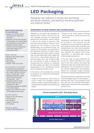
Definition of <strong>Flip</strong>-chip<br />
• A chip packaging technique in which the active area of the chip is "flipped over"<br />
facing downward. Instead of facing up and bonded to the package leads with<br />
wires from the outside edges of the chip, any surface area of the flip chip can be<br />
used for interconnection, which is typically done through metal bumps. These<br />
"bumps" are soldered onto the package and underfilled with epoxy. The flip chip<br />
allows for a large number of interconnects with shorter distances than wire, which<br />
greatly reduces inductance. (source “thefreedictionary.com”)<br />
• Metal bumps can be made of<br />
– solder (tin, or tin-lead or lead-free<br />
alloys)<br />
– copper<br />
– gold<br />
– Copper-tin or gold-tin alloys<br />
• Package substrates are<br />
– Epoxy-based (organic substrates)<br />
– Ceramic based<br />
– Copper based (leadframe substrates)<br />
– Silicon or glass based<br />
Courtesy of Amkor Technologies<br />
© 2011 • 8<br />
Copyrights © Yole Développement SARL. All rights reserved.
Foreword – This first report emphasizes on…<br />
• Even though we wanted this report to be as exhaustive as possible on all<br />
aspects of flip-chip, we decided to emphasize specifically on:<br />
– Who does what?<br />
• supply chain, flip-chip « families » of companies working together, influences, …<br />
– Markets<br />
• 2010 market shares and production levels of wafer bumping, flip-chip substrates<br />
and underfills<br />
• 2011-2016 wafer bumping market forecasts:<br />
‣ by application area (computing, telecom, industrial,…)<br />
‣ by IC type (GPU, CPU, chipset, application processor, FPGA, DDR,…)<br />
‣ by technology (bumping metallurgy, flip-chip package type)<br />
– Technologies, with a special focus on<br />
• Copper pillar bumping<br />
• Underfills<br />
Which we deem are both key to defining the next generation flip-chip<br />
technologies, especially to achieve lower costs<br />
© 2011 • 9<br />
Copyrights © Yole Développement SARL. All rights reserved.
Foreword - This Report Does Not Address/Cover ….<br />
• We chose to not address the following side topics, so as to focus on what we<br />
think is representative of « mainstream flip-chip »:<br />
– 2 nd level interconnects, since we preferred to focus on the fast evolving<br />
technologies for the 1 st level « flip-chip » interconnect and because 2 nd level<br />
interconnects are not specific to flip-chip<br />
– WLCSP, fan-in or fan-out. These technologies are the subject of separate Yole<br />
Développement reports. Even if they utilize bumping and wafer level packaging<br />
techniques like flip-chip, we consider them as separate from flip-chip as they do<br />
not use « flip-chip substrates »<br />
– Thermal Interface Materials are not covered exhaustively throughout this report:<br />
they will be addressed in the upcoming report dedicated to « power packaging and<br />
thermal management of ICs »<br />
– Silicon to silicon Micro-bumping, or « zero-level » interconnect: this part will be<br />
added to the 2012 flip-chip report, after the « 3D TSV business update » report is<br />
updated, so as to get the most accurate forecast<br />
– High Power LEDs: some of them are packaged with flip-chip, however , since this<br />
is still an emerging market with specific technologies, their study will be<br />
exhaustively carried out in our upcoming « LED Packaging report »<br />
© 2011 • 10<br />
Copyrights © Yole Développement SARL. All rights reserved.
Difference between <strong>Flip</strong>-<strong>Chip</strong> packages<br />
and the Wafer-Level <strong>Chip</strong>-Scale Package (WLCSP)<br />
• With WLCSP, the bumped integrated circuits can be directly mounted onto the Printed<br />
Circuit Board of of the end equipment by the Original Equipment Maker<br />
• <strong>Flip</strong>-<strong>Chip</strong> packages utilize an intermediate “high density interconnect” (HDI) printed<br />
circuit board<br />
• Throughout this report, we do not address WLCSP, which is the object of a dedicated<br />
market research report<br />
<strong>Flip</strong>-<strong>Chip</strong><br />
UBM<br />
Underfiller<br />
WL CSP<br />
Bump<br />
Package<br />
substrate<br />
PCB / PWB<br />
© 2011 • 11<br />
Copyrights © Yole Développement SARL. All rights reserved.
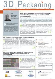
Wafer Bumping definitions<br />
WAFER BUMPING<br />
FLIP CHIP<br />
WAFER LEVEL PACKAGING<br />
<strong>Chip</strong> on Board Silicon on silicon<br />
FC BGA FC CSP FAN IN FAN OUT<br />
COF/COG micro-bumping<br />
CHIP<br />
EMBEDDING<br />
Bump<br />
characteristics<br />
Plating, screen<br />
printing<br />
pitch : <<br />
180µm<br />
Bump<br />
characteristics<br />
Plating, screen<br />
printing, stud<br />
pitch : <<br />
150µm<br />
Bump<br />
characteristics<br />
Plating<br />
pitch : <<br />
150µm<br />
Bump<br />
characteristics<br />
Plating<br />
pitch : < 60µm<br />
Bump characteristics<br />
Ball dropping<br />
pitch : 400-500µm<br />
Courtesy of Statschippac<br />
Courtesy of 3M<br />
Courtesy<br />
of SPIL<br />
Courtesy of<br />
NXP and FCI<br />
Scope of the<br />
2011 <strong>Flip</strong>-<strong>Chip</strong> report<br />
Part of the 2011<br />
3D IC market report<br />
Scope of the 2011<br />
WLCSP report<br />
Scope of the 2011<br />
fan-out/embedded report<br />
© 2011 • 12<br />
Copyrights © Yole Développement SARL. All rights reserved.
The Evolution of Semiconductor Packaging<br />
A bridging technology between ICs and PCBs<br />
Feature sizes of PCBs<br />
Feature sizes of CMOS transistors<br />
100µm<br />
Organic interposers<br />
3D integration<br />
Bumping<br />
28nm<br />
© 2011 • 13<br />
1970<br />
through<br />
hole<br />
technology<br />
1980<br />
Surface mount<br />
devices<br />
Copyrights © Yole Développement SARL. All rights reserved.<br />
1990<br />
CSPs/BGAs<br />
SiPs<br />
2000<br />
WLCSP<br />
more SiPs<br />
<strong>Flip</strong>-chip BGA<br />
PoP<br />
2010<br />
3DIC<br />
TSV<br />
Fan-out WLCSP<br />
Cu pillars<br />
Silicon interposers
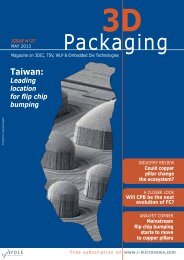
The Evolution of Semiconductor Packaging<br />
a bridging technology between ICs and PCBs<br />
• The evolution of semiconductor packaging<br />
technologies over the past 40 years had been driven<br />
by the need to bridge the increasing « IO<br />
interconnect gap », between the fast decreasing<br />
silicon geometries (Moore’s law) and the slower<br />
shrink of the Printed Circuit Board technologies<br />
Feature sizes of PCBs<br />
Feature sizes of CMOS transistors<br />
100µm<br />
• <strong>Flip</strong>-<strong>Chip</strong> emerged as the mainstream solution over<br />
the 2000-2010 decade to match the requirements of<br />
the high-IO count and high IO-density devices.<br />
Organic interposers<br />
3D integration<br />
Bumping<br />
• We estimate that because of this gap, a silicon size<br />
increase usually translates to a 3 to 4 times<br />
necessary increase of the package size for high IO<br />
density devices<br />
PCB pitch (mm)<br />
Bond pad<br />
opening/pitch<br />
(µm)<br />
28nm<br />
1970<br />
through<br />
hole<br />
technology<br />
1980<br />
Surface mount<br />
devices<br />
1990<br />
CSPs/BGAs<br />
SiPs<br />
2000<br />
WLCSP<br />
more SiPs<br />
<strong>Flip</strong>-chip BGA<br />
PoP<br />
2010<br />
3DIC<br />
TSV<br />
Fan-out WLCSP<br />
Cu pillars<br />
Silicon interposers<br />
130/100<br />
1.27<br />
1<br />
65/65<br />
45/45<br />
0.5<br />
0.4<br />
wireless<br />
© 2011 • 14<br />
2005<br />
2010<br />
Copyrights © Yole Développement SARL. All rights reserved.<br />
CMOS 130nm<br />
(2000)<br />
CMOS 40nm<br />
(2007)<br />
CMOS 28nm<br />
(2009)
© 2011 • 15<br />
<strong>Flip</strong>-chip technology - drivers and key benefits<br />
• The drivers for using flip-chip are:<br />
– No alternative solution for High (and increasing) IO density with need for large die-topackage<br />
fan-out area, Interconnection to fine-pitch substrate (to bridge the IO<br />
interconnect gap)<br />
• Especially true for application processors in fcCSP, GPUs, CPUs, chipsets in fcBGA, for display<br />
drivers in COG, COF<br />
– Electrical performance / interface bandwidth requirements<br />
• In particular for Application processors, GPUs, FPGAs, ASICs, Power Management Units, RF<br />
transceivers<br />
– Thermal dissipation requirements<br />
• CPUs, GPUs, Power amplifiers<br />
– Hermeticity<br />
• SAW filters<br />
– Ergonomics, topology:<br />
• CMOS Image Sensors and LEDs<br />
• Cost is GENERALLY NOT a primary driver of using flip-chip<br />
– <strong>Flip</strong>-<strong>Chip</strong> accounts for less than 10% of all semiconductor packages, and for 27% of the<br />
total semiconductor assembly and packaging market in value.<br />
– However, due to an all time high gold price (for wire bonding), and thanks to economy of<br />
scale with increasing flip-chip volumes, the flip-chip cost impact is being considerably<br />
reduced.<br />
Copyrights © Yole Développement SARL. All rights reserved.
A Wide Technology Diversity<br />
Single <strong>Chip</strong> <strong>Flip</strong>-<strong>Chip</strong> Package Types<br />
fcCSP (flip chip <strong>Chip</strong> Scale Package family)<br />
fcBGA/PBGA (flip chip Ball/Pin Grid Array<br />
Package family)<br />
Molded PoP<br />
Bare die PoP<br />
Molded<br />
exposed<br />
die<br />
TMV PoP<br />
2-piece<br />
lid<br />
Cu pillar with<br />
molded underfill<br />
Cu pillar<br />
1-piece<br />
lid<br />
Solder bump fcCSP<br />
Log (IO count)<br />
200 1000 3000<br />
© 2011 • 16<br />
Copyrights © Yole Développement SARL. All rights reserved.
A Wide Technology Diversity<br />
Single <strong>Chip</strong> <strong>Flip</strong>-<strong>Chip</strong> Package Types<br />
fcCSP with cavity fcCSP Bare die fcBGA High-end fcBGA<br />
Applications<br />
SAW filters, BAW filters,<br />
MEMS, sensors<br />
handheld phones<br />
(application processors,<br />
baseband ICs, transceivers,<br />
PMUs)<br />
PC chipset, GPU, low end<br />
ASIC<br />
FPGA, high-end ASIC, PC<br />
processor, chipset and GPU,<br />
networking or storage<br />
processor<br />
Bumps<br />
solder bumps (eutectic or<br />
lead free) or Cu pillars<br />
solder bumps (eutectic or<br />
lead free) or Cu pillars<br />
solder bumps (Eutectic or<br />
lead free)<br />
solder bumps (Eutectic or Pb<br />
free)<br />
pitch<br />
2 nd interconnect: 0.4mm to<br />
1mm<br />
1 st interconnect:80µm<br />
peripheral / 150µm area<br />
array<br />
2 nd interconnect:<br />
0.4mm to 1mm BGA ball<br />
pitches<br />
Package side size 1mm to 3mm 3mm to 17mm<br />
(max. die size = 10x10mm²)<br />
Specific characteristics<br />
Lidded, hermetically sealed,<br />
ceramic substrates, no<br />
underfill<br />
Overmolded or bare die<br />
Regular or PoP bottom<br />
package<br />
Assembly on substrate strips<br />
Capillary or molded underfill<br />
1 st interconnect: 200µm min<br />
2 nd interconnect:<br />
0.8mm or 1mm or 1.27mm<br />
13mm to 40mm<br />
(max. die size = 17x17mm²)<br />
Capillary underfill<br />
SMT passives<br />
Assembly on singulated<br />
substrates<br />
1 st interconnect: 150µm min<br />
2 nd interconnect:<br />
0.8mm or 1mm or 1.27mm<br />
13mm to 55mm<br />
(max. die size: max.<br />
26x26mm²)<br />
1 or 2 piece(s) lid or<br />
exposed die mold<br />
Capillary underfill or molded<br />
underfill<br />
SMT passives<br />
Assembly on singulated<br />
substrates<br />
© 2011 • 17<br />
Copyrights © Yole Développement SARL. All rights reserved.
Emergence of Copper Pillars in <strong>Flip</strong>-<strong>Chip</strong> ?<br />
• Wafer bump and assembly processing are critical for copper pillars as they are in all FC technologies.<br />
“Pillars” of copper are typically plated on the chip in wafer form through photo lithography techniques.<br />
Solder bumps have fixed aspect ratios lower than one, whereas copper pillars offer aspect ratio flexibility,<br />
and therefore can increase IO bump densities for many applications in addition to other advantages…<br />
• Pitch limited to 150µm min, 120µm at best, due<br />
to spherical aspect and need for sufficient z-<br />
height gap for underfill flow<br />
• Risks of electrical shorts by bridging<br />
• Limited spacing between adjacent bumps for<br />
signal routing<br />
• Limited spacing between adjacent bumps<br />
prevents the underfill from flowing causing<br />
underfill voids<br />
• Reduced pitch leads to lower bump height (due<br />
to 1:1.3 aspect ratio) causing<br />
– Reliability issue by lack of bump elasticity<br />
– Reduced stand-off height making it more difficult for the<br />
underfill to flow.<br />
© 2011 • 18<br />
from solder bumps<br />
Copyrights © Yole Développement SARL. All rights reserved.<br />
to copper pillars<br />
• Finer possible pitches down to 20µm<br />
• Reduced risk of shorts between adjacent bumps<br />
• Larger spacing between adjacent bumps for<br />
signal routing and easier underfill flow<br />
• High bump aspect ratio allows for higher standoff<br />
height (easier underfill flow)<br />
• Copper pillars are a reliable lead-free bumping<br />
option<br />
• Copper offers higher electrical conductivity than<br />
solder: 25% lower resistance than SnPb<br />
– Lower R DS allows for increaded power<br />
ON<br />
delivery<br />
• Higher current density capability (better<br />
resistance to electromigration)<br />
• But higher elastic modulus (stress during attach<br />
process)
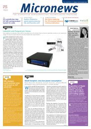
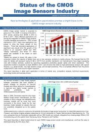
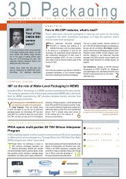
Shipments (in Munits)<br />
<strong>Flip</strong> <strong>Chip</strong> packages 2010-2016 unit forecasts<br />
25 000<br />
20 000<br />
<strong>Flip</strong>-<strong>Chip</strong> package unit shipments Forecast<br />
by end marke area (in Munits)<br />
Yole Developpement © April 2011<br />
15 000<br />
10 000<br />
5 000<br />
0<br />
2010 2011 2012 2013 2014 2015 2016<br />
automotive 8 11 13 17 24 30 35<br />
aerospace and defense 12 13 14 16 18 19 21<br />
industrial & medical 48 54 60 69 80 92 105<br />
consumer 4 301 4 380 4 434 4 460 4 446 4 636 4 816<br />
telecommunications 7 212 8 194 8 678 9 206 9 662 10 054 10 425<br />
computing 5 447 5 728 6 180 6 676 7 187 7 679 8 024<br />
• <strong>Flip</strong> <strong>Chip</strong> is primarily driven by computing, telecom / mobile and home consumer related applications<br />
• <strong>Flip</strong> <strong>Chip</strong> accounted for > 17 billion units as of 2010, i.e. 11% of all packaged Ics, with a CAGR limited to 5.5%<br />
– This low rate does not reflect the strong dynamism of flip-chip technology currently happending in the digital CMOS<br />
space. Indeed, we expect the 2010-2011 <strong>Flip</strong>-<strong>Chip</strong> in package of large digital CMOS ICs CAGR to be 20% !<br />
– However, overall CAGR is actually lowered by the massive move of RF filters from flip chip to full wafer level CSP (Fan-in<br />
WLP), as well as the slower growth of display LCD drivers<br />
© 2011 • 19<br />
Copyrights © Yole Développement SARL. All rights reserved.
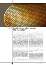
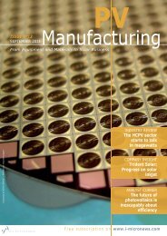
<strong>Flip</strong>-<strong>Chip</strong> Market Value<br />
Split by cost-of-ownership segments (Substrate, Assembly, Packaging and test)<br />
2010 Total <strong>Flip</strong>-<strong>Chip</strong> Market Value<br />
split by cost-of-ownership supply chain segments - Total = B$ 16<br />
(substrates for LCD drivers excluded, service margin included)<br />
Yole Développement, April 2011<br />
16%<br />
17%<br />
34%<br />
Substrate (rigid substrates, no flex for<br />
display)<br />
Wafer repassivation, redistribution and<br />
bumping<br />
14%<br />
19%<br />
Assembly (dicing, pick & place,<br />
underfilling, molding, marking, packing)<br />
Wafer probe test<br />
Final test<br />
• In 2010, the total <strong>Flip</strong> <strong>Chip</strong> Assembly, Packaging and Test Market totaled B$ 16<br />
© 2011 • 20<br />
Copyrights © Yole Développement SARL. All rights reserved.
About Yole’s Advanced Packaging Analysts<br />
Jean-Marc Yannou<br />
– Jean-Marc joined Yole<br />
Développement as technology and<br />
market expert in the fields of<br />
advanced packaging and<br />
Integrated Passive Devices. He<br />
has 15-years of experience in the<br />
semiconductor industry. He<br />
worked for Texas Instruments &<br />
NXP semiconductors where he<br />
was Innovation Manager for<br />
System-in-Package technologies<br />
Contact: yannou@yole.fr<br />
Jerome Baron<br />
– Jerome is leading the MEMS &<br />
Advanced Packaging market<br />
research at Yole Developpement.<br />
He has been following the 3D<br />
packaging market evolution since<br />
its early beginnings at device,<br />
equipment and material levels. He<br />
was granted a Master of Science<br />
degree in Nanotechnologies from<br />
the National Institute of Applied<br />
Sciences in Lyon, France<br />
Contact: baron@yole.fr<br />
Phil Garrou<br />
– Phil recently joined Yole<br />
Développement forces as senior<br />
technical advisor in the fields of<br />
advanced packaging. Phil as<br />
more than 20 years extensive<br />
experiences in the<br />
semiconductor industry where he<br />
mainly served as global<br />
marketing manager for DOW<br />
Chemical’s BCB polymer<br />
business<br />
Contact: garrou@yole.fr<br />
Christophe Zinck<br />
– Christophe joined Yole<br />
Developpement after several<br />
positions in the wafer fab and<br />
packaging environments of CEA-<br />
Leti, STMicroelectronics and then<br />
Triquint Semiconductor, where<br />
he was lead manager for flip-chip<br />
and wafer-level-packaging<br />
technologies implementation<br />
Contact: zinck@yole.fr<br />
© 2011 • 21<br />
Copyrights © Yole Développement SARL. All rights reserved.
© 2009<br />
Osram<br />
IR<br />
Copyrights © Yole Dévelo pement SARL. A l rights reserved.<br />
Yole activities in Advanced Packaging<br />
Media business<br />
News feed / Magazines / Webcasts<br />
Market Research<br />
Reports<br />
Market research,<br />
Technology & Strategy<br />
Consulting services<br />
www.yole.fr<br />
HB-LED Packaging<br />
Technology & Market Trends<br />
© 2011 • 22<br />
Copyrights © Yole Développement SARL. All rights reserved.
Osram<br />
IR<br />
Copyrights © Yole Développement SARL. All rights reserved.<br />
<strong>Chip</strong>works<br />
EVG<br />
SUSS<br />
DuPont<br />
Tessera<br />
NEC-Schott<br />
BC Tech<br />
STS<br />
Brewer Science<br />
Copyrights © Yole Développement SARL. All rights reserved.<br />
N<br />
o<br />
k<br />
i<br />
a<br />
F<br />
r<br />
e<br />
e<br />
s<br />
c<br />
a<br />
l<br />
e<br />
S<br />
i<br />
l<br />
e<br />
x<br />
D<br />
u<br />
P<br />
o<br />
n<br />
t<br />
Copyrights © Yole Développement SA. All rights reserved.<br />
I<br />
M<br />
E<br />
C<br />
N<br />
o<br />
k<br />
i<br />
a<br />
F<br />
r<br />
e<br />
e<br />
s<br />
c<br />
a<br />
l<br />
e<br />
S<br />
i<br />
l<br />
e<br />
x<br />
D<br />
u<br />
P<br />
o<br />
n<br />
t<br />
I<br />
M<br />
E<br />
C<br />
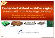
Our latest market reports…<br />
HB-LED Packaging<br />
Technology & Market Trends<br />
Equipment Advanced Packaging<br />
& Materials<br />
for<br />
Equipment<br />
Wafer-Level-Packaging<br />
& Materials<br />
Via First vs. Via Last?<br />
3D integration Scenarios<br />
3D IC & TSV<br />
2010 Market Analysis<br />
© 2009<br />
© 2010<br />
WL CSP<br />
2011 Report update<br />
3D Glass & Silicon<br />
interposers - 2010 Report<br />
IPD - Thin-film<br />
Integrated Passive Devices<br />
N<br />
o<br />
k<br />
i<br />
a<br />
TSV +<br />
Cost Analysis Tool for<br />
your 3D IC manufacturing<br />
CMOS Image Sensors<br />
Technologies & Markets Trends<br />
MEMS Packaging<br />
Market & Technology Trends<br />
<strong>Flip</strong>-chip<br />
2011 Report<br />
TSV Scenario Cost structure breakdown<br />
$27<br />
7% $23<br />
6%<br />
Via / Etching Drilling<br />
Via Isolation<br />
Via filling<br />
$168<br />
41%<br />
$109<br />
26%<br />
Temporary bonding<br />
Thinning<br />
Stress release<br />
$8<br />
$31<br />
$9 $37 2%<br />
7%<br />
2% 9%<br />
BEOL (Pads)<br />
Bonding<br />
© 2010<br />
6 & 6 mm<br />
6 & 6 mm<br />
© 2010<br />
1995<br />
~125 sq mm ~100 sq mm ~25 sq mm<br />
1996-2002<br />
1999 - today 2006<br />
1995<br />
~125 sq mm ~100 sq mm ~25 sq mm<br />
1996-2002<br />
1999 - today 2006<br />
Sidebraze DIP<br />
Plastic PDIP<br />
SMT SOIC<br />
& Die Down<br />
Stacked Die<br />
QFN<br />
Sidebraze DIP<br />
Plastic PDIP<br />
SMT SOIC<br />
& Die Down<br />
Stacked Die<br />
QFN<br />
© 2011 • 23<br />
Copyrights © Yole Développement SARL. All rights reserved.