T/3000 - HVTEST South Africa
T/3000 - HVTEST South Africa
T/3000 - HVTEST South Africa

You also want an ePaper? Increase the reach of your titles
YUMPU automatically turns print PDFs into web optimized ePapers that Google loves.
T/<strong>3000</strong><br />
T/<strong>3000</strong><br />
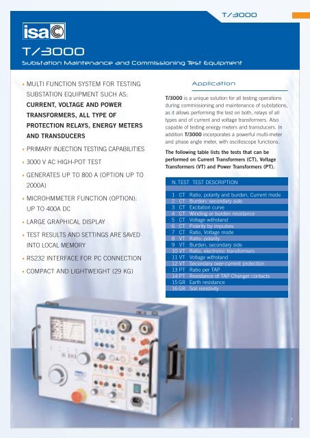
Substation Maintenance and Commissioning Test Equipment<br />
• MULTI FUNCTION SYSTEM FOR TESTING<br />
SUBSTATION EQUIPMENT SUCH AS:<br />
CURRENT, VOLTAGE AND POWER<br />
TRANSFORMERS, ALL TYPE OF<br />
PROTECTION RELAYS, ENERGY METERS<br />
AND TRANSDUCERS<br />
• PRIMARY INJECTION TESTING CAPABILITIES<br />
• <strong>3000</strong> V AC HIGH-POT TEST<br />
• GENERATES UP TO 800 A (OPTION UP TO<br />
2000A)<br />
• MICROHMMETER FUNCTION (OPTION):<br />
UP TO 400A DC<br />
• LARGE GRAPHICAL DISPLAY<br />
• TEST RESULTS AND SETTINGS ARE SAVED<br />
INTO LOCAL MEMORY<br />
• RS232 INTERFACE FOR PC CONNECTION<br />
• COMPACT AND LIGHTWEIGHT (29 KG)<br />
Application<br />
T/<strong>3000</strong> is a unique solution for all testing operations<br />
during commissioning and maintenance of substations,<br />
as it allows performing the test on both, relays of all<br />
types and of current and voltage transformers. Also<br />
capable of testing energy meters and transducers. In<br />
addition T/<strong>3000</strong> incorporates a powerful multi-meter<br />
and phase angle meter, with oscilloscope functions.<br />
The following table lists the tests that can be<br />
performed on Current Transformers (CT), Voltage<br />
Transformers (VT) and Power Transformers (PT).<br />
N. TEST TEST DESCRIPTION<br />
1 CT Ratio, polarity and burden, Current mode<br />
2 CT Burden; secondary side<br />
3 CT Excitation curve<br />
4 CT Winding or burden resistance<br />
5 CT Voltage withstand<br />
6 CT Polarity by impulses<br />
7 CT Ratio, Voltage mode<br />
8 VT Ratio; polarity<br />
9 VT Burden, secondary side<br />
10 VT Ratio, electronic transformers<br />
11 VT Voltage withstand<br />
12 VT Secondary over-current protection<br />
13 PT Ratio per TAP<br />
14 PT Resistance of TAP Changer contacts<br />
15 GR Earth resistance<br />
16 GR Soil resistivity<br />
1
T/<strong>3000</strong><br />
The table below lists the relays that can be set and tested by T/<strong>3000</strong>.<br />
RELAY TYPE<br />
IEEE No<br />
RELAY TYPE<br />
IEEE No<br />
Distance (3 sets)<br />
Synchronizing<br />
Over/under-voltage<br />
Power, varmetric or wattmetric<br />
Under current<br />
Reverse phase current<br />
Instantaneous overcurrent<br />
Ground fault<br />
Timed overcurrent<br />
Power factor<br />
Directional overcurrent<br />
Directional ground fault<br />
Automatic reclose<br />
21<br />
25<br />
27 - 59<br />
32 - 92<br />
37<br />
46<br />
50<br />
50N<br />
51<br />
55<br />
67<br />
67N<br />
79<br />
Frequency<br />
Frequency rate of change<br />
Motor protection<br />
Differential (starter only)<br />
Directional voltage<br />
Tripping relay<br />
OTHER DEVICES<br />
Voltage regulation<br />
Timers<br />
Transducers<br />
Energy meters<br />
81<br />
81<br />
86<br />
87<br />
91<br />
94<br />
Typical application<br />
Test of Current Transformer<br />
• CT RATIO V AND POLARITY - VOLTAGE METHOD<br />
USED OUTPUT: 90V, 250V or <strong>3000</strong> V AC.<br />
USED INPUT: LOW AC VOLTAGE - 10 V AC.<br />
CT EXCITATION<br />
USED OUTPUT: 90V, 250V or <strong>3000</strong> V AC.<br />
USED INPUT: Internal measurement.<br />
2
T/<strong>3000</strong><br />
• CT BURDEN SECONDARY SIDE:<br />
USED OUTPUT: 10 A or 40 A AC.<br />
USED INPUT: LOW AC VOLTAGE - 10 V AC<br />
• WINDING RESISTANCE:<br />
USED OUTPUT: 6 A DC<br />
USED INPUT: 10 V DC<br />
• VOLTAGE WITHSTAND:<br />
USED OUTPUT: <strong>3000</strong> V AC<br />
USED INPUT: Internal measurement.<br />
• CT RATIO AND POLARITY – CURRENT METHOD<br />
USED OUTPUT: 800 A AC<br />
USED INPUT: LOW AC CURRENT - 10 A AC.<br />
3
T/<strong>3000</strong><br />
Typical application<br />
Test of Voltage Transformer<br />
• VT RATIO AND POLARITY<br />
USED OUTPUT: <strong>3000</strong> V AC.<br />
USED INPUT: LOW or HIGH AC VOLTAGE - 10 V AC OR 600 V AC.<br />
• VT BURDEN<br />
USED OUTPUT: 10 A AC.<br />
USED INPUT: LOW or HIGH AC VOLTAGE - 10 V AC<br />
OR 600 V AC.<br />
• VOLTAGE WITHSTAND<br />
USED OUTPUT: <strong>3000</strong> V AC<br />
USED INPUT: Internal measurement.<br />
• RATIO OF ELECTRONIC VOLTAGE TRANSFORMER<br />
USED OUTPUT: <strong>3000</strong> V AC.<br />
USED INPUT: LOW or HIGH AC VOLTAGE - 10 V AC OR 600 V AC.<br />
4
T/<strong>3000</strong><br />
Typical application<br />
Power Transformer<br />
• RATIO PER TAP<br />
USED OUTPUT: <strong>3000</strong> V AC.<br />
USED INPUT: LOW or HIGH AC VOLTAGE - 10 V AC OR 600 V AC.<br />
• TAP CHANGER RESISTANCE AND CONTINUITY<br />
USED OUTPUT: 6 A DC<br />
USED INPUT: 10 V DC<br />
Typical application<br />
Relay Testing<br />
• PRIMARY INJECTION<br />
USED OUTPUT: 800 A<br />
USED INPUT: TIMER<br />
• SECONDARY INJECTION<br />
USED OUTPUT: 800A, 40A or 10 A<br />
USED INPUT: TIMER<br />
5
T/<strong>3000</strong><br />
• SCOPE FUNCTION<br />
USED OUTPUT: ANY<br />
USED INPUT: V and I<br />
System description<br />
T/<strong>3000</strong> contains three independent generators:<br />
• Main generator. It has six outputs: High AC current;<br />
Low AC current; Low DC current; Current impulses;<br />
High AC voltage; Low AC voltage 1.<br />
• Auxiliary AC voltage generator 2: it generates an<br />
independent, phase adjustable AC voltage.<br />
• Auxiliary DC voltage generator, to feed relays under test.<br />
All outputs are adjustable and metered on the large,<br />
graphic LCD display. With the multi-purpose control<br />
knob and the graphic LCD display it is possible to enter<br />
the MENU mode, that allows to control all functions,<br />
and makes T/<strong>3000</strong> the most powerful testing device,<br />
with manual and automatic testing capabilities, and<br />
with the possibility to transfer test results to a PC via the<br />
RS232 interface. These results can be recorded,<br />
displayed and analysed by the powerful X.PRO-<strong>3000</strong><br />
software, which operates with all WINDOWS versions,<br />
starting from WINDOWS 98 included.<br />
Additional features are:<br />
. Oscilloscope function: it is possible to display the<br />
current and voltage waveform measured;<br />
. Two independent measurement inputs, for current<br />
and voltage, and with High and Low inputs each,<br />
allow measuring CT or VT outputs or any other source;<br />
. The optional thermal printer gives the immediate<br />
printout of the CT saturation curve and other test results;<br />
. An auxiliary output contact, that follows START and<br />
STOP inputs, allows simulating the circuit breaker.<br />
The instrument is housed in a transportable aluminium<br />
box, which is provided with removable cover and<br />
handles for ease of transportation.<br />
NOTE: WINDOWS is a trademark of MICROSOFT inc.<br />
T/<strong>3000</strong> Specification<br />
Main Generator<br />
The main generator has six outputs: High AC current; Low<br />
AC current; Low DC current; Current impulses; High AC<br />
voltage; Low AC voltage. Output adjustment is performed<br />
via a knob. The following specification applies to the<br />
separate usage of these outputs.<br />
High AC current output<br />
APPLICATION:<br />
. CT TESTING: RATIO, POLARITY, BURDEN<br />
. RELAY TESTING<br />
. PRIMARY INJECTION<br />
HIGH POWER RANGE<br />
CURRENT OUTPUT LOAD RECOVERY<br />
OUTPUT POWER TIME TIME<br />
A VA s min<br />
100 600 STEADY -<br />
150 800 15 min 30<br />
200 1000 4 min 15<br />
400 1600 15 5<br />
600 2000 5 3<br />
800 2000 1 2<br />
LOW POWER RANGE<br />
CURRENT OUTPUT LOAD RECOVERY<br />
OUTPUT POWER TIME TIME<br />
A VA s min<br />
30 60 STEADY -<br />
50 80 10 min 10<br />
Low AC current output<br />
APPLICATION:<br />
. CT TESTING: BURDEN, SECONDARY SIDE<br />
. VT TESTING: OVERCURRENT PROTECTION<br />
HIGH POWER RANGE<br />
RANGE CURRENT OUTPUT LOAD RECOVERY<br />
A OUTPUT POWER TIME TIME<br />
AC A VA s min<br />
40 12 300 STEADY -<br />
18 15 min 30<br />
24 4 min 15<br />
36 800 15 5<br />
48 5 3<br />
60 1000 1 2<br />
10 5 400 STEADY -<br />
7.5 15 min 30<br />
10 800 60 15<br />
15 30 10<br />
20 1000 15 5<br />
6
T/<strong>3000</strong><br />
LOW POWER RANGE<br />
RANGE CURRENT OUTPUT LOAD RECOVERY<br />
A OUTPUT POWER TIME TIME<br />
AC A VA s min<br />
40 12 60 STEADY -<br />
18 10 min 30<br />
24 60 10<br />
36 1 2<br />
10 5 60 STEADY -<br />
6 10 min 45<br />
7 60 2<br />
10 1 2<br />
Low DC current output<br />
APPLICATION:<br />
. CT TESTING: WINDING RESISTANCE, BURDEN<br />
RESISTANCE<br />
. PT TESTING: TAP-CHANGER CONTACT RESISTANCE<br />
CURRENT LOAD OUTPUT LOAD RECOVERY<br />
OUTPUT RESISTANCE POWER TIME TIME<br />
A Ohm W min min<br />
6 0 0 STEADY -<br />
3 2 18 STEADY -<br />
1 8 8 STEADY -<br />
Current impulses output<br />
APPLICATION:<br />
. CT TESTING: POLARITY TEST WITH IMPULSE METHOD<br />
- Current range: from 0 to 10 A peak.<br />
High AC voltage output<br />
Two version are available: <strong>3000</strong>V or 1200V output<br />
APPLICATION:<br />
. CT TESTING: EXCITATION CURVE, VOLTAGE<br />
WITHSTAND<br />
. VT TESTING: RATIO, POLARITY, ELECTRONIC<br />
VOLTAGE TRANSFORMER<br />
. PT TESTING: RATIO PER TAP<br />
HIGH POWER RANGE<br />
<strong>3000</strong> V version<br />
VOLTAGE CURRENT OUTPUT LOAD RECOVERY<br />
OUTPUT OUTPUT POWER TIME TIME<br />
V A VA min min<br />
<strong>3000</strong> 0.2 600 STEADY -<br />
0.6 1800 1 8<br />
In alternative<br />
1200V version<br />
VOLTAGE CURRENT OUTPUT LOAD RECOVERY<br />
OUTPUT OUTPUT POWER TIME TIME<br />
V A VA min min<br />
1200 0.5 600 STEADY -<br />
1200 1.5 1800 1 8<br />
LOW POWER RANGE<br />
VOLTAGE CURRENT OUTPUT LOAD RECOVERY<br />
OUTPUT OUTPUT POWER TIME TIME<br />
V A VA min min<br />
600 0.1 60 STEADY -<br />
500 0.2 120 1 8<br />
Low AC voltage output<br />
APPLICATION:<br />
. CT TESTING: RATIO WITH VOLTAGE METHOD<br />
. VT TESTING: BURDEN SECONDARY SIDE<br />
VOLTAGE VOLTAGE OUTPUT LOAD RECOVERY<br />
V OUTPUT POWER TIME TIME<br />
a.c. V VA min min<br />
250 250 125 STEADY -<br />
200 200 3 9<br />
Auxiliary AC voltage<br />
APPLICATION:<br />
. RELAY TESTING<br />
RANGE V<br />
MAX CURRENT mA<br />
65 500<br />
130 250<br />
260 125<br />
Auxiliary AC voltage<br />
APPLICATION: . RELAY TESTING<br />
Phase angle sfifter<br />
• Phase angle adjustment: via the multi-function knob.<br />
• Phase angle range: from 0° to 360°.<br />
• Adjustment resolution: 1° (one degree).<br />
Frequency & frequency rate<br />
of change generator<br />
• Frequency range: 40 Hz to 500 Hz.<br />
• Frequency adjustment: 1 mHz, via control knob.<br />
• Frequency ROC range: from 0.01 Hz/s to 99.99 Hz/s.<br />
7
T/<strong>3000</strong><br />
Auxiliary DC voltage<br />
Measuring Section<br />
• D.C. voltage ranges: 130 V or 240 V.<br />
• D.C. voltage power: 90 W at full range, continuous duty,<br />
with a current limit of 0.9 A @ 130 V and 0.45 A @ 240 V.<br />
Timer<br />
Available measurements:<br />
• Timer start: at test start, or by an external contact;<br />
• Metering of elapsed time between START and STOP;<br />
• Current generation elapsed time.<br />
• Time can be metered as seconds or cycles.<br />
. Inputs: free of voltage or with voltage.<br />
. Programmable voltage threshold: 12 V or 80 V.<br />
. Metering range, in seconds: from 0 to 99999.9 s.<br />
. Resolution: 1 ms (up to 9.999 s).<br />
. Metering range, in cycles: from 0 to 5999999 (60Hz).<br />
. Resolution: 0.1 cycles (up to 999 cycles).<br />
Counting mode: this mode is foreseen for the test of<br />
energy meters. Maximum input frequency: 10 kHz.<br />
Auxiliary binary Output<br />
Contact range: 5 A; 250 V AC; 120 V DC<br />
Output measurements<br />
Current and voltage AC and DC outputs measurement<br />
accuracy: ± 0.5%.<br />
Phase angle measurement accuracy: 1°.<br />
Frequency accuracy: 1 mHz.<br />
Other measurements available on T/<strong>3000</strong>:<br />
The following measurement are calculated from the<br />
T/<strong>3000</strong> generated outputs:<br />
OUTPUT MEASUREMENTS:<br />
ACTIVE POWER<br />
P<br />
REACTIVE POWER<br />
Q<br />
APPARENT POWER<br />
S<br />
POWER FACTOR<br />
p.f.<br />
IMPEDANCE<br />
Z and ϕ<br />
ACTIVE IMPED. COMPONENT R<br />
REACTIVE IMPEDANCE COMP. X<br />
RATIO<br />
CT or VT or PT<br />
POLARITY<br />
CT or VT or PT<br />
BURDEN<br />
CT<br />
VOLTAGE AND CURRENT KNEE<br />
External Inputs<br />
Measurement<br />
Current measurements<br />
. Two inputs: 20 mA AC or DC or 10 A AC.<br />
. Accuracy: 0.5%<br />
Possibility to display the current waveform.<br />
Voltage measurement<br />
. Two inputs: 10 V or 600 V, AC or DC<br />
. Accuracy: 0.5%<br />
Possibility to display the voltage waveform.<br />
Other measurements available on the T/<strong>3000</strong><br />
calculated from external inputs.<br />
EXTERNAL INPUTS MEASUREMENTS:<br />
ACTIVE POWER<br />
REACTIVE POWER<br />
APPARENT POWER<br />
POWER FACTOR<br />
IMPEDANCE<br />
ACTIVE IMPEDANCE COMP.<br />
REACTIVE IMPEDANCE COMP.<br />
FREQUENCY<br />
PHASE ANGLE<br />
PHASE ANGLE<br />
RESISTANCE<br />
P<br />
Q<br />
S<br />
p.f.<br />
Z and ϕ<br />
R<br />
X<br />
f<br />
IEXT to V AUX<br />
VEXT to V AUX<br />
R<br />
8
T/<strong>3000</strong><br />
Scope Function<br />
T/<strong>3000</strong> has an additional oscilloscope function that<br />
allows to display current and voltage waveforms.<br />
Graphical display<br />
The large graphical display has the following<br />
characteristics:<br />
• Pixels: 240x128;<br />
• backlight colour: white;<br />
• LCD type: FSTN;<br />
• View area: 135x80 mm.<br />
Local Memory<br />
Test results can be stored in the T/<strong>3000</strong> local memory<br />
(up to 500 results may be stored).<br />
At the end of test, settings and test results can be<br />
transmitted to a PC provided with X.PRO-<strong>3000</strong>.<br />
The software allows saving test results and examining<br />
them. X.PRO-<strong>3000</strong> is also a powerful report editor that<br />
allows to prepare professional test reports.<br />
Test settings can be stored and recalled from the<br />
memory. Up to 10 settings can be stored and recalled.<br />
Software X.PRO-<strong>3000</strong><br />
Other characteristics<br />
- Interface: serial RS232; baud rate 57600 baud<br />
- Mains supply: 230 V ± 10%; 50-60 Hz, OR 115 V ±<br />
10%; 50-60 Hz; to be specified at order. (There are<br />
power reduction for mains voltage below 220V).<br />
- Dimensions: 450 (W) x 320 (D) x 240 (H) mm.<br />
- Weight: 29 kg.<br />
ACCESSORIES<br />
THE FOLLOWING ACCESSORIES ARE SUPPLIED<br />
WITH T/<strong>3000</strong><br />
X.PRO-<strong>3000</strong> Software<br />
When the PC is connected, settings can be created<br />
and transferred into T/<strong>3000</strong> using X.PRO-<strong>3000</strong>.<br />
X.PRO-<strong>3000</strong> is a user friendly software that allows via a<br />
graphical interface, to control the set-up of T/<strong>3000</strong> and<br />
to download test results. X.PRO-<strong>3000</strong> is also a<br />
powerful report editor that allows to create professional<br />
Test Reports that can be exported in Access format.<br />
Connection cable and test connectors<br />
- N. 1 Mains supply cable, 2 m long.<br />
- N. 1 Grounding cable, 4 m long, terminated on one<br />
side with a 4 mm banana plug, and on the other side<br />
with an earth connection clamp.<br />
- N. 1 Interface cable for RS232 port.<br />
- N. 2 High voltage connection cables, 4 m long, 5 kV,<br />
with earth screen. Terminated on both sides with HV<br />
connectors.<br />
- N. 2 Clamps for the HV connection.<br />
- N. 2 High current connection cables, 100 sq. mm, 4<br />
m long. Terminated on one side with the high current<br />
connector, and on the other side with the high<br />
current clamp.<br />
- N. 2 Low current connection cables, 10 sq. mm, 4 m<br />
long. Terminated on both sides with a 4 mm banana plug.<br />
- N. 4 Clamps to connect low voltage or low current or<br />
measurements.<br />
- N. 1 Cable for low voltage or low current connection,<br />
shielded, 4 m long. Terminated on one side with the<br />
measurement connector, and on the other side with<br />
two 4 mm banana plugs.<br />
- Voltage outputs (4 cables: 2 red and 2 black);<br />
9
T/<strong>3000</strong><br />
- Measurement inputs (4 cables: 2 red and 2 black);<br />
- Auxiliary output (2 cables: 1 red and 1 blue);<br />
- Trip inputs (4 cables; blue).<br />
- The instrument comes complete with the following items:<br />
. User’s manual;<br />
. Spare fuses (no. 5), T16A;<br />
. Software X.PRO-<strong>3000</strong> with user manual.<br />
Optional accessories<br />
Thermal printer<br />
The optional thermal printer, for the printout of the V-I<br />
curve in the CT saturation test and other test results.<br />
Thermal Paper 48 mm wide.<br />
Transit case<br />
Heavy duty aluminium transit case with wheels allows<br />
delivering T/<strong>3000</strong> with no concern about transport shocks.<br />
Current clamp<br />
The current clamp allows to avoid the opening the<br />
secondary current circuit when performing the primary<br />
test of CT burden.<br />
Earth resistance and soil resistività kit.<br />
Complete kit including cables, drums and spikes.<br />
Optional Modules<br />
High IDC Module - 400A<br />
The high DC current module allows the measurement<br />
of the low contact resistance of high voltage breakers<br />
or of joints. The option is connected to the high AC<br />
current output of T/<strong>3000</strong>; the current measurement is<br />
connected to the low DC current measurement input;<br />
the drop voltage is connected to the low voltage<br />
measurement input. DC current output is: 100 A<br />
steady; 200 A for 4 minutes; 400 A for 15 s.<br />
The selection of this function is performed via menu; the<br />
screen displays: test current; joint voltage; contact<br />
resistance. Resistance measurement ranges: µOhm 100.0,<br />
1.000, 10.00, 100.0 mOhm; 1.000 Ohm, auto-ranging.<br />
The connection cables are included with the option.<br />
Current booster - 2000A AC<br />
The current booster module allows performing high<br />
current primary tests. The option is connected to the<br />
high AC current output of T/<strong>3000</strong>, and boosts the<br />
output current on two ranges: 1000 A or 2000 A.<br />
Output characteristics are the following.<br />
RANGE OUTPUT POWER TEST<br />
A A VA DURATION<br />
1000 500 800 4 min<br />
1000 1400 15 s<br />
2000 1000 800 4 min<br />
2000 1200 15 s<br />
Current output is measured by connecting the option<br />
to the external high current measurement.<br />
The selection of this function is performed via menu;<br />
the screen displays the output current as kA.<br />
The connection cables are included with the option.<br />
Safety Features and<br />
Protections<br />
- Fuse on the mains supply.<br />
- At power-on, a diagnostic sequence controls:<br />
. Key microprocessor board components;<br />
. Auxiliary supply voltages.<br />
If something is wrong, the operator is alerted by a<br />
message.<br />
- Emergency pushbutton: if pressed, all main outputs<br />
are removed.<br />
- The high voltage output has the following protections:<br />
. Confirmation key: if not turned, the HV output is not<br />
generated;<br />
. The HV is generated only if selected.<br />
- Thermal NTC sensor on the main and auxiliary<br />
transformers. In case of over-temperature, an alarm<br />
message is displayed.<br />
- Thermal sensors or the SCR that controls current<br />
injection, and of the internal temperature. In case of<br />
over-temperature, an alarm message is displayed.<br />
- If maximum current limits and time duration of power<br />
transformer generators are reached, the generation is<br />
interrupted, and the operator is warned by an alarm<br />
message.<br />
- The DC current source is protected against overvoltages.<br />
In addition, the output is automatically kept<br />
to zero as test stops, so that any residual energy on<br />
the external load is discharged.<br />
- The auxiliary AC voltage is protected by an electronic<br />
circuit that stops the voltage generation and opens<br />
the connection to outputs socket in case of overload<br />
(short circuit included). In case of intervention, an<br />
10
T/<strong>3000</strong><br />
alarm message is displayed. Via the control knob the<br />
operator can reset the alarm and close the relay to<br />
restore operation. The auxiliary AC voltage is also<br />
protected by a thermo switch that intervenes in case<br />
of over-heating. In case of intervention, an alarm<br />
message is displayed.<br />
- The DC voltage generator is protected by a current<br />
limiter. The user notices the low voltage and removes the<br />
overload. The fuse protects the case of counter-feed.<br />
- Re-triggering fuse on the auxiliary contact.<br />
- Timer inputs are protected against wrong selections.<br />
If the voltage free input is selected and a voltage is<br />
applied less than 250 V ac or 275 V DC, circuits will<br />
not be damaged.<br />
- Trip inputs and the auxiliary relay contacts are<br />
protected by devices rated 380 V AC, which limit the<br />
maximum voltage between sockets and among<br />
sockets and ground.<br />
- The 20 mA measurement input is protected by a fuse.<br />
Applicable Standards<br />
The test set conforms to the EEC directives regarding<br />
Electromagnetic Compatibility and Low Voltage<br />
instruments.<br />
A) Electromagnetic Compatibility:<br />
Directive no. 89/336/CEE dated may 3, 1989, modified<br />
by the directive 92/31/CEE dated may 5, 1992.<br />
B) Low Voltage Directive:<br />
Directive n. 73/23/CEE, modified by the directive<br />
93/68/CEE.<br />
Applicable standards, for a class I instrument,<br />
pollution degree 2, Installation category II:<br />
. CEI EN 61010-1. In particular:<br />
. Inputs/outputs protection: IP 2X - CEI 70-1.<br />
. Operating temperature: 0 to 50 °C; storage: -40 °C to<br />
70 °C.<br />
. Relative humidity: 10 - 80% without condensing.<br />
The document is subject to change without notice<br />
11
H.V. TEST (PTY) LTD<br />
3 Gaiety Ave, Robindale, Randburg, <strong>South</strong> <strong>Africa</strong>, 2010 Tel: +27(11) 782 1010 Fax: +27(11) 782 2770<br />
P.O. Box 651287, Benmore, 2010 Email: sales@hvtest.co.za Website: www.hvtest.co.za